EP4317404A1 - Inspection system and inspection method - Google Patents
Inspection system and inspection method Download PDFInfo
- Publication number
- EP4317404A1 EP4317404A1 EP22775481.9A EP22775481A EP4317404A1 EP 4317404 A1 EP4317404 A1 EP 4317404A1 EP 22775481 A EP22775481 A EP 22775481A EP 4317404 A1 EP4317404 A1 EP 4317404A1
- Authority
- EP
- European Patent Office
- Prior art keywords
- mold
- microorganism
- inspection system
- inspection
- image data
- Prior art date
- Legal status (The legal status is an assumption and is not a legal conclusion. Google has not performed a legal analysis and makes no representation as to the accuracy of the status listed.)
- Pending
Links
Images






Classifications
-
- C—CHEMISTRY; METALLURGY
- C12—BIOCHEMISTRY; BEER; SPIRITS; WINE; VINEGAR; MICROBIOLOGY; ENZYMOLOGY; MUTATION OR GENETIC ENGINEERING
- C12Q—MEASURING OR TESTING PROCESSES INVOLVING ENZYMES, NUCLEIC ACIDS OR MICROORGANISMS; COMPOSITIONS OR TEST PAPERS THEREFOR; PROCESSES OF PREPARING SUCH COMPOSITIONS; CONDITION-RESPONSIVE CONTROL IN MICROBIOLOGICAL OR ENZYMOLOGICAL PROCESSES
- C12Q1/00—Measuring or testing processes involving enzymes, nucleic acids or microorganisms; Compositions therefor; Processes of preparing such compositions
- C12Q1/02—Measuring or testing processes involving enzymes, nucleic acids or microorganisms; Compositions therefor; Processes of preparing such compositions involving viable microorganisms
- C12Q1/04—Determining presence or kind of microorganism; Use of selective media for testing antibiotics or bacteriocides; Compositions containing a chemical indicator therefor
-
- G—PHYSICS
- G06—COMPUTING OR CALCULATING; COUNTING
- G06V—IMAGE OR VIDEO RECOGNITION OR UNDERSTANDING
- G06V20/00—Scenes; Scene-specific elements
- G06V20/60—Type of objects
- G06V20/69—Microscopic objects, e.g. biological cells or cellular parts
- G06V20/693—Acquisition
-
- C—CHEMISTRY; METALLURGY
- C12—BIOCHEMISTRY; BEER; SPIRITS; WINE; VINEGAR; MICROBIOLOGY; ENZYMOLOGY; MUTATION OR GENETIC ENGINEERING
- C12M—APPARATUS FOR ENZYMOLOGY OR MICROBIOLOGY; APPARATUS FOR CULTURING MICROORGANISMS FOR PRODUCING BIOMASS, FOR GROWING CELLS OR FOR OBTAINING FERMENTATION OR METABOLIC PRODUCTS, i.e. BIOREACTORS OR FERMENTERS
- C12M41/00—Means for regulation, monitoring, measurement or control, e.g. flow regulation
- C12M41/30—Means for regulation, monitoring, measurement or control, e.g. flow regulation of concentration
- C12M41/36—Means for regulation, monitoring, measurement or control, e.g. flow regulation of concentration of biomass, e.g. colony counters or by turbidity measurements
-
- G—PHYSICS
- G01—MEASURING; TESTING
- G01N—INVESTIGATING OR ANALYSING MATERIALS BY DETERMINING THEIR CHEMICAL OR PHYSICAL PROPERTIES
- G01N1/00—Sampling; Preparing specimens for investigation
- G01N1/28—Preparing specimens for investigation including physical details of (bio-)chemical methods covered elsewhere, e.g. G01N33/50, C12Q
- G01N1/38—Diluting, dispersing or mixing samples
-
- G—PHYSICS
- G01—MEASURING; TESTING
- G01N—INVESTIGATING OR ANALYSING MATERIALS BY DETERMINING THEIR CHEMICAL OR PHYSICAL PROPERTIES
- G01N15/00—Investigating characteristics of particles; Investigating permeability, pore-volume or surface-area of porous materials
- G01N15/06—Investigating concentration of particle suspensions
- G01N15/0606—Investigating concentration of particle suspensions by collecting particles on a support
-
- G—PHYSICS
- G01—MEASURING; TESTING
- G01N—INVESTIGATING OR ANALYSING MATERIALS BY DETERMINING THEIR CHEMICAL OR PHYSICAL PROPERTIES
- G01N15/00—Investigating characteristics of particles; Investigating permeability, pore-volume or surface-area of porous materials
- G01N15/06—Investigating concentration of particle suspensions
- G01N15/075—Investigating concentration of particle suspensions by optical means
-
- G—PHYSICS
- G01—MEASURING; TESTING
- G01N—INVESTIGATING OR ANALYSING MATERIALS BY DETERMINING THEIR CHEMICAL OR PHYSICAL PROPERTIES
- G01N15/00—Investigating characteristics of particles; Investigating permeability, pore-volume or surface-area of porous materials
- G01N15/10—Investigating individual particles
- G01N15/14—Optical investigation techniques, e.g. flow cytometry
- G01N15/1429—Signal processing
- G01N15/1433—Signal processing using image recognition
-
- G—PHYSICS
- G01—MEASURING; TESTING
- G01N—INVESTIGATING OR ANALYSING MATERIALS BY DETERMINING THEIR CHEMICAL OR PHYSICAL PROPERTIES
- G01N15/00—Investigating characteristics of particles; Investigating permeability, pore-volume or surface-area of porous materials
- G01N15/10—Investigating individual particles
- G01N15/14—Optical investigation techniques, e.g. flow cytometry
- G01N15/1468—Optical investigation techniques, e.g. flow cytometry with spatial resolution of the texture or inner structure of the particle
-
- G—PHYSICS
- G06—COMPUTING OR CALCULATING; COUNTING
- G06T—IMAGE DATA PROCESSING OR GENERATION, IN GENERAL
- G06T7/00—Image analysis
- G06T7/0002—Inspection of images, e.g. flaw detection
- G06T7/0012—Biomedical image inspection
-
- G—PHYSICS
- G06—COMPUTING OR CALCULATING; COUNTING
- G06V—IMAGE OR VIDEO RECOGNITION OR UNDERSTANDING
- G06V10/00—Arrangements for image or video recognition or understanding
- G06V10/70—Arrangements for image or video recognition or understanding using pattern recognition or machine learning
-
- G—PHYSICS
- G06—COMPUTING OR CALCULATING; COUNTING
- G06V—IMAGE OR VIDEO RECOGNITION OR UNDERSTANDING
- G06V20/00—Scenes; Scene-specific elements
- G06V20/60—Type of objects
- G06V20/69—Microscopic objects, e.g. biological cells or cellular parts
- G06V20/698—Matching; Classification
-
- G—PHYSICS
- G01—MEASURING; TESTING
- G01N—INVESTIGATING OR ANALYSING MATERIALS BY DETERMINING THEIR CHEMICAL OR PHYSICAL PROPERTIES
- G01N15/00—Investigating characteristics of particles; Investigating permeability, pore-volume or surface-area of porous materials
- G01N15/10—Investigating individual particles
- G01N15/14—Optical investigation techniques, e.g. flow cytometry
- G01N2015/1486—Counting the particles
-
- G—PHYSICS
- G06—COMPUTING OR CALCULATING; COUNTING
- G06T—IMAGE DATA PROCESSING OR GENERATION, IN GENERAL
- G06T2207/00—Indexing scheme for image analysis or image enhancement
- G06T2207/30—Subject of image; Context of image processing
- G06T2207/30004—Biomedical image processing
- G06T2207/30024—Cell structures in vitro; Tissue sections in vitro
Definitions
- the present disclosure relates to an inspection system and inspection method.
- a service has been provided to inspect the presence or absence of and the type of environmental microorganisms (for example, mold) included in dust, etc., in air conditioners, and to provide the inspection results.
- the service provider can make proposals (for example, cleaning air conditioners and changing filters of air conditioners, etc.) to realize an optimal air environment according to the inspection results.
- the present disclosure provides an inspection system and inspection method that reduce the time required to inspect environmental microorganisms.
- the first aspect of the present disclosure is an inspection system for inspecting a microorganism or mold that is generated in an indoor environment or a device, the inspection system including
- an inspection system that reduces the time required to inspect environmental microorganisms can be provided.
- the second aspect of the present disclosure is an inspection system for inspecting a microorganism or mold that is generated in an indoor environment or a device, the inspection system including
- an inspection system that reduces the time required to inspect environmental microorganisms can be provided.
- the third aspect of the present disclosure is the inspection system according to the first or second aspect, wherein
- the fourth aspect of the present disclosure is the inspection system according to the third aspect, wherein the solution can be obtained by dissolving, in the solution, the sample collected from the indoor environment or the device.
- the fifth aspect of the present disclosure is the inspection system according to the third aspect, wherein the imaging target is collected from any of an air conditioner, an air cleaner, a humidifier, a ventilation system, a blower, or a surface of the indoor environment.
- the sixth aspect of the present disclosure is the inspection system according to the third aspect, further including a first model that has completed learning configured to determine an attribute of each region in the image data.
- the seventh aspect of the present disclosure is the inspection system according to the sixth aspect, further including a second model that has completed learning configured to determine a type of the microorganism or the mold, with respect to the region determined to include the microorganism or the mold by the first model that has completed learning.
- the eighth aspect of the present disclosure is the inspection system according to any one of the first to seventh aspects, wherein the output unit aggregates a number of the microorganism or the mold for each type of the microorganism or the mold in the image data captured by the imaging unit, and outputs the aggregated number.
- the ninth aspect of the present disclosure is an inspection system for inspecting a microorganism or mold that is generated in an indoor environment or a device, the inspection system including
- the tenth aspect of the present disclosure is an inspection system for inspecting a microorganism or mold that is generated in an indoor environment or a device, the inspection system including
- the eleventh aspect of the present disclosure is the inspection system according to any one of the third to seventh aspects, wherein the imaging target is obtained by dispersing and dissolving the collected sample in the solution.
- the twelfth aspect of the present disclosure is the inspection system according to the eleventh aspect, wherein the imaging target is obtained by dispersing and dissolving, in the solution, the sample collected from an air conditioner.
- the thirteenth aspect of the present disclosure is the inspection system according to the eleventh or twelfth aspect, wherein the imaging target is obtained by dispersing and dissolving the collected sample in a saline solution in which a surfactant is dissolved.
- the fourteenth aspect of the present disclosure is the inspection system according to any one of the eleventh to thirteenth aspects, wherein the imaging target includes a first solution obtained by dispersing and dissolving the collected sample in a saline solution in which a surfactant is dissolved, and a second solution obtained by further diluting the first solution by using a saline solution in which a surfactant is dissolved.
- each of the regions, for which the attribute is determined by the first model that has completed learning is 32 pixels ⁇ 32 pixels or more.
- the sixteenth aspect of the present disclosure is the inspection system according to the seventh aspect, wherein the first model that has completed learning is generated by performing learning processing by using learning data, wherein in the learning data,
- the seventeenth aspect of the present disclosure is the inspection system according to the seventh aspect, wherein when the type of the microorganism or the mold is determined, the second model that has completed learning counts a number of the microorganism or the mold for each determined type.
- the eighteenth aspect of the present disclosure is the inspection system according to any one of the first to seventeenth aspects, wherein the inspection system is a mobile terminal, and the imaging unit is built in the mobile terminal.
- the nineteenth aspect of the present disclosure is the inspection system according to the seventh aspect, further including
- the twentieth aspect of the present disclosure is the inspection system according to any one of the seventh, fifteenth, and sixteenth aspects , wherein the first model that has completed learning is a YOLO that has completed learning.
- the twenty-first aspect of the present disclosure is the inspection system according to the seventh or seventeenth aspect, wherein
- the twenty-second aspect of the present disclosure is the inspection system according to any one of the seventh, seventeenth, and twenty-first aspects, wherein the second model that has completed learning is a DML that has completed learning.
- the twenty-third aspect of the present disclosure is an inspection method performed by an inspection system for inspecting a microorganism or mold that is generated in an indoor environment or a device, the inspection method including an imaging step of directly capturing a sample collected from the indoor environment or the device; and an output step of inspecting the microorganism or the mold in captured image data, and outputting an inspection result.
- the twenty-fourth aspect of the present disclosure is an inspection method performed by an inspection system for inspecting a microorganism or mold that is generated in an indoor environment or a device, the inspection method including
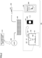
- FIG. 1 is a first diagram illustrating an application example of the inspection service providing system in the learning phase.
- an inspection service providing system 100 includes a mobile terminal 120 (an example of the inspection system according to the first embodiment), an imaging table 130, and an image processing apparatus 140.
- the imaging target captured by using the mobile terminal 120 is acquired by the following procedures and is directly captured under visible light (for example, under fluorescent light) or ultraviolet light.
- image capturing means obtaining information about the appearance (color and shape) of an individual unit of environmental microorganism (in the case of mold, an individual unit of mold, specifically, one unit of spores and hyphae; in the case of bacteria, an individual unit of bacteria).
- the imaging table 130 is configured to be portable and includes a lens 131, a mounting part 132, and a lens support part 133 as illustrated in FIG. 1 .
- the lens 131 enlarges the imaging target (in the example in FIG. 1 , the preparation 180_1) to a predetermined magnification.
- the mounting part 132 is a member on which an imaging target (in the example in FIG. 1 , the preparation 180_1) is mounted.
- the lens support part 133 is a member for supporting the lens 131 at a position separated by a predetermined distance from the imaging target mounted on the mounting part 132, and is a member on which the mobile terminal 120 is mounted on the upper surface.
- the lens support part 133 may be provided with a lifting mechanism for varying the distance between the imaging target mounted on the mounting part 132 and the lens 131.
- the mobile terminal 120 includes a built-in imaging device 121 (an example of an imaging unit) and is mounted on the lens support part 133 so that the position of the lens 131 coincides with the position of the imaging device 121 to capture the imaging target (in the example in FIG. 1 , the preparation 180_1) under visible light.
- a built-in imaging device 121 an example of an imaging unit
- the mobile terminal 120 transmits the captured image data 122_1 to the image processing apparatus 140.
- the image processing apparatus 140 generates learning data based on image data 122_1 transmitted from the mobile terminal 120. Further, the image processing apparatus 140 uses the generated learning data to perform learning processing with respect to the learning model and generates a model that has completed learning.
- the model that has completed learning generated in the learning phase is installed in the mobile terminal 120 in the inspection phase.
- FIG. 2 is a first diagram illustrating an application example of the inspection service providing system in the inspection phase.
- the inspection service providing system 100 includes the mobile terminal 120 (an example of the inspection system according to the first embodiment) and the imaging table 130.
- the imaging target captured by using the mobile terminal 120 is acquired by the following procedures and is captured directly under visible light (for example, under fluorescent light) or ultraviolet light.
- image capturing means obtaining information about the appearance (color and shape) of an individual unit of environmental microorganism (in the case of mold, an individual unit of mold, specifically, one unit of spores and hyphae; in the case of bacteria, an individual unit of bacteria).
- the imaging table 130 includes the lens 131, the mounting part 132, and the lens support part 133.
- the imaging table 130 used in the inspection phase is the same as the imaging table 130 used in the learning phase ( FIG. 1 ), and, therefore, a detailed description of each part is omitted here.
- the mobile terminal 120 includes a built-in imaging device 121 and is mounted on the lens support part 133 so that the position of the lens 131 coincides with the position of the imaging device 121 to capture an imaging target (in the example in FIG. 2 , the preparation 240) under visible light (for example, under fluorescent light) or ultraviolet light.
- an imaging target in the example in FIG. 2 , the preparation 240
- visible light for example, under fluorescent light
- ultraviolet light for example, under ultraviolet light
- the model that has completed learning is installed in the mobile terminal 120, and the captured image data 250 is processed by using the model that has completed learning to provide the inspection result 260.
- FIG. 3 illustrates an example of the hardware configuration of the mobile terminal and the image processing apparatus.
- the notation of 3a indicates an example of a hardware configuration of the mobile terminal 120.
- the mobile terminal 120 has includes a processor 301, a memory 302, an auxiliary storage device 303, a display device 304, an operation device 305, a communication device 306, and the imaging device 121.
- Each piece of hardware of the mobile terminal 120 is connected to each other via a bus 307.
- the processor 301 includes various computing devices such as a CPU (Central Processing Unit) and a GPU (Graphics Processing Unit).
- the processor 301 reads various programs (for example, in the inspection phase, an inspection program, etc.) into the memory 302 and executes the programs.
- the memory 302 includes a main storage device such as a ROM (Read Only Memory) and a RAM (Random Access Memory).
- the processor 301 and the memory 302 form what is referred to as computer, and the processor 301 executes various programs read on the memory 302, and the computer implements various functions.
- the auxiliary storage device 303 stores various programs and various types of data used when various programs are executed by the processor 301.
- the display device 304 is a display device for displaying the captured image data 122_1, 250, the inspection results 260, etc.
- the operation device 305 is an input device used for inputting various instructions to the mobile terminal 120.
- the communication device 306 is, for example, a communication device for communicating with the image processing apparatus 140.
- the imaging device 121 captures the preparations 180_1 to 180_6 and 240 that are imaging targets.
- auxiliary storage device 303 Various programs installed in the auxiliary storage device 303 are installed, for example, by being downloaded from a network via the communication device 306.
- the notation of 3b indicates an example of a hardware configuration of the image processing apparatus 140.
- the hardware configuration of the image processing apparatus 140 is almost the same as that of the mobile terminal 120, and, therefore, the differences from the mobile terminal 120 will be mainly described here.
- a processor 321 reads and executes, for example, a learning program or the like on the memory 322.
- An auxiliary storage device 323 implements, for example, a learning data storage unit (to be described later).
- a drive device 327 is a device for setting a recording medium 329.
- the recording medium 329 here includes media for recording information optically, electrically, or magnetically, such as a CD-ROM, a flexible disk, a magneto-optical disk, etc.
- the recording medium 329 may also include a semiconductor memory, etc., for electrically recording information, such as a ROM, flash memory, etc.
- auxiliary storage device 323 Various programs installed in the auxiliary storage device 323 are installed, for example, when the distributed recording medium 329 is set in the drive device 327 and various programs recorded in the recording medium 329 are read by the drive device 327.
- various programs installed in the auxiliary storage device 323 may be installed by being downloaded from the network via the communication device 326.
- FIG. 4 illustrates an example of the functional configuration of the functions related to the learning data generation processing of the image processing apparatus.
- the image processing apparatus 140 includes an image data acquiring unit 410, a correct label acquiring unit 420, and a learning data generating unit 430 as functions related to the learning data generation processing.
- the image data acquiring unit 410 acquires image data 122_1 to 122_6 captured under visible light (for example, under fluorescent light) or under ultraviolet light by the mobile terminal 120 in the learning phase.
- the image data 122_1 to 122_6 is image data respectively obtained by capturing the preparation 180_1 to 180_6 under visible light (for example, under fluorescent light) or under ultraviolet light.
- the correct label acquiring unit 420 acquires the correct label input by an experimenter 450.
- the experimenter 450 inputs the type of environmental microorganism included in each sample 181_1 to 181_6 of the preparation 180_1 to 180_6 to the image processing apparatus 140 as correct data, and the correct label acquiring unit 420 acquires the correct data.
- the experimenter 450 inputs "mold A” as the type of environmental microorganism included in the sample 181_1 and inputs “mold B” as the type of environmental microorganism included in the sample 181_2. Further, the experimenter 450 inputs “mold C” as the type of environmental microorganism included in the sample 181_3 and inputs “mold D” as the type of environmental microorganism included in the sample 181_4. Further, the experimenter 450 inputs "mold E” as the type of environmental microorganism included in the sample 181_5 and inputs "mold F” as the type of environmental microorganism included in the sample 181_6.
- the learning data generating unit 430 generates learning data by associating the image data 122_1 to 122_6 acquired by the image data acquiring unit 410 with the corresponding types of environmental microorganisms ("mold A" to "mold F") acquired by the correct label acquiring unit 420. Further, the learning data generating unit 430 also stores the generated learning data in the learning data storage unit 440.
- the learning data 441 to 446 indicates the learning data generated by the learning data generating unit 430 and stored in a learning data storage unit 440. As illustrated in FIG. 4 , the learning data 441 to 446 includes "image data”, “image region”, “partial image”, and "correct label” as items of information.
- the file name of the image data acquired by the image data acquiring unit 410 is stored in the "image data".
- "image data 1" to “image data 6" are the file names of the image data 122_1 to 122_6, respectively.
- the "image region” stores position information (multiple sets of (x-coordinate, y-coordinate), such as (x-coordinate, y-coordinate) of two opposite vertices of a region) of each region determined to include one environmental microorganism in the image data.
- position information multiple sets of (x-coordinate, y-coordinate), such as (x-coordinate, y-coordinate) of two opposite vertices of a region
- the file name of the image data (partial image data) of each region determined to include one environmental microorganism in the image data, identified by the "image region", is stored in the "partial image”.
- including one environmental microorganism means, for example, including one spore unit in the case where the environmental microorganism is a mold.
- the "correct label” stores the type of environmental microorganism in each region identified by the "image region".
- "mold A" to “mold F” are stored from the "correct label” of the learning data 441 to the "correct label” of the learning data 446, respectively.
- FIG. 5 is a diagram illustrating an example of the functional configuration of the functions related to the learning processing of the image processing apparatus.
- the image processing apparatus 140 includes a first learning unit 510 and a second learning unit 520 as the functions related to learning processing.
- the first learning unit 510 learns the processing for determining the region including environmental microorganism in the image data. Specifically, the first learning unit 510 includes the YOLO 511 and a comparison/change unit 512.
- the YOLO 511 is a learning model that determines the position information of each region in the image data and the attribute information of each region (whether the region includes an environmental microorganism, etc.) by taking the image data of the file name identified by the "image data" as an input in the learning data.
- the comparison/change unit 512 compares the position information of each region and the attribute information of each region determined by the YOLO 511 with the position information of each region determined to include the environmental microorganism identified by the "image region" of the learning data and calculates the error. Further, the comparison/change unit 512 back-propagates the calculated error and updates the model parameters of the YOLO 511.
- the comparison/change unit 512 compares
- the second learning unit 520 learns the process of determining the type of environmental microorganism from the image data (partial image data) of each region determined to include the environmental microorganism in the image data. Specifically, the second learning unit 520 includes Deep Metric Learning (DML) 521 and a comparison/change unit 522.
- DML Deep Metric Learning
- the DML 521 is a learning model that outputs the types of environmental microorganisms (in the present embodiment, six types) (outputs six types of classification probabilities) by using partial image data identified by a "partial image" as input.
- the comparison/change unit 522 compares the type of environmental microorganism determined by the DML 521 with (classification probability (for example, 1.0) of) the type of environmental microorganism identified by a "correct label" in the learning data and calculates the error. Further, the comparison/change unit 522 back-propagates the calculated error and updates the model parameters of the DML 521.
- the comparison/change unit 522 compares
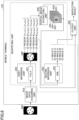
- FIG. 6 illustrates an example of the functional configuration of the functions related to inspection processing of the mobile terminal.
- the mobile terminal 120 includes an image data acquiring unit 610, a first inference unit 620, a partial image extracting unit 630, a second inference unit 640, and an output unit 650 as functions related to inspection processing.
- the first inference unit 620, the partial image extracting unit 630, and the second inference unit 640 function as identifying units for identifying environmental microorganisms in the image data.
- the image data acquiring unit 610 acquires image data 660 captured under visible light (for example, under fluorescent light) or under ultraviolet light in the inspection phase.
- the image data 660 is image data in which the preparation 240 is captured under visible light (for example, under fluorescent light) or under ultraviolet light.
- the first inference unit 620 includes a YOLO 621 that has completed learning (an example of the first model that has completed learning) generated by the first learning unit 510 performing learning processing on the YOLO 511 in the learning phase.
- the first inference unit 620 executes the YOLO 621 that has completed learning by inputting the image data 660 to the YOLO 621 that has completed learning.
- the YOLO 621 that has completed learning determines the position information of each region in the image data 660 and the attribute information of each region (whether or not environmental microorganisms are included, etc.).
- FIG. 6 illustrates that in the image data 660, the following are determined.
- the first inference unit 620 reports, to the partial image extracting unit 630 and the output unit 650, the position information of each region in the image data 660 and the attribute information of each region determined by the YOLO 621 that has completed learning.
- the partial image extracting unit 630 extracts image data (partial image data) of each region including environmental microorganisms in the image data 660 based on the position information of each region in the image data 660 and the attribute information of each region reported by the first inference unit 620.
- the example in FIG. 6 illustrates how the partial image extracting unit 630 extracts partial image data 631 to 635 of regions 1 to 5.
- the partial image extracting unit 630 reports, to the second inference unit 640, the extracted partial image data 631 to 635.
- the second inference unit 640 includes a DML 641 (a second model that has completed learning) generated by the second learning unit 520 performing learning processing on the DML 521 in the learning phase.
- the second inference unit 640 executes the DML 641 that has completed learning, by inputting partial image data 631 to 635 to the DML 641 that has completed learning.
- the DML 641 that has completed learning determines the type of environmental microorganism included in each piece of the partial image data 631 to 635.
- the example in FIG. 6 illustrates how the DML 641 that has completed learning determines "mold C" by inputting the partial image data 631, and the DML 641 that has completed learning determines "mold A” by inputting the partial image data 632.
- the example in FIG. 6 illustrates how the DML 641 that has completed learning determines "mold A” by inputting partial image data 633 and the DML 641 that has completed learning determines "mold B” by inputting partial image data 634.
- the example in FIG. 6 illustrates how the DML 641 that has completed learning determines "mold C" by inputting partial image data 635.
- the second inference unit 640 reports, to the output unit 650, the type of environmental microorganism determined by the DML 641 that has completed learning.
- the output unit 650 performs visualization processing based on the position information and attribute information of each region in the image data 660 reported by the first inference unit 620 and the type of environmental microorganism reported by the second inference unit 640 to generate the inspection result and display the inspection result on the display device 304.
- inspection result generated by the output unit 650 includes, for example:
- inspection in the inspection phase involves at least quantifying the types and numbers of environmental microorganisms.
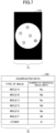
- FIG. 7 illustrates an example of inspection results provided by the mobile terminal.
- the notation of 7a indicates an example of image data 710 in which each region determined to include environmental microorganisms in the image data 660 is colored by the color according to the type of environmental microorganisms.
- the example of 7a in FIG. 7 illustrates how "mold C" is colored in blue, "mold A” is colored in red, and "mold C” is colored in yellow (in 7a of FIG. 7 , for convenience, the types are represented by different types of hatching).
- the notation of 7b indicates an example of aggregated data 720 in which the number of each type of environmental microorganism in the image data 660 is aggregated.
- aggregated data 720 includes "mold type” and "number” as items of information.
- "mold type” stores the names of six types of mold and other types ("other")
- "number” stores the number of the corresponding type of mold or the number of the other types.
- FIG. 8 is a flowchart illustrating the flow of learning processing.
- step S801 the experimenter 450 collects dust 160 from the air conditioner (indoor unit) 150 used for the experiment.
- step S802 the experimenter 450 disperses and dissolves the collected sample into a solution.
- step S803 the experimenter 450 classifies the solution by the type of environmental microorganism.
- step S804 the experimenter 450 takes a sample from each of the classified solutions and drops the sample on a slide glass to generate the preparations 180_1 to 180_6. Further, the experimenter 450 captures the generated preparation 180_1 to 180_6 (the imaging target) under visible light (for example, under fluorescent light) or ultraviolet light by using the mobile terminal 120.
- step S805 the image processing apparatus 140 generates learning data 441 to 446 for each type of environmental microorganism based on the captured image data.
- step S806 the image processing apparatus 140 uses the generated learning data 441 to 446 to perform learning processing on the YOLO to learn the position information and attribute information of each region in the image data.
- step S807 the image processing apparatus 140 uses the generated learning data 441 to 446 to perform learning processing on the DML to learn the types of environmental microorganisms in the partial image data of each region in the image data.
- FIG. 9 is a flowchart illustrating the flow of inspection processing.
- step S901 the service provider collects dust 220 from the air conditioner (indoor unit) 210 of the user to whom the inspection results are to be provided.
- step S902 the service provider disperses and dissolves the collected sample into a solution.
- step S903 the service provider takes a sample from the solution and drops the sample onto a slide glass to generate the preparation 240. Further, the service provider captures the generated preparation 240 (the imaging target) under visible or ultraviolet light by using the mobile terminal 120.
- step S904 the mobile terminal 120 determines position information and attribute information of each region in the captured image data, and extracts partial image data of each region determined to include environmental microorganisms.
- step S905 the mobile terminal 120 determines the type of environmental microorganism in each piece of the extracted partial image data.
- step S906 the mobile terminal 120 performs visualization processing based on the position information and attribute information of each region in the image data and the type information of environmental microorganisms, and provides the user with the inspection results.
- the mobile terminal 120 which is an example of the inspection system according to the first embodiment, performs the following.
- the mobile terminal which is an example of the inspection system, can accurately identify the environmental microorganisms in the captured image data even if the environmental microorganisms are similar in shape.
- an inspection system and an inspection method that reduce the time required to inspect environmental microorganisms can be provided.
- the first embodiment described above is a case where the mobile terminal 120 functions as an inspection system including the imaging device 121, the identifying unit (the second inference unit 640, etc.), and the output unit 650.
- some functions of the mobile terminal 120 may be arranged on the imaging table, and an inspection system may be formed by the imaging table and the mobile terminal 120.
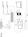
- FIG. 10 is a second diagram illustrating an application example of the inspection service providing system in the learning phase.
- the inspection service providing system 100 in the learning phase includes an inspection system 1010 and the image processing apparatus 140, and the inspection system 1010 includes an imaging table 1020 and the mobile terminal 120.
- the imaging table 1020 includes an imaging device 1021 and is connected to the mobile terminal 120.
- FIG. 11 is a second diagram illustrating an application example of the inspection service providing system in the inspection phase.
- the inspection service providing system 100 in the inspection phase includes an inspection system 1010, and the inspection system 1010 includes an imaging table 1020 and the mobile terminal 120.
- the imaging table 1020 has an imaging device 1021 and is connected to the mobile terminal 120.
- the imaging device 1021 is arranged on the imaging table 1020 and the mobile terminal 120 functions as an identifying unit and an output unit, the same effect as in the first embodiment can be obtained.
- the imaging device 1021 is arranged on the imaging table 1020, but other functions implemented in the mobile terminal 120 may be arranged on the imaging table 1020. That is, in the inspection system 1010 including the imaging table 1020 and the mobile terminal 120, any combination of function sharing between the imaging table 1020 and the mobile terminal 120 may be implemented.
- the method of providing inspection results is not limited to this and may be summarized in a form that is easy for the user to understand, for example, as a report.
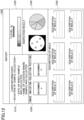
- FIG. 12 illustrates an example of a report including inspection results.
- a report 1200 includes, for example, the following information items.
- "user information” includes the date of collection, the name of the place where the sample was collected, etc., as the situation in which the sample was collected.
- image indicating the collection position includes an image indicating the location of collection, etc., as information indicating the environment in which the sample was collected.
- level indicates the level of contamination calculated based on the inspection result.
- a graph or the like illustrating the captured image data, the type and number (or ratio) of mold detected is inserted.
- the “description of mold” a detailed description of each type of mold (in the example in FIG. 12 , mold A to mold F) is included.
- the report 1200 may further include comparison results with past inspection results.
- Past inspection results referred to here include past inspection results of the same location and/or past inspection results of different collection positions.
- the size of the image data (partial image data) of each region determined to include environmental microorganisms is, for example, 32 ⁇ 32 pixels or more or 50 ⁇ 50 pixels or more.
- the location from which the dust is collected is not limited to the air conditioner (indoor unit) but may be other devices.
- Other devices include, for example, an air cleaner, a humidifier, a ventilation system, a blower, etc.
- the location from which the dust is collected is not limited to a device, but may be, for example, the surface of an object other than a device (walls, desks, indoor equipment, etc.) as long as the location is in an indoor environment.
- the inspection system according to the first and second embodiments described above is an inspection system for inspecting microorganisms or mold generated in an indoor environment or a device.
- the imaging target may be acquired by collecting dirt and dissolving the dirt into a solution.
- the imaging target may be acquired by acquiring the solution per se. That is, the imaging target may be any solution that can be obtained by sampling from an indoor environment or device.
- the learning process is performed by using the learning data 441 to 446, but the learning data used for the learning process is not limited to the learning data 441 to 446.
- the accuracy of identifying environmental microorganisms may be further improved by generating additional learning data and performing the learning process again.
- the types of environmental microorganisms are not limited to six types.
- Image data may be added to generate learning data corresponding to seven or more environmental microorganisms.
- six types of learning data were generated based on the number of types of environmental microorganisms.
- the system uses data manipulation language (DML), so that even if environmental microorganisms other than the six types are included, environmental microorganisms other than the six types can be accurately classified.
- DML data manipulation language
- mold is mentioned as an example of environmental microorganisms, but environmental microorganisms are not limited to mold.
- microorganisms such as bacteria may be used.
- bacteria include, for example, legionella genus, bacillus, micrococcus, etc.
- a saline solution including a surfactant is used when the collected sample is dissolved.
- the solution used when the collected sample is dissolved is not limited to this, and further, a solution diluted with a saline solution in which a surfactant is dissolved may be used. That is, the solution used when the collected sample is dissolved includes the following.
- the reason for diluting the solution with a saline solution in which surfactants are dissolved, is because detection accuracy can be improved by diluting the solution.
- the dilution ratio at this time is, for example, approximately 1 to 1000 times, preferably approximately 5 to 20 times.
- the output unit 650 is described as aggregating the number (or percentage) of each type of environmental microorganism in the image data 660.
- the number of each type of environmental microorganism may be counted, for example, by a DML that has completed learning.
Landscapes
- Engineering & Computer Science (AREA)
- Chemical & Material Sciences (AREA)
- Health & Medical Sciences (AREA)
- Life Sciences & Earth Sciences (AREA)
- General Health & Medical Sciences (AREA)
- Physics & Mathematics (AREA)
- General Physics & Mathematics (AREA)
- Analytical Chemistry (AREA)
- Biochemistry (AREA)
- Immunology (AREA)
- Theoretical Computer Science (AREA)
- Pathology (AREA)
- Organic Chemistry (AREA)
- Wood Science & Technology (AREA)
- Zoology (AREA)
- Dispersion Chemistry (AREA)
- Multimedia (AREA)
- Molecular Biology (AREA)
- Biomedical Technology (AREA)
- Bioinformatics & Cheminformatics (AREA)
- Computer Vision & Pattern Recognition (AREA)
- Medical Informatics (AREA)
- Microbiology (AREA)
- Genetics & Genomics (AREA)
- General Engineering & Computer Science (AREA)
- Biotechnology (AREA)
- Proteomics, Peptides & Aminoacids (AREA)
- Artificial Intelligence (AREA)
- Computing Systems (AREA)
- Databases & Information Systems (AREA)
- Evolutionary Computation (AREA)
- Software Systems (AREA)
- Nuclear Medicine, Radiotherapy & Molecular Imaging (AREA)
- Biophysics (AREA)
- Radiology & Medical Imaging (AREA)
- Quality & Reliability (AREA)
- Toxicology (AREA)
- Signal Processing (AREA)
- Sustainable Development (AREA)
- Apparatus Associated With Microorganisms And Enzymes (AREA)
Abstract
Description
- The present disclosure relates to an inspection system and inspection method.
- Conventionally, a service has been provided to inspect the presence or absence of and the type of environmental microorganisms (for example, mold) included in dust, etc., in air conditioners, and to provide the inspection results. By providing such a service, the service provider can make proposals (for example, cleaning air conditioners and changing filters of air conditioners, etc.) to realize an optimal air environment according to the inspection results.
-
- (Patent document 1)
Japanese Unexamined Patent Application Publication No. 2007-195454 - (Patent document 2)
Japanese Translation of PCT International Application Publication No. 2020-529869 WO 2019/074926 - However, in order to inspect the presence or absence of and the type of environmental microorganisms, a culture method in which collected samples (such as dust including environmental microorganisms) are cultured in a culture medium has been used, which has taken time to provide the inspection results.
- The present disclosure provides an inspection system and inspection method that reduce the time required to inspect environmental microorganisms.
- The first aspect of the present disclosure is an inspection system for inspecting a microorganism or mold that is generated in an indoor environment or a device, the inspection system including
- an imaging unit configured to directly capture a sample collected from the indoor environment or the device; and
- an output unit configured to inspect the microorganism or the mold in image data captured by the imaging unit, and output an inspection result.
- According to the first aspect of the present disclosure, an inspection system that reduces the time required to inspect environmental microorganisms can be provided.
- Further, the second aspect of the present disclosure is an inspection system for inspecting a microorganism or mold that is generated in an indoor environment or a device, the inspection system including
- an imaging unit configured to capture an appearance of an individual unit of the microorganism or the mold collected from the indoor environment or the device; and
- an output unit configured to inspect the microorganism or the mold in image data captured by the imaging unit, and output an inspection result.
- According to the second aspect of the present disclosure, an inspection system that reduces the time required to inspect environmental microorganisms can be provided.
- Further, the third aspect of the present disclosure is the inspection system according to the first or second aspect, wherein
- an imaging target captured by the imaging unit is a solution collected from the indoor environment or the device, and
- the imaging unit captures the imaging target through a lens under visible light or ultraviolet light.
- Further, the fourth aspect of the present disclosure is the inspection system according to the third aspect, wherein the solution can be obtained by dissolving, in the solution, the sample collected from the indoor environment or the device.
- Further, the fifth aspect of the present disclosure is the inspection system according to the third aspect, wherein the imaging target is collected from any of an air conditioner, an air cleaner, a humidifier, a ventilation system, a blower, or a surface of the indoor environment.
- Further, the sixth aspect of the present disclosure is the inspection system according to the third aspect, further including a first model that has completed learning configured to determine an attribute of each region in the image data.
- Further, the seventh aspect of the present disclosure is the inspection system according to the sixth aspect, further including a second model that has completed learning configured to determine a type of the microorganism or the mold, with respect to the region determined to include the microorganism or the mold by the first model that has completed learning.
- Further, the eighth aspect of the present disclosure is the inspection system according to any one of the first to seventh aspects, wherein the output unit aggregates a number of the microorganism or the mold for each type of the microorganism or the mold in the image data captured by the imaging unit, and outputs the aggregated number.
- Further, the ninth aspect of the present disclosure is an inspection system for inspecting a microorganism or mold that is generated in an indoor environment or a device, the inspection system including
- an imaging unit configured to directly capture a sample collected from the indoor environment or the device; and
- an output unit configured to inspect the microorganism or the mold in image data captured by the imaging unit, and output an inspection result, wherein
- the output unit displays, as the inspection result, a type of the microorganism or the mold, a ratio of the microorganism or the mold, and the image data captured by the imaging unit, and also displays any one of information indicating the indoor environment or the device, a description of the microorganism or the mold, a level of contamination, and a result of comparison with another inspection result.
- Further, the tenth aspect of the present disclosure is an inspection system for inspecting a microorganism or mold that is generated in an indoor environment or a device, the inspection system including
- an imaging unit configured to capture an appearance of an individual unit of the microorganism or the mold collected from the indoor environment or the device; and
- an output unit configured to inspect the microorganism or the mold in image data captured by the imaging unit, and output an inspection result, wherein
- the output unit displays, as the inspection result, a type of the microorganism or the mold, a ratio of the microorganism or the mold, and the image data captured by the imaging unit, and also displays any one of information indicating the indoor environment or the device, a description of the microorganism or the mold, a level of contamination, and a result of comparison with another inspection result.
- Further, the eleventh aspect of the present disclosure is the inspection system according to any one of the third to seventh aspects, wherein the imaging target is obtained by dispersing and dissolving the collected sample in the solution.
- Further, the twelfth aspect of the present disclosure is the inspection system according to the eleventh aspect, wherein the imaging target is obtained by dispersing and dissolving, in the solution, the sample collected from an air conditioner.
- Further, the thirteenth aspect of the present disclosure is the inspection system according to the eleventh or twelfth aspect, wherein the imaging target is obtained by dispersing and dissolving the collected sample in a saline solution in which a surfactant is dissolved.
- Further, the fourteenth aspect of the present disclosure is the inspection system according to any one of the eleventh to thirteenth aspects, wherein the imaging target includes a first solution obtained by dispersing and dissolving the collected sample in a saline solution in which a surfactant is dissolved, and a second solution obtained by further diluting the first solution by using a saline solution in which a surfactant is dissolved.
- Further, the fifteenth aspect of the present disclosure is the inspection system according to the seventh aspect, wherein each of the regions, for which the attribute is determined by the first model that has completed learning, is 32 pixels × 32 pixels or more.
- Further, the sixteenth aspect of the present disclosure is the inspection system according to the seventh aspect, wherein the first model that has completed learning is generated by performing learning processing by using learning data, wherein
in the learning data, - the image data including a same type of the microorganism or the mold, and
- position information in which a position of each of the regions determined to include the microorganism or the mold in the image data is identified by a plurality of coordinates, are associated with each other.
- Further, the seventeenth aspect of the present disclosure is the inspection system according to the seventh aspect, wherein when the type of the microorganism or the mold is determined, the second model that has completed learning counts a number of the microorganism or the mold for each determined type.
- Further, the eighteenth aspect of the present disclosure is the inspection system according to any one of the first to seventeenth aspects, wherein the inspection system is a mobile terminal, and the imaging unit is built in the mobile terminal.
- Further, the nineteenth aspect of the present disclosure is the inspection system according to the seventh aspect, further including
- a portable imaging table on which the imaging target is mounted, and
- a mobile terminal connected to the imaging table, wherein
- the imaging table includes the imaging unit, and
- the mobile terminal includes the first model that has completed learning, the second model that has completed learning, and the output unit.
- Further, the twentieth aspect of the present disclosure is the inspection system according to any one of the seventh, fifteenth, and sixteenth aspects , wherein the first model that has completed learning is a YOLO that has completed learning.
- Further, the twenty-first aspect of the present disclosure is the inspection system according to the seventh or seventeenth aspect, wherein
- the second model that has completed learning is generated by performing learning processing by using learning data, wherein
- in the learning data,
- partial image data of each of the regions determined to include the microorganism or the mold in the image data including a same type of the microorganism or the mold, and
- the type of the microorganism or the mold, are associated with each other.
- Further, the twenty-second aspect of the present disclosure is the inspection system according to any one of the seventh, seventeenth, and twenty-first aspects, wherein the second model that has completed learning is a DML that has completed learning.
- Further, the twenty-third aspect of the present disclosure is an inspection method performed by an inspection system for inspecting a microorganism or mold that is generated in an indoor environment or a device, the inspection method including
an imaging step of directly capturing a sample collected from the indoor environment or the device; and
an output step of inspecting the microorganism or the mold in captured image data, and outputting an inspection result. - Further, the twenty-fourth aspect of the present disclosure is an inspection method performed by an inspection system for inspecting a microorganism or mold that is generated in an indoor environment or a device, the inspection method including
- an imaging step of capturing an appearance of an individual unit of the microorganism or the mold collected from the indoor environment or the device; and
- an output step of inspecting the microorganism or the mold in captured image data, and outputting an inspection result.
-
- [
FIG. 1] FIG. 1 is a first diagram illustrating an application example of the inspection service providing system in the learning phase. - [
FIG. 2] FIG. 2 is a first diagram illustrating an application example of the inspection service providing system in the inspection phase. - [
FIG. 3] FIG. 3 is a diagram illustrating an example of the hardware configuration of a mobile terminal and an image processing apparatus. - [
FIG. 4] FIG. 4 is a diagram illustrating an example of the functional configuration of a function related to learning data generation processing of an image processing apparatus. - [
FIG. 5] FIG. 5 is a diagram illustrating an example of the functional configuration of a function related to learning processing of an image processing apparatus. - [
FIG. 6] FIG. 6 is a diagram illustrating an example of the functional configuration of a function related to inspection processing of a mobile terminal. - [
FIG. 7] FIG. 7 is a diagram illustrating an example of provision of inspection results by a mobile terminal. - [
FIG. 8] FIG. 8 is a flowchart illustrating the flow of the learning processing. - [
FIG. 9] FIG. 9 is a flowchart illustrating the flow of the inspection processing. - [
FIG. 10] FIG. 10 is a second diagram illustrating an application example of the inspection service providing system in the learning phase. - [
FIG. 11] FIG. 11 is a second diagram illustrating an application example of the inspection service providing system in the inspection phase. - [
FIG. 12] FIG. 12 is a diagram illustrating an example of a report including inspection results. - Each embodiment will be described below with reference to the accompanying drawings. In the present specification and drawings, with respect to elements having substantially the same functional configuration, the same symbols are applied and overlapping descriptions are omitted.
- First, an application example of an inspection service providing system in the learning phase, among the inspection service providing systems including the inspection system according to the first embodiment, will be described.
FIG. 1 is a first diagram illustrating an application example of the inspection service providing system in the learning phase. As illustrated inFIG. 1 , in the learning phase, an inspectionservice providing system 100 includes a mobile terminal 120 (an example of the inspection system according to the first embodiment), an imaging table 130, and animage processing apparatus 140. - In the learning phase, the imaging target captured by using the
mobile terminal 120 is acquired by the following procedures and is directly captured under visible light (for example, under fluorescent light) or ultraviolet light. - (1) An experimenter takes a sample (dust 160) from an air conditioner (indoor unit) 150 subjected to an experiment (the
dust 160 may be collected from the inside of the air conditioner (indoor unit) 150 or from the outside surface of the air conditioner (indoor unit) 150). - (2) The collected sample is dispersed and dissolved in a
saline solution 170 including dissolved surfactants. In this case, "dispersing and dissolving the sample in a solution" may include "drying the sample that is dispersed and dissolved in the solution". - (3) The sample dissolved in the solution is taken from the solution 170 (for example, 10 microliters) and dropped on a glass slide to generate a preparation. At this time, each of the samples 181_1 to 181_6 is taken so that only the same type of environmental microorganisms are included in each sample, and by dropping each type on a different glass slide, the preparations 180_1 to 180_6 are generated. The example in
FIG. 1 illustrates a case in which a sample (the dust 160) collected from an air conditioner (indoor unit) 150 has included six types of environmental microorganisms. - (4) The generated preparations 180_1 to 180_6 are sequentially mounted on the imaging table 130 as imaging targets, and are captured under visible light (for example, under fluorescent light) or ultraviolet light by using the
mobile terminal 120. - That is, in the learning phase, "directly capture" means that the procedures from sample collection (1) to imaging (4) do not include "culturing of environmental microorganisms" (image capturing is performed without increasing the number of environmental microorganisms from the time the sample is collected). Further, "image capturing" means obtaining information about the appearance (color and shape) of an individual unit of environmental microorganism (in the case of mold, an individual unit of mold, specifically, one unit of spores and hyphae; in the case of bacteria, an individual unit of bacteria).
- The imaging table 130 is configured to be portable and includes a lens 131, a mounting
part 132, and a lens support part 133 as illustrated inFIG. 1 . - The lens 131 enlarges the imaging target (in the example in
FIG. 1 , the preparation 180_1) to a predetermined magnification. - The mounting
part 132 is a member on which an imaging target (in the example inFIG. 1 , the preparation 180_1) is mounted. - The lens support part 133 is a member for supporting the lens 131 at a position separated by a predetermined distance from the imaging target mounted on the mounting
part 132, and is a member on which themobile terminal 120 is mounted on the upper surface. The lens support part 133 may be provided with a lifting mechanism for varying the distance between the imaging target mounted on the mountingpart 132 and the lens 131. - The
mobile terminal 120 includes a built-in imaging device 121 (an example of an imaging unit) and is mounted on the lens support part 133 so that the position of the lens 131 coincides with the position of theimaging device 121 to capture the imaging target (in the example inFIG. 1 , the preparation 180_1) under visible light. - Further, in the learning phase, the
mobile terminal 120 transmits the captured image data 122_1 to theimage processing apparatus 140. - The
image processing apparatus 140 generates learning data based on image data 122_1 transmitted from themobile terminal 120. Further, theimage processing apparatus 140 uses the generated learning data to perform learning processing with respect to the learning model and generates a model that has completed learning. The model that has completed learning generated in the learning phase is installed in themobile terminal 120 in the inspection phase. - Next, an application example of the inspection service providing system in the inspection phase, among the inspection service providing systems including the inspection system according to the first embodiment, will be described.
FIG. 2 is a first diagram illustrating an application example of the inspection service providing system in the inspection phase. As illustrated inFIG. 2 , in the inspection phase, the inspectionservice providing system 100 includes the mobile terminal 120 (an example of the inspection system according to the first embodiment) and the imaging table 130. - In the inspection phase, the imaging target captured by using the
mobile terminal 120 is acquired by the following procedures and is captured directly under visible light (for example, under fluorescent light) or ultraviolet light. - (1) A sample (dust 220) is collected from an air conditioner (indoor unit) 210 of the user to whom the service provider provides the inspection results (the results may be collected from the inside of the air conditioner (indoor unit) 210 or from the outside surface of the air conditioner (indoor unit) 210).
- (2) The collected sample is dispersed and dissolved in a
saline solution 230 including dissolved surfactants. In this case, "dispersing and dissolving the sample in a solution" may include " drying the sample that is dispersed and dissolved in the solution". - (3) The
sample 241 dissolved in the solution is taken from the solution 230 (for example, 10 microliters) and dropped on a glass slide to generate apreparation 240. - (4) The generated
preparation 240 is mounted on the imaging table 130 as an imaging target, and is captured under visible light (for example, under fluorescent light) or under ultraviolet light by using themobile terminal 120. - That is, in the inspection phase, "directly capture" means that the procedures from sample collection (1) to imaging (4) do not include "culturing of environmental microorganisms" (image capturing is performed without increasing the number of environmental microorganisms from the time the sample is collected). Further, "image capturing" means obtaining information about the appearance (color and shape) of an individual unit of environmental microorganism (in the case of mold, an individual unit of mold, specifically, one unit of spores and hyphae; in the case of bacteria, an individual unit of bacteria).
- As illustrated in
FIG. 2 , the imaging table 130 includes the lens 131, the mountingpart 132, and the lens support part 133. The imaging table 130 used in the inspection phase is the same as the imaging table 130 used in the learning phase (FIG. 1 ), and, therefore, a detailed description of each part is omitted here. - The
mobile terminal 120 includes a built-inimaging device 121 and is mounted on the lens support part 133 so that the position of the lens 131 coincides with the position of theimaging device 121 to capture an imaging target (in the example inFIG. 2 , the preparation 240) under visible light (for example, under fluorescent light) or ultraviolet light. - In the inspection phase, the model that has completed learning is installed in the
mobile terminal 120, and the capturedimage data 250 is processed by using the model that has completed learning to provide theinspection result 260. - Thus, by using the model that has completed learning to inspect the presence or absence, the types, etc., of environmental microorganisms, according to the inspection
service providing system 100, the following effects can be achieved. - Even with respect to environmental microorganisms that are similar in shape regardless of type, such as mold (a member of the kingdom of fungi, especially yeast and ascomycetes), the environmental microorganisms can be accurately identified in the captured image data.
- Because no culture method is required, it is possible to shorten the time required to provide inspection results, and for example, when a service provider visits a user to whom inspection results are to be provided, it is possible to collect samples from the user's air conditioner and provide the inspection results on the spot. As a result, it is possible to immediately make proposals (such as cleaning the air conditioner and replacing the filter) to realize an optimal air environment according to the inspection results.
- Because no culture method is required, it is possible to reduce the cost of providing the inspection results (eliminating the need to hire a specialist).
- Because no culture method is required, dead environmental microorganisms (that is, not only live bacteria but also dead bacteria) can also be identified (eliminating the need to collect live environmental microorganisms).
- Next, the hardware configuration of the
mobile terminal 120 and theimage processing apparatus 140 will be described.FIG. 3 illustrates an example of the hardware configuration of the mobile terminal and the image processing apparatus. - In
FIG. 3 , the notation of 3a indicates an example of a hardware configuration of themobile terminal 120. As illustrated in 3a inFIG. 3 , themobile terminal 120 has includes aprocessor 301, amemory 302, anauxiliary storage device 303, adisplay device 304, anoperation device 305, acommunication device 306, and theimaging device 121. Each piece of hardware of themobile terminal 120 is connected to each other via abus 307. - The
processor 301 includes various computing devices such as a CPU (Central Processing Unit) and a GPU (Graphics Processing Unit). Theprocessor 301 reads various programs (for example, in the inspection phase, an inspection program, etc.) into thememory 302 and executes the programs. - The
memory 302 includes a main storage device such as a ROM (Read Only Memory) and a RAM (Random Access Memory). Theprocessor 301 and thememory 302 form what is referred to as computer, and theprocessor 301 executes various programs read on thememory 302, and the computer implements various functions. - The
auxiliary storage device 303 stores various programs and various types of data used when various programs are executed by theprocessor 301. - The
display device 304 is a display device for displaying the captured image data 122_1, 250, the inspection results 260, etc. Theoperation device 305 is an input device used for inputting various instructions to themobile terminal 120. - The
communication device 306 is, for example, a communication device for communicating with theimage processing apparatus 140. Theimaging device 121 captures the preparations 180_1 to 180_6 and 240 that are imaging targets. - Various programs installed in the
auxiliary storage device 303 are installed, for example, by being downloaded from a network via thecommunication device 306. - In
FIG. 3 , the notation of 3b indicates an example of a hardware configuration of theimage processing apparatus 140. The hardware configuration of theimage processing apparatus 140 is almost the same as that of themobile terminal 120, and, therefore, the differences from themobile terminal 120 will be mainly described here. - A
processor 321 reads and executes, for example, a learning program or the like on thememory 322. Anauxiliary storage device 323 implements, for example, a learning data storage unit (to be described later). - A
drive device 327 is a device for setting arecording medium 329. Therecording medium 329 here includes media for recording information optically, electrically, or magnetically, such as a CD-ROM, a flexible disk, a magneto-optical disk, etc. Therecording medium 329 may also include a semiconductor memory, etc., for electrically recording information, such as a ROM, flash memory, etc. - Various programs installed in the
auxiliary storage device 323 are installed, for example, when the distributedrecording medium 329 is set in thedrive device 327 and various programs recorded in therecording medium 329 are read by thedrive device 327. Alternatively, various programs installed in theauxiliary storage device 323 may be installed by being downloaded from the network via thecommunication device 326. - Next, the functional configuration of the
image processing apparatus 140 will be described. As described above, a learning program is installed in theimage processing apparatus 140, and when the program is executed, theimage processing apparatus 140 implements the following functions. - Functions related to learning data generation processing for generating learning data
- Functions related to learning processing for performing learning processing with respect to a learning model by using learning data, etc.
- In the following, these functions implemented by the
image processing apparatus 140 will be explained separately. - First, the functions related to the learning data generation processing are described.
FIG. 4 illustrates an example of the functional configuration of the functions related to the learning data generation processing of the image processing apparatus. As illustrated inFIG. 4 , theimage processing apparatus 140 includes an imagedata acquiring unit 410, a correctlabel acquiring unit 420, and a learningdata generating unit 430 as functions related to the learning data generation processing. - The image
data acquiring unit 410 acquires image data 122_1 to 122_6 captured under visible light (for example, under fluorescent light) or under ultraviolet light by themobile terminal 120 in the learning phase. The image data 122_1 to 122_6 is image data respectively obtained by capturing the preparation 180_1 to 180_6 under visible light (for example, under fluorescent light) or under ultraviolet light. - The correct
label acquiring unit 420 acquires the correct label input by anexperimenter 450. Theexperimenter 450 inputs the type of environmental microorganism included in each sample 181_1 to 181_6 of the preparation 180_1 to 180_6 to theimage processing apparatus 140 as correct data, and the correctlabel acquiring unit 420 acquires the correct data. - In the present embodiment, the
experimenter 450 inputs "mold A" as the type of environmental microorganism included in the sample 181_1 and inputs "mold B" as the type of environmental microorganism included in the sample 181_2. Further, theexperimenter 450 inputs "mold C" as the type of environmental microorganism included in the sample 181_3 and inputs "mold D" as the type of environmental microorganism included in the sample 181_4. Further, theexperimenter 450 inputs "mold E" as the type of environmental microorganism included in the sample 181_5 and inputs "mold F" as the type of environmental microorganism included in the sample 181_6. - The learning
data generating unit 430 generates learning data by associating the image data 122_1 to 122_6 acquired by the imagedata acquiring unit 410 with the corresponding types of environmental microorganisms ("mold A" to "mold F") acquired by the correctlabel acquiring unit 420. Further, the learningdata generating unit 430 also stores the generated learning data in the learningdata storage unit 440. - In
FIG. 4 , the learningdata 441 to 446 indicates the learning data generated by the learningdata generating unit 430 and stored in a learningdata storage unit 440. As illustrated inFIG. 4 , the learningdata 441 to 446 includes "image data", "image region", "partial image", and "correct label" as items of information. - Among these, the file name of the image data acquired by the image
data acquiring unit 410 is stored in the "image data". In the example ofFIG. 4 , "image data 1" to "image data 6" are the file names of the image data 122_1 to 122_6, respectively. - The "image region" stores position information (multiple sets of (x-coordinate, y-coordinate), such as (x-coordinate, y-coordinate) of two opposite vertices of a region) of each region determined to include one environmental microorganism in the image data. In the case of
FIG. 4 , for example, "region 1-1" (= coordinates (x11a, y11a), (x11b, y11b)) is stored. - The file name of the image data (partial image data) of each region determined to include one environmental microorganism in the image data, identified by the "image region", is stored in the "partial image". Incidentally, including one environmental microorganism means, for example, including one spore unit in the case where the environmental microorganism is a mold.
- The "correct label" stores the type of environmental microorganism in each region identified by the "image region". In the case of the example in
FIG. 4 , "mold A" to "mold F" are stored from the "correct label" of the learningdata 441 to the "correct label" of the learningdata 446, respectively. - Next, functions related to the learning processing will be described.
FIG. 5 is a diagram illustrating an example of the functional configuration of the functions related to the learning processing of the image processing apparatus. As illustrated inFIG. 5 , theimage processing apparatus 140 includes afirst learning unit 510 and asecond learning unit 520 as the functions related to learning processing. - The
first learning unit 510 learns the processing for determining the region including environmental microorganism in the image data. Specifically, thefirst learning unit 510 includes theYOLO 511 and a comparison/change unit 512. - The
YOLO 511 is a learning model that determines the position information of each region in the image data and the attribute information of each region (whether the region includes an environmental microorganism, etc.) by taking the image data of the file name identified by the "image data" as an input in the learning data. - The comparison/
change unit 512 compares the position information of each region and the attribute information of each region determined by theYOLO 511 with the position information of each region determined to include the environmental microorganism identified by the "image region" of the learning data and calculates the error. Further, the comparison/change unit 512 back-propagates the calculated error and updates the model parameters of theYOLO 511. - For example, in the case of the learning
data 441, the comparison/change unit 512 compares - the position information of each region and the attribute information of each region that is output from the
YOLO 511 by inputting image data 122_1 of file name = "image data 1" into theYOLO 511, with - the position information of each region determined to include environmental microorganisms identified by image region = "region 1-1", "region 1-2", "region 1-3", ··· ,
- The
second learning unit 520 learns the process of determining the type of environmental microorganism from the image data (partial image data) of each region determined to include the environmental microorganism in the image data. Specifically, thesecond learning unit 520 includes Deep Metric Learning (DML) 521 and a comparison/change unit 522. - In learning data, the
DML 521 is a learning model that outputs the types of environmental microorganisms (in the present embodiment, six types) (outputs six types of classification probabilities) by using partial image data identified by a "partial image" as input. - The comparison/
change unit 522 compares the type of environmental microorganism determined by theDML 521 with (classification probability (for example, 1.0) of) the type of environmental microorganism identified by a "correct label" in the learning data and calculates the error. Further, the comparison/change unit 522 back-propagates the calculated error and updates the model parameters of theDML 521. - For example, in the case of the learning
data 441, the comparison/change unit 522 compares - the type of environmental microorganism determined by the
DML 521 by inputting the partial image data of the file name = "image 1-1" into theDML 521, with - correct label = "mold A",
- Next, the functional configuration of the
mobile terminal 120 will be described. As described above, an inspection program is installed in themobile terminal 120, and when the program is executed, the function related to inspection processing is implemented by themobile terminal 120. Therefore, the following describes the function related to inspection processing implemented by themobile terminal 120. -
FIG. 6 illustrates an example of the functional configuration of the functions related to inspection processing of the mobile terminal. As illustrated inFIG. 6 , themobile terminal 120 includes an imagedata acquiring unit 610, afirst inference unit 620, a partialimage extracting unit 630, asecond inference unit 640, and anoutput unit 650 as functions related to inspection processing. Thefirst inference unit 620, the partialimage extracting unit 630, and thesecond inference unit 640 function as identifying units for identifying environmental microorganisms in the image data. - The image
data acquiring unit 610 acquiresimage data 660 captured under visible light (for example, under fluorescent light) or under ultraviolet light in the inspection phase. Theimage data 660 is image data in which thepreparation 240 is captured under visible light (for example, under fluorescent light) or under ultraviolet light. - The
first inference unit 620 includes aYOLO 621 that has completed learning (an example of the first model that has completed learning) generated by thefirst learning unit 510 performing learning processing on theYOLO 511 in the learning phase. Thefirst inference unit 620 executes theYOLO 621 that has completed learning by inputting theimage data 660 to theYOLO 621 that has completed learning. With this, theYOLO 621 that has completed learning determines the position information of each region in theimage data 660 and the attribute information of each region (whether or not environmental microorganisms are included, etc.). - The example in
FIG. 6 illustrates that in theimage data 660, the following are determined. - Coordinates (x1a, y1a), (x1b, y1b) are determined as position information of
region 1, and it is determined that this region includes environmental microorganisms. - Coordinates (x2a, y2a), (x2b, y2b) are determined as position information of
region 2, and it is determined that this region includes environmental microorganisms. - Coordinates (x3a, y3a), (x3b, y3b) are determined as position information of
region 3, and it is determined that this region includes environmental microorganisms. - Coordinates (x4a, y4a), (x4b, y4b) are determined as position information of
region 4, and it is determined that this region includes environmental microorganisms. - Coordinates (x5a, y5a), (x5b, y5b) are determined as position information of
region 5, and it is determined that this region includes environmental microorganisms. - It is determined that regions other than
regions 1 to 5 do not include environmental microorganisms. - Note that the
first inference unit 620 reports, to the partialimage extracting unit 630 and theoutput unit 650, the position information of each region in theimage data 660 and the attribute information of each region determined by theYOLO 621 that has completed learning. - The partial
image extracting unit 630 extracts image data (partial image data) of each region including environmental microorganisms in theimage data 660 based on the position information of each region in theimage data 660 and the attribute information of each region reported by thefirst inference unit 620. The example inFIG. 6 illustrates how the partialimage extracting unit 630 extractspartial image data 631 to 635 ofregions 1 to 5. - The partial
image extracting unit 630 reports, to thesecond inference unit 640, the extractedpartial image data 631 to 635. - The
second inference unit 640 includes a DML 641 (a second model that has completed learning) generated by thesecond learning unit 520 performing learning processing on theDML 521 in the learning phase. Thesecond inference unit 640 executes theDML 641 that has completed learning, by inputtingpartial image data 631 to 635 to theDML 641 that has completed learning. Thus, theDML 641 that has completed learning determines the type of environmental microorganism included in each piece of thepartial image data 631 to 635. - The example in
FIG. 6 illustrates how theDML 641 that has completed learning determines "mold C" by inputting thepartial image data 631, and theDML 641 that has completed learning determines "mold A" by inputting thepartial image data 632. The example inFIG. 6 illustrates how theDML 641 that has completed learning determines "mold A" by inputtingpartial image data 633 and theDML 641 that has completed learning determines "mold B" by inputtingpartial image data 634. Furthermore, the example inFIG. 6 illustrates how theDML 641 that has completed learning determines "mold C" by inputtingpartial image data 635. - Note that the
second inference unit 640 reports, to theoutput unit 650, the type of environmental microorganism determined by theDML 641 that has completed learning. - The
output unit 650 performs visualization processing based on the position information and attribute information of each region in theimage data 660 reported by thefirst inference unit 620 and the type of environmental microorganism reported by thesecond inference unit 640 to generate the inspection result and display the inspection result on thedisplay device 304. - Note that the inspection result generated by the
output unit 650 includes, for example: - image data in which each region determined to include environmental microorganism in the
image data 660 is colored by the color according to the type of environmental microorganism, - aggregate data totaling the number (or percentage) of each type of environmental microorganisms in the
image data 660, etc. - Thus, "inspection" in the inspection phase involves at least quantifying the types and numbers of environmental microorganisms.
- Next, an example of inspection results provided by the
mobile terminal 120 will be described.FIG. 7 illustrates an example of inspection results provided by the mobile terminal. - In
FIG. 7 , the notation of 7a indicates an example ofimage data 710 in which each region determined to include environmental microorganisms in theimage data 660 is colored by the color according to the type of environmental microorganisms. The example of 7a inFIG. 7 illustrates how "mold C" is colored in blue, "mold A" is colored in red, and "mold C" is colored in yellow (in 7a ofFIG. 7 , for convenience, the types are represented by different types of hatching). - In
FIG. 7 , the notation of 7b indicates an example of aggregateddata 720 in which the number of each type of environmental microorganism in theimage data 660 is aggregated. As illustrated in 7b inFIG. 7 , aggregateddata 720 includes "mold type" and "number" as items of information. Among these, "mold type" stores the names of six types of mold and other types ("other"), and "number" stores the number of the corresponding type of mold or the number of the other types. - Next, the flow of learning processing by the inspection
service providing system 100 will be described.FIG. 8 is a flowchart illustrating the flow of learning processing. - In step S801, the
experimenter 450 collectsdust 160 from the air conditioner (indoor unit) 150 used for the experiment. - In step S802, the
experimenter 450 disperses and dissolves the collected sample into a solution. - In step S803, the
experimenter 450 classifies the solution by the type of environmental microorganism. - In step S804, the
experimenter 450 takes a sample from each of the classified solutions and drops the sample on a slide glass to generate the preparations 180_1 to 180_6. Further, theexperimenter 450 captures the generated preparation 180_1 to 180_6 (the imaging target) under visible light (for example, under fluorescent light) or ultraviolet light by using themobile terminal 120. - In step S805, the
image processing apparatus 140 generates learningdata 441 to 446 for each type of environmental microorganism based on the captured image data. - In step S806, the
image processing apparatus 140 uses the generated learningdata 441 to 446 to perform learning processing on the YOLO to learn the position information and attribute information of each region in the image data. - In step S807, the
image processing apparatus 140 uses the generated learningdata 441 to 446 to perform learning processing on the DML to learn the types of environmental microorganisms in the partial image data of each region in the image data. - Next, the flow of inspection processing by the inspection
service providing system 100 will be described.FIG. 9 is a flowchart illustrating the flow of inspection processing. - In step S901, the service provider collects
dust 220 from the air conditioner (indoor unit) 210 of the user to whom the inspection results are to be provided. - In step S902, the service provider disperses and dissolves the collected sample into a solution.
- In step S903, the service provider takes a sample from the solution and drops the sample onto a slide glass to generate the
preparation 240. Further, the service provider captures the generated preparation 240 (the imaging target) under visible or ultraviolet light by using themobile terminal 120. - In step S904, the
mobile terminal 120 determines position information and attribute information of each region in the captured image data, and extracts partial image data of each region determined to include environmental microorganisms. - In step S905, the
mobile terminal 120 determines the type of environmental microorganism in each piece of the extracted partial image data. - In step S906, the
mobile terminal 120 performs visualization processing based on the position information and attribute information of each region in the image data and the type information of environmental microorganisms, and provides the user with the inspection results. - As is clear from the above description, the
mobile terminal 120, which is an example of the inspection system according to the first embodiment, performs the following. - The collected dust is dissolved into a solution, and the preparation generated by dropping the solution onto the slide glass is captured as an imaging target through a lens under visible or ultraviolet light. That is, the dust is captured directly or the appearance of an environmental microorganism is captured.
- The environmental microorganisms in the captured image data are identified by using the YOLO that has completed learning to determine the attributes of each region in the image data, and by using the DML that has completed learning to determine the type of environmental microorganism for the regions determined to include the environmental microorganisms.
- The visualization process is performed on the environmental microorganisms in the identified image data and the inspection results are provided.
- Thus, by using the model that has completed learning to identify the environmental microorganisms in the image data, the mobile terminal, which is an example of the inspection system, can accurately identify the environmental microorganisms in the captured image data even if the environmental microorganisms are similar in shape.
- This eliminates the need for culture methods and reduces the time required to provide inspection results. As a result, for example, when a service provider visits a user to whom inspection results are to be provided, a sample can be collected from the user's air conditioner and the inspection results can be provided on the spot.
- That is, according to the first embodiment, an inspection system and an inspection method that reduce the time required to inspect environmental microorganisms, can be provided.
- The first embodiment described above is a case where the
mobile terminal 120 functions as an inspection system including theimaging device 121, the identifying unit (thesecond inference unit 640, etc.), and theoutput unit 650. However, some functions of themobile terminal 120 may be arranged on the imaging table, and an inspection system may be formed by the imaging table and themobile terminal 120. -
FIG. 10 is a second diagram illustrating an application example of the inspection service providing system in the learning phase. The difference fromFIG. 1 is that in the case of the second embodiment, the inspectionservice providing system 100 in the learning phase includes aninspection system 1010 and theimage processing apparatus 140, and theinspection system 1010 includes an imaging table 1020 and themobile terminal 120. The difference fromFIG. 1 is that in the case of the second embodiment, the imaging table 1020 includes animaging device 1021 and is connected to themobile terminal 120. - Similarly,
FIG. 11 is a second diagram illustrating an application example of the inspection service providing system in the inspection phase. The difference fromFIG. 2 is that in the case of the second embodiment, the inspectionservice providing system 100 in the inspection phase includes aninspection system 1010, and theinspection system 1010 includes an imaging table 1020 and themobile terminal 120. The difference fromFIG. 2 is that in the case of the second embodiment, the imaging table 1020 has animaging device 1021 and is connected to themobile terminal 120. - Thus, even if the
imaging device 1021 is arranged on the imaging table 1020 and themobile terminal 120 functions as an identifying unit and an output unit, the same effect as in the first embodiment can be obtained. - In the present embodiment, the
imaging device 1021 is arranged on the imaging table 1020, but other functions implemented in themobile terminal 120 may be arranged on the imaging table 1020. That is, in theinspection system 1010 including the imaging table 1020 and themobile terminal 120, any combination of function sharing between the imaging table 1020 and themobile terminal 120 may be implemented. - In the first and second embodiment described above, at least the type and the number of environmental microorganisms and image data are output as examples of the providing inspection results, but the method of providing inspection results is not limited to this and may be summarized in a form that is easy for the user to understand, for example, as a report.
-
FIG. 12 illustrates an example of a report including inspection results. As illustrated inFIG. 12 , areport 1200 includes, for example, the following information items. - "user information" (reference numeral 1210)
- "image indicating the collection position" (reference numeral 1220)
- "level" (reference numeral 1230)
- "inspection result" (reference numeral 1240)
- "description of mold" (reference numeral 1250)
- Among these, "user information" includes the date of collection, the name of the place where the sample was collected, etc., as the situation in which the sample was collected. Further, "image indicating the collection position" includes an image indicating the location of collection, etc., as information indicating the environment in which the sample was collected. Further, "level" indicates the level of contamination calculated based on the inspection result. Further, in the "inspection result", a graph or the like illustrating the captured image data, the type and number (or ratio) of mold detected is inserted. Furthermore, in the "description of mold", a detailed description of each type of mold (in the example in
FIG. 12 , mold A to mold F) is included. - Note that although not illustrated in the
report 1200 inFIG. 12 , thereport 1200 may further include comparison results with past inspection results. Past inspection results referred to here include past inspection results of the same location and/or past inspection results of different collection positions. - Although the first embodiment did not specifically describe the size of the image data (partial image data) of each region determined to include environmental microorganisms, the size of the image data of each region is, for example, 32 × 32 pixels or more or 50 × 50 pixels or more.
- Further, although the case of collecting dust from an air conditioner (indoor unit) was described in the first embodiment, the location from which the dust is collected is not limited to the air conditioner (indoor unit) but may be other devices. Other devices include, for example, an air cleaner, a humidifier, a ventilation system, a blower, etc. Further, the location from which the dust is collected is not limited to a device, but may be, for example, the surface of an object other than a device (walls, desks, indoor equipment, etc.) as long as the location is in an indoor environment. That is, the inspection system according to the first and second embodiments described above is an inspection system for inspecting microorganisms or mold generated in an indoor environment or a device.
- Further, in the first embodiment described above, the case of acquiring an imaging target by collecting dust and dissolving the dust into a solution is described, but the method of acquiring an imaging target is not limited to this. For example, the imaging target may be acquired by collecting dirt and dissolving the dirt into a solution. Alternatively, the imaging target may be acquired by acquiring the solution per se. That is, the imaging target may be any solution that can be obtained by sampling from an indoor environment or device.
- Further, in the first embodiment described above, the learning process is performed by using the learning
data 441 to 446, but the learning data used for the learning process is not limited to the learningdata 441 to 446. The accuracy of identifying environmental microorganisms may be further improved by generating additional learning data and performing the learning process again. - Further, in the first embodiment described above, six types of environmental microorganisms are described, but the types of environmental microorganisms are not limited to six types. Image data may be added to generate learning data corresponding to seven or more environmental microorganisms. In the first embodiment, six types of learning data were generated based on the number of types of environmental microorganisms. However, in determining the types of environmental microorganisms, the system uses data manipulation language (DML), so that even if environmental microorganisms other than the six types are included, environmental microorganisms other than the six types can be accurately classified. Alternatively, even if substances other than environmental microorganisms are included, such substances can be accurately classified. That is, in the case of DML, even if unlearned substances are included, such substances can be accurately classified.
- Further, in the first embodiment above, mold is mentioned as an example of environmental microorganisms, but environmental microorganisms are not limited to mold. For example, microorganisms such as bacteria may be used. Here, bacteria include, for example, legionella genus, bacillus, micrococcus, etc.
- Further, in the first embodiment described above, a saline solution including a surfactant is used when the collected sample is dissolved. However, the solution used when the collected sample is dissolved is not limited to this, and further, a solution diluted with a saline solution in which a surfactant is dissolved may be used. That is, the solution used when the collected sample is dissolved includes the following.
- a first solution obtained by dispersing the collected sample into a saline solution including dissolved surfactants, and
- a second solution obtained by further diluting the first solution with a saline solution including dissolved surfactants.
- The reason for diluting the solution with a saline solution in which surfactants are dissolved, is because detection accuracy can be improved by diluting the solution. The dilution ratio at this time is, for example, approximately 1 to 1000 times, preferably approximately 5 to 20 times.
- In the first embodiment above, the
output unit 650 is described as aggregating the number (or percentage) of each type of environmental microorganism in theimage data 660. However, the number of each type of environmental microorganism may be counted, for example, by a DML that has completed learning. - As described above, it will be understood that various changes in form and details are possible without departing from the purpose and scope of the claims.
- The present application is based upon and claims priority to
Japanese Patent Application No. 2021-047960 filed on March 22, 2021 Japanese Patent Application No. 2021-161942 filed on September 30, 2021 -
- 100
- : inspection service providing system
- 120
- : mobile terminal
- 121
- : imaging device
- 130
- : imaging table
- 132
- : mounting part
- 133
- : lens support part
- 140
- : image processing apparatus
- 150
- : air conditioner (indoor unit)
- 160
- : dust
- 180_1 to 180_ 6:
- preparation
- 210
- : air conditioner (indoor unit)
- 220
- : dust
- 240
- : preparation
- 410
- : image data acquiring unit
- 420
- : correct label acquiring unit
- 430
- : learning data generating unit
- 441 to 446
- : learning data
- 510
- : first learning unit
- 520
- : second learning unit
- 610
- : image data acquiring unit
- 620
- : first inference unit
- 630
- : partial image extracting unit
- 640
- : second inference unit
- 650
- : output unit
- 730
- : aggregated data
- 1010
- : inspection system
- 1020
- : imaging table
- 1021
- : imaging device
- 1200
- : report
Claims (24)
- An inspection system for inspecting a microorganism or mold that is generated in an indoor environment or a device, the inspection system comprising:an imaging unit configured to directly capture a sample collected from the indoor environment or the device; andan output unit configured to inspect the microorganism or the mold in image data captured by the imaging unit, and output an inspection result.
- An inspection system for inspecting a microorganism or mold that is generated in an indoor environment or a device, the inspection system comprising:an imaging unit configured to capture an appearance of an individual unit of the microorganism or the mold collected from the indoor environment or the device; andan output unit configured to inspect the microorganism or the mold in image data captured by the imaging unit, and output an inspection result.
- The inspection system according to claim 1 or 2, whereinan imaging target captured by the imaging unit is a solution collected from the indoor environment or the device, andthe imaging unit captures the imaging target through a lens under visible light or ultraviolet light.
- The inspection system according to claim 3, wherein the solution can be obtained by dissolving, in the solution, the sample collected from the indoor environment or the device.
- The inspection system according to claim 3, wherein the imaging target is collected from any of an air conditioner, an air cleaner, a humidifier, a ventilation system, a blower, or a surface of the indoor environment.
- The inspection system according to claim 3, further comprising:
a first model that has completed learning configured to determine an attribute of each region in the image data. - The inspection system according to claim 6, further comprising:
a second model that has completed learning configured to determine a type of the microorganism or the mold, with respect to the region determined to include the microorganism or the mold by the first model that has completed learning. - The inspection system according to any one of claims 1 to 7, wherein the output unit aggregates a number of the microorganism or the mold for each type of the microorganism or the mold in the image data captured by the imaging unit, and outputs the aggregated number.
- An inspection system for inspecting a microorganism or mold that is generated in an indoor environment or a device, the inspection system comprising:an imaging unit configured to directly capture a sample collected from the indoor environment or the device; andan output unit configured to inspect the microorganism or the mold in image data captured by the imaging unit, and output an inspection result, whereinthe output unit displays, as the inspection result, a type of the microorganism or the mold, a ratio of the microorganism or the mold, and the image data captured by the imaging unit, and also displays any one of information indicating the indoor environment or the device, a description of the microorganism or the mold, a level of contamination, and a result of comparison with another inspection result.
- An inspection system for inspecting a microorganism or mold that is generated in an indoor environment or a device, the inspection system comprising:an imaging unit configured to capture an appearance of an individual unit of the microorganism or the mold collected from the indoor environment or the device; andan output unit configured to inspect the microorganism or the mold in image data captured by the imaging unit, and output an inspection result, whereinthe output unit displays, as the inspection result, a type of the microorganism or the mold, a ratio of the microorganism or the mold, and the image data captured by the imaging unit, and also displays any one of information indicating the indoor environment or the device, a description of the microorganism or the mold, a level of contamination, and a result of comparison with another inspection result.
- The inspection system according to any one of claims 3 to 7, wherein the imaging target is obtained by dispersing and dissolving the collected sample in the solution.
- The inspection system according to claim 11, wherein the imaging target is obtained by dispersing and dissolving, in the solution, the sample collected from an air conditioner.
- The inspection system according to claim 11 or 12, wherein the imaging target is obtained by dispersing and dissolving the collected sample in a saline solution in which a surfactant is dissolved.
- The inspection system according to any one of claims 11 to 13, wherein the imaging target includes a first solution obtained by dispersing and dissolving the collected sample in a saline solution in which a surfactant is dissolved, and a second solution obtained by further diluting the first solution by using a saline solution in which a surfactant is dissolved.
- The inspection system according to claim 7, wherein each of the regions, for which the attribute is determined by the first model that has completed learning, is 32 pixels × 32 pixels or more.
- The inspection system according to claim 7, whereinthe first model that has completed learning is generated by performing learning processing by using learning data, whereinin the learning data,the image data including a same type of the microorganism or the mold, andposition information in which a position of each of the regions determined to include the microorganism or the mold in the image data is identified by a plurality of coordinates, are associated with each other.
- The inspection system according to claim 7, wherein when the type of the microorganism or the mold is determined, the second model that has completed learning counts a number of the microorganism or the mold for each determined type.
- The inspection system according to any one of claims 1 to 17, whereinthe inspection system is a mobile terminal, andthe imaging unit is built in the mobile terminal.
- The inspection system according to claim 7, further comprising:a portable imaging table on which the imaging target is mounted, anda mobile terminal connected to the imaging table, whereinthe imaging table includes the imaging unit, andthe mobile terminal includes the first model that has completed learning, the second model that has completed learning, and the output unit.
- The inspection system according to any one of claims 7, 15, and 16, wherein the first model that has completed learning is a YOLO that has completed learning.
- The inspection system according to claim 7 or 17, whereinthe second model that has completed learning is generated by performing learning processing by using learning data, whereinin the learning data,partial image data of each of the regions determined to include the microorganism or the mold in the image data including a same type of the microorganism or the mold, andthe type of the microorganism or the mold, are associated with each other.
- The inspection system according to any one of claims 7, 17, and 21, wherein the second model that has completed learning is a DML that has completed learning.
- An inspection method performed by an inspection system for inspecting a microorganism or mold that is generated in an indoor environment or a device, the inspection method comprising:an imaging step of directly capturing a sample collected from the indoor environment or the device; andan output step of inspecting the microorganism or the mold in captured image data, and outputting an inspection result.
- An inspection method performed by an inspection system for inspecting a microorganism or mold that is generated in an indoor environment or a device, the inspection method comprising:an imaging step of capturing an appearance of an individual unit of the microorganism or the mold collected from the indoor environment or the device; andan output step of inspecting the microorganism or the mold in captured image data, and outputting an inspection result.
Applications Claiming Priority (3)
| Application Number | Priority Date | Filing Date | Title |
|---|---|---|---|
| JP2021047960 | 2021-03-22 | ||
| JP2021161942 | 2021-09-30 | ||
| PCT/JP2022/012761 WO2022202694A1 (en) | 2021-03-22 | 2022-03-18 | Inspection system and inspection method |
Publications (2)
| Publication Number | Publication Date |
|---|---|
| EP4317404A1 true EP4317404A1 (en) | 2024-02-07 |
| EP4317404A4 EP4317404A4 (en) | 2025-04-23 |
Family
ID=83397241
Family Applications (1)
| Application Number | Title | Priority Date | Filing Date |
|---|---|---|---|
| EP22775481.9A Pending EP4317404A4 (en) | 2021-03-22 | 2022-03-18 | INSPECTION SYSTEM AND INSPECTION PROCEDURES |
Country Status (5)
| Country | Link |
|---|---|
| US (1) | US12602939B2 (en) |
| EP (1) | EP4317404A4 (en) |
| JP (4) | JP7206533B2 (en) |
| AU (1) | AU2022244737B2 (en) |
| WO (2) | WO2022202694A1 (en) |
Families Citing this family (3)
| Publication number | Priority date | Publication date | Assignee | Title |
|---|---|---|---|---|
| JP7206533B2 (en) | 2021-03-22 | 2023-01-18 | ダイキン工業株式会社 | Inspection system and inspection method |
| KR102873854B1 (en) * | 2022-10-20 | 2025-10-17 | 씨제이제일제당 (주) | Method and apparatus for detecting contamination of culture medium based on artificial intelligence |
| CN118688775B (en) * | 2024-05-11 | 2025-11-18 | 湖南三友环保科技有限公司 | A method and apparatus for water source detection based on filamentous bacteria state identification |
Family Cites Families (18)
| Publication number | Priority date | Publication date | Assignee | Title |
|---|---|---|---|---|
| ES2126513B1 (en) | 1997-03-14 | 1999-12-01 | Consejo Superior Investigacion | PROCEDURE FOR THE DETECTION OF FUNGI AND BACTERIA IN AIR CONDITIONING DUCTS. |
| JP3642216B2 (en) * | 1999-03-11 | 2005-04-27 | 松下電器産業株式会社 | Method and apparatus for preparing test solution for allergen measurement |
| CA2459320C (en) * | 2001-09-06 | 2016-07-05 | Genomic Profiling Systems, Inc. | Rapid detection of replicating cells |
| JP2007195454A (en) | 2006-01-26 | 2007-08-09 | Kao Corp | Mold morphology observation method |
| JP6120631B2 (en) * | 2013-03-22 | 2017-04-26 | アズビル株式会社 | Method for evaluating microorganism detection apparatus |
| US9933351B2 (en) * | 2015-03-06 | 2018-04-03 | Scanit Technologies, Inc. | Personal airborne particle monitor with quantum dots |
| US10769501B1 (en) * | 2017-02-15 | 2020-09-08 | Google Llc | Analysis of perturbed subjects using semantic embeddings |
| EP3441477A1 (en) | 2017-08-08 | 2019-02-13 | Microgenetics Limited | Method for detecting a microorganism in a sample |
| CA3076847A1 (en) | 2017-10-09 | 2019-04-18 | Pathspot Technologies Inc. | Systems and methods for detection of contaminants on surfaces |
| CN108520206B (en) * | 2018-03-22 | 2020-09-29 | 南京大学 | Fungus microscopic image identification method based on full convolution neural network |
| CA3098154A1 (en) * | 2018-04-24 | 2019-10-31 | First Frontier Pty Ltd | System and method for performing automated analysis of air samples |
| EP3881049A4 (en) * | 2018-11-16 | 2022-01-12 | Particle Measuring Systems, Inc. | Particle sampling systems and methods for robotic controlled manufacturing barrier systems |
| US11262286B2 (en) * | 2019-04-24 | 2022-03-01 | The Regents Of The University Of California | Label-free bio-aerosol sensing using mobile microscopy and deep learning |
| JP2021047960A (en) | 2019-09-19 | 2021-03-25 | キオクシア株式会社 | Semiconductor storage device |
| US11682111B2 (en) | 2020-03-18 | 2023-06-20 | International Business Machines Corporation | Semi-supervised classification of microorganism |
| JP7364523B2 (en) | 2020-03-31 | 2023-10-18 | 株式会社豊田自動織機 | scroll compressor |
| EP4226337A1 (en) * | 2020-10-08 | 2023-08-16 | Kuatro Group ApS | Continuous detection and species classification of biological particles in a sample |
| JP7206533B2 (en) | 2021-03-22 | 2023-01-18 | ダイキン工業株式会社 | Inspection system and inspection method |
-
2022
- 2022-03-15 JP JP2022040545A patent/JP7206533B2/en active Active
- 2022-03-16 JP JP2022041461A patent/JP7206534B2/en active Active
- 2022-03-18 WO PCT/JP2022/012761 patent/WO2022202694A1/en not_active Ceased
- 2022-03-18 EP EP22775481.9A patent/EP4317404A4/en active Pending
- 2022-03-18 US US18/549,657 patent/US12602939B2/en active Active
- 2022-03-18 WO PCT/JP2022/012758 patent/WO2022202693A1/en not_active Ceased
- 2022-03-18 AU AU2022244737A patent/AU2022244737B2/en active Active
- 2022-12-28 JP JP2022211148A patent/JP2023058482A/en active Pending
- 2022-12-28 JP JP2022211149A patent/JP7617445B2/en active Active
Also Published As
| Publication number | Publication date |
|---|---|
| JP2022146910A (en) | 2022-10-05 |
| US12602939B2 (en) | 2026-04-14 |
| EP4317404A4 (en) | 2025-04-23 |
| WO2022202693A1 (en) | 2022-09-29 |
| US20240169749A1 (en) | 2024-05-23 |
| JP7206533B2 (en) | 2023-01-18 |
| AU2022244737B2 (en) | 2025-07-10 |
| WO2022202694A1 (en) | 2022-09-29 |
| JP2022146913A (en) | 2022-10-05 |
| JP7617445B2 (en) | 2025-01-20 |
| AU2022244737A1 (en) | 2023-10-05 |
| JP7206534B2 (en) | 2023-01-18 |
| JP2023061925A (en) | 2023-05-02 |
| JP2023058482A (en) | 2023-04-25 |
Similar Documents
| Publication | Publication Date | Title |
|---|---|---|
| US12602939B2 (en) | Inspection system and inspection method | |
| US12175658B2 (en) | System and method for detecting gene expression levels in tissue samples | |
| Yang et al. | A CNN-based active learning framework to identify mycobacteria in digitized Ziehl-Neelsen stained human tissues | |
| EP2973397B1 (en) | Tissue object-based machine learning system for automated scoring of digital whole slides | |
| EP3375859B1 (en) | Method for constructing classifier, and method for determining life or death of cells using same | |
| CN109598249B (en) | Clothing detection method and device, electronic equipment and storage medium | |
| EP2270198A1 (en) | Method for analyzing image for cell observation, image processing program, and image processing device | |
| CN108304816B (en) | Identity recognition method and device, storage medium and electronic equipment | |
| CN110807754B (en) | Fungus microscopic image segmentation detection method and system based on deep semantic segmentation | |
| WO2022170145A1 (en) | Machine learning for early detection of cellular morphological changes | |
| JP2013077127A (en) | Image classification device and image classification method | |
| JP2012514814A (en) | Method and apparatus for automatic detection of the presence and type of caps on vials and other containers | |
| US12140743B2 (en) | Microfluidic device observation device and microfluidic device observation method | |
| CN111079752A (en) | Method and device for identifying circuit breaker in infrared image and readable storage medium | |
| JP2023061925A5 (en) | Inspection system, inspection method and inspection program | |
| JP6898955B2 (en) | Information processing device | |
| Aulia et al. | A novel digitized microscopic images of ZN-stained sputum smear and its classification based on IUATLD grades | |
| CN114693609A (en) | Insulator defect detection method, device, equipment and storage medium | |
| CN105122037A (en) | Image processing system, image processing device, program, storage medium, and image processing method | |
| JP6158967B1 (en) | Environmental pollution prediction system and method | |
| CN112967223A (en) | Artificial intelligence-based textile detection system, method and medium | |
| WO2020175238A1 (en) | Information processing device, information processing method, and information processing system | |
| CN114038289A (en) | Molecular motion simulation system and method based on cryoelectron microscope | |
| CN116981933A (en) | Inspection system and inspection method | |
| JP2015231343A (en) | Colony classification correction method, classification correction program, and classification correction apparatus |
Legal Events
| Date | Code | Title | Description |
|---|---|---|---|
| STAA | Information on the status of an ep patent application or granted ep patent |
Free format text: STATUS: THE INTERNATIONAL PUBLICATION HAS BEEN MADE |
|
| PUAI | Public reference made under article 153(3) epc to a published international application that has entered the european phase |
Free format text: ORIGINAL CODE: 0009012 |
|
| STAA | Information on the status of an ep patent application or granted ep patent |
Free format text: STATUS: REQUEST FOR EXAMINATION WAS MADE |
|
| 17P | Request for examination filed |
Effective date: 20230919 |
|
| AK | Designated contracting states |
Kind code of ref document: A1 Designated state(s): AL AT BE BG CH CY CZ DE DK EE ES FI FR GB GR HR HU IE IS IT LI LT LU LV MC MK MT NL NO PL PT RO RS SE SI SK SM TR |
|
| DAV | Request for validation of the european patent (deleted) | ||
| DAX | Request for extension of the european patent (deleted) | ||
| P01 | Opt-out of the competence of the unified patent court (upc) registered |
Free format text: CASE NUMBER: APP_38412/2024 Effective date: 20240627 |
|
| A4 | Supplementary search report drawn up and despatched |
Effective date: 20250320 |
|
| RIC1 | Information provided on ipc code assigned before grant |
Ipc: G01N 21/94 20060101ALI20250314BHEP Ipc: G01N 21/88 20060101ALI20250314BHEP Ipc: G01N 21/17 20060101ALI20250314BHEP Ipc: C12Q 1/06 20060101ALI20250314BHEP Ipc: C12Q 1/04 20060101ALI20250314BHEP Ipc: C12M 1/34 20060101AFI20250314BHEP |