EP4317367A1 - Coke oven, method for regulating temperature distribution in coke oven, method for operating coke oven, and method for producing coke - Google Patents
Coke oven, method for regulating temperature distribution in coke oven, method for operating coke oven, and method for producing coke Download PDFInfo
- Publication number
- EP4317367A1 EP4317367A1 EP22828112.7A EP22828112A EP4317367A1 EP 4317367 A1 EP4317367 A1 EP 4317367A1 EP 22828112 A EP22828112 A EP 22828112A EP 4317367 A1 EP4317367 A1 EP 4317367A1
- Authority
- EP
- European Patent Office
- Prior art keywords
- air
- flues
- flow rate
- combustion chamber
- fuel
- Prior art date
- Legal status (The legal status is an assumption and is not a legal conclusion. Google has not performed a legal analysis and makes no representation as to the accuracy of the status listed.)
- Pending
Links
- 239000000571 coke Substances 0.000 title claims abstract description 112
- 238000000034 method Methods 0.000 title claims abstract description 35
- 230000001105 regulatory effect Effects 0.000 title claims abstract description 34
- 238000004519 manufacturing process Methods 0.000 title claims abstract description 9
- 206010022000 influenza Diseases 0.000 claims abstract description 262
- 238000002485 combustion reaction Methods 0.000 claims abstract description 196
- 239000000446 fuel Substances 0.000 claims abstract description 94
- 238000007664 blowing Methods 0.000 claims abstract description 86
- 238000004364 calculation method Methods 0.000 claims abstract description 85
- 239000002737 fuel gas Substances 0.000 claims description 20
- 238000005259 measurement Methods 0.000 claims description 8
- 239000007789 gas Substances 0.000 description 58
- 238000005192 partition Methods 0.000 description 12
- 238000000197 pyrolysis Methods 0.000 description 10
- 239000011449 brick Substances 0.000 description 6
- 238000003763 carbonization Methods 0.000 description 6
- 239000003245 coal Substances 0.000 description 5
- 230000006866 deterioration Effects 0.000 description 5
- 230000033228 biological regulation Effects 0.000 description 4
- 230000000694 effects Effects 0.000 description 3
- 238000005516 engineering process Methods 0.000 description 3
- 230000015572 biosynthetic process Effects 0.000 description 2
- 230000001276 controlling effect Effects 0.000 description 2
- 230000007423 decrease Effects 0.000 description 2
- 239000000463 material Substances 0.000 description 2
- 238000011084 recovery Methods 0.000 description 2
- 238000004088 simulation Methods 0.000 description 2
- 238000000638 solvent extraction Methods 0.000 description 2
- 238000004590 computer program Methods 0.000 description 1
- 239000000470 constituent Substances 0.000 description 1
- 230000003247 decreasing effect Effects 0.000 description 1
- 230000002542 deteriorative effect Effects 0.000 description 1
- 238000007599 discharging Methods 0.000 description 1
- 239000000428 dust Substances 0.000 description 1
- 239000004570 mortar (masonry) Substances 0.000 description 1
- 230000000284 resting effect Effects 0.000 description 1
- 239000004071 soot Substances 0.000 description 1
- 238000009423 ventilation Methods 0.000 description 1
Images




Classifications
-
- C—CHEMISTRY; METALLURGY
- C10—PETROLEUM, GAS OR COKE INDUSTRIES; TECHNICAL GASES CONTAINING CARBON MONOXIDE; FUELS; LUBRICANTS; PEAT
- C10B—DESTRUCTIVE DISTILLATION OF CARBONACEOUS MATERIALS FOR PRODUCTION OF GAS, COKE, TAR, OR SIMILAR MATERIALS
- C10B21/00—Heating of coke ovens with combustible gases
- C10B21/10—Regulating and controlling the combustion
-
- C—CHEMISTRY; METALLURGY
- C10—PETROLEUM, GAS OR COKE INDUSTRIES; TECHNICAL GASES CONTAINING CARBON MONOXIDE; FUELS; LUBRICANTS; PEAT
- C10B—DESTRUCTIVE DISTILLATION OF CARBONACEOUS MATERIALS FOR PRODUCTION OF GAS, COKE, TAR, OR SIMILAR MATERIALS
- C10B21/00—Heating of coke ovens with combustible gases
- C10B21/10—Regulating and controlling the combustion
- C10B21/18—Recirculating the flue gases
-
- C—CHEMISTRY; METALLURGY
- C10—PETROLEUM, GAS OR COKE INDUSTRIES; TECHNICAL GASES CONTAINING CARBON MONOXIDE; FUELS; LUBRICANTS; PEAT
- C10B—DESTRUCTIVE DISTILLATION OF CARBONACEOUS MATERIALS FOR PRODUCTION OF GAS, COKE, TAR, OR SIMILAR MATERIALS
- C10B21/00—Heating of coke ovens with combustible gases
- C10B21/20—Methods of heating ovens of the chamber oven type
- C10B21/22—Methods of heating ovens of the chamber oven type by introducing the heating gas and air at various levels
-
- F—MECHANICAL ENGINEERING; LIGHTING; HEATING; WEAPONS; BLASTING
- F23—COMBUSTION APPARATUS; COMBUSTION PROCESSES
- F23N—REGULATING OR CONTROLLING COMBUSTION
- F23N3/00—Regulating air supply or draught
- F23N3/002—Regulating air supply or draught using electronic means
Definitions
- the present invention relates to a coke oven, a method for regulating a temperature distribution in the coke oven, a method for operating the coke oven, and a method for producing coke.
- One of technologies of improving the combustion of a coke oven is a multi-stage combustion technology of lowering the flame temperature and reducing NOx, which is a technology of supplying about 80 to 90% of air required for complete combustion in a lower part of a combustion chamber and supplying air in an amount corresponding to a shortage in an upper part of the combustion chamber, thereby achieving complete combustion as a whole (see PTL 1) .
- a blowoff port of the supply path formed in the partition wall between the combustion chamber positioned at the endmost in the oven-length direction and the combustion chamber adjacent thereto needs to be formed towards the side of the combustion chamber positioned at the endmost, i.e., towards the side of the coke oven port, and the subsequent blowoff ports are also necessarily directed towards the side of the coke oven port. Therefore, the blowoff ports are formed back-to-back on a coke side (CS) and a pusher side (PS) with the center in the oven-length direction as the boundary. Only in the partition wall positioned in the center in the oven-length direction, both the supply path of blowing off air to the coke side and the supply path blowing off air to the pusher side are provided.
- the two supply paths provided in the center partition wall have a cross-sectional area smaller than that of the supply paths formed in the other partition walls to prevent deterioration of the strength of the partition wall. This has posed such a problem that the ventilation resistance of the two supply paths is large, so that pressure loss becomes correspondingly large, resulting in a reduction in the flow rate of air that can be supplied and a reduction in the combustion temperature, which lowering the combustion temperature of the center in the oven-length direction.
- PTL 2 describes a method for regulating a temperature distribution in a coke oven having two fuel supply systems capable of supplying fuel gas to each of combustion chambers subdivided in the oven-length direction and an air supply system capable of supplying air to each of the combustion chambers, in which, in an operation with one fuel supply system of the fuel supply systems and the air supply system, air is supplied by diverting the other fuel supply system to a predetermined combustion chamber positioned in the center in the oven-length direction, thereby regulating the temperature distribution in the oven-length direction of the combustion chamber.
- the bricks constituting the combustion chambers of the coke oven are deteriorated as described above, but this deterioration results in a decrease only in air ratios of the flues in the vicinity of the deteriorated bricks in some cases. More specifically, mortar applied between the brick and the brick is broken, so that volatile gas generated during dry distillation of coal flows from a carbonization chamber to the flue of the combustion chamber, causing the reduction in the air ratio and the reduction in the combustion temperature in some cases.
- the reduction in the air ratio needs to be eliminated, because the reduction in the air ratio causes problems, such as the generation of dust of soot generated due to a reduction in the combustion efficiency caused by unburned fuel or pyrolysis and blockage of a gas flow path.
- air is supplied to the flues positioned in the center in the oven-length direction according to the method for regulating the temperature distribution in the coke oven described in PTL 2, but the flues having the reduced combustion temperature and the reduced air ratio is not limited to the flues positioned in the center in the oven-length direction, and therefore air cannot be always supplied to the flues requiring the air supply. Further, the method for regulating the temperature distribution in the coke oven in PTL 2 does not describe the air supply amount to the flues, and therefore there is a risk that air in an excessive supply amount is blow into the flues positioned in the center in the oven-length direction, deteriorating the temperature distribution in the oven-length direction in the combustion chamber.
- the present invention has been made to solve the conventional problem. It is an object of the present invention to provide a coke oven, a method for regulating the temperature distribution in the coke oven, a method for operating the coke oven, and a method for producing coke, which can regulate the temperature distribution in the oven-length direction in a combustion chamber by supplying air in an appropriate supply amount to the flues with a reduced combustion temperature of the combustion chamber.
- a coke oven is a coke oven with a combustion chamber having a plurality of sets of two flues, two fuel supply systems capable of supplying fuel gas to each of the flues of the combustion chamber, and an air supply system capable of supplying air to each of the flues of the combustion chamber in the oven-length direction, including: an air blowing device connected, in an operation with one fuel supply system of the two fuel supply systems and the air supply system in the combustion chamber, to the other fuel supply system to supply air to each of the flues by diverting the other fuel supply system; and an air supply amount calculation device configured to calculate the air flow rate shortage for each of the flues based on the measured temperature in each of the flues in the combustion chamber, in which the air blowing device supplies air in an amount corresponding to the air flow rate shortage calculated by the air supply amount calculation device to the flues having the air flow rate shortage.
- a method for regulating a temperature distribution in a coke oven is a method for regulating the temperature distribution in a coke oven with a combustion chamber having a plurality of sets of two flues, two fuel supply systems capable of supplying fuel gas to each of the flues of the combustion chamber, and an air supply system capable of supplying air to each of the flues of the combustion chamber in the oven-length direction, including: an air supply amount calculation step of calculating the air flow rate shortage for each of the flues based on the measured temperature in each of the flues in the combustion chamber by the air supply amount calculation device; and an air blowing step of supplying air in an amount corresponding to the air flow rate shortage calculated in the air supply amount calculation step to the flues having the air flow rate shortage from an air blowing device connected, in an operation with one fuel supply system of the two fuel supply systems and the air supply system in the combustion chamber, to the other fuel supply system to supply air to each of the flues by diverting the other fuel supply system, regulating the
- a method for operating a coke oven according to another aspect of the present invention includes operating the coke oven by regulating the temperature distribution in the oven-length direction of the combustion chamber by the method for regulating the temperature distribution in the coke oven described above.
- a method for producing coke according to another aspect of the present invention includes producing coke by operating the coke oven according to the method for operating the coke oven described above.
- the coke oven, the method for regulating the temperature distribution in the coke oven, the method for operating the coke oven, and the method for producing coke can provide a coke oven, a method for regulating the temperature distribution in the coke oven, a method for operating the coke oven, and a method for producing coke, which can regulate the temperature distribution in the oven-length direction in the combustion chamber by supplying air in an appropriate supply amount to the flues with a reduced combustion temperature of the combustion chamber.
- FIG. 1 illustrates the outline configuration of a coke oven.
- a coke oven A illustrated in FIGS. 1A and 1B a plurality of carbonization chambers 1 and a plurality of combustion chambers 2 are alternately arranged along the longitudinal direction of coke oven battery, and a plurality of regenerators 3 is provided in the longitudinal direction of coke oven battery below the carbonization chambers 1 and the combustion chambers 2.
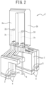
- Each combustion chamber 2 has a plurality of sets (16 sets in this embodiment) of two flues 2a, 2b (see FIG. 2 ) in the oven-length direction as illustrated in FIG. 6 .
- the sets of the flues 2a, 2b are arranged at a predetermined pitch along the oven-length direction.
- the sets of the flues 2a, 2b extend in the vertical direction, and each have a hairpin structure in which the flues 2a, 2b are allowed to communicate with each other in top portions of the flues 2a, 2b as illustrated in FIGS. 2 and 6 .
- regenerators 3 are divided in the oven-length direction, and the predetermined regenerator 3 is allowed to communicate with one set of the flues 2a, 2b of each combustion chamber 2.
- a bottom section of each regenerator 3 aligned in the oven-length direction is allowed to communicate with a sole flue 4 extending in the oven-length direction, and a nozzle plate 5 with an opening section is interposed between each regenerator 3 and the sole flue 4.
- a route for supplying fuel gas (M gas: mixed gas of coke oven gas and blast furnace gas) and air and a route for discharging exhaust gas from the one set of the flues 2a, 2b are individually formed. More specifically, the M gas and air are individually poured from one end on a coke side (CS) of the sole flues 4 different from each other, enter the regenerator 3 via the nozzle plate 5, followed by preheating therein, and then introduced into either one of one set of the flues 2a, 2b for combustion.
- M gas mixed gas of coke oven gas and blast furnace gas
- Exhaust gas of the combustion is drawn down from the other one of the one set of the flues 2a, 2b to the regenerator 3, followed by heat recovery therein, enters the sole flue 4, and then exhausted from the other end on a pusher side (PS).
- the supply route of the M gas and air and the exhaust route of the exhaust gas are switched every predetermined time interval, and the preheating and the heat recovery are alternately performed in the regenerator 3.
- two-stage combustion is performed.
- air is supplied from the bottom sections of the flues 2a, 2b, and, in a second stage, an air supply path 2c is formed in a partition wall between the flues 2a, 2b and air is supplied from the supply path 2c to the flue 2a or 2b as illustrated in FIGS. 2 and 3 .
- the predetermined regenerator 3 is allowed to communicate with one supply path 2c, and air sent to this regenerator 3 is blown off to the flue 2a or 2b via the supply path 2c in the partition wall.
- bricks constituting the combustion chamber 2 are prone to deterioration particularly in a section close to a coke oven port, and therefore the formation of the supply path 2c is desired to be prevented only in the partition wall partitioning the outside of the oven positioned at the endmost in the oven-length direction. Therefore, as illustrated in FIG.
- a blowoff port 2d of the supply path 2c formed in the partition wall between the flue 2a or 2b positioned at the endmost in the oven-length direction and the flue 2b or 2a adjacent to the flue 2a or 2b positioned at the endmost is formed towards the side of the flue 2a or 2b positioned at the endmost, i.e., towards the side of the coke oven port, and all of the subsequent blowoff ports 2d are also directed towards the side of the coke oven port.
- the blowoff ports 2d are formed back-to-back on the coke side (CS) and the pusher side (PS) with the center in the oven-length direction as the boundary.
- both the supply path 2c performing blowing-off to the coke side and the supply path 2c performing blowing-off to the pusher side are provided.
- the combustion temperatures of the flues 2a, 2b depend on the flow rates of the M gas and the air supplied thereto, and therefore the combustion temperatures are regulated by regulating the flow rate of the fuel gas passing through the nozzle plate 5 by regulating the opening area of the nozzle plate 5.
- a vertical pipe 6 supplying fuel gas (C Gas: coke oven gas) is allowed to communicate with the bottom section of each of the flues 2a, 2b.
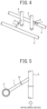
- Each vertical pipe 6 is allowed to communicate with a distribution pipe 8 via a branch pipe 7, and a chip 9 capable of controlling the flow rate is provided in the middle of the branch pipe 7 as illustrated in FIG. 4 .
- the C gas poured into the distribution pipe 8 does not pass through the regenerator 3, and is supplied directly to one of the flues 2a and 2b through the branch pipe 7 and the vertical pipe 6, so that combustion occurs in one of the flues 2a and 2b.
- Exhaust gas of the combustion is the same as that in the combustion of the M gas described above.
- the coke oven A includes the M gas supply system and the C gas supply system (distribution pipe 8, branch pipe 7, and vertical pipe 6) capable of supplying the M gas and the C gas to each of the flues 2a, 2b of the combustion chamber 2 and the air supply system (including the supply path 2c) capable of supplying air to each of the flues 2a, 2b of the combustion chamber 2, and involves M gas combustion performed by the M gas and the air and C gas combustion performed by the C gas and the air.
- the coke oven A is operated by either one of the M gas combustion and the C gas combustion. However, the coke oven A is operated mainly by the M gas combustion.
- the C gas supply system When the coke oven A is operated by the M gas combustion, the C gas supply system is not used and is in a resting state, and therefore, to supply air in an appropriate supply amount to one or two or more of the flues 2a, 2b with the reduced combustion temperature among the plurality (32 sets in this embodiment) of flues 2a, 2b of the combustion chamber 2 by diverting the C gas supply system, an air blowing device 20 is connected to the vertical pipe 6 of the C gas supply system allowed to communicate with the plurality (32 sets in this embodiment) of flues 2a, 2b in the combustion chamber 2 as illustrated in FIG. 6 . At this time, as illustrated in FIG.
- the chip 9 of the branch pipe 7 allowed to communicate with each of the flues 2a, 2b is replaced with a blind chip 10.
- the branch pipe 7 is disconnected (separated) from the distribution pipe 8.
- the air blowing device 20 is connected to the lower end of the vertical pipe 6 disconnected from the distribution pipe 8, enabling the air supply.
- the reference numeral 11 denotes an air inlet
- the reference numeral 12 denotes an M gas supply pipe
- the reference numeral 13 denotes an exhaust port.
- the air blowing device 20 supplies air in an amount corresponding to the air flow rate shortage to the flues 2a, 2b having the air flow rate shortage larger than the predetermined threshold ⁇ , and includes a plurality (32 in this embodiment) of air blowing sections 20b supplying air to each of the flues 2a, 2b and an air-blowing control section 20a controlling the air blowing of the plurality of air blowing sections 20b as illustrated in FIG. 7 .
- the "predetermined threshold ⁇ " is set based on the air ratio. For example, when the air ratio is 0.8 or less, air in an amount corresponding to the air flow rate shortage is blown.
- the dry distillation heat quantity is set to 600 Mcal/t
- the coal supply amount per one time to one combustion chamber is set to 30 t
- the theoretical air amount (volume ratio) required for the complete combustion of the M gas is set to 1
- the heat quantity of the M gas is set to 1.200 [Mcal/Nm 3 ]
- the air ratio of the design value of the coke oven is set to 1.2
- a time required for one dry distillation is set to 17.5 hours
- Air-ratio blowing gas amount Air blowing amount into one flue ⁇ (Air ratio of design value - Actual air ratio)/ Air ratio of design value ⁇ 38.5 Nm 3 /h is blown into the flues 2a, 2b determined to have a low air ratio (flues 2a, 2b determined to have the air flow rate shortage larger than the predetermined threshold ⁇ ).
- Each air blowing section 20b is connected to a common air pipe connected to an air supply source, and is configured to supply air in an amount corresponding to the air flow rate according to the opening degree of a valve provided in each air blowing section 20b to each of the flues 2a, 2b.
- the air-blowing control section 20a is a computer system with an arithmetic processing function, and is configured to determine whether there are the flues 2a, 2b having the air flow rate shortage calculated by the air supply amount calculation device 21 larger than the predetermined threshold ⁇ , and, when there are the flues 2a, 2b having the air flow rate shortage larger than the predetermined threshold ⁇ , control the valve opening degree of the air blowing sections 20b supplying air to the flues 2a, 2b having the air flow rate shortage larger than the predetermined threshold ⁇ , and supply air in an amount corresponding to the air flow rate shortage to the flues 2a, 2b.
- the air supply amount calculation device 21 is connected, the air supply amount calculation device 21 calculating the air flow rate shortage for each of the flues 2a, 2b based on the measured temperature in each of the flues 2a, 2b in the combustion chamber 2.
- the air supply amount calculation device 21 includes an operation data acquisition section 21a, a first distribution flow rate estimation section 21b, a flue internal temperature acquisition section 21c, a second distribution flow rate estimation section 21d, an air flow rate shortage calculation section 21e, and an output section 21f as illustrated in FIG. 8 .
- the air supply amount calculation device 21 is a computer system with an arithmetic processing function, and is configured to execute various dedicated computer programs stored in advance in hardware, thereby enabling the realization, on software, of the functions of the operation data acquisition section 21a, the first distribution flow rate estimation section 21b, the flue internal temperature acquisition section 21c, the second distribution flow rate estimation section 21d, the air flow rate shortage calculation section 21e, and the output section 21f.
- the operation data acquisition section 21a acquires operation data stored in an operation result database 22 (see FIG. 6 )).
- the operation result database 22 stores the operation data when coke oven operation was performed in the past.
- the operation data is result data in the coke oven operation, such as the total flow rate of the fuel gas supplied to the combustion chamber 2, the valve opening degree for supplying the fuel gas to each of the flues 2a, 2b, and a top pressure.
- the first distribution flow rate estimation section 21b estimates the distribution flow rate of each of the fuel and the air to each of the flues 2a, 2b in the combustion chamber 2 based on the operation data acquired by the operation data acquisition section 21a. Specifically, the first distribution flow rate estimation section 21b estimates the distribution flow rate of each of the fuel and the air to each of the flues 2a, 2b from the total flow rate of the fuel gas supplied to the combustion chamber 2, the valve opening degree for supplying the fuel gas to each of the flues 2a, 2b, and the top pressure of the operation data acquired by the operation data acquisition section 21a.
- the flue internal temperature acquisition section 21c acquires a calculation value of temperature in each of the flues 2a, 2b from the distribution flow rate of each of the fuel and the air to each of the flues 2a, 2b in the combustion chamber 2 estimated by the first distribution rate estimation section 21b and the relationship between temperature data in each of the flues 2a, 2b and the distribution flow rate of each of the fuel and the air in each of the flues 2a, 2b in the combustion chamber 2 stored in a fuel/air flow rate database 23.
- the fuel/air flow rate database 23 stores the relationship between the temperature data in each of the flues 2a, 2b and the distribution flow rate of each of the fuel and the air in each of flues 2a, 2b in the combustion chamber 2 obtained by carrying out a large number of combustion simulations according to the fuel amount, the air amount, the operation rate, and the like.
- the second distribution flow rate estimation section 21d estimates the actual distribution flow rate of each of the fuel and the air in each of the flues 2a, 2b from temperature data in each of the flues 2a, 2b obtained by the measurement in each of the flues 2a, 2b in the combustion chamber 2 and the relationship between the temperature data in each of the flues 2a, 2b and the distribution flow rate of each of the fuel and the air in each of the flues 2a, 2b stored in the fuel/air flow rate database 23.
- the measured temperature data in each of the flues 2a, 2b is specifically data of a temperature distribution of the oven bottom of each of the flues 2a, 2b in the combustion chamber 2.
- the air flow rate shortage calculation section 21e calculates the air flow rate shortage for each of the flues 2a, 2b in the combustion chamber 2 relative to the air ratio of the design value from the distribution flow rate of each of the fuel and the air to each of the flues 2a, 2b in the combustion chamber 2 estimated by the first distribution flow rate estimation section 21b and the actual distribution flow rate of each of the fuel and the air in each of the flues 2a, 2b estimated by the second distribution flow rate estimation section 21d.
- the air ratio of the design value is specifically set to about 1.2.
- the output section 21f outputs, to the air blowing device 20, the results of the calculation by the air flow rate shortage calculation section 21e, i.e., data of the air flow rate shortage for each of the flues 2a, 2b in the combustion chamber 2 calculated by the air flow rate shortage calculation section 21e.
- the air blowing device 20 supplies air in an amount corresponding to the air flow rate shortage to the flues 2a, 2b having the large air flow rate shortage.
- the coke oven A in this embodiment includes the air blowing device 20 connected, in an operation with one fuel supply system (M gas supply system) and the air supply system (including the supply path 2c) in the combustion chamber 2, to the other fuel supply system (C gas supply system) to supply air to each of the flues, 2a 2b by diverting the other fuel supply system (C gas supply system), and the air supply amount calculation device 21 calculating the air flow rate shortage for each of the flues 2a, 2b based on the measured temperature in each of the flues 2a, 2b in the combustion chamber 2.
- M gas supply system fuel supply system
- C gas supply system the other fuel supply system
- the air blowing device 20 supplies air in an amount corresponding to the air flow rate shortage to the flues 2a, 2b having the air flow rate shortage larger than the predetermined threshold ⁇ .
- the supply of air in an amount corresponding to the air flow rate shortage to the flues 2a, 2b with a reduced combustion temperature in the combustion chamber 2 increases the internal temperature of the flues 2a, 2b, uniformizing the temperature distribution in the oven-length direction in the combustion chamber 2, and the supply of air in an appropriate supply amount to the flues 2a, 2b with a reduced combustion temperature in the combustion chamber 2 enables the regulation of the temperature distribution in the oven-length direction in the combustion chamber 2.
- the air supply amount calculation device 21 includes the operation data acquisition section 21a acquiring the operation data of the combustion chamber 2 stored in the operation result database 22, and the first distribution flow rate estimation section 21b estimating the distribution flow rate of each of the fuel and the air to each of the flues 2a, 2b based on the operation data acquired by the operation data acquisition section 21a.
- the coke oven A in this embodiment includes the second distribution flow rate estimation section 21d estimating the actual distribution flow rate of each of the fuel and the air in each of the flues 2a, 2b from the temperature data in each of the flues 2a, 2b obtained by the measurement in each of the flues 2a, 2b and the relationship between the temperature data in each of the flues 2a, 2b and the distribution flow rate of each of the fuel and the air in each of the flues 2a, 2b stored in the fuel/air flow rate database 23, and the air flow rate shortage calculation section 21e calculating the air flow rate shortage for each of the flues 2a, 2b relative to the air ratio of the design value from the distribution flow rate of each of the fuel and the air to each of the flues 2a, 2b estimated by the first distribution flow rate estimation section 21b and the actual distribution flow rate of each of the fuel and the air in each of the flues 2a, 2b estimated by the second distribution flow rate estimation section 21d.
- the design is such that, in the combustion chambers 2 adjacent to each other in the longitudinal direction of coke oven battery, odd and even numbers of the gas blowing flues 2a, 2b and the exhausting flues 2a, 2b are different from each other, and the gas blowing flues 2a, 2b and the exhausting flues 2a, 2b alternate every predetermined time interval.
- the air blowing device 20, solenoid valves M1, M2, ..., M32, M33, and pipes P1, P2, ..., P32, P33 are preferably designed as follows as illustrated in FIG. 15 .
- flues N1 in the combustion chambers i, iii v along the longitudinal direction of coke oven battery are connected to the air blowing device 20 by a pipe P1 in which a solenoid valve M1 is installed.
- the flues N1 of the combustion chambers ii, iv are connected to the air blowing device 20 by a pipe P2 in which a solenoid valve M2 is installed.
- Flues N2 of the combustion chambers i, iii, v along the longitudinal direction of coke oven battery are connected to the air blowing device 20 by the pipe P2 in which the solenoid valve M2 is installed.
- the flues N2 of the combustion chambers ii, iv are connected to the air blowing device 20 by a pipe P3 in which a solenoid valve M3 is installed.
- flues N32 of the combustion chambers i, iii, v along the longitudinal direction of coke oven battery are connected to the air blowing device 20 by a pipe P32 in which a solenoid valve M32 is installed.
- the flues N32 of the combustion chambers ii, iv are connected to the air blowing device 20 by a pipe P33 in which a solenoid valve M33 is installed.
- the solenoid valves marked with an X mark in FIG. 15 may be manual valves or automatic valves.
- FIG. 15 illustrates the five combustion chambers i to v along the longitudinal direction of coke oven battery, and the description thereof is given above, but the number of the combustion chambers along the longitudinal direction of coke oven battery is not limited to five.
- FIG. 9 illustrates the process flow in regulating the temperature distribution in the oven-length direction of the combustion chamber 2.
- the air supply amount calculation device 21 calculates the air flow rate shortage for each of the flues 2a, 2b based on the measured temperature in each of the flues 2a, 2b in the combustion chamber 2 (air supply amount calculation step) .
- the operation data acquisition section 21a of the air supply amount calculation device 21 acquires the operation data stored in the operation result database 22 (operation data acquisition step).
- the operation data is the result data in the coke oven operation, such as the total flow rate of the fuel gas supplied to the combustion chamber 2, the valve opening degree for supplying the fuel gas to each of the flues 2a, 2b, and the top pressure.
- the first distribution flow rate estimation section 21b of the air supply amount calculation device 21 estimates the distribution flow rate of each of the fuel and the air to each of the flues 2a, 2b in the combustion chamber 2 based on the operation data acquired in Step S11 (operation data acquisition step) (first distribution flow rate estimation step). Specifically, the first distribution flow rate estimation section 21b estimates the distribution flow rate of each of the fuel and the air to each of the flues 2a, 2b from the total flow rate of the fuel gas supplied to the combustion chamber 2, the valve opening degree for supplying the fuel gas to each of the flues 2a, 2b, and the top pressure of the operation data acquired in Step S11 (operation data acquisition step).
- the flue internal temperature acquisition section 21c of the air supply amount calculation device 21 acquires a calculation value of the temperature in each of the flues 2a, 2b from the distribution flow rate of each of the fuel and the air to each of the flues 2a, 2b in the combustion chamber 2 estimated in Step S12 (first distribution rate estimation step) and the relationship between the temperature data in each of the flues 2a, 2b and the distribution flow rate of each of the fuel and the air in each of the flues 2a, 2b in the combustion chamber 2 stored in the fuel/air flow rate database 23 (temperature calculation value acquisition step).
- the fuel/air flow rate database 23 stores the relationship between the temperature data in each of the flues 2a, 2b and the distribution flow rate of each of the fuel and the air in each of flues 2a, 2b in the combustion chamber 2 obtained by carrying out a large number of combustion simulations according to the fuel amount, the air amount, the operation rate, and the like.
- the second distribution flow rate estimation section 21d of the air supply amount calculation device 21 estimates the actual distribution flow rate of each of the fuel and the air in each of the flues 2a, 2b from the temperature data in each of the flues 2a, 2b obtained by the measurement in each of the flues 2a, 2b in the combustion chamber 2 and the relationship between the temperature data in each of the flues 2a, 2b and the distribution flow rate of each of the fuel and the air in each of the flues 2a, 2b stored in the fuel/air flow rate database 23 (second distribution rate estimation step).
- the measured temperature data in each of the flues 2a, 2b is specifically data of a temperature distribution of the oven bottom of each of the flues 2a, 2b in the combustion chamber 2.
- the air flow rate shortage calculation section 21e of the air supply amount calculation device 21 calculates the air flow rate shortage for each of the flues 2a, 2b in the combustion chamber 2 relative to the air ratio of the design value from the distribution flow rate of each of the fuel and the air to each of the flues 2a, 2b in the combustion chamber 2 estimated in Step S12 (first distribution flow rate estimation step) and the actual distribution flow rate of each of the fuel and the air in each of the flues 2a, 2b estimated in Step S14 (second distribution flow rate estimation step) (air flow rate shortage calculation step).
- the air ratio of the design value is specifically set to about 1.2.
- Step S16 the output section 21f of the air supply amount calculation device 21 outputs, to the air blowing device 20, the data of the air flow rate shortage for each of the flues 2a, 2b in the combustion chamber 2 calculated in Step S15 (air flow rate shortage calculation step).
- Step S1 air supply amount calculation step
- air in an amount corresponding to the air flow rate shortage is supplied from the air blowing device 20 to the flues 2a, 2b having the air flow rate shortage larger than the predetermined threshold ⁇ , regulating the temperature distribution in the oven-length direction of the combustion chamber 2 in Step S2 as illustrated in FIG. 9 (air blowing step).
- Step S21 the air-blowing control section 20a of the air blowing device 20 acquires the data of the air flow rate shortage for each of the flues 2a, 2b in the combustion chamber 2 calculated in Step S1 (air supply amount calculation step).
- Step S22 the air-blowing control section 20a of the air blowing device 20 determines whether there are the flues 2a, 2b having the air flow rate shortage for each of the flues 2a, 2b in the combustion chamber 2 larger than the predetermined threshold ⁇ (determination step) .
- the "predetermined threshold ⁇ " is set based on the air ratio. For example, when the air ratio is 0.8 or less, air in an amount corresponding to the shortage is blown.
- the dry distillation heat quantity is set to 600 Mcal/t
- the coal supply amount per one time to one combustion chamber is set to 30 t
- the theoretical air amount (volume ratio) required for the complete combustion of the M gas is set to 1
- the heat quantity of the M gas is set to 1.200 [Mcal/Nm 3 ]
- the air ratio of the design value of the coke oven is set to 1.2
- a time required for one dry distillation is set to 17.5 hours
- Air-ratio blowing gas amount Air blowing amount into one flue ⁇ (Air ratio of design value - Actual air ratio)/ Air ratio of design value ⁇ 38.5 Nm 3 /h is blown into the flues 2a, 2b determined to have a low air ratio (flues 2a, 2b determined to have the air flow rate shortage larger than the predetermined threshold ⁇ ).
- Step S22 determination step
- Step S23 determination step
- Step S23 the air-blowing control section 20a of the air blowing device 20 issues a command to supply air in an amount corresponding to the air flow rate shortage to the air blowing section 20b supplying air to the flues 2a, 2b having the air flow rate shortage larger than the predetermined threshold ⁇ .
- the air blowing section 20b supplies air in an amount corresponding to the air flow rate shortage to the flues 2a, 2b having the air flow rate shortage larger than the predetermined threshold ⁇ according to the command, and regulates the temperature distribution in the oven-length direction of the combustion chamber 2 (air supply step).
- the method for regulating the temperature distribution in the coke oven in this embodiment includes the air supply amount calculation step (Step S1) of calculating the air flow rate shortage for each of the flues 2a, 2b based on the measured temperature in the flues 2a, 2b in the combustion chamber 2 by the air supply amount calculation device 21, and the air blowing step (Step S2) of, when there are the flues 2a, 2b having the air flow rate shortage calculated in the air supply amount calculation step larger than the predetermined threshold ⁇ , supplying air in an amount corresponding to the air flow rate shortage to the flues 2a, 2b having the air flow rate shortage larger than the predetermined threshold ⁇ from the air blowing device 20 connected, in the operation with the one fuel supply system (M gas supply system) of the fuel supply systems and the air supply system in the combustion chamber 2, to the other fuel supply system (C gas supply system) to supply air to each of the flues, 2a 2b by diverting the other fuel supply system (C gas supply system), regulating the temperature distribution in the oven
- the supply of air in an amount corresponding to the air flow rate shortage to the flues 2a, 2b with a reduced combustion temperature in the combustion chamber 2 increases the internal temperature of the flues 2a, 2b, uniformizing the temperature distribution in the oven-length direction in the combustion chamber 2, and the supply of air in an appropriate supply amount to the flues 2a, 2b with a reduced combustion temperature in the combustion chamber 2 enables the regulation of the temperature distribution in the oven-length direction in the combustion chamber 2.
- the air supply amount calculation step (Step S1) includes the operation data acquisition step (Step S11) of acquiring the operation data of the combustion chamber 2 stored in the operation result database 22, and the first distribution flow rate estimation step (Step S12) of estimating the distribution flow rate of each of the fuel and the air to each of the flues 2a, 2b based on the operation data acquired in the operation data acquisition step (Step S11).
- the air supply amount calculation step (Step S1) includes the second distribution flow rate estimation step (Step S14) of estimating the actual distribution flow rate of each of the fuel and the air in each of the flues 2a, 2b from the temperature data in each of the flues 2a, 2b obtained by the measurement in each of the flues 2a, 2b and the relationship between the temperature data in each of the flues 2a, 2b and the distribution flow rate of each of the fuel and the air in each of the flues 2a, 2b stored in the fuel/air flow rate database 23, and the air flow rate shortage calculation step (Step S15) of calculating the air flow rate shortage for each of the flues 2a, 2b relative to the air ratio of the design value from the distribution flow rate of each of the fuel and the air to each of the flues 2a, 2b estimated in the first distribution flow rate estimation step (Step S12) and the actual distribution flow rate of each of the fuel and the air in each of the flues 2a, 2b estimated in the second distribution
- the coke oven A is operated by regulating the temperature distribution in the oven-length direction of the combustion chamber 2 by the method for regulating the temperature distribution in the coke oven.
- Coke is produced by operating the coke oven A as described above.
- the supply of air in an amount corresponding to the air flow rate shortage to the flues 2a, 2b in the combustion chamber 2 with a reduced combustion temperature increases the internal temperature of such flues 2a, 2b, uniformizing the temperature distribution in the oven-length direction in the combustion chamber 2, and thus the temperature regulation in the oven-length direction in the combustion chamber 2 is achieved and excellent coke can be produced.
- the air blowing device 20 regulates the temperature distribution in the oven-length direction of the combustion chamber 2 by supplying, when there are the flues 2a, 2b having the air flow rate shortage calculated by the air supply amount calculation device 21 (air supply amount calculation step: Step S1) larger than the predetermined threshold ⁇ , air in an amount corresponding to the air flow rate shortage to the flues 2a, 2b having the air flow rate shortage larger than the predetermined threshold ⁇ from the air blowing device 20.
- the air blowing device 20 may omit the determination (determination step: Step S22) by the air-blowing control section 20a whether there are the flues 2a, 2b having the air flow rate shortage larger than the predetermined threshold ⁇ for each of the flues 2a, 2b in the combustion chamber 2, and may regulate the temperature distribution in the oven-length direction of the combustion chamber 2 by supplying air in an amount corresponding to the air flow rate shortage calculated by the air supply amount calculation device 21 (air supply amount calculation step: Step S1) to the flues 2a, 2b which are short of the air flow rate, irrespective of the threshold value ⁇ .
- the supply of air in an amount corresponding to the air flow rate shortage to the flues 2a, 2b with a reduced combustion temperature in the combustion chamber 2 increases the internal temperature of the flues 2a, 2b, uniformizing the temperature distribution in the oven-length direction in the combustion chamber 2, and the supply of air in an appropriate supply amount to the flues 2a, 2b with a reduced combustion temperature in the combustion chamber 2 enables the regulation of the temperature distribution in the oven-length direction in the combustion chamber 2.
- the 16 sets of the 32 flues 2a, 2b are provided in the combustion chamber 2, two or more of the sets of the two flues 2a, 2b may be provided, and the number is not limited to the 16 sets of the 32 flues 2a, 2b.
- the air blowing device 20 is connected to the vertical pipes 6 of the C gas supply system allowed to communicate with all of the 16 sets of 32 flues 2a, 2b in the combustion chamber 2 but are not necessarily connected to the vertical pipes 6 of the C gas supply system allowed to communicate with all of the 16 sets of 32 flues 2a, 2b in the combustion chamber 2 and may be connected to the vertical pipes 6 of the C gas supply system allowed to communicate with the flues 2a, 2b in the number equal to or less than 15 sets of 30 flues 2a, 2b in the combustion chamber 2.
- the air supply amount calculation device 21 and the air blowing device 20 are connected, but a configuration may be acceptable in which the air supply amount calculation device 21 and the air blowing device 20 are disconnected, the calculation results of the air supply amount calculation device 21 are displayed on a display device (not illustrated), a worker enters the calculation results displayed on the display device into the air blowing device 20, and air in an amount corresponding to the air flow rate shortage is blown into the flues 2a, 2b having the air flow rate shortage larger than the predetermined threshold ⁇ or air in an amount corresponding to the air flow rate shortage is supplied to the flues 2a, 2b which are short of the air flow rate.
- the supply amount calculation section 21 includes the flue internal temperature acquisition section 21c, the flue internal temperature acquisition section 21c may be omitted and Step S13 (temperature calculation value acquisition step) may be omitted.
- air in an amount corresponding to the air flow rate shortage was supplied to the flues 2a, 2b in the center in the oven-length direction where a temperature reduction was noticeable in the combustion chamber 2 as in the temperature distribution in FIG. 12 from the vertical pipes 6 of the C gas supply system in the operation with the M gas combustion.
- the air flow rate shortage was calculated by the air supply amount calculation device 21 according to the air supply amount calculation step illustrated in FIG. 10 , and air in an amount corresponding to the calculated air flow rate shortage was blown from the air blowing device 20.
- FIG. 13 illustrates the relationship between the oven wall temperature estimated from the measured temperature in the flues 2a, 2b in the center in the oven-length direction in the combustion chamber 2 having the temperature distribution illustrated in FIG. 12 and the oven wall temperature estimated from the temperature of the calculation value in the flues 2a, 2b in the center in the oven-length direction (oven wall temperature estimated from the temperature of the calculation value in the flues 2a, 2b in the center in the oven-length direction acquired in Step S13).
- the oven wall temperature estimated from the measured temperature is about 50°C lower than the oven wall temperature estimated from the temperature of the calculation value.
- the air flow rate shortage for each of the flues 2a, 2b was calculated relative to the air ratio of the design value (1.2) in Step S15.
- the results were such that the flues 2a, 2b in the center in the oven-length direction had the air flow rate shortage relative to the air ratio of 1.2 was 40 Nm 3 /h for and the air ratio of 0.7.
- the air ratio of 0.7 was lower than the predetermined threshold (air ratio of 0.8), and therefore air in an amount corresponding to the air flow rate shortage of 40 Nm 3 /h was blown from the air blowing device 20 to the flues 2a, 2b in the center in the oven-length direction via the vertical pipe 6 of the C gas supply system in combustion.
Landscapes
- Chemical & Material Sciences (AREA)
- Engineering & Computer Science (AREA)
- Combustion & Propulsion (AREA)
- Materials Engineering (AREA)
- Oil, Petroleum & Natural Gas (AREA)
- Organic Chemistry (AREA)
- Mechanical Engineering (AREA)
- General Engineering & Computer Science (AREA)
- Coke Industry (AREA)
Abstract
Description
- The present invention relates to a coke oven, a method for regulating a temperature distribution in the coke oven, a method for operating the coke oven, and a method for producing coke.
- One of technologies of improving the combustion of a coke oven is a multi-stage combustion technology of lowering the flame temperature and reducing NOx, which is a technology of supplying about 80 to 90% of air required for complete combustion in a lower part of a combustion chamber and supplying air in an amount corresponding to a shortage in an upper part of the combustion chamber, thereby achieving complete combustion as a whole (see PTL 1) .
- As a structure of supplying air to the upper part for multi-stage combustion, a structure is mentioned in which an air supply path is formed in a partition wall between combustion chambers subdivided in the oven-length direction, and air is supplied to the combustion chambers on one side from the supply path. However, bricks constituting the combustion chambers are prone to deterioration particularly in a part close to a coke oven port, and therefore the formation of the above-described supply path is desired to be prevented only in a partition wall partitioning the outside of the oven positioned at the endmost in the oven-length direction. Therefore, a blowoff port of the supply path formed in the partition wall between the combustion chamber positioned at the endmost in the oven-length direction and the combustion chamber adjacent thereto needs to be formed towards the side of the combustion chamber positioned at the endmost, i.e., towards the side of the coke oven port, and the subsequent blowoff ports are also necessarily directed towards the side of the coke oven port. Therefore, the blowoff ports are formed back-to-back on a coke side (CS) and a pusher side (PS) with the center in the oven-length direction as the boundary. Only in the partition wall positioned in the center in the oven-length direction, both the supply path of blowing off air to the coke side and the supply path blowing off air to the pusher side are provided.
- The two supply paths provided in the center partition wall have a cross-sectional area smaller than that of the supply paths formed in the other partition walls to prevent deterioration of the strength of the partition wall. This has posed such a problem that the ventilation resistance of the two supply paths is large, so that pressure loss becomes correspondingly large, resulting in a reduction in the flow rate of air that can be supplied and a reduction in the combustion temperature, which lowering the combustion temperature of the center in the oven-length direction.
- To solve this problem,
PTL 2 describes a method for regulating a temperature distribution in a coke oven having two fuel supply systems capable of supplying fuel gas to each of combustion chambers subdivided in the oven-length direction and an air supply system capable of supplying air to each of the combustion chambers, in which, in an operation with one fuel supply system of the fuel supply systems and the air supply system, air is supplied by diverting the other fuel supply system to a predetermined combustion chamber positioned in the center in the oven-length direction, thereby regulating the temperature distribution in the oven-length direction of the combustion chamber. -
- PTL 1:
JP 2001-81470 A - PTL 2:
JP 2009-46536 A - The bricks constituting the combustion chambers of the coke oven are deteriorated as described above, but this deterioration results in a decrease only in air ratios of the flues in the vicinity of the deteriorated bricks in some cases. More specifically, mortar applied between the brick and the brick is broken, so that volatile gas generated during dry distillation of coal flows from a carbonization chamber to the flue of the combustion chamber, causing the reduction in the air ratio and the reduction in the combustion temperature in some cases.
- The reduction in the air ratio needs to be eliminated, because the reduction in the air ratio causes problems, such as the generation of dust of soot generated due to a reduction in the combustion efficiency caused by unburned fuel or pyrolysis and blockage of a gas flow path.
- In this case, air is supplied to the flues positioned in the center in the oven-length direction according to the method for regulating the temperature distribution in the coke oven described in
PTL 2, but the flues having the reduced combustion temperature and the reduced air ratio is not limited to the flues positioned in the center in the oven-length direction, and therefore air cannot be always supplied to the flues requiring the air supply. Further, the method for regulating the temperature distribution in the coke oven inPTL 2 does not describe the air supply amount to the flues, and therefore there is a risk that air in an excessive supply amount is blow into the flues positioned in the center in the oven-length direction, deteriorating the temperature distribution in the oven-length direction in the combustion chamber. - It is conceivable that air is blown uniformly to all of the flues in the entire combustion chamber to increase the air ratio of the flues having the reduced air ratio. However, this case results in a loss of energy because air is blown even to the flues not requiring the air supply.
- Thus, the present invention has been made to solve the conventional problem. It is an object of the present invention to provide a coke oven, a method for regulating the temperature distribution in the coke oven, a method for operating the coke oven, and a method for producing coke, which can regulate the temperature distribution in the oven-length direction in a combustion chamber by supplying air in an appropriate supply amount to the flues with a reduced combustion temperature of the combustion chamber.
- To achieve the above-described object, a coke oven according to one aspect of the present invention is a coke oven with a combustion chamber having a plurality of sets of two flues, two fuel supply systems capable of supplying fuel gas to each of the flues of the combustion chamber, and an air supply system capable of supplying air to each of the flues of the combustion chamber in the oven-length direction, including: an air blowing device connected, in an operation with one fuel supply system of the two fuel supply systems and the air supply system in the combustion chamber, to the other fuel supply system to supply air to each of the flues by diverting the other fuel supply system; and an air supply amount calculation device configured to calculate the air flow rate shortage for each of the flues based on the measured temperature in each of the flues in the combustion chamber, in which the air blowing device supplies air in an amount corresponding to the air flow rate shortage calculated by the air supply amount calculation device to the flues having the air flow rate shortage.
- A method for regulating a temperature distribution in a coke oven according to another aspect of the present invention is a method for regulating the temperature distribution in a coke oven with a combustion chamber having a plurality of sets of two flues, two fuel supply systems capable of supplying fuel gas to each of the flues of the combustion chamber, and an air supply system capable of supplying air to each of the flues of the combustion chamber in the oven-length direction, including: an air supply amount calculation step of calculating the air flow rate shortage for each of the flues based on the measured temperature in each of the flues in the combustion chamber by the air supply amount calculation device; and an air blowing step of supplying air in an amount corresponding to the air flow rate shortage calculated in the air supply amount calculation step to the flues having the air flow rate shortage from an air blowing device connected, in an operation with one fuel supply system of the two fuel supply systems and the air supply system in the combustion chamber, to the other fuel supply system to supply air to each of the flues by diverting the other fuel supply system, regulating the temperature distribution in the oven-length direction of the combustion chamber.
- A method for operating a coke oven according to another aspect of the present invention includes operating the coke oven by regulating the temperature distribution in the oven-length direction of the combustion chamber by the method for regulating the temperature distribution in the coke oven described above.
- A method for producing coke according to another aspect of the present invention includes producing coke by operating the coke oven according to the method for operating the coke oven described above.
- The coke oven, the method for regulating the temperature distribution in the coke oven, the method for operating the coke oven, and the method for producing coke can provide a coke oven, a method for regulating the temperature distribution in the coke oven, a method for operating the coke oven, and a method for producing coke, which can regulate the temperature distribution in the oven-length direction in the combustion chamber by supplying air in an appropriate supply amount to the flues with a reduced combustion temperature of the combustion chamber.
-
-
FIGS. 1A and 1B illustrate the outline configurations of a coke oven, in whichFIG. 1A is a cross-sectional view of the coke oven cut along the oven-length direction in a carbonization chamber andFIG. 1B is a cross-sectional view of the coke oven cut along the longitudinal direction of coke oven battery; -
FIG. 2 is a view for illustrating the configuration of sets of two flues and regenerators in a combustion chamber; -
FIG. 3 is a view for illustrating the outline configuration of air supply paths and blowoff ports; -
FIG. 4 is a view for illustrating the configuration of an existing C gas supply system; -
FIG. 5 is a view in which an air blowing device is connected to a vertical pipe of a C gas supply system to supply air to each of the flues by diverting the C gas supply system; -
FIG. 6 is a view for illustrating the outline configuration of a coke oven according to one embodiment of the present invention, butFIG. 6 does not illustrate the regenerators and the carbonization chambers; -
FIG. 7 is a view illustrating the outline configuration of an air blowing device in the coke oven illustrated inFIG. 6 ; -
FIG. 8 is a view illustrating the outline configuration of an air supply amount calculation device in the coke oven illustrated inFIG. 6 ; -
FIG. 9 is a flowchart for illustrating the processing flow for regulating a temperature distribution in the oven-length direction of the combustion chamber; -
FIG. 10 is a flowchart for illustrating a detailed process flow of Step S1 (air supply amount calculation step) in the flowchart illustrated inFIG. 9 ; -
FIG. 11 is a flowchart for illustrating a detailed process flow of Step S2 (air blowing step) in the flowchart illustrated inFIG. 9 ; -
FIG. 12 is a graph illustrating one example of a temperature distribution in the oven-length direction of the combustion chamber (the temperature of flues in the center in the oven-length direction decreases by about 50°C) ; -
FIG. 13 is a graph illustrating the relationship between the oven wall temperature estimated from the measured temperature in the flues in the center in the oven-length direction and the oven wall temperature estimated from the temperature of a calculation value in the flues in the center in the oven-length direction in the combustion chamber having the temperature distribution illustrated inFIG. 12 ; -
FIG. 14 is a graph for illustrating changes with time of the oven bottom temperature in the flues in the center in the oven-length direction, changes with time of the flow rate of air supplied to the flues in the center in the oven-length direction, and changes with time of the CO concentration in the flues in the center in the oven-length direction for illustrating the effect when air in an amount corresponding to the air flow rate shortage is supplied to the flues in the center in the oven-length direction in the combustion chamber having the temperature distribution illustrated inFIG. 12 ; and -
FIG. 15 is a view for illustrating a difference between odd and even numbers of gas blowing flues and exhausting flues in combustion chambers adjacent to each other in the longitudinal direction of coke oven battery. - Embodiments of the present invention will now be described with reference to the drawings. The embodiments described below exemplify devices or methods for embodying the technical idea of the present invention, and the technical idea of the present invention does not specify the materials, shapes, structures, arrangement, and the like of constituent components to the materials, shapes, structures, arrangement, and the like described below. The drawings are schematic. Therefore, it should be noted that the relationship between the thickness and the planar dimension, ratio, and the like are different from the actual relationship, ratio, and the like. The drawings include portions different in mutual dimensional relationships and ratios.
-
FIG. 1 illustrates the outline configuration of a coke oven. In a coke oven A illustrated inFIGS. 1A and 1B , a plurality ofcarbonization chambers 1 and a plurality ofcombustion chambers 2 are alternately arranged along the longitudinal direction of coke oven battery, and a plurality ofregenerators 3 is provided in the longitudinal direction of coke oven battery below thecarbonization chambers 1 and thecombustion chambers 2. Eachcombustion chamber 2 has a plurality of sets (16 sets in this embodiment) of twoflues FIG. 2 ) in the oven-length direction as illustrated inFIG. 6 . With respect to the plurality of sets of the twoflues flues flues flues flues FIGS. 2 and6 . - The
regenerators 3 are divided in the oven-length direction, and thepredetermined regenerator 3 is allowed to communicate with one set of theflues combustion chamber 2. A bottom section of eachregenerator 3 aligned in the oven-length direction is allowed to communicate with asole flue 4 extending in the oven-length direction, and anozzle plate 5 with an opening section is interposed between eachregenerator 3 and thesole flue 4. - For one set of the
flues flues sole flues 4 different from each other, enter theregenerator 3 via thenozzle plate 5, followed by preheating therein, and then introduced into either one of one set of theflues flues regenerator 3, followed by heat recovery therein, enters thesole flue 4, and then exhausted from the other end on a pusher side (PS). The supply route of the M gas and air and the exhaust route of the exhaust gas are switched every predetermined time interval, and the preheating and the heat recovery are alternately performed in theregenerator 3. - To lower the flame temperature and reduce NOx, two-stage combustion is performed. In a first stage, air is supplied from the bottom sections of the
flues air supply path 2c is formed in a partition wall between theflues supply path 2c to theflue FIGS. 2 and3 . More specifically, thepredetermined regenerator 3 is allowed to communicate with onesupply path 2c, and air sent to thisregenerator 3 is blown off to theflue supply path 2c in the partition wall. However, bricks constituting thecombustion chamber 2 are prone to deterioration particularly in a section close to a coke oven port, and therefore the formation of thesupply path 2c is desired to be prevented only in the partition wall partitioning the outside of the oven positioned at the endmost in the oven-length direction. Therefore, as illustrated inFIG. 3 , ablowoff port 2d of thesupply path 2c formed in the partition wall between theflue flue flue flue subsequent blowoff ports 2d are also directed towards the side of the coke oven port. Thus, theblowoff ports 2d are formed back-to-back on the coke side (CS) and the pusher side (PS) with the center in the oven-length direction as the boundary. Only in the partition wall positioned in the center in the oven-length direction, both thesupply path 2c performing blowing-off to the coke side and thesupply path 2c performing blowing-off to the pusher side are provided. The combustion temperatures of theflues nozzle plate 5 by regulating the opening area of thenozzle plate 5. - On the other hand, a
vertical pipe 6 supplying fuel gas (C Gas: coke oven gas) is allowed to communicate with the bottom section of each of theflues vertical pipe 6 is allowed to communicate with adistribution pipe 8 via abranch pipe 7, and achip 9 capable of controlling the flow rate is provided in the middle of thebranch pipe 7 as illustrated inFIG. 4 . The C gas poured into thedistribution pipe 8 does not pass through theregenerator 3, and is supplied directly to one of theflues branch pipe 7 and thevertical pipe 6, so that combustion occurs in one of theflues - As described above, the coke oven A includes the M gas supply system and the C gas supply system (
distribution pipe 8,branch pipe 7, and vertical pipe 6) capable of supplying the M gas and the C gas to each of theflues combustion chamber 2 and the air supply system (including thesupply path 2c) capable of supplying air to each of theflues combustion chamber 2, and involves M gas combustion performed by the M gas and the air and C gas combustion performed by the C gas and the air. The coke oven A is operated by either one of the M gas combustion and the C gas combustion. However, the coke oven A is operated mainly by the M gas combustion. - When the coke oven A is operated by the M gas combustion, the C gas supply system is not used and is in a resting state, and therefore, to supply air in an appropriate supply amount to one or two or more of the
flues flues combustion chamber 2 by diverting the C gas supply system, anair blowing device 20 is connected to thevertical pipe 6 of the C gas supply system allowed to communicate with the plurality (32 sets in this embodiment) offlues combustion chamber 2 as illustrated inFIG. 6 . At this time, as illustrated inFIG. 5 , thechip 9 of thebranch pipe 7 allowed to communicate with each of theflues blind chip 10. Thebranch pipe 7 is disconnected (separated) from thedistribution pipe 8. When a flow path can be completely closed by thechip 9, there is no need to replace thechip 9 with theblind chip 10. Then, theair blowing device 20 is connected to the lower end of thevertical pipe 6 disconnected from thedistribution pipe 8, enabling the air supply. InFIG. 6 , thereference numeral 11 denotes an air inlet, thereference numeral 12 denotes an M gas supply pipe, and thereference numeral 13 denotes an exhaust port. - When there are the
flues amount calculation device 21 described below larger than a predetermined threshold α, theair blowing device 20 supplies air in an amount corresponding to the air flow rate shortage to theflues air blowing sections 20b supplying air to each of theflues control section 20a controlling the air blowing of the plurality ofair blowing sections 20b as illustrated inFIG. 7 . - Herein, the "predetermined threshold α" is set based on the air ratio. For example, when the air ratio is 0.8 or less, air in an amount corresponding to the air flow rate shortage is blown. For example, when the dry distillation heat quantity is set to 600 Mcal/t, the coal supply amount per one time to one combustion chamber is set to 30 t, the theoretical air amount (volume ratio) required for the complete combustion of the M gas is set to 1, the heat quantity of the M gas is set to 1.200 [Mcal/Nm3], the air ratio of the design value of the coke oven is set to 1.2, a time required for one dry distillation is set to 17.5 hours, and the number of the flues on the fuel gas blowing side in one combustion chamber is set to 16 (= 32/2), the air amount per flue is 64 Nm3/h, because Air blowing amount into one flue = Dry distillation heat quantity × Coal supply amount per one time into one combustion chamber/Heat quantity of M gas × Theoretical heat quantity × Air ratio of design value of coke oven/Time required for one dry distillation/Number of flues on fuel gas blowing side in one combustion chamber is established.
- When there is the flue determined to have the air ratio of 0.75 in this example, air in an amount corresponding to Air-ratio blowing gas amount = Air blowing amount into one flue × (Air ratio of design value - Actual air ratio)/ Air ratio of design value ≈ 38.5 Nm3/h is blown into the
flues flues - Each
air blowing section 20b is connected to a common air pipe connected to an air supply source, and is configured to supply air in an amount corresponding to the air flow rate according to the opening degree of a valve provided in eachair blowing section 20b to each of theflues - The air-blowing
control section 20a is a computer system with an arithmetic processing function, and is configured to determine whether there are theflues amount calculation device 21 larger than the predetermined threshold α, and, when there are theflues air blowing sections 20b supplying air to theflues flues - To the
air blowing device 20, the air supplyamount calculation device 21 is connected, the air supplyamount calculation device 21 calculating the air flow rate shortage for each of theflues flues combustion chamber 2. - The air supply
amount calculation device 21 includes an operationdata acquisition section 21a, a first distribution flowrate estimation section 21b, a flue internaltemperature acquisition section 21c, a second distribution flowrate estimation section 21d, an air flow rateshortage calculation section 21e, and anoutput section 21f as illustrated inFIG. 8 . The air supplyamount calculation device 21 is a computer system with an arithmetic processing function, and is configured to execute various dedicated computer programs stored in advance in hardware, thereby enabling the realization, on software, of the functions of the operationdata acquisition section 21a, the first distribution flowrate estimation section 21b, the flue internaltemperature acquisition section 21c, the second distribution flowrate estimation section 21d, the air flow rateshortage calculation section 21e, and theoutput section 21f. - Herein, the operation
data acquisition section 21a acquires operation data stored in an operation result database 22 (seeFIG. 6 )). Theoperation result database 22 stores the operation data when coke oven operation was performed in the past. The operation data is result data in the coke oven operation, such as the total flow rate of the fuel gas supplied to thecombustion chamber 2, the valve opening degree for supplying the fuel gas to each of theflues - The first distribution flow
rate estimation section 21b estimates the distribution flow rate of each of the fuel and the air to each of theflues combustion chamber 2 based on the operation data acquired by the operationdata acquisition section 21a. Specifically, the first distribution flowrate estimation section 21b estimates the distribution flow rate of each of the fuel and the air to each of theflues combustion chamber 2, the valve opening degree for supplying the fuel gas to each of theflues data acquisition section 21a. - The flue internal
temperature acquisition section 21c acquires a calculation value of temperature in each of theflues flues combustion chamber 2 estimated by the first distributionrate estimation section 21b and the relationship between temperature data in each of theflues flues combustion chamber 2 stored in a fuel/airflow rate database 23. The fuel/airflow rate database 23 stores the relationship between the temperature data in each of theflues flues combustion chamber 2 obtained by carrying out a large number of combustion simulations according to the fuel amount, the air amount, the operation rate, and the like. - The second distribution flow
rate estimation section 21d estimates the actual distribution flow rate of each of the fuel and the air in each of theflues flues flues combustion chamber 2 and the relationship between the temperature data in each of theflues flues flow rate database 23. The measured temperature data in each of theflues flues combustion chamber 2. - The air flow rate
shortage calculation section 21e calculates the air flow rate shortage for each of theflues combustion chamber 2 relative to the air ratio of the design value from the distribution flow rate of each of the fuel and the air to each of theflues combustion chamber 2 estimated by the first distribution flowrate estimation section 21b and the actual distribution flow rate of each of the fuel and the air in each of theflues rate estimation section 21d. Herein, the air ratio of the design value is specifically set to about 1.2. - Further, the
output section 21f outputs, to theair blowing device 20, the results of the calculation by the air flow rateshortage calculation section 21e, i.e., data of the air flow rate shortage for each of theflues combustion chamber 2 calculated by the air flow rateshortage calculation section 21e. - When there are the
flues amount calculation device 21 larger than the predetermined threshold α as described above, theair blowing device 20 supplies air in an amount corresponding to the air flow rate shortage to theflues - As described above, the coke oven A in this embodiment includes the
air blowing device 20 connected, in an operation with one fuel supply system (M gas supply system) and the air supply system (including thesupply path 2c) in thecombustion chamber 2, to the other fuel supply system (C gas supply system) to supply air to each of the flues,2a 2b by diverting the other fuel supply system (C gas supply system), and the air supplyamount calculation device 21 calculating the air flow rate shortage for each of theflues flues combustion chamber 2. When there are theflues amount calculation device 21 larger than the predetermined threshold α, theair blowing device 20 supplies air in an amount corresponding to the air flow rate shortage to theflues - Thus, the supply of air in an amount corresponding to the air flow rate shortage to the
flues combustion chamber 2 increases the internal temperature of theflues combustion chamber 2, and the supply of air in an appropriate supply amount to theflues combustion chamber 2 enables the regulation of the temperature distribution in the oven-length direction in thecombustion chamber 2. - According to the coke oven A in this embodiment, the air supply
amount calculation device 21 includes the operationdata acquisition section 21a acquiring the operation data of thecombustion chamber 2 stored in theoperation result database 22, and the first distribution flowrate estimation section 21b estimating the distribution flow rate of each of the fuel and the air to each of theflues data acquisition section 21a. Further, the coke oven A in this embodiment includes the second distribution flowrate estimation section 21d estimating the actual distribution flow rate of each of the fuel and the air in each of theflues flues flues flues flues flow rate database 23, and the air flow rateshortage calculation section 21e calculating the air flow rate shortage for each of theflues flues rate estimation section 21b and the actual distribution flow rate of each of the fuel and the air in each of theflues rate estimation section 21d. - This enables the calculation of the air flow rate shortage for each of the
flues combustion chamber 2 from the distribution flow rate of each of the fuel and the air to each of theflues flues flues flues - When the
different combustion chambers 2 in the longitudinal direction of coke oven battery are compared with each other, thesame flues combustion chambers 2 adjacent to each other in the longitudinal direction of coke oven battery, odd and even numbers of thegas blowing flues exhausting flues gas blowing flues exhausting flues air blowing device 20, solenoid valves M1, M2, ..., M32, M33, and pipes P1, P2, ..., P32, P33 are preferably designed as follows as illustrated inFIG. 15 . - As illustrated in
FIG. 15 , flues N1 in the combustion chambers i, iii v along the longitudinal direction of coke oven battery are connected to theair blowing device 20 by a pipe P1 in which a solenoid valve M1 is installed. The flues N1 of the combustion chambers ii, iv are connected to theair blowing device 20 by a pipe P2 in which a solenoid valve M2 is installed. Flues N2 of the combustion chambers i, iii, v along the longitudinal direction of coke oven battery are connected to theair blowing device 20 by the pipe P2 in which the solenoid valve M2 is installed. The flues N2 of the combustion chambers ii, iv are connected to theair blowing device 20 by a pipe P3 in which a solenoid valve M3 is installed. Repeating this in a similar configuration, flues N32 of the combustion chambers i, iii, v along the longitudinal direction of coke oven battery are connected to theair blowing device 20 by a pipe P32 in which a solenoid valve M32 is installed. The flues N32 of the combustion chambers ii, iv are connected to theair blowing device 20 by a pipe P33 in which a solenoid valve M33 is installed. - When the fuel and the air are blown from the flues N1, N3, N5, ..., N31 in the combustion chambers i, iii, v, the fuel and the air are blown from the flues N2, N4, ..., N32 in the combustion chambers ii, iv. In this case, the solenoid valves M1, M3, ..., M33 are opened and the solenoid valves M2, M4, ..., M32 are closed.
- On the other hand, when the fuel and the air are blown from the flues N1, N3, N5, ..., N31 in the combustion chambers ii, iv, the fuel and the air are blown from the flues N2, N4, ..., N32 in the combustion chambers i, iii, v. In this case, the solenoid valves M2, M4, ..., M32 are opened and the solenoid valves M1, M3, ..., M33 are closed.
- The solenoid valves marked with an X mark in
FIG. 15 may be manual valves or automatic valves. -
FIG. 15 illustrates the five combustion chambers i to v along the longitudinal direction of coke oven battery, and the description thereof is given above, but the number of the combustion chambers along the longitudinal direction of coke oven battery is not limited to five. - Next, a method for regulating the temperature distribution in the oven-length direction of the
combustion chamber 2 is described with reference toFIGS. 9 to 11 . -
FIG. 9 illustrates the process flow in regulating the temperature distribution in the oven-length direction of thecombustion chamber 2. To regulate the temperature distribution in the oven-length direction of thecombustion chamber 2, first, in Step S1, the air supplyamount calculation device 21 calculates the air flow rate shortage for each of theflues flues - The details of the air supply amount calculation step are described with reference to
FIG. 10 . In the air supply amount calculation step, first, in Step S11, the operationdata acquisition section 21a of the air supplyamount calculation device 21 acquires the operation data stored in the operation result database 22 (operation data acquisition step). The operation data is the result data in the coke oven operation, such as the total flow rate of the fuel gas supplied to thecombustion chamber 2, the valve opening degree for supplying the fuel gas to each of theflues - Next, in Step S12, the first distribution flow
rate estimation section 21b of the air supplyamount calculation device 21 estimates the distribution flow rate of each of the fuel and the air to each of theflues combustion chamber 2 based on the operation data acquired in Step S11 (operation data acquisition step) (first distribution flow rate estimation step). Specifically, the first distribution flowrate estimation section 21b estimates the distribution flow rate of each of the fuel and the air to each of theflues combustion chamber 2, the valve opening degree for supplying the fuel gas to each of theflues - Next, in Step S13, the flue internal
temperature acquisition section 21c of the air supplyamount calculation device 21 acquires a calculation value of the temperature in each of theflues flues combustion chamber 2 estimated in Step S12 (first distribution rate estimation step) and the relationship between the temperature data in each of theflues flues combustion chamber 2 stored in the fuel/air flow rate database 23 (temperature calculation value acquisition step). The fuel/airflow rate database 23 stores the relationship between the temperature data in each of theflues flues combustion chamber 2 obtained by carrying out a large number of combustion simulations according to the fuel amount, the air amount, the operation rate, and the like. - Next, in Step S14, the second distribution flow
rate estimation section 21d of the air supplyamount calculation device 21 estimates the actual distribution flow rate of each of the fuel and the air in each of theflues flues flues combustion chamber 2 and the relationship between the temperature data in each of theflues flues flues flues combustion chamber 2. - Next, in Step S15, the air flow rate
shortage calculation section 21e of the air supplyamount calculation device 21 calculates the air flow rate shortage for each of theflues combustion chamber 2 relative to the air ratio of the design value from the distribution flow rate of each of the fuel and the air to each of theflues combustion chamber 2 estimated in Step S12 (first distribution flow rate estimation step) and the actual distribution flow rate of each of the fuel and the air in each of theflues - In the air flow rate shortage calculation step, finally, in Step S16, the
output section 21f of the air supplyamount calculation device 21 outputs, to theair blowing device 20, the data of the air flow rate shortage for each of theflues combustion chamber 2 calculated in Step S15 (air flow rate shortage calculation step). - After the completion of the air flow rate shortage calculation step, when there are the
flues air blowing device 20 to theflues combustion chamber 2 in Step S2 as illustrated inFIG. 9 (air blowing step). - The details of the air blowing step are described with reference to
FIG. 11 . In the air blowing step, first, in Step S21, the air-blowingcontrol section 20a of theair blowing device 20 acquires the data of the air flow rate shortage for each of theflues combustion chamber 2 calculated in Step S1 (air supply amount calculation step). - Next, in Step S22, the air-blowing
control section 20a of theair blowing device 20 determines whether there are theflues flues combustion chamber 2 larger than the predetermined threshold α (determination step) . - Herein, the "predetermined threshold α" is set based on the air ratio. For example, when the air ratio is 0.8 or less, air in an amount corresponding to the shortage is blown. For example, when the dry distillation heat quantity is set to 600 Mcal/t, the coal supply amount per one time to one combustion chamber is set to 30 t, the theoretical air amount (volume ratio) required for the complete combustion of the M gas is set to 1, the heat quantity of the M gas is set to 1.200 [Mcal/Nm3], the air ratio of the design value of the coke oven is set to 1.2, a time required for one dry distillation is set to 17.5 hours, and the number of the flues on the fuel gas blowing side in one combustion chamber is set to 16 (= 32/2), the air amount per flue is 64 Nm3/h, because Air blowing amount into one flue = Dry distillation heat quantity × Coal supply amount per one time into one combustion chamber/Heat quantity of M gas × Theoretical heat quantity × Air ratio of design value of coke oven/Time required for one dry distillation/Number of flues on fuel gas blowing side in one combustion chamber is established.
- When there are the flues determined to have the air ratio of 0.75 in this example, air in an amount corresponding to Air-ratio blowing gas amount = Air blowing amount into one flue × (Air ratio of design value - Actual air ratio)/ Air ratio of design value ≈ 38.5 Nm3/h is blown into the
flues flues - When the determination result of Step S22 (determination step) is YES (when there are
such flues such flues - In Step S23, the air-blowing
control section 20a of theair blowing device 20 issues a command to supply air in an amount corresponding to the air flow rate shortage to theair blowing section 20b supplying air to theflues air blowing section 20b supplies air in an amount corresponding to the air flow rate shortage to theflues - As described above, the method for regulating the temperature distribution in the coke oven in this embodiment includes the air supply amount calculation step (Step S1) of calculating the air flow rate shortage for each of the
flues flues combustion chamber 2 by the air supplyamount calculation device 21, and the air blowing step (Step S2) of, when there are theflues flues air blowing device 20 connected, in the operation with the one fuel supply system (M gas supply system) of the fuel supply systems and the air supply system in thecombustion chamber 2, to the other fuel supply system (C gas supply system) to supply air to each of the flues,2a 2b by diverting the other fuel supply system (C gas supply system), regulating the temperature distribution in the oven-length direction of thecombustion chamber 2. - Thus, the supply of air in an amount corresponding to the air flow rate shortage to the
flues combustion chamber 2 increases the internal temperature of theflues combustion chamber 2, and the supply of air in an appropriate supply amount to theflues combustion chamber 2 enables the regulation of the temperature distribution in the oven-length direction in thecombustion chamber 2. - According to the method for regulating the temperature distribution in the coke oven in this embodiment, the air supply amount calculation step (Step S1) includes the operation data acquisition step (Step S11) of acquiring the operation data of the
combustion chamber 2 stored in theoperation result database 22, and the first distribution flow rate estimation step (Step S12) of estimating the distribution flow rate of each of the fuel and the air to each of theflues flues flues flues flues flues flow rate database 23, and the air flow rate shortage calculation step (Step S15) of calculating the air flow rate shortage for each of theflues flues flues - This enables the calculation of the air flow rate shortage for each of the
flues combustion chamber 2 from the distribution flow rate of each of the fuel and the air to each of theflues flues flues flues - Then, the coke oven A is operated by regulating the temperature distribution in the oven-length direction of the
combustion chamber 2 by the method for regulating the temperature distribution in the coke oven. Coke is produced by operating the coke oven A as described above. In the operation of the coke oven A and the production of coke, the supply of air in an amount corresponding to the air flow rate shortage to theflues combustion chamber 2 with a reduced combustion temperature increases the internal temperature ofsuch flues combustion chamber 2, and thus the temperature regulation in the oven-length direction in thecombustion chamber 2 is achieved and excellent coke can be produced. - The embodiments of the present invention are described above, but the present invention is not limited thereto and can be variously modified and improved.
- For example, in this embodiment, the air blowing device 20 (air blowing step: Step S2) regulates the temperature distribution in the oven-length direction of the
combustion chamber 2 by supplying, when there are theflues flues air blowing device 20. However, the air blowing device 20 (air blowing step: Step S2) may omit the determination (determination step: Step S22) by the air-blowingcontrol section 20a whether there are theflues flues combustion chamber 2, and may regulate the temperature distribution in the oven-length direction of thecombustion chamber 2 by supplying air in an amount corresponding to the air flow rate shortage calculated by the air supply amount calculation device 21 (air supply amount calculation step: Step S1) to theflues - Thus, the supply of air in an amount corresponding to the air flow rate shortage to the
flues combustion chamber 2 increases the internal temperature of theflues combustion chamber 2, and the supply of air in an appropriate supply amount to theflues combustion chamber 2 enables the regulation of the temperature distribution in the oven-length direction in thecombustion chamber 2. - Although the 16 sets of the 32
flues combustion chamber 2, two or more of the sets of the twoflues flues - The
air blowing device 20 is connected to thevertical pipes 6 of the C gas supply system allowed to communicate with all of the 16 sets of 32flues combustion chamber 2 but are not necessarily connected to thevertical pipes 6 of the C gas supply system allowed to communicate with all of the 16 sets of 32flues combustion chamber 2 and may be connected to thevertical pipes 6 of the C gas supply system allowed to communicate with theflues flues combustion chamber 2. - Although the air supply
amount calculation device 21 and theair blowing device 20 are connected, but a configuration may be acceptable in which the air supplyamount calculation device 21 and theair blowing device 20 are disconnected, the calculation results of the air supplyamount calculation device 21 are displayed on a display device (not illustrated), a worker enters the calculation results displayed on the display device into theair blowing device 20, and air in an amount corresponding to the air flow rate shortage is blown into theflues flues - Although the supply
amount calculation section 21 includes the flue internaltemperature acquisition section 21c, the flue internaltemperature acquisition section 21c may be omitted and Step S13 (temperature calculation value acquisition step) may be omitted. - To verify the effects of the present invention, air in an amount corresponding to the air flow rate shortage was supplied to the
flues combustion chamber 2 as in the temperature distribution inFIG. 12 from thevertical pipes 6 of the C gas supply system in the operation with the M gas combustion. At this time, the air flow rate shortage was calculated by the air supplyamount calculation device 21 according to the air supply amount calculation step illustrated inFIG. 10 , and air in an amount corresponding to the calculated air flow rate shortage was blown from theair blowing device 20. -
FIG. 13 illustrates the relationship between the oven wall temperature estimated from the measured temperature in theflues combustion chamber 2 having the temperature distribution illustrated inFIG. 12 and the oven wall temperature estimated from the temperature of the calculation value in theflues flues flues - In the air supply amount calculation step, the air flow rate shortage for each of the
flues flues air blowing device 20, the air ratio of 0.7 was lower than the predetermined threshold (air ratio of 0.8), and therefore air in an amount corresponding to the air flow rate shortage of 40 Nm3/h was blown from theair blowing device 20 to theflues vertical pipe 6 of the C gas supply system in combustion. As a result, it was able to be confirmed that the temperature increased by about 40°C when the air was blown, and the CO indicating incomplete combustion, which had been confirmed before the air was blown, decreased to almost zero, and the air shortage was eliminated as illustrated inFIG. 14 . -
- 1
- carbonization chamber
- 2
- combustion chamber
- 2a, 2b
- flue
- 2c
- supply path
- 2d
- blowoff port
- 3
- regenerator
- 4
- sole flue
- 5
- nozzle plate
- 6
- vertical pipe
- 7
- branch pipe
- 8
- distribution pipe
- 9
- chip
- 10
- blind chip
- 20
- air blowing device
- 20a
- air-blowing control section
- 20b
- air blowing section
- 21
- air supply amount calculation device
- 21a
- operation data acquisition section
- 21b
- first distribution flow rate estimation section
- 21c
- flue internal temperature acquisition section
- 21d
- second distribution flow rate estimation section
- 21e
- air flow rate shortage calculation section
- 21f
- output section
- 22
- operation result database
- 23
- fuel/air flow rate database
Claims (8)
- A coke oven with a combustion chamber having a plurality of sets of two flues, two fuel supply systems capable of supplying fuel gas to each of the flues of the combustion chamber, and an air supply system capable of supplying air to each of the flues of the combustion chamber in an oven-length direction, comprising:an air blowing device connected, in an operation with one fuel supply system of the two fuel supply systems and the air supply system in the combustion chamber, to another fuel supply system to supply air to each of the flues by diverting the another fuel supply system; andan air supply amount calculation device configured to calculate an air flow rate shortage for each of the flues based on a measured temperature in each of the flues in the combustion chamber, whereinthe air blowing device supplies air in an amount corresponding to the air flow rate shortage calculated by the air supply amount calculation device to the flues having the air flow rate shortage.
- The coke oven according to claim 1, wherein the air blowing device is configured to supply, when there are the flues having the air flow rate shortage calculated by the air supply amount calculation device larger than a predetermined threshold, air in an amount corresponding to the air flow rate shortage to the flues having the air flow rate shortage larger than the predetermined threshold.
- The coke oven according to claim 1 or 2, wherein
the air supply amount calculation device includes:an operation data acquisition section configured to acquire operation data of the combustion chamber stored in an operation result database;a first distribution flow rate estimation section configured to estimate a distribution flow rate of each of fuel and air to each of the flues based on the operation data acquired by the operation data acquisition section;a second distribution flow rate estimation section configured to estimate an actual distribution flow rate of each of the fuel and the air in each of the flues from temperature data in each of the flues obtained by measurement in each of the flues and a relationship between the temperature data in each of the flues and the distribution flow rate of each of the fuel and the air in each of the flues stored in a fuel/air flow rate database; andan air flow rate shortage calculation section configured to calculate the air flow rate shortage for each of the flues relative to an air ratio of a design value from the distribution flow rate of each of the fuel and the air to each of the flues estimated by the first distribution flow rate estimation section and the actual distribution flow rate of each of the fuel and the air in each of the flues estimated by the second distribution flow rate estimation section. - A method for regulating a temperature distribution in a coke oven with a combustion chamber having a plurality of sets of two flues, two fuel supply systems capable of supplying fuel gas to each of the flues of the combustion chamber, and an air supply system capable of supplying air to each of the flues of the combustion chamber in an oven-length direction, comprising:an air supply amount calculation step of calculating an air flow rate shortage for each of the flues based on a measured temperature in each of the flues in the combustion chamber by an air supply amount calculation device; andan air blowing step of supplying air in an amount corresponding to the air flow rate shortage calculated in the air supply amount calculation step to the flues having the air flow rate shortage from an air blowing device connected, in an operation with one fuel supply system of the two fuel supply systems and the air supply system in the combustion chamber, to another fuel supply system to supply air to each of the flues by diverting the another fuel supply system, regulating a temperature distribution in the oven-length direction of the combustion chamber.
- The method for regulating a temperature distribution in a coke oven according to claim 4, wherein, in the air blowing step, when there are the flues having the air flow rate shortage calculated by the air supply amount calculation step larger than a predetermined threshold, air in an amount corresponding to the air flow rate shortage is supplied to the flues having the air flow rate shortage larger than the predetermined threshold from the air blowing device, regulating the temperature distribution in the oven-length direction of the combustion chamber.
- The method for regulating a temperature distribution in a coke oven according to claim 4 or 5, wherein
the air supply amount calculation step includes:an operation data acquisition step of acquiring operation data of the combustion chamber stored in an operation result database;a first distribution flow rate estimation step of estimating a distribution flow rate of each of fuel and air to each of the flues based on the operation data acquired in the operation data acquisition step;a second distribution flow rate estimation step of estimating an actual distribution flow rate of each of the fuel and the air in each of the flues from temperature data in each of the flues obtained by measurement in each of the flues and a relationship between the temperature data in each of the flues and the distribution flow rate of each of the fuel and the air in each of the flues stored in a fuel/air flow rate database; andan air flow rate shortage calculation step of calculating the air flow rate shortage for each of the flues relative to an air ratio of a design value from the distribution flow rate of each of the fuel and the air to each of the flues estimated in the first distribution flow rate estimation step and the actual distribution flow rate of each of the fuel and the air in each of the flues estimated in the second distribution flow rate estimation step. - A method for operating a coke oven comprising:
operating a coke oven by regulating a temperature distribution in an oven-length direction of a combustion chamber by the method for regulating the temperature distribution in a coke oven according to any one of claims 4 to 6. - A method for producing coke comprising:
producing coke by operating a coke oven by the method for operating a coke oven according to claim 7.
Applications Claiming Priority (2)
| Application Number | Priority Date | Filing Date | Title |
|---|---|---|---|
| JP2021103989 | 2021-06-23 | ||
| PCT/JP2022/021143 WO2022270193A1 (en) | 2021-06-23 | 2022-05-23 | Coke oven, method for regulating temperature distribution in coke oven, method for operating coke oven, and method for producing coke |
Publications (2)
| Publication Number | Publication Date |
|---|---|
| EP4317367A1 true EP4317367A1 (en) | 2024-02-07 |
| EP4317367A4 EP4317367A4 (en) | 2024-10-02 |
Family
ID=83452907
Family Applications (1)
| Application Number | Title | Priority Date | Filing Date |
|---|---|---|---|
| EP22828112.7A Pending EP4317367A4 (en) | 2021-06-23 | 2022-05-23 | COKE OVEN, METHOD FOR CONTROLLING TEMPERATURE DISTRIBUTION IN A COKE OVEN, METHOD FOR OPERATING A COKE OVEN, AND METHOD FOR PRODUCING COKE |
Country Status (3)
| Country | Link |
|---|---|
| EP (1) | EP4317367A4 (en) |
| JP (1) | JP7144712B1 (en) |
| BR (1) | BR112023026903A2 (en) |
Family Cites Families (5)
| Publication number | Priority date | Publication date | Assignee | Title |
|---|---|---|---|---|
| JP3912115B2 (en) * | 2002-01-16 | 2007-05-09 | Jfeスチール株式会社 | Coke oven gas combustion method |
| JP3948346B2 (en) * | 2002-05-24 | 2007-07-25 | Jfeスチール株式会社 | Coke oven gas combustion method |
| JP2007045871A (en) * | 2005-08-08 | 2007-02-22 | Jfe Steel Kk | Dust combustion method in coke oven |
| JP5135947B2 (en) * | 2007-08-15 | 2013-02-06 | Jfeスチール株式会社 | Coke oven temperature distribution adjustment method |
| CN105925276B (en) * | 2016-06-23 | 2018-11-27 | 山西长林能源科技有限公司 | A kind of coke oven combustion chamber segmentation gas supply heating device and its method |
-
2022
- 2022-05-23 BR BR112023026903A patent/BR112023026903A2/en unknown
- 2022-05-23 JP JP2022538943A patent/JP7144712B1/en active Active
- 2022-05-23 EP EP22828112.7A patent/EP4317367A4/en active Pending
Also Published As
| Publication number | Publication date |
|---|---|
| EP4317367A4 (en) | 2024-10-02 |
| JPWO2022270193A1 (en) | 2022-12-29 |
| JP7144712B1 (en) | 2022-09-30 |
| BR112023026903A2 (en) | 2024-03-05 |
Similar Documents
| Publication | Publication Date | Title |
|---|---|---|
| CN110938447B (en) | A coke oven structure and segmented heating and combustion method thereof | |
| CN102517042A (en) | A coke oven heating method capable of controlling multi-stage combustion | |
| CN105385461B (en) | A structure and method for segmentally feeding air for coke oven heating | |
| CN208121019U (en) | Coke oven structure with adjustable cross hole | |
| CN101613606A (en) | Petroleum liquefied gas oven drying and start-up method | |
| JP7144712B1 (en) | Coke oven, method for adjusting temperature distribution of coke oven, method for operating coke oven, and method for producing coke | |
| CN110645565B (en) | Multiple gas burner boiler and comprehensive utilization method thereof | |
| CN108728125A (en) | Coke oven heating system with variable heating height and rich gas heating and its adjustment method | |
| JP5020656B2 (en) | Coke oven combustion method and combustion apparatus | |
| WO2022270193A1 (en) | Coke oven, method for regulating temperature distribution in coke oven, method for operating coke oven, and method for producing coke | |
| JP5135947B2 (en) | Coke oven temperature distribution adjustment method | |
| CN219032073U (en) | Reheating coke oven system | |
| CN220618810U (en) | Novel coke oven chute structure | |
| CN215250597U (en) | Burning system of reheating multi-section heating coke oven | |
| JP4916922B2 (en) | Coke oven combustion method and combustion apparatus | |
| CN108728127B (en) | Low-nitrogen-emission coke oven heating system adopting rich gas heating and adjusting method thereof | |
| CN108774537B (en) | A reheating coke oven heating system with low nitrogen emission and its adjustment method | |
| CN112538359B (en) | Gas-rich coke oven heating system and combined adjusting method | |
| CN205223092U (en) | A staged air supply structure for coke oven heating | |
| CN211946909U (en) | Novel coke oven structure | |
| JP2004131515A (en) | End flew heating system for regenerative coke ovens | |
| CN210801149U (en) | Mixed arrangement structure of multiple gas burners of boiler | |
| CN214528832U (en) | Heating system of rich gas coke oven | |
| CN114276822A (en) | Coke oven chute and combustion chamber air inflow adjusting method | |
| CN222975114U (en) | Coke oven structure for incomplete oxidation heat supply and byproduct hydrogen-rich reducing gas |
Legal Events
| Date | Code | Title | Description |
|---|---|---|---|
| STAA | Information on the status of an ep patent application or granted ep patent |
Free format text: STATUS: THE INTERNATIONAL PUBLICATION HAS BEEN MADE |
|
| PUAI | Public reference made under article 153(3) epc to a published international application that has entered the european phase |
Free format text: ORIGINAL CODE: 0009012 |
|
| STAA | Information on the status of an ep patent application or granted ep patent |
Free format text: STATUS: REQUEST FOR EXAMINATION WAS MADE |
|
| 17P | Request for examination filed |
Effective date: 20231030 |
|
| AK | Designated contracting states |
Kind code of ref document: A1 Designated state(s): AL AT BE BG CH CY CZ DE DK EE ES FI FR GB GR HR HU IE IS IT LI LT LU LV MC MK MT NL NO PL PT RO RS SE SI SK SM TR |
|
| A4 | Supplementary search report drawn up and despatched |
Effective date: 20240829 |
|
| DAV | Request for validation of the european patent (deleted) | ||
| DAX | Request for extension of the european patent (deleted) | ||
| RIC1 | Information provided on ipc code assigned before grant |
Ipc: F23N 5/02 20060101ALI20240823BHEP Ipc: F23N 3/00 20060101ALI20240823BHEP Ipc: C10B 21/22 20060101ALI20240823BHEP Ipc: C10B 21/10 20060101AFI20240823BHEP |