EP4317101A1 - Double-pane glass panel - Google Patents
Double-pane glass panel Download PDFInfo
- Publication number
- EP4317101A1 EP4317101A1 EP22780288.1A EP22780288A EP4317101A1 EP 4317101 A1 EP4317101 A1 EP 4317101A1 EP 22780288 A EP22780288 A EP 22780288A EP 4317101 A1 EP4317101 A1 EP 4317101A1
- Authority
- EP
- European Patent Office
- Prior art keywords
- face
- reflective
- columns
- area
- glazed panel
- Prior art date
- Legal status (The legal status is an assumption and is not a legal conclusion. Google has not performed a legal analysis and makes no representation as to the accuracy of the status listed.)
- Pending
Links
- 239000011521 glass Substances 0.000 title claims abstract description 168
- 239000012212 insulator Substances 0.000 claims description 20
- 230000004888 barrier function Effects 0.000 claims description 18
- GWEVSGVZZGPLCZ-UHFFFAOYSA-N Titan oxide Chemical compound O=[Ti]=O GWEVSGVZZGPLCZ-UHFFFAOYSA-N 0.000 claims description 12
- 238000007789 sealing Methods 0.000 claims description 10
- OGIDPMRJRNCKJF-UHFFFAOYSA-N titanium oxide Inorganic materials [Ti]=O OGIDPMRJRNCKJF-UHFFFAOYSA-N 0.000 claims description 5
- 239000010408 film Substances 0.000 description 157
- 239000010410 layer Substances 0.000 description 33
- XOLBLPGZBRYERU-UHFFFAOYSA-N tin dioxide Chemical compound O=[Sn]=O XOLBLPGZBRYERU-UHFFFAOYSA-N 0.000 description 14
- VYPSYNLAJGMNEJ-UHFFFAOYSA-N Silicium dioxide Chemical compound O=[Si]=O VYPSYNLAJGMNEJ-UHFFFAOYSA-N 0.000 description 12
- 238000009413 insulation Methods 0.000 description 11
- MCMNRKCIXSYSNV-UHFFFAOYSA-N Zirconium dioxide Chemical compound O=[Zr]=O MCMNRKCIXSYSNV-UHFFFAOYSA-N 0.000 description 10
- 229910052814 silicon oxide Inorganic materials 0.000 description 10
- 241001074085 Scophthalmus aquosus Species 0.000 description 8
- 229910052751 metal Inorganic materials 0.000 description 8
- 239000002184 metal Substances 0.000 description 8
- 241000282414 Homo sapiens Species 0.000 description 7
- 230000005540 biological transmission Effects 0.000 description 6
- 229910001887 tin oxide Inorganic materials 0.000 description 6
- 239000011248 coating agent Substances 0.000 description 4
- 238000000576 coating method Methods 0.000 description 4
- 230000004438 eyesight Effects 0.000 description 4
- 238000002834 transmittance Methods 0.000 description 4
- 229910052581 Si3N4 Inorganic materials 0.000 description 3
- PNEYBMLMFCGWSK-UHFFFAOYSA-N aluminium oxide Inorganic materials [O-2].[O-2].[O-2].[Al+3].[Al+3] PNEYBMLMFCGWSK-UHFFFAOYSA-N 0.000 description 3
- 239000004408 titanium dioxide Substances 0.000 description 3
- PXGOKWXKJXAPGV-UHFFFAOYSA-N Fluorine Chemical compound FF PXGOKWXKJXAPGV-UHFFFAOYSA-N 0.000 description 2
- XEEYBQQBJWHFJM-UHFFFAOYSA-N Iron Chemical compound [Fe] XEEYBQQBJWHFJM-UHFFFAOYSA-N 0.000 description 2
- PXHVJJICTQNCMI-UHFFFAOYSA-N Nickel Chemical compound [Ni] PXHVJJICTQNCMI-UHFFFAOYSA-N 0.000 description 2
- XLOMVQKBTHCTTD-UHFFFAOYSA-N Zinc monoxide Chemical compound [Zn]=O XLOMVQKBTHCTTD-UHFFFAOYSA-N 0.000 description 2
- 239000006117 anti-reflective coating Substances 0.000 description 2
- 239000000919 ceramic Substances 0.000 description 2
- 230000004456 color vision Effects 0.000 description 2
- 229910052593 corundum Inorganic materials 0.000 description 2
- 238000000151 deposition Methods 0.000 description 2
- 230000000694 effects Effects 0.000 description 2
- 239000005329 float glass Substances 0.000 description 2
- 239000011737 fluorine Substances 0.000 description 2
- 229910052731 fluorine Inorganic materials 0.000 description 2
- 229910044991 metal oxide Inorganic materials 0.000 description 2
- 150000004706 metal oxides Chemical class 0.000 description 2
- 229910003465 moissanite Inorganic materials 0.000 description 2
- 239000002105 nanoparticle Substances 0.000 description 2
- 150000004767 nitrides Chemical class 0.000 description 2
- 238000005240 physical vapour deposition Methods 0.000 description 2
- HBMJWWWQQXIZIP-UHFFFAOYSA-N silicon carbide Chemical compound [Si+]#[C-] HBMJWWWQQXIZIP-UHFFFAOYSA-N 0.000 description 2
- 229910010271 silicon carbide Inorganic materials 0.000 description 2
- 239000002356 single layer Substances 0.000 description 2
- 229910001845 yogo sapphire Inorganic materials 0.000 description 2
- 229910000505 Al2TiO5 Inorganic materials 0.000 description 1
- 239000004696 Poly ether ether ketone Substances 0.000 description 1
- 239000004952 Polyamide Substances 0.000 description 1
- 239000004642 Polyimide Substances 0.000 description 1
- XUIMIQQOPSSXEZ-UHFFFAOYSA-N Silicon Chemical compound [Si] XUIMIQQOPSSXEZ-UHFFFAOYSA-N 0.000 description 1
- BQCADISMDOOEFD-UHFFFAOYSA-N Silver Chemical compound [Ag] BQCADISMDOOEFD-UHFFFAOYSA-N 0.000 description 1
- 230000004075 alteration Effects 0.000 description 1
- 230000003667 anti-reflective effect Effects 0.000 description 1
- 239000011324 bead Substances 0.000 description 1
- JUPQTSLXMOCDHR-UHFFFAOYSA-N benzene-1,4-diol;bis(4-fluorophenyl)methanone Chemical compound OC1=CC=C(O)C=C1.C1=CC(F)=CC=C1C(=O)C1=CC=C(F)C=C1 JUPQTSLXMOCDHR-UHFFFAOYSA-N 0.000 description 1
- 230000015572 biosynthetic process Effects 0.000 description 1
- 229910010293 ceramic material Inorganic materials 0.000 description 1
- 239000012700 ceramic precursor Substances 0.000 description 1
- 229910052878 cordierite Inorganic materials 0.000 description 1
- JSKIRARMQDRGJZ-UHFFFAOYSA-N dimagnesium dioxido-bis[(1-oxido-3-oxo-2,4,6,8,9-pentaoxa-1,3-disila-5,7-dialuminabicyclo[3.3.1]nonan-7-yl)oxy]silane Chemical compound [Mg++].[Mg++].[O-][Si]([O-])(O[Al]1O[Al]2O[Si](=O)O[Si]([O-])(O1)O2)O[Al]1O[Al]2O[Si](=O)O[Si]([O-])(O1)O2 JSKIRARMQDRGJZ-UHFFFAOYSA-N 0.000 description 1
- 239000000945 filler Substances 0.000 description 1
- 239000002241 glass-ceramic Substances 0.000 description 1
- 229910052742 iron Inorganic materials 0.000 description 1
- 230000001788 irregular Effects 0.000 description 1
- 238000001755 magnetron sputter deposition Methods 0.000 description 1
- 239000000463 material Substances 0.000 description 1
- 238000005259 measurement Methods 0.000 description 1
- 238000002844 melting Methods 0.000 description 1
- 238000000034 method Methods 0.000 description 1
- 229910052759 nickel Inorganic materials 0.000 description 1
- 229920002647 polyamide Polymers 0.000 description 1
- 229920002530 polyetherether ketone Polymers 0.000 description 1
- 229920001721 polyimide Polymers 0.000 description 1
- 229920001709 polysilazane Polymers 0.000 description 1
- 239000004810 polytetrafluoroethylene Substances 0.000 description 1
- 229920001343 polytetrafluoroethylene Polymers 0.000 description 1
- AABBHSMFGKYLKE-SNAWJCMRSA-N propan-2-yl (e)-but-2-enoate Chemical compound C\C=C\C(=O)OC(C)C AABBHSMFGKYLKE-SNAWJCMRSA-N 0.000 description 1
- 239000011347 resin Substances 0.000 description 1
- 229920005989 resin Polymers 0.000 description 1
- 239000003566 sealing material Substances 0.000 description 1
- 239000010703 silicon Substances 0.000 description 1
- 229910052710 silicon Inorganic materials 0.000 description 1
- 239000000377 silicon dioxide Substances 0.000 description 1
- HQVNEWCFYHHQES-UHFFFAOYSA-N silicon nitride Chemical compound N12[Si]34N5[Si]62N3[Si]51N64 HQVNEWCFYHHQES-UHFFFAOYSA-N 0.000 description 1
- 229910052709 silver Inorganic materials 0.000 description 1
- 239000004332 silver Substances 0.000 description 1
- HUAUNKAZQWMVFY-UHFFFAOYSA-M sodium;oxocalcium;hydroxide Chemical compound [OH-].[Na+].[Ca]=O HUAUNKAZQWMVFY-UHFFFAOYSA-M 0.000 description 1
- 238000003980 solgel method Methods 0.000 description 1
- 241000894007 species Species 0.000 description 1
- 238000004544 sputter deposition Methods 0.000 description 1
- 229910001220 stainless steel Inorganic materials 0.000 description 1
- -1 steatite Chemical compound 0.000 description 1
- 239000010409 thin film Substances 0.000 description 1
- 239000011787 zinc oxide Substances 0.000 description 1
- 229910052845 zircon Inorganic materials 0.000 description 1
- GFQYVLUOOAAOGM-UHFFFAOYSA-N zirconium(iv) silicate Chemical compound [Zr+4].[O-][Si]([O-])([O-])[O-] GFQYVLUOOAAOGM-UHFFFAOYSA-N 0.000 description 1
Images




Classifications
-
- E—FIXED CONSTRUCTIONS
- E06—DOORS, WINDOWS, SHUTTERS, OR ROLLER BLINDS IN GENERAL; LADDERS
- E06B—FIXED OR MOVABLE CLOSURES FOR OPENINGS IN BUILDINGS, VEHICLES, FENCES OR LIKE ENCLOSURES IN GENERAL, e.g. DOORS, WINDOWS, BLINDS, GATES
- E06B9/00—Screening or protective devices for wall or similar openings, with or without operating or securing mechanisms; Closures of similar construction
- E06B9/24—Screens or other constructions affording protection against light, especially against sunshine; Similar screens for privacy or appearance; Slat blinds
-
- C—CHEMISTRY; METALLURGY
- C03—GLASS; MINERAL OR SLAG WOOL
- C03C—CHEMICAL COMPOSITION OF GLASSES, GLAZES OR VITREOUS ENAMELS; SURFACE TREATMENT OF GLASS; SURFACE TREATMENT OF FIBRES OR FILAMENTS MADE FROM GLASS, MINERALS OR SLAGS; JOINING GLASS TO GLASS OR OTHER MATERIALS
- C03C17/00—Surface treatment of glass, not in the form of fibres or filaments, by coating
- C03C17/34—Surface treatment of glass, not in the form of fibres or filaments, by coating with at least two coatings having different compositions
- C03C17/3411—Surface treatment of glass, not in the form of fibres or filaments, by coating with at least two coatings having different compositions with at least two coatings of inorganic materials
- C03C17/3417—Surface treatment of glass, not in the form of fibres or filaments, by coating with at least two coatings having different compositions with at least two coatings of inorganic materials all coatings being oxide coatings
-
- A—HUMAN NECESSITIES
- A01—AGRICULTURE; FORESTRY; ANIMAL HUSBANDRY; HUNTING; TRAPPING; FISHING
- A01M—CATCHING, TRAPPING OR SCARING OF ANIMALS; APPARATUS FOR THE DESTRUCTION OF NOXIOUS ANIMALS OR NOXIOUS PLANTS
- A01M29/00—Scaring or repelling devices, e.g. bird-scaring apparatus
- A01M29/06—Scaring or repelling devices, e.g. bird-scaring apparatus using visual means, e.g. scarecrows, moving elements, specific shapes, patterns or the like
- A01M29/08—Scaring or repelling devices, e.g. bird-scaring apparatus using visual means, e.g. scarecrows, moving elements, specific shapes, patterns or the like using reflection, colours or films with specific transparency or reflectivity
-
- C—CHEMISTRY; METALLURGY
- C03—GLASS; MINERAL OR SLAG WOOL
- C03C—CHEMICAL COMPOSITION OF GLASSES, GLAZES OR VITREOUS ENAMELS; SURFACE TREATMENT OF GLASS; SURFACE TREATMENT OF FIBRES OR FILAMENTS MADE FROM GLASS, MINERALS OR SLAGS; JOINING GLASS TO GLASS OR OTHER MATERIALS
- C03C27/00—Joining pieces of glass to pieces of other inorganic material; Joining glass to glass other than by fusing
- C03C27/06—Joining glass to glass by processes other than fusing
-
- E—FIXED CONSTRUCTIONS
- E06—DOORS, WINDOWS, SHUTTERS, OR ROLLER BLINDS IN GENERAL; LADDERS
- E06B—FIXED OR MOVABLE CLOSURES FOR OPENINGS IN BUILDINGS, VEHICLES, FENCES OR LIKE ENCLOSURES IN GENERAL, e.g. DOORS, WINDOWS, BLINDS, GATES
- E06B3/00—Window sashes, door leaves, or like elements for closing wall or like openings; Layout of fixed or moving closures, e.g. windows in wall or like openings; Features of rigidly-mounted outer frames relating to the mounting of wing frames
- E06B3/66—Units comprising two or more parallel glass or like panes permanently secured together
- E06B3/6612—Evacuated glazing units
-
- E—FIXED CONSTRUCTIONS
- E06—DOORS, WINDOWS, SHUTTERS, OR ROLLER BLINDS IN GENERAL; LADDERS
- E06B—FIXED OR MOVABLE CLOSURES FOR OPENINGS IN BUILDINGS, VEHICLES, FENCES OR LIKE ENCLOSURES IN GENERAL, e.g. DOORS, WINDOWS, BLINDS, GATES
- E06B3/00—Window sashes, door leaves, or like elements for closing wall or like openings; Layout of fixed or moving closures, e.g. windows in wall or like openings; Features of rigidly-mounted outer frames relating to the mounting of wing frames
- E06B3/66—Units comprising two or more parallel glass or like panes permanently secured together
- E06B3/663—Elements for spacing panes
- E06B3/66304—Discrete spacing elements, e.g. for evacuated glazing units
-
- E—FIXED CONSTRUCTIONS
- E06—DOORS, WINDOWS, SHUTTERS, OR ROLLER BLINDS IN GENERAL; LADDERS
- E06B—FIXED OR MOVABLE CLOSURES FOR OPENINGS IN BUILDINGS, VEHICLES, FENCES OR LIKE ENCLOSURES IN GENERAL, e.g. DOORS, WINDOWS, BLINDS, GATES
- E06B3/00—Window sashes, door leaves, or like elements for closing wall or like openings; Layout of fixed or moving closures, e.g. windows in wall or like openings; Features of rigidly-mounted outer frames relating to the mounting of wing frames
- E06B3/66—Units comprising two or more parallel glass or like panes permanently secured together
- E06B3/67—Units comprising two or more parallel glass or like panes permanently secured together characterised by additional arrangements or devices for heat or sound insulation or for controlled passage of light
-
- G—PHYSICS
- G02—OPTICS
- G02B—OPTICAL ELEMENTS, SYSTEMS OR APPARATUS
- G02B5/00—Optical elements other than lenses
- G02B5/20—Filters
- G02B5/208—Filters for use with infrared or ultraviolet radiation, e.g. for separating visible light from infrared and/or ultraviolet radiation
-
- G—PHYSICS
- G02—OPTICS
- G02B—OPTICAL ELEMENTS, SYSTEMS OR APPARATUS
- G02B5/00—Optical elements other than lenses
- G02B5/20—Filters
- G02B5/26—Reflecting filters
-
- E—FIXED CONSTRUCTIONS
- E06—DOORS, WINDOWS, SHUTTERS, OR ROLLER BLINDS IN GENERAL; LADDERS
- E06B—FIXED OR MOVABLE CLOSURES FOR OPENINGS IN BUILDINGS, VEHICLES, FENCES OR LIKE ENCLOSURES IN GENERAL, e.g. DOORS, WINDOWS, BLINDS, GATES
- E06B9/00—Screening or protective devices for wall or similar openings, with or without operating or securing mechanisms; Closures of similar construction
- E06B9/24—Screens or other constructions affording protection against light, especially against sunshine; Similar screens for privacy or appearance; Slat blinds
- E06B2009/2405—Areas of differing opacity for light transmission control
-
- E—FIXED CONSTRUCTIONS
- E06—DOORS, WINDOWS, SHUTTERS, OR ROLLER BLINDS IN GENERAL; LADDERS
- E06B—FIXED OR MOVABLE CLOSURES FOR OPENINGS IN BUILDINGS, VEHICLES, FENCES OR LIKE ENCLOSURES IN GENERAL, e.g. DOORS, WINDOWS, BLINDS, GATES
- E06B3/00—Window sashes, door leaves, or like elements for closing wall or like openings; Layout of fixed or moving closures, e.g. windows in wall or like openings; Features of rigidly-mounted outer frames relating to the mounting of wing frames
- E06B3/66—Units comprising two or more parallel glass or like panes permanently secured together
- E06B3/663—Elements for spacing panes
- E06B3/66309—Section members positioned at the edges of the glazing unit
-
- E—FIXED CONSTRUCTIONS
- E06—DOORS, WINDOWS, SHUTTERS, OR ROLLER BLINDS IN GENERAL; LADDERS
- E06B—FIXED OR MOVABLE CLOSURES FOR OPENINGS IN BUILDINGS, VEHICLES, FENCES OR LIKE ENCLOSURES IN GENERAL, e.g. DOORS, WINDOWS, BLINDS, GATES
- E06B3/00—Window sashes, door leaves, or like elements for closing wall or like openings; Layout of fixed or moving closures, e.g. windows in wall or like openings; Features of rigidly-mounted outer frames relating to the mounting of wing frames
- E06B3/66—Units comprising two or more parallel glass or like panes permanently secured together
- E06B3/67—Units comprising two or more parallel glass or like panes permanently secured together characterised by additional arrangements or devices for heat or sound insulation or for controlled passage of light
- E06B3/6715—Units comprising two or more parallel glass or like panes permanently secured together characterised by additional arrangements or devices for heat or sound insulation or for controlled passage of light specially adapted for increased thermal insulation or for controlled passage of light
Definitions
- the present disclosure relates to a multi-glazed panel including a pair of glass sheets.
- a multi-glazed panel as a windowpane of a building lets birds fly toward nature reflected in the windowpane or indoor plants or the like visible through the windowpane and unfortunately collide with the windowpane.
- Patent Literature 1 discloses a multi-glazed panel including a glass sheet, an anti-reflective coating on an entire surface of the glass sheet, and a UV reflectance coating in a separated pattern over the surface of the glass sheet.
- Birds are known to have tetrachromatic vision, which covers the near-ultraviolet range. Birds, in other words, chromatically perceive light with wavelengths in the ultraviolet range (that is, the range of 300 nm to 400 nm), which is chromatically unperceivable by human beings.
- the multi-glazed panel disclosed in Patent Literature 1 includes a glass sheet provided with a UV reflectance coating in view of the color vision of birds to cause birds to more likely perceive the multi-glazed panel and thereby prevent collision by birds.
- Patent Literature 1 Japanese Translation of PCT International Application, JP2016-520033A
- the multi-glazed panel disclosed in Patent Literature 1 includes an anti-reflective coating and a UV reflectance coating such that the glass sheet has UV reflectance areas in a particular patten to produce the effect of causing birds to more likely perceive the multi-glazed panel. This effect, however, depends on the pattern of the UV reflectance coating.
- the multi-glazed panel still has room for improvement in terms of the function of preventing collision by birds.
- a multi-glazed panel characteristically includes: a first glass sheet having a first face placeable to face outdoors and a second face opposite to the first face; a second glass sheet having a third face facing the second face and a fourth face opposite to the third face; and a plurality of columns in contact with the second face and the third face, wherein at least one of the first face, the second face, the third face, or the fourth face has (i) a reflective area provided with at least one reflective film serving to reflect ultraviolet light and (ii) a transmissive area serving to transmit ultraviolet light, and the plurality of columns include at least one column having an area that coincides with the at least one reflective film as viewed in a direction perpendicular to the first face.
- the multi-glazed panel configured as above includes a first glass sheet placeable to face outdoors, a second glass sheet placeable to face indoors, and a plurality of columns between the first glass sheet and the second glass sheet.
- One of the glass sheets has a reflective area provided with at least one reflective film serving to reflect ultraviolet light and a transmissive area serving to transmit ultraviolet light.
- the reflective area and the transmissive area cause birds to more likely see both nature reflected in the windowpane and indoor plants or the like visible through the windowpane.
- the plurality of columns cause birds to more likely recognize the multi-glazed panel as an artificial object.
- Ultraviolet light has wavelengths that are chromatically unperceivable by human beings but are chromatically perceivable by birds.
- the first glass sheet for example, being provided with at least one reflective film that serve to reflect ultraviolet light causes birds to more likely perceive the multi-glazed panel, without impairing its appearance.
- the plurality of columns include at least one column having an area that coincides with the at least one reflective film as viewed in the direction perpendicular to the first face.
- the multi-glazed panel to include four types of light-reflecting portions, namely, a first reflective portion in which only a reflective area is present, a second reflective portion in which a reflective film and a column coincide with each other, a third reflective portion in which a transmissive area and a column coincide with each other, and a fourth reflective portion in which only a transmissive area is present.
- the above four types of reflective portions serve to reflect light with different wavelengths. This difference is unrelated to the variation in the luminance of light reflected in the reflective area caused by the variation in the thickness of the at least one reflective film.
- the multi-glazed panel may further be arranged such that the reflective area includes a plurality of reflective films apart from each other at a predetermined interval, and the transmissive area has a maximum width of not less than 3 cm and not more than 20 cm.
- the transmissive area having a maximum width of not less than 3 cm and not more than 20 cm as above reliably causes birds to see both nature reflected in the windowpane and indoor plants or the like visible through the windowpane. This allows the multi-glazed panel to have a further improved function of preventing collision by birds.
- the multi-glazed panel may further be arranged such that the plurality of columns are evenly spaced from each other, and mutually adjacent columns among the plurality of columns have respective centers apart from each other by a distance of not less than 3 cm and not more than 20 cm.
- the above multi-glazed panel is arranged such that the plurality of columns are evenly spaced from each other and that mutually adjacent columns among the plurality of columns have respective centers apart from each other by a distance of not less than 3 cm and not more than 20 cm. This causes birds to more likely perceive the plurality of columns in the multi-glazed panel, and thereby allows the multi-glazed panel to have a further improved function of preventing collision by birds.
- the multi-glazed panel may further be arranged such that the plurality of columns are evenly spaced from each other, and the reflective area includes a plurality of reflective films apart from each other at a predetermined interval, and mutually adjacent reflective films among the plurality of reflective films are apart from each other by a distance different from a distance by which respective centers of mutually adjacent columns among the plurality of columns are apart from each other.
- the above multi-glazed panel is arranged such that the plurality of columns are evenly spaced from each other and that the plurality of reflective films are apart from each other by a distance different from the distance between the plurality of columns. This allows the four types of reflective portions to be in a complicated pattern, and thereby allows the multi-glazed panel to have a further improved function of preventing collision by birds.
- the multi-glazed panel may further be arranged such that the at least one reflective film is in a stripe shape.
- the at least one reflective film being in a stripe shape as above allows the reflective area to include portions next to each other. This in turn allows the multi-glazed panel to have a further improved function of preventing collision by birds.
- the multi-glazed panel may further be arranged such that the at least one reflective film is in a dot shape.
- the at least one reflective film being in a dot shape as above forms a minimally required reflective area on the multi-glazed panel, and reduces the cost of producing the multi-glazed panel.
- the multi-glazed panel may further be arranged such that the at least one reflective film includes titanium oxide.
- the at least one reflective film including titanium oxide as above provides a reflective area on the multi-glazed panel that serves to reflect more ultraviolet light.
- the multi-glazed panel may further be arranged such that the at least one reflective film has a thickness of not less than 10 nm and not more than 50 nm.
- the at least one reflective film having the above thickness allows the reflective area to have an ultraviolet reflectance higher than that of the transmissive area. This reduces the cost of producing the multi-glazed panel, and causes birds to more likely perceive the multi-glazed panel.
- the multi-glazed panel may further be arranged such that the at least one reflective film has a thickness of not less than 60 nm and not more than 100 nm.
- the at least one reflective film having the above thickness allows the reflective area to have a higher reflectance for both ultraviolet light and visible light than that of the transmissive area. This allows the multi-glazed panel to have a higher contrast, and thereby causes birds to more likely perceive the multi-glazed panel.
- the multi-glazed panel may further be arranged such that the at least one reflective film has a thickness of not less than 140 nm and not more than 200 nm.
- the at least one reflective film having the above thickness allows the reflective area to have an even higher reflectance for both ultraviolet light and visible light than that of the transmissive area. This allows the multi-glazed panel to have an even higher contrast, and thereby causes birds to even more likely perceive the multi-glazed panel.
- the multi-glazed panel may further include: a sealing section extending along an entire edge of each of the first glass sheet and the second glass sheet and enclosing a gap between the first glass sheet and the second glass sheet under reduced pressure.
- the above sealing section imparts heat insulation to the multi-glazed panel.
- the multi-glazed panel may further be arranged such that the plurality of columns, which are in contact with the second face and the third face, include at least one column that coincides with the reflective area as viewed in the direction perpendicular to the first face over a contact area which accounts for not less than 20% of a total of respective contact areas of the plurality of columns.
- the reflective area has a low ultraviolet transmittance and a high ultraviolet reflectance as compared to the transmissive area. Similarly, the reflective area is known to have a low near-infrared transmittance.
- the multi-glazed panel thus tends to have a low temperature in the reflective area as compared to the transmissive area.
- the above multi-glazed panel is arranged such that the at least one column coincides with the reflective area, which tends to have a relatively low temperature as above, over a contact area which accounts for not less than 20% of the total of the respective contact areas of the plurality of columns.
- the multi-glazed panel has a small amount of heat in that area of the glass sheets in which at least one column coincides with the reflective area, thereby reducing transfer of heat through the plurality of columns.
- the above arrangement thus allows the multi-glazed panel to have a low heat transmission coefficient (U-value) and maintain its heat insulation.
- the multi-glazed panel may further be arranged such that the plurality of columns, which are in contact with the second face and the third face, include at least one column that coincides with the reflective area as viewed in the direction perpendicular to the first face over a contact area which accounts for not less than 50% of a total of respective contact areas of the plurality of columns.
- the above multi-glazed panel is arranged such that the at least one column coincides with the reflective area over a contact area which accounts for not less than 50% of the total of the respective contact areas of the plurality of columns. This means that the multi-glazed panel has a smaller amount of heat in that area of the glass sheets in which at least one column coincides with the reflective area, thereby further reducing transfer of heat through the plurality of columns.
- the above arrangement thus allows the multi-glazed panel to have a lower heat transmission coefficient (U-value) and better maintain its heat insulation.
- the multi-glazed panel may further include: a heat insulator film disposed on the third face and serving to reflect far-infrared light, wherein the first face has the reflective area and the transmissive area.
- Disposing a heat insulator film on the third face of the second glass sheet as above allows the multi-glazed panel to prevent escape of indoor heat for increased heat insulation.
- Disposing a reflective area on the first face of the first glass sheet causes birds to more likely perceive the reflective film, and thereby allows the multi-glazed panel to have an improved function of preventing collision by birds.
- disposing a reflective film on the first glass sheet of the multi-glazed panel and a heat insulator film on the second glass sheet thereof improves the yield of glass sheets, as compared to a case of disposing a reflective film and a heat insulator film on a single glass sheet.
- the multi-glazed panel may further include: a heat insulator film disposed on the third face and serving to reflect far-infrared light, wherein the second face has the reflective area and the transmissive area.
- Disposing a heat insulator film on the third face of the second glass sheet as above allows the multi-glazed panel to prevent escape of indoor heat for increased heat insulation.
- Disposing a reflective area on the second face of the first glass sheet prevents the reflective film from being exposed to outside air, and thereby allows the reflective area to have a high weather resistance. Further, disposing a reflective film on the first glass sheet of the multi-glazed panel and a heat insulator film on the second glass sheet thereof improves the yield of glass sheets, as compared to a case of disposing a reflective film and a heat insulator film on a single glass sheet.
- the multi-glazed panel may further include: a heat barrier film disposed on the second face and serving to reflect near-infrared light, wherein the third face has the reflective area and the transmissive area.
- Disposing a heat barrier film on the second face of the first glass sheet as above prevents the multi-glazed panel from easily transmitting heat from outdoors to indoors for improved heat barrier property of the multi-glazed panel.
- Disposing a reflective area on the third face of the second glass sheet prevents the reflective film from being exposed to outside air, and thereby allows the reflective area to have a high weather resistance. Further, disposing a heat barrier film on the first glass sheet of the multi-glazed panel and a reflective film on the second glass sheet thereof improves the yield of glass sheets, as compared to a case of disposing a reflective film and a heat barrier film on a single glass sheet.
- the multi-glazed panel may further be arranged such that the multi-glazed panel is configured to prevent collision by a bird.
- the reduced-pressure multi-glazed panel described above is effectively usable to prevent collision by birds and thereby protect birds, and maintains its appearance as well.
- the description below deals with a multi-glazed panel as an embodiment of the present disclosure with reference to drawings.
- the present embodiment described below is a reduced-pressure multi-glazed panel as an example multi-glazed panel.
- the present disclosure is, however, not limited to the embodiment below, and may be altered variously as long as such an alteration falls within the scope of the present disclosure.
- Embodiment 1 deals with a reduced-pressure multi-glazed panel as Embodiment 1 with reference to drawings.
- the reduced-pressure multi-glazed panel (hereinafter referred to as "glass panel") 10 includes a first glass sheet 11, a second glass sheet 12 facing the first glass sheet 11, a sealing section 14, and a plurality of columns 16.
- the sealing section 14 extends along the entire edge of each of the first glass sheet 11 and the second glass sheet 12.
- the columns 16 are between the first glass sheet 11 and the second glass sheet 12.
- the first glass sheet 11 is float glass that has a first face 31 and a second face 32 opposite to the first face 31.
- the second glass sheet 12 is float glass that has a third face 33 facing the second face 32 of the first glass sheet 11 and a fourth face 34 opposite to the third face 33.
- the glass panel 10 as the present embodiment is designed such that the first face 31 of the first glass sheet 11 faces outdoors and that the fourth face 34 of the second glass sheet 12 faces indoors.
- the glass panel 10 has a predetermined gap 13 between the first glass sheet 11 and the second glass sheet 12.
- the gap 13 is enclosed by the sealing section 14 under vacuum (which is an example of the "reduced pressure"). This imparts heat insulation to the glass panel 10.
- the gap 13 is formed by (i) disposing a plurality of columns 16 between the second face 32 of the first glass sheet 11 and the third face 33 of the second glass sheet 12 to keep the second face 32 and the third face 33 apart from each other by a predetermined distance and (ii) forming a sealing section 14 along the entire edge of each of the glass sheets 11 and 12.
- the sealing section 14 is made of, for example, a sealing material.
- a vacuum is created in the gap 13 for example by, after forming a sealing section 14 along the edge of each of the glass sheets 11 and 12, sucking air from the gap 13 through a suction port (not illustrated in the drawings) in the first glass sheet 11 and then closing the suction port with use of, for example, melted low-melting glass.
- the glass panel 10 may have a gap 13 enclosed under a pressure lower than atmospheric pressure.
- the columns 16 are in contact with the second face 32 of the first glass sheet 11 and the third face 33 of the second glass sheet 12.
- the columns 16 are, for example, circular columns.
- the columns 16 are made of, for example, a ceramic material such as alumina and zirconia.
- the columns 16 may contain a nanoparticle filler made of, for example, zirconia. Containing zirconia easily allows the columns 16 to have a low heat conductivity, a high heat resistance, and a high strength.
- Examples of the material of the columns 16 include ceramic nanoparticles (Al 2 O 3 , SiO 2 , ZrO 2 , SiC, Si 3 N 4 , and any combination thereof), a ceramic precursor such as SSQ and polysilazane, a sintered ceramic (such as Al 2 O 3 , SiO 2 , ZrO 2 , SiC, Si 3 N 4 , zircon, steatite, cordierite, and aluminum titanate), a glass (such as silica, soda lime, and borosilicate), a glass ceramic (crystallized glass), glass frit, glass beads or bubble glass, a metal (such as stainless steels SUS304, SUS430, and SUS410, iron, and nickel), a resin (such as a polyimide, polyamide, PEEK, and PTFE), and any combination thereof.
- a ceramic precursor such as SSQ and polysilazane
- a sintered ceramic such as Al 2 O 3 , SiO 2 , Zr
- the columns 16 are each in contact with each of the second face 32 of the first glass sheet 11 and the third face 33 of the second glass sheet 12 over a surface with a diameter of, for example, not less than 100 ⁇ m and not more than 1000 ⁇ m.
- Birds have great vision: It is not less than five times greater, or even not less than seven times greater depending on the species of birds, than that of human beings.
- the columns 16 may be invisible to human beings, but are sufficiently visible to birds. Further, the columns 16 being in contact with each of the second face 32 and the third face 33 over a surface with a diameter of not larger than 1000 ⁇ m allows the glass panel 10 to have a low heat transmission coefficient (U-value), thereby allowing the glass panel 10 to have improved heat insulation.
- U-value heat transmission coefficient
- the first face 31 of the first glass sheet 11 has (i) a reflective area 22 provided with reflective films 21 serving to reflect ultraviolet light and (ii) a transmissive area 23 serving to transmit ultraviolet light.
- the reflective area 22 is provided with reflective films 21 each in the shape of a belt. As illustrated in FIGs. 1 to 3 , the present embodiment is configured such that the reflective films 21 extend in the gravitational direction (that is, the up-down direction in FIG. 3 ) and are apart from one another at predetermined intervals in the horizontal direction (that is, the left-right direction in FIG. 3 ), which is orthogonal to the gravitational direction.
- the transmissive area 23 is that area of the first face 31 of the first glass sheet 11 which is not provided with the reflective films 21.
- the reflective films 21 each include, for example, a plurality of layers on top of each other.
- the layers may each include tin oxide (SnO 2 ) or silicon oxide (SiO 2 ).
- the reflective films 21 may each include, for example, tin oxide as a first layer, silicon oxide as a second layer, tin oxide doped with fluorine (F:SnO 2 ) as a third layer, and silicon oxide as a fourth layer, arranged in this order from the first face 31.
- the first layer of tin oxide has a thickness of 5 nm to 100 nm (inclusive of the upper and lower limits; hereinafter the same applies), preferably 10 nm to 50 nm, more preferably 10 nm to 20 nm.
- the second layer of silicon oxide has a thickness of 5 nm to 100 nm, preferably 10 nm to 50 nm, more preferably 15 nm to 30 nm.
- the third layer of tin oxide dope with fluorine has a thickness of 5 nm to 200 nm, preferably 50 nm to 150 nm, more preferably 100 nm to 120 nm.
- the fourth layer of silicon oxide has a thickness of 5 nm to 200 nm, preferably 50 nm to 150 nm, more preferably 80 nm to 100 nm.
- the reflective films 21 each include at least one of the first to fourth layers.
- the reflective films 21 may each include a layer of titanium dioxide (TiO 2 ).
- the layer of titanium dioxide has a thickness of 10 nm to 100 nm, preferably 10 nm to 50 nm.
- the reflective films 21 may each consist of a single layer of titanium oxide.
- the reflective films 21 can each be produced by a thin-film depositing technique such as magnetron sputtering, CVD, PCVD, or sol-gel method.
- the reflective films 21 may each be produced by, for example, sequentially depositing SnO 2 (first layer), SiO 2 (second layer), F:SnO 2 (third layer), SiO 2 (fourth layer), and TiO 2 onto the first face 31 of the first glass sheet 11.
- the reflective films 21 each have a thickness of, for example, not less than 10 nm and not more than 200 nm.
- the present embodiment is arranged such that the first glass sheet 11 of the glass panel 10 has a first face 31 with a reflective area 22 that reflects ultraviolet light and a transmissive area 23 that transmits ultraviolet light and that the glass panel 10 includes a plurality of columns 16 between the first glass sheet 11 and the second glass sheet 12.
- the reflective area 22 and the transmissive area 23 cause birds to more likely see both nature reflected in the reflective area 22 and indoor plants or the like visible through the glass sheets 11 and 12. Further, the columns 16 cause birds to more likely recognize the glass panel 10 as an artificial object. These arrangements can prevent birds from colliding with the glass panel 10.
- Ultraviolet light has wavelengths that are chromatically unperceivable by human beings but are chromatically perceivable by birds.
- the glass panel 10 including reflective films 21 that serve to reflect ultraviolet light causes birds to more likely perceive the glass panel 10.
- the reflective films 21 are on the first face 31 in a striped pattern.
- the reflective films 21 are apart from one another at predetermined intervals in the horizontal direction (left-right direction) of the first glass sheet 11 to form a reflective area 22.
- the reflective area 22 has a width of not less than 1 cm, preferably not less than 5 cm, more preferably not less than 10 cm.
- the reflective films 21 for the reflective area 22 are apart from one another by a distance (that is, the distance between the mutually facing sides of mutually adjacent reflective films 21) of preferably not less than 3 cm and not more than 20 cm, more preferably not less than 5 cm and not more than 10 cm.
- the transmissive area 23 has a maximum width of not less than 3 cm and not more than 20 cm, preferably not less than 5 cm and not more than 10 cm.
- the transmissive area 23 having a maximum width of not less than 3 cm and not more than 20 cm reliably cause birds to see both nature reflected in the reflective area 22 and indoor plants or the like visible through the glass sheets 11 and 12.
- the transmissive area 23 having a maximum width of not less than 5 cm and not more than 10 cm means that the transmissive area 23 has a width not larger than the width of a minimum area through which birds tend to pass (for example, an area with a dimension of 5 cm in the gravitational direction and a dimension of 10 cm in the horizontal direction). This allows the glass panel 10 to have an improved function of preventing collision by birds.
- the columns 16 include at least one column 16 having an area 16S that coincides with a reflective film 21 as viewed in the direction perpendicular to the first face 31.
- the present embodiment is arranged such that approximately one-third of the columns 16 are each in contact with each of the glass sheets 11 and 12 over a surface that coincides with a reflective film 21.
- This allows the glass panel 10 to include four types of light-reflecting portions as viewed in the direction perpendicular to the first face 31, namely, a first reflective portion in which only a reflective area 22 (reflective film 21) is present (indicated as "A" in FIG. 3 ), a second reflective portion in which a reflective film 21 and a column 16 coincide with each other (indicated as "B" in FIG.
- the four types of reflective portions are specifically arranged as follows:
- the first reflective portion (A) serves to reflect strong ultraviolet light with wavelengths of 370 nm and therearound.
- the second reflective portion (B) serves to reflect strong ultraviolet light as well as visible light by means of the column 16.
- the third reflective portion (C) serves to reflect weak ultraviolet light as well as visible light by means of the column 16.
- the fourth reflective portion (D) serves to reflect weak ultraviolet light.
- the above four types of reflective portions (A to D) serve to reflect light with different wavelengths. This difference is unrelated to the below-described variation in the luminance of light reflected in the reflective area 22 caused by the variation in the thickness of the reflective films 21.
- the columns 16 are evenly spaced from one another, and the reflective films 21 for the reflective area 22 are apart from one another at predetermined intervals.
- Mutually adjacent reflective films 21 are apart from each other by a distance different from the distance between the respective centers of mutually adjacent columns 16.
- mutually adjacent reflective films 21 are apart from each other by a distance larger than the distance between the respective centers of mutually adjacent columns 16.
- the present embodiment is arranged such that the columns 16 are evenly spaced from one another and that the reflective films 21 are apart from one another by a distance different from the distance between the columns 16. This allows the four types of reflective portions to be in a complicated pattern, and thereby allows the glass panel 10 to have a further improved function of preventing collision by birds.
- the glass panel 10 is configured such that the columns 16 are in contact with the second face 32 and the third face 33 and evenly spaced from one another.
- Mutually adjacent columns 16 have their respective centers apart from each other by a distance of, for example, not less than 3 cm and not more than 20 cm. Arranging the columns 16 as above in the glass panel 10 causes birds to more likely perceive the columns 16, and thereby allows the glass panel 10 to have a further improved function of preventing collision by birds.
- the glass panel 10 includes a heat insulator film 41 disposed on the entire third face 33 of the second glass sheet 12 and serving to reflect far-infrared light.
- the heat insulator film 41 is, for example, a low-emissivity (low-e) film.
- a low-e film is made of a single metal layer or two or more layers on top of each other selected from a metal layer, a metal oxide layer, a metal nitride layer, and a metal oxynitride layer.
- the metal layer is, as a preferable example, a silver layer.
- the metal oxide layer is, as a preferable example, a tin oxide layer, titanium oxide layer, or a zinc oxide layer.
- the metal nitride layer is, as a preferable example, a silicon nitride layer.
- the metal oxynitride layer is, as a preferable example, a silicon oxynitride layer.
- a low-e film should preferably be formed under vacuum such as by physical vapor deposition (PVD), particularly preferably by sputtering, which allows formation of a large, uniform film.
- Disposing a heat insulator film 41 on the third face 33 as for the present embodiment allows the second glass sheet 12 to prevent escape of indoor heat for increased heat insulation.
- Disposing the reflective areas 22 on the first face 31 of the first glass sheet 11 causes birds to more likely perceive the reflective areas 22 on the glass panel 10, and thereby more effectively prevents birds from colliding with the glass panel 10.
- disposing reflective films 21 on the first glass sheet 11 and a heat insulator film 41 on the second glass sheet 12 improves the yield of glass sheets, as compared to a case of disposing reflective films 21 and a heat insulator film 41 on a single glass sheet.
- the glass panel 10 may include for a reflective area 22 a plurality of reflective films 21 apart from one another in the gravitational direction.
- the variation illustrated in FIG. 4 is, similarly to the above embodiment, arranged such that the reflective films 21 for the reflective area 22 are apart from one another by a distance of, for example, not less than 3 cm and not more than 20 cm.
- the transmissive area 23 has a maximum width of not less than 3 cm and not more than 20 cm.
- the transmissive area 23 having a maximum width of not less than 3 cm and not more than 20 cm allows the glass panel 10 to have an improved function of preventing collision by birds.
- the glass panel 10 may include a plurality of reflective films 21 intersecting with one another.
- the variation illustrated in FIG. 5 includes a plurality of reflective films 21 extending in the horizontal direction (left-right direction) and another plurality of reflective films 21 extending in the gravitational direction (up-down direction) and intersecting with the above reflective films 21.
- the variation thus has a reflective area 22 in a grid pattern.
- the above arrangement allows the reflective area 22 to be in a grid pattern such that the transmissive area 23 has (i) a width smaller than the width of a minimum area through which birds tend to pass (for example, smaller than 10 cm in the horizontal direction) and (ii) a length smaller than the length of a minimum area through which birds tend to pass (for example, smaller than 5 cm in the gravitational direction). This allows the glass panel 10 to have a further improved function of preventing collision by birds.
- the glass panel 10 as the present variation is arranged such that the plurality of columns 16, which are in contact with the second face 32 and the third face 33, include columns 16 that coincide with the reflective area 22 as viewed in the direction perpendicular to the first face 31 over respective contact areas which together account for not less than 50% of the total of the respective contact areas of all the columns 16.
- the reflective area 22 has a low ultraviolet transmittance and a high ultraviolet reflectance as compared to the transmissive area 23.
- the reflective area 22 is known to have a low near-infrared transmittance.
- the glass panel 10 thus tends to have a low temperature in the reflective area 22 as compared to the transmissive area 23.
- the present variation is arranged such that the columns 16 that coincide with the reflective area 22, which tends to have a relatively low temperature as above, over respective contact areas which together account for not less than 50% of the total of the respective contact areas of all the columns 16. This means that the glass panel 10 has a small amount of heat in those areas of the glass sheets 11 and 12 in which columns 16 coincide with the reflective area 22, thereby reducing transfer of heat through the columns 16.
- the above arrangement thus allows the glass panel 10 to have a low heat transmission coefficient (U-value) and maintain its heat insulation.
- Variation 2 of Embodiment 1 described above is an example in which the columns 16 include columns 16 that coincide with the reflective area 22 as viewed in the direction perpendicular to the first face 31 over respective contact areas which together account for not less than 50% of the total of the respective contact areas of all the columns 16.
- the columns 16 that coincide with the reflective area 22 may alternatively have respective contact areas which together account for not less than 20% of the total of the respective contact areas of all the columns 16.
- the glass panel 10 as Variation 3 also has a small amount of heat in those areas of the glass sheets 11 and 12 in which columns 16 coincide with the reflective area 22, thereby reducing transfer of heat through the columns 16.
- the above arrangement thus allows the glass panel 10 to have a low heat transmission coefficient (U-value) and maintain its heat insulation.
- Reflective films 21 with thicknesses of 0 nm to 200 nm (in steps of 10 nm) were produced on a surface of a glass sheet with a thickness of 3.1 mm.
- the reflectance (Rf) of each reflective film 21 was measured with respect to wavelengths of 300 nm to 800 nm for observation of variation in the reflectance.
- the reflective films 21 were each a single layer of TiO 2 .
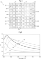
- FIGs. 6 to 9 each present the result of the measurement of the reflectances (Rf).
- the graphs each show leader lines and associated numbers to indicate the respective thicknesses (nm) of different reflective films 21.
- the reflectance was approximately 0.1 over the entire wavelength range when a reflective film 21 was absent on the first face 31 of the first glass sheet 11 (that is, the reflective film 21 had a thickness of 0).
- the reflectance reached 0.3 or more within the wavelength range of 300 nm to 400 nm (that is, the ultraviolet range) when the reflective film 21 had a thickness of 10 nm to 200 nm.
- the reflective films 21 may each have a thickness of not less than 10 nm and not more than 50 nm as illustrated in FIG. 6 .
- the reflective films 21 each having a thickness of not less than 10 nm and not more than 50 nm are thin but allow the reflective area 22 to have a particularly high ultraviolet reflectance as compared to the transmissive area 23. This reduces the cost of producing the glass panel 10, and causes birds to more likely perceive the glass panel 10.
- the reflective films 21 may each have a thickness of not less than 60 nm and not more than 100 nm as illustrated in FIG. 7 .
- the reflective films 21 each having a thickness of not less than 60 nm and not more than 100 nm allow the reflective area 22 to have a high reflectance not only in the ultraviolet range (that is, the wavelength range of 300 nm to 400 nm), but also in the visible light range (that is, the wavelength range of 400 nm to 780 nm), which is outside the ultraviolet range.
- the above thickness range thus allows the reflective area 22 to have a high reflectance for both ultraviolet light and visible light as compared to the transmissive area 23. This causes light reflected in the reflective area 22 to have a high luminance.
- Light reflected in the reflective area 22 has a luminance that varies according to the variation in the thickness of the reflective films 21. This luminance variation is unrelated to the difference described above with reference to FIG. 3 in the wavelength range of light reflected in the four types of reflective portions (A to D).
- the reflective films 21 may each have a thickness of not less than 140 nm and not more than 200 nm as illustrated in FIGs. 8 and 9 .
- the reflective films 21 each having a thickness of not less than 140 nm and not more than 200 nm allow the reflective area 22 to have a high reflectance not only in the ultraviolet range (that is, the wavelength range of 300 nm to 400 nm), but also in the visible light range (that is, the wavelength range of 400 nm to 780 nm), which is outside the ultraviolet range.
- the reflective films 21 each having a thickness of not less than 140 nm and not more than 200 nm allow the reflectance to have two distinct peaks in the ultraviolet range and the visible light range, respectively.
- the above thickness range thus allows the reflective area 22 to have a high reflectance for both ultraviolet light and visible light as compared to the transmissive area 23. This causes light reflected in the reflective area 22 to have a high luminance, thereby causing birds to more likely perceive the glass panel 10.
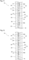
- Embodiment 2 is, as illustrated in FIG. 10 , a glass panel 10 including a plurality of reflective films 21 for a reflective area 22 on the second face 32 of the first glass sheet 11 and a low-e film as the heat insulator film 41 disposed on the entire third face 33 of the second glass sheet 12.
- Disposing a heat insulator film 41 on the third face 33 of the glass panel 10 as for the present embodiment allows the glass panel 10 to prevent escape of indoor heat for increased heat insulation.
- the glass panel 10 having a reflective area 22 on the second face 32 prevents the reflective films 21 from being exposed to outside air, and thereby allows the reflective area 22 to have a high weather resistance.
- disposing reflective films 21 on the first glass sheet 11 and a heat insulator film 41 on the second glass sheet 12 improves the yield of glass sheets, as compared to a case of disposing reflective films 21 and a heat insulator film 41 on a single glass sheet.
- Embodiment 3 as illustrated in FIG. 11 , includes a low-e film disposed on the entire second face 32 of the first glass sheet 11 as a heat barrier film 42 serving to reflect near-infrared light and a plurality of reflective films 21 for a reflective area 22 on the third face 33 of the second glass sheet 12.
- Disposing a heat barrier film 42 on the second face 32 of the glass panel 10 as for the present embodiment prevents the glass panel 10 from easily transmitting heat from outdoors to indoors for improved heat barrier property of the glass panel 10.
- the glass panel 10 having a reflective area 22 on the third face 33 prevents the reflective films 21 from being exposed to outside air, and thereby allows the reflective area 22 to have a high weather resistance.
- disposing a heat barrier film 42 on the first glass sheet 11 and reflective films 21 on the second glass sheet 12 improves the yield of glass sheets, as compared to a case of disposing reflective films 21 and a heat barrier film 42 on a single glass sheet.
- Embodiment 4 as illustrated in Fig. 12 , includes a low-e film disposed on the entire second face 32 of the first glass sheet 11 as a heat barrier film 42 and reflective films 21 on the front surface of the heat barrier film 42.
- Disposing a heat barrier film 42 on the second face 32 as for the present embodiment prevents easy transmission of heat from outdoors to indoors for improved heat barrier property.
- Disposing a reflective area 22 on the second face 32 means that the reflective area 22 are toward the outdoor side, thereby causing birds to more likely perceive the glass panel 10.
- the present variation includes reflective films 21 on the second face 32 of the first glass sheet 11 and a low-e film as a heat barrier film 42 disposed over the entire second face 32 of the first glass sheet 11 in such a manner as to cover the respective front surfaces of the reflective films 21.
- This allows the reflective area 22 to be separated from the columns 16 by the heat barrier film 42, and thereby prevents the reflective area 22 from coming into contact with and being damaged by the columns 16.
- This arrangement may alternatively be on the third face 33.
- the present disclosure is widely applicable to multi-glazed panels.
Landscapes
- Engineering & Computer Science (AREA)
- Structural Engineering (AREA)
- Civil Engineering (AREA)
- Life Sciences & Earth Sciences (AREA)
- Chemical & Material Sciences (AREA)
- Physics & Mathematics (AREA)
- Optics & Photonics (AREA)
- General Physics & Mathematics (AREA)
- Materials Engineering (AREA)
- Chemical Kinetics & Catalysis (AREA)
- General Chemical & Material Sciences (AREA)
- Geochemistry & Mineralogy (AREA)
- Organic Chemistry (AREA)
- Toxicology (AREA)
- Health & Medical Sciences (AREA)
- Architecture (AREA)
- Environmental Sciences (AREA)
- Zoology (AREA)
- Wood Science & Technology (AREA)
- Pest Control & Pesticides (AREA)
- Insects & Arthropods (AREA)
- Birds (AREA)
- Ceramic Engineering (AREA)
- Joining Of Glass To Other Materials (AREA)
- Catching Or Destruction (AREA)
Abstract
Description
- The present disclosure relates to a multi-glazed panel including a pair of glass sheets.
- A multi-glazed panel as a windowpane of a building lets birds fly toward nature reflected in the windowpane or indoor plants or the like visible through the windowpane and unfortunately collide with the windowpane.
- Patent Literature 1 discloses a multi-glazed panel including a glass sheet, an anti-reflective coating on an entire surface of the glass sheet, and a UV reflectance coating in a separated pattern over the surface of the glass sheet. Birds are known to have tetrachromatic vision, which covers the near-ultraviolet range. Birds, in other words, chromatically perceive light with wavelengths in the ultraviolet range (that is, the range of 300 nm to 400 nm), which is chromatically unperceivable by human beings. The multi-glazed panel disclosed in Patent Literature 1 includes a glass sheet provided with a UV reflectance coating in view of the color vision of birds to cause birds to more likely perceive the multi-glazed panel and thereby prevent collision by birds.
- Patent Literature 1
Japanese Translation ofPCT International Application, JP2016-520033A - The multi-glazed panel disclosed in Patent Literature 1 includes an anti-reflective coating and a UV reflectance coating such that the glass sheet has UV reflectance areas in a particular patten to produce the effect of causing birds to more likely perceive the multi-glazed panel. This effect, however, depends on the pattern of the UV reflectance coating. The multi-glazed panel still has room for improvement in terms of the function of preventing collision by birds.
- The above circumstances have led to a demand for a multi-glazed panel having an improved function of preventing collision by birds.
- A multi-glazed panel according to the present disclosure characteristically includes: a first glass sheet having a first face placeable to face outdoors and a second face opposite to the first face; a second glass sheet having a third face facing the second face and a fourth face opposite to the third face; and a plurality of columns in contact with the second face and the third face, wherein at least one of the first face, the second face, the third face, or the fourth face has (i) a reflective area provided with at least one reflective film serving to reflect ultraviolet light and (ii) a transmissive area serving to transmit ultraviolet light, and the plurality of columns include at least one column having an area that coincides with the at least one reflective film as viewed in a direction perpendicular to the first face.
- The multi-glazed panel configured as above includes a first glass sheet placeable to face outdoors, a second glass sheet placeable to face indoors, and a plurality of columns between the first glass sheet and the second glass sheet. One of the glass sheets has a reflective area provided with at least one reflective film serving to reflect ultraviolet light and a transmissive area serving to transmit ultraviolet light. The reflective area and the transmissive area cause birds to more likely see both nature reflected in the windowpane and indoor plants or the like visible through the windowpane. Further, the plurality of columns cause birds to more likely recognize the multi-glazed panel as an artificial object. These arrangements can prevent birds from colliding with the multi-glazed panel. Ultraviolet light has wavelengths that are chromatically unperceivable by human beings but are chromatically perceivable by birds. The first glass sheet, for example, being provided with at least one reflective film that serve to reflect ultraviolet light causes birds to more likely perceive the multi-glazed panel, without impairing its appearance.
- Further, with the above configuration, the plurality of columns include at least one column having an area that coincides with the at least one reflective film as viewed in the direction perpendicular to the first face. This allows the multi-glazed panel to include four types of light-reflecting portions, namely, a first reflective portion in which only a reflective area is present, a second reflective portion in which a reflective film and a column coincide with each other, a third reflective portion in which a transmissive area and a column coincide with each other, and a fourth reflective portion in which only a transmissive area is present. This causes birds to more likely recognize the multi-glazed panel as an artificial object, and thereby allows the multi-glazed panel to have an improved function of preventing collision by birds. The above four types of reflective portions serve to reflect light with different wavelengths. This difference is unrelated to the variation in the luminance of light reflected in the reflective area caused by the variation in the thickness of the at least one reflective film.
- The multi-glazed panel may further be arranged such that the reflective area includes a plurality of reflective films apart from each other at a predetermined interval, and the transmissive area has a maximum width of not less than 3 cm and not more than 20 cm.
- The transmissive area having a maximum width of not less than 3 cm and not more than 20 cm as above reliably causes birds to see both nature reflected in the windowpane and indoor plants or the like visible through the windowpane. This allows the multi-glazed panel to have a further improved function of preventing collision by birds.
- The multi-glazed panel may further be arranged such that the plurality of columns are evenly spaced from each other, and mutually adjacent columns among the plurality of columns have respective centers apart from each other by a distance of not less than 3 cm and not more than 20 cm.
- The above multi-glazed panel is arranged such that the plurality of columns are evenly spaced from each other and that mutually adjacent columns among the plurality of columns have respective centers apart from each other by a distance of not less than 3 cm and not more than 20 cm. This causes birds to more likely perceive the plurality of columns in the multi-glazed panel, and thereby allows the multi-glazed panel to have a further improved function of preventing collision by birds.
- The multi-glazed panel may further be arranged such that the plurality of columns are evenly spaced from each other, and the reflective area includes a plurality of reflective films apart from each other at a predetermined interval, and mutually adjacent reflective films among the plurality of reflective films are apart from each other by a distance different from a distance by which respective centers of mutually adjacent columns among the plurality of columns are apart from each other.
- The above multi-glazed panel is arranged such that the plurality of columns are evenly spaced from each other and that the plurality of reflective films are apart from each other by a distance different from the distance between the plurality of columns. This allows the four types of reflective portions to be in a complicated pattern, and thereby allows the multi-glazed panel to have a further improved function of preventing collision by birds.
- The multi-glazed panel may further be arranged such that the at least one reflective film is in a stripe shape.
- The at least one reflective film being in a stripe shape as above allows the reflective area to include portions next to each other. This in turn allows the multi-glazed panel to have a further improved function of preventing collision by birds.
- The multi-glazed panel may further be arranged such that the at least one reflective film is in a dot shape.
- The at least one reflective film being in a dot shape as above forms a minimally required reflective area on the multi-glazed panel, and reduces the cost of producing the multi-glazed panel.
- The multi-glazed panel may further be arranged such that the at least one reflective film includes titanium oxide.
- The at least one reflective film including titanium oxide as above provides a reflective area on the multi-glazed panel that serves to reflect more ultraviolet light.
- The multi-glazed panel may further be arranged such that the at least one reflective film has a thickness of not less than 10 nm and not more than 50 nm.
- The at least one reflective film having the above thickness allows the reflective area to have an ultraviolet reflectance higher than that of the transmissive area. This reduces the cost of producing the multi-glazed panel, and causes birds to more likely perceive the multi-glazed panel.
- The multi-glazed panel may further be arranged such that the at least one reflective film has a thickness of not less than 60 nm and not more than 100 nm.
- The at least one reflective film having the above thickness allows the reflective area to have a higher reflectance for both ultraviolet light and visible light than that of the transmissive area. This allows the multi-glazed panel to have a higher contrast, and thereby causes birds to more likely perceive the multi-glazed panel.
- The multi-glazed panel may further be arranged such that the at least one reflective film has a thickness of not less than 140 nm and not more than 200 nm.
- The at least one reflective film having the above thickness allows the reflective area to have an even higher reflectance for both ultraviolet light and visible light than that of the transmissive area. This allows the multi-glazed panel to have an even higher contrast, and thereby causes birds to even more likely perceive the multi-glazed panel.
- The multi-glazed panel may further include: a sealing section extending along an entire edge of each of the first glass sheet and the second glass sheet and enclosing a gap between the first glass sheet and the second glass sheet under reduced pressure.
- The above sealing section imparts heat insulation to the multi-glazed panel.
- The multi-glazed panel may further be arranged such that the plurality of columns, which are in contact with the second face and the third face, include at least one column that coincides with the reflective area as viewed in the direction perpendicular to the first face over a contact area which accounts for not less than 20% of a total of respective contact areas of the plurality of columns.
- The reflective area has a low ultraviolet transmittance and a high ultraviolet reflectance as compared to the transmissive area. Similarly, the reflective area is known to have a low near-infrared transmittance. The multi-glazed panel thus tends to have a low temperature in the reflective area as compared to the transmissive area. In view of that, the above multi-glazed panel is arranged such that the at least one column coincides with the reflective area, which tends to have a relatively low temperature as above, over a contact area which accounts for not less than 20% of the total of the respective contact areas of the plurality of columns. This means that the multi-glazed panel has a small amount of heat in that area of the glass sheets in which at least one column coincides with the reflective area, thereby reducing transfer of heat through the plurality of columns. The above arrangement thus allows the multi-glazed panel to have a low heat transmission coefficient (U-value) and maintain its heat insulation.
- The multi-glazed panel may further be arranged such that the plurality of columns, which are in contact with the second face and the third face, include at least one column that coincides with the reflective area as viewed in the direction perpendicular to the first face over a contact area which accounts for not less than 50% of a total of respective contact areas of the plurality of columns.
- The above multi-glazed panel is arranged such that the at least one column coincides with the reflective area over a contact area which accounts for not less than 50% of the total of the respective contact areas of the plurality of columns. This means that the multi-glazed panel has a smaller amount of heat in that area of the glass sheets in which at least one column coincides with the reflective area, thereby further reducing transfer of heat through the plurality of columns. The above arrangement thus allows the multi-glazed panel to have a lower heat transmission coefficient (U-value) and better maintain its heat insulation.
- The multi-glazed panel may further include: a heat insulator film disposed on the third face and serving to reflect far-infrared light, wherein the first face has the reflective area and the transmissive area.
- Disposing a heat insulator film on the third face of the second glass sheet as above allows the multi-glazed panel to prevent escape of indoor heat for increased heat insulation. Disposing a reflective area on the first face of the first glass sheet causes birds to more likely perceive the reflective film, and thereby allows the multi-glazed panel to have an improved function of preventing collision by birds. Further, disposing a reflective film on the first glass sheet of the multi-glazed panel and a heat insulator film on the second glass sheet thereof improves the yield of glass sheets, as compared to a case of disposing a reflective film and a heat insulator film on a single glass sheet.
- The multi-glazed panel may further include: a heat insulator film disposed on the third face and serving to reflect far-infrared light, wherein the second face has the reflective area and the transmissive area.
- Disposing a heat insulator film on the third face of the second glass sheet as above allows the multi-glazed panel to prevent escape of indoor heat for increased heat insulation. Disposing a reflective area on the second face of the first glass sheet prevents the reflective film from being exposed to outside air, and thereby allows the reflective area to have a high weather resistance. Further, disposing a reflective film on the first glass sheet of the multi-glazed panel and a heat insulator film on the second glass sheet thereof improves the yield of glass sheets, as compared to a case of disposing a reflective film and a heat insulator film on a single glass sheet.
- The multi-glazed panel may further include: a heat barrier film disposed on the second face and serving to reflect near-infrared light, wherein the third face has the reflective area and the transmissive area.
- Disposing a heat barrier film on the second face of the first glass sheet as above prevents the multi-glazed panel from easily transmitting heat from outdoors to indoors for improved heat barrier property of the multi-glazed panel. Disposing a reflective area on the third face of the second glass sheet prevents the reflective film from being exposed to outside air, and thereby allows the reflective area to have a high weather resistance. Further, disposing a heat barrier film on the first glass sheet of the multi-glazed panel and a reflective film on the second glass sheet thereof improves the yield of glass sheets, as compared to a case of disposing a reflective film and a heat barrier film on a single glass sheet.
- The multi-glazed panel may further be arranged such that the multi-glazed panel is configured to prevent collision by a bird.
- The reduced-pressure multi-glazed panel described above is effectively usable to prevent collision by birds and thereby protect birds, and maintains its appearance as well.
-
-
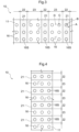
FIG. 1 is an exploded perspective view of a multi-glazed panel as Embodiment 1. -
FIG. 2 is a vertical cross-sectional view of the multi-glazed panel. -
FIG. 3 is a plan view of the multi-glazed panel. -
FIG. 4 is a plan view of a multi-glazed panel as Variation 1 of Embodiment 1. -
FIG. 5 is a plan view of a multi-glazed panel asVariation 2 of Embodiment 1. -
FIG. 6 is a graph that shows the relationship between different wavelengths and the respective reflectances of reflective films with different thicknesses. -
FIG. 7 is a graph that shows the relationship between different wavelengths and the respective reflectances of reflective films with different thicknesses. -
FIG. 8 is a graph that shows the relationship between different wavelengths and the respective reflectances of reflective films with different thicknesses. -
FIG. 9 is a graph that shows the relationship between different wavelengths and the respective reflectances of reflective films with different thicknesses. -
FIG. 10 is a vertical cross-sectional view of a multi-glazed panel asEmbodiment 2. -
FIG. 11 is a vertical cross-sectional view of a multi-glazed panel as Embodiment 3. -
FIG. 12 is a vertical cross-sectional view of a multi-glazed panel as Embodiment 4. -
FIG. 13 is a vertical cross-sectional view of a multi-glazed panel as a variation of Embodiment 4. -
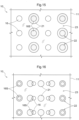
FIG. 14 is a plan view of a multi-glazed panel as an alternative embodiment. -
FIG. 15 is a plan view of a multi-glazed panel as an alternative embodiment. -
FIG. 16 is a plan view of a multi-glazed panel as an alternative embodiment. - The description below deals with a multi-glazed panel as an embodiment of the present disclosure with reference to drawings. The present embodiment described below is a reduced-pressure multi-glazed panel as an example multi-glazed panel. The present disclosure is, however, not limited to the embodiment below, and may be altered variously as long as such an alteration falls within the scope of the present disclosure.
- The description below deals with a reduced-pressure multi-glazed panel as Embodiment 1 with reference to drawings.
- As illustrated in
FIGs. 1 and 2 , the reduced-pressure multi-glazed panel (hereinafter referred to as "glass panel") 10 includes afirst glass sheet 11, asecond glass sheet 12 facing thefirst glass sheet 11, a sealingsection 14, and a plurality ofcolumns 16. The sealingsection 14 extends along the entire edge of each of thefirst glass sheet 11 and thesecond glass sheet 12. Thecolumns 16 are between thefirst glass sheet 11 and thesecond glass sheet 12. - The
first glass sheet 11 is float glass that has afirst face 31 and asecond face 32 opposite to thefirst face 31. Thesecond glass sheet 12 is float glass that has athird face 33 facing thesecond face 32 of thefirst glass sheet 11 and afourth face 34 opposite to thethird face 33. Theglass panel 10 as the present embodiment is designed such that thefirst face 31 of thefirst glass sheet 11 faces outdoors and that thefourth face 34 of thesecond glass sheet 12 faces indoors. - The
glass panel 10 has a predeterminedgap 13 between thefirst glass sheet 11 and thesecond glass sheet 12. Thegap 13 is enclosed by the sealingsection 14 under vacuum (which is an example of the "reduced pressure"). This imparts heat insulation to theglass panel 10. Thegap 13 is formed by (i) disposing a plurality ofcolumns 16 between thesecond face 32 of thefirst glass sheet 11 and thethird face 33 of thesecond glass sheet 12 to keep thesecond face 32 and thethird face 33 apart from each other by a predetermined distance and (ii) forming asealing section 14 along the entire edge of each of theglass sheets section 14 is made of, for example, a sealing material. A vacuum is created in thegap 13 for example by, after forming asealing section 14 along the edge of each of theglass sheets gap 13 through a suction port (not illustrated in the drawings) in thefirst glass sheet 11 and then closing the suction port with use of, for example, melted low-melting glass. Theglass panel 10 may have agap 13 enclosed under a pressure lower than atmospheric pressure. - As illustrated in
FIGs. 1 and 2 , thecolumns 16 are in contact with thesecond face 32 of thefirst glass sheet 11 and thethird face 33 of thesecond glass sheet 12. Thecolumns 16 are, for example, circular columns. - The
columns 16 are made of, for example, a ceramic material such as alumina and zirconia. Thecolumns 16 may contain a nanoparticle filler made of, for example, zirconia. Containing zirconia easily allows thecolumns 16 to have a low heat conductivity, a high heat resistance, and a high strength. Examples of the material of thecolumns 16 include ceramic nanoparticles (Al2O3, SiO2, ZrO2, SiC, Si3N4, and any combination thereof), a ceramic precursor such as SSQ and polysilazane, a sintered ceramic (such as Al2O3, SiO2, ZrO2, SiC, Si3N4, zircon, steatite, cordierite, and aluminum titanate), a glass (such as silica, soda lime, and borosilicate), a glass ceramic (crystallized glass), glass frit, glass beads or bubble glass, a metal (such as stainless steels SUS304, SUS430, and SUS410, iron, and nickel), a resin (such as a polyimide, polyamide, PEEK, and PTFE), and any combination thereof. Thecolumns 16 are each in contact with each of thesecond face 32 of thefirst glass sheet 11 and thethird face 33 of thesecond glass sheet 12 over a surface with a diameter of, for example, not less than 100 µm and not more than 1000 µm. Birds have great vision: It is not less than five times greater, or even not less than seven times greater depending on the species of birds, than that of human beings. Thecolumns 16 may be invisible to human beings, but are sufficiently visible to birds. Further, thecolumns 16 being in contact with each of thesecond face 32 and thethird face 33 over a surface with a diameter of not larger than 1000 µm allows theglass panel 10 to have a low heat transmission coefficient (U-value), thereby allowing theglass panel 10 to have improved heat insulation. - The
first face 31 of thefirst glass sheet 11 has (i) areflective area 22 provided withreflective films 21 serving to reflect ultraviolet light and (ii) atransmissive area 23 serving to transmit ultraviolet light. - The
reflective area 22 is provided withreflective films 21 each in the shape of a belt. As illustrated inFIGs. 1 to 3 , the present embodiment is configured such that thereflective films 21 extend in the gravitational direction (that is, the up-down direction inFIG. 3 ) and are apart from one another at predetermined intervals in the horizontal direction (that is, the left-right direction inFIG. 3 ), which is orthogonal to the gravitational direction. Thetransmissive area 23 is that area of thefirst face 31 of thefirst glass sheet 11 which is not provided with thereflective films 21. - The
reflective films 21 each include, for example, a plurality of layers on top of each other. The layers may each include tin oxide (SnO2) or silicon oxide (SiO2). Thereflective films 21 may each include, for example, tin oxide as a first layer, silicon oxide as a second layer, tin oxide doped with fluorine (F:SnO2) as a third layer, and silicon oxide as a fourth layer, arranged in this order from thefirst face 31. The first layer of tin oxide has a thickness of 5 nm to 100 nm (inclusive of the upper and lower limits; hereinafter the same applies), preferably 10 nm to 50 nm, more preferably 10 nm to 20 nm. The second layer of silicon oxide has a thickness of 5 nm to 100 nm, preferably 10 nm to 50 nm, more preferably 15 nm to 30 nm. The third layer of tin oxide dope with fluorine has a thickness of 5 nm to 200 nm, preferably 50 nm to 150 nm, more preferably 100 nm to 120 nm. The fourth layer of silicon oxide has a thickness of 5 nm to 200 nm, preferably 50 nm to 150 nm, more preferably 80 nm to 100 nm. Thereflective films 21 each include at least one of the first to fourth layers. - The
reflective films 21 may each include a layer of titanium dioxide (TiO2). The layer of titanium dioxide has a thickness of 10 nm to 100 nm, preferably 10 nm to 50 nm. Thereflective films 21 may each consist of a single layer of titanium oxide. Thereflective films 21 can each be produced by a thin-film depositing technique such as magnetron sputtering, CVD, PCVD, or sol-gel method. - The
reflective films 21 may each be produced by, for example, sequentially depositing SnO2 (first layer), SiO2 (second layer), F:SnO2 (third layer), SiO2 (fourth layer), and TiO2 onto thefirst face 31 of thefirst glass sheet 11. Thereflective films 21 each have a thickness of, for example, not less than 10 nm and not more than 200 nm. - It is known that while human beings have trichromatic vision (blue, green, and red), birds have tetrachromatic vision (ultraviolet, blue, green, and red). Birds thus perceive the environment with richer color vision than human beings.
- The present embodiment is arranged such that the
first glass sheet 11 of theglass panel 10 has afirst face 31 with areflective area 22 that reflects ultraviolet light and atransmissive area 23 that transmits ultraviolet light and that theglass panel 10 includes a plurality ofcolumns 16 between thefirst glass sheet 11 and thesecond glass sheet 12. Thereflective area 22 and thetransmissive area 23 cause birds to more likely see both nature reflected in thereflective area 22 and indoor plants or the like visible through theglass sheets columns 16 cause birds to more likely recognize theglass panel 10 as an artificial object. These arrangements can prevent birds from colliding with theglass panel 10. Ultraviolet light has wavelengths that are chromatically unperceivable by human beings but are chromatically perceivable by birds. Theglass panel 10 includingreflective films 21 that serve to reflect ultraviolet light causes birds to more likely perceive theglass panel 10. - As illustrated in
FIGs. 1 to 3 , thereflective films 21 are on thefirst face 31 in a striped pattern. Thereflective films 21 are apart from one another at predetermined intervals in the horizontal direction (left-right direction) of thefirst glass sheet 11 to form areflective area 22. Thereflective area 22 has a width of not less than 1 cm, preferably not less than 5 cm, more preferably not less than 10 cm. Thereflective films 21 for thereflective area 22 are apart from one another by a distance (that is, the distance between the mutually facing sides of mutually adjacent reflective films 21) of preferably not less than 3 cm and not more than 20 cm, more preferably not less than 5 cm and not more than 10 cm. This means that thetransmissive area 23 has a maximum width of not less than 3 cm and not more than 20 cm, preferably not less than 5 cm and not more than 10 cm. Thetransmissive area 23 having a maximum width of not less than 3 cm and not more than 20 cm reliably cause birds to see both nature reflected in thereflective area 22 and indoor plants or the like visible through theglass sheets transmissive area 23 having a maximum width of not less than 5 cm and not more than 10 cm means that thetransmissive area 23 has a width not larger than the width of a minimum area through which birds tend to pass (for example, an area with a dimension of 5 cm in the gravitational direction and a dimension of 10 cm in the horizontal direction). This allows theglass panel 10 to have an improved function of preventing collision by birds. - The
columns 16 include at least onecolumn 16 having anarea 16S that coincides with areflective film 21 as viewed in the direction perpendicular to thefirst face 31. The present embodiment is arranged such that approximately one-third of thecolumns 16 are each in contact with each of theglass sheets reflective film 21. This allows theglass panel 10 to include four types of light-reflecting portions as viewed in the direction perpendicular to thefirst face 31, namely, a first reflective portion in which only a reflective area 22 (reflective film 21) is present (indicated as "A" inFIG. 3 ), a second reflective portion in which areflective film 21 and acolumn 16 coincide with each other (indicated as "B" inFIG. 3 ), a third reflective portion in which atransmissive area 23 and acolumn 16 coincide with each other (indicated as "C" inFIG. 3 ), and a fourth reflective portion in which only atransmissive area 23 is present (indicated as "D" inFIG. 3 ). This causes birds to more likely recognize theglass panel 10 as an artificial object, and thereby allows theglass panel 10 to have a further improved function of preventing collision by birds. - The four types of reflective portions are specifically arranged as follows: The first reflective portion (A) serves to reflect strong ultraviolet light with wavelengths of 370 nm and therearound. The second reflective portion (B) serves to reflect strong ultraviolet light as well as visible light by means of the
column 16. The third reflective portion (C) serves to reflect weak ultraviolet light as well as visible light by means of thecolumn 16. The fourth reflective portion (D) serves to reflect weak ultraviolet light. The above four types of reflective portions (A to D) serve to reflect light with different wavelengths. This difference is unrelated to the below-described variation in the luminance of light reflected in thereflective area 22 caused by the variation in the thickness of thereflective films 21. - As illustrated in
FIGs. 1 to 3 , as viewed in the direction perpendicular to thefirst face 31, thecolumns 16 are evenly spaced from one another, and thereflective films 21 for thereflective area 22 are apart from one another at predetermined intervals. Mutually adjacentreflective films 21 are apart from each other by a distance different from the distance between the respective centers of mutuallyadjacent columns 16. Specifically, mutually adjacentreflective films 21 are apart from each other by a distance larger than the distance between the respective centers of mutuallyadjacent columns 16. - The present embodiment is arranged such that the
columns 16 are evenly spaced from one another and that thereflective films 21 are apart from one another by a distance different from the distance between thecolumns 16. This allows the four types of reflective portions to be in a complicated pattern, and thereby allows theglass panel 10 to have a further improved function of preventing collision by birds. - The
glass panel 10 is configured such that thecolumns 16 are in contact with thesecond face 32 and thethird face 33 and evenly spaced from one another. Mutuallyadjacent columns 16 have their respective centers apart from each other by a distance of, for example, not less than 3 cm and not more than 20 cm. Arranging thecolumns 16 as above in theglass panel 10 causes birds to more likely perceive thecolumns 16, and thereby allows theglass panel 10 to have a further improved function of preventing collision by birds. - The
glass panel 10 includes aheat insulator film 41 disposed on the entirethird face 33 of thesecond glass sheet 12 and serving to reflect far-infrared light. Theheat insulator film 41 is, for example, a low-emissivity (low-e) film. A low-e film is made of a single metal layer or two or more layers on top of each other selected from a metal layer, a metal oxide layer, a metal nitride layer, and a metal oxynitride layer. The metal layer is, as a preferable example, a silver layer. The metal oxide layer is, as a preferable example, a tin oxide layer, titanium oxide layer, or a zinc oxide layer. The metal nitride layer is, as a preferable example, a silicon nitride layer. The metal oxynitride layer is, as a preferable example, a silicon oxynitride layer. A low-e film should preferably be formed under vacuum such as by physical vapor deposition (PVD), particularly preferably by sputtering, which allows formation of a large, uniform film. - Disposing a
heat insulator film 41 on thethird face 33 as for the present embodiment allows thesecond glass sheet 12 to prevent escape of indoor heat for increased heat insulation. Disposing thereflective areas 22 on thefirst face 31 of thefirst glass sheet 11 causes birds to more likely perceive thereflective areas 22 on theglass panel 10, and thereby more effectively prevents birds from colliding with theglass panel 10. Further, disposingreflective films 21 on thefirst glass sheet 11 and aheat insulator film 41 on thesecond glass sheet 12 improves the yield of glass sheets, as compared to a case of disposingreflective films 21 and aheat insulator film 41 on a single glass sheet. - As illustrated in
FIG. 4 , theglass panel 10 may include for a reflective area 22 a plurality ofreflective films 21 apart from one another in the gravitational direction. The variation illustrated inFIG. 4 is, similarly to the above embodiment, arranged such that thereflective films 21 for thereflective area 22 are apart from one another by a distance of, for example, not less than 3 cm and not more than 20 cm. This means that thetransmissive area 23 has a maximum width of not less than 3 cm and not more than 20 cm. Thetransmissive area 23 having a maximum width of not less than 3 cm and not more than 20 cm allows theglass panel 10 to have an improved function of preventing collision by birds. - The
glass panel 10 may include a plurality ofreflective films 21 intersecting with one another. The variation illustrated inFIG. 5 includes a plurality ofreflective films 21 extending in the horizontal direction (left-right direction) and another plurality ofreflective films 21 extending in the gravitational direction (up-down direction) and intersecting with the abovereflective films 21. The variation thus has areflective area 22 in a grid pattern. The above arrangement allows thereflective area 22 to be in a grid pattern such that thetransmissive area 23 has (i) a width smaller than the width of a minimum area through which birds tend to pass (for example, smaller than 10 cm in the horizontal direction) and (ii) a length smaller than the length of a minimum area through which birds tend to pass (for example, smaller than 5 cm in the gravitational direction). This allows theglass panel 10 to have a further improved function of preventing collision by birds. - The
glass panel 10 as the present variation is arranged such that the plurality ofcolumns 16, which are in contact with thesecond face 32 and thethird face 33, includecolumns 16 that coincide with thereflective area 22 as viewed in the direction perpendicular to thefirst face 31 over respective contact areas which together account for not less than 50% of the total of the respective contact areas of all thecolumns 16. - The
reflective area 22 has a low ultraviolet transmittance and a high ultraviolet reflectance as compared to thetransmissive area 23. Similarly, thereflective area 22 is known to have a low near-infrared transmittance. Theglass panel 10 thus tends to have a low temperature in thereflective area 22 as compared to thetransmissive area 23. The present variation is arranged such that thecolumns 16 that coincide with thereflective area 22, which tends to have a relatively low temperature as above, over respective contact areas which together account for not less than 50% of the total of the respective contact areas of all thecolumns 16. This means that theglass panel 10 has a small amount of heat in those areas of theglass sheets columns 16 coincide with thereflective area 22, thereby reducing transfer of heat through thecolumns 16. The above arrangement thus allows theglass panel 10 to have a low heat transmission coefficient (U-value) and maintain its heat insulation. -
Variation 2 of Embodiment 1 described above is an example in which thecolumns 16 includecolumns 16 that coincide with thereflective area 22 as viewed in the direction perpendicular to thefirst face 31 over respective contact areas which together account for not less than 50% of the total of the respective contact areas of all thecolumns 16. Thecolumns 16 that coincide with thereflective area 22 may alternatively have respective contact areas which together account for not less than 20% of the total of the respective contact areas of all thecolumns 16. - The
glass panel 10 as Variation 3 also has a small amount of heat in those areas of theglass sheets columns 16 coincide with thereflective area 22, thereby reducing transfer of heat through thecolumns 16. The above arrangement thus allows theglass panel 10 to have a low heat transmission coefficient (U-value) and maintain its heat insulation. -
Reflective films 21 with thicknesses of 0 nm to 200 nm (in steps of 10 nm) were produced on a surface of a glass sheet with a thickness of 3.1 mm. The reflectance (Rf) of eachreflective film 21 was measured with respect to wavelengths of 300 nm to 800 nm for observation of variation in the reflectance. Thereflective films 21 were each a single layer of TiO2.FIGs. 6 to 9 each present the result of the measurement of the reflectances (Rf). The graphs each show leader lines and associated numbers to indicate the respective thicknesses (nm) of differentreflective films 21. - As illustrated in
FIG. 6 , the reflectance was approximately 0.1 over the entire wavelength range when areflective film 21 was absent on thefirst face 31 of the first glass sheet 11 (that is, thereflective film 21 had a thickness of 0). The reflectance reached 0.3 or more within the wavelength range of 300 nm to 400 nm (that is, the ultraviolet range) when thereflective film 21 had a thickness of 10 nm to 200 nm. - The
reflective films 21 may each have a thickness of not less than 10 nm and not more than 50 nm as illustrated inFIG. 6 . Thereflective films 21 each having a thickness of not less than 10 nm and not more than 50 nm are thin but allow thereflective area 22 to have a particularly high ultraviolet reflectance as compared to thetransmissive area 23. This reduces the cost of producing theglass panel 10, and causes birds to more likely perceive theglass panel 10. - The
reflective films 21 may each have a thickness of not less than 60 nm and not more than 100 nm as illustrated inFIG. 7 . Thereflective films 21 each having a thickness of not less than 60 nm and not more than 100 nm allow thereflective area 22 to have a high reflectance not only in the ultraviolet range (that is, the wavelength range of 300 nm to 400 nm), but also in the visible light range (that is, the wavelength range of 400 nm to 780 nm), which is outside the ultraviolet range. The above thickness range thus allows thereflective area 22 to have a high reflectance for both ultraviolet light and visible light as compared to thetransmissive area 23. This causes light reflected in thereflective area 22 to have a high luminance. Light reflected in thereflective area 22 has a luminance that varies according to the variation in the thickness of thereflective films 21. This luminance variation is unrelated to the difference described above with reference toFIG. 3 in the wavelength range of light reflected in the four types of reflective portions (A to D). - The
reflective films 21 may each have a thickness of not less than 140 nm and not more than 200 nm as illustrated inFIGs. 8 and9 . Thereflective films 21 each having a thickness of not less than 140 nm and not more than 200 nm allow thereflective area 22 to have a high reflectance not only in the ultraviolet range (that is, the wavelength range of 300 nm to 400 nm), but also in the visible light range (that is, the wavelength range of 400 nm to 780 nm), which is outside the ultraviolet range. In particular, thereflective films 21 each having a thickness of not less than 140 nm and not more than 200 nm allow the reflectance to have two distinct peaks in the ultraviolet range and the visible light range, respectively. This in turn allows light reflected in thereflective area 22 to have distinct luminance peaks. The above thickness range thus allows thereflective area 22 to have a high reflectance for both ultraviolet light and visible light as compared to thetransmissive area 23. This causes light reflected in thereflective area 22 to have a high luminance, thereby causing birds to more likely perceive theglass panel 10. -
Embodiment 2 is, as illustrated inFIG. 10 , aglass panel 10 including a plurality ofreflective films 21 for areflective area 22 on thesecond face 32 of thefirst glass sheet 11 and a low-e film as theheat insulator film 41 disposed on the entirethird face 33 of thesecond glass sheet 12. - Disposing a
heat insulator film 41 on thethird face 33 of theglass panel 10 as for the present embodiment allows theglass panel 10 to prevent escape of indoor heat for increased heat insulation. Theglass panel 10 having areflective area 22 on thesecond face 32 prevents thereflective films 21 from being exposed to outside air, and thereby allows thereflective area 22 to have a high weather resistance. Further, disposingreflective films 21 on thefirst glass sheet 11 and aheat insulator film 41 on thesecond glass sheet 12 improves the yield of glass sheets, as compared to a case of disposingreflective films 21 and aheat insulator film 41 on a single glass sheet. - Embodiment 3, as illustrated in
FIG. 11 , includes a low-e film disposed on the entiresecond face 32 of thefirst glass sheet 11 as aheat barrier film 42 serving to reflect near-infrared light and a plurality ofreflective films 21 for areflective area 22 on thethird face 33 of thesecond glass sheet 12. - Disposing a
heat barrier film 42 on thesecond face 32 of theglass panel 10 as for the present embodiment prevents theglass panel 10 from easily transmitting heat from outdoors to indoors for improved heat barrier property of theglass panel 10. Theglass panel 10 having areflective area 22 on thethird face 33 prevents thereflective films 21 from being exposed to outside air, and thereby allows thereflective area 22 to have a high weather resistance. Further, disposing aheat barrier film 42 on thefirst glass sheet 11 andreflective films 21 on thesecond glass sheet 12 improves the yield of glass sheets, as compared to a case of disposingreflective films 21 and aheat barrier film 42 on a single glass sheet. - Embodiment 4, as illustrated in
Fig. 12 , includes a low-e film disposed on the entiresecond face 32 of thefirst glass sheet 11 as aheat barrier film 42 andreflective films 21 on the front surface of theheat barrier film 42. - Disposing a
heat barrier film 42 on thesecond face 32 as for the present embodiment prevents easy transmission of heat from outdoors to indoors for improved heat barrier property. Disposing areflective area 22 on thesecond face 32 means that thereflective area 22 are toward the outdoor side, thereby causing birds to more likely perceive theglass panel 10. - The present variation, as illustrated in
Fig. 13 , includesreflective films 21 on thesecond face 32 of thefirst glass sheet 11 and a low-e film as aheat barrier film 42 disposed over the entiresecond face 32 of thefirst glass sheet 11 in such a manner as to cover the respective front surfaces of thereflective films 21. This allows thereflective area 22 to be separated from thecolumns 16 by theheat barrier film 42, and thereby prevents thereflective area 22 from coming into contact with and being damaged by thecolumns 16. This arrangement may alternatively be on thethird face 33. -
- (1) The embodiments described above are each an example including
glass sheets reflective films 21 extending in either the gravitational direction (up-down direction) or the horizontal direction (left-right direction). The plurality of belt-shapedreflective films 21 may alternatively extend obliquely to cross the gravitational direction (up-down direction) and the horizontal direction (left-right direction). - (2) As illustrated in
FIG. 14 , theglass panel 10 may includecolumns 16 each of which overlaps with areflective film 21 over anarea 16S. Further, as illustrated inFIG. 14 , mutually adjacentreflective films 21 among the plurality ofreflective films 21 may be apart from each other by a distance smaller than the distance by which mutuallyadjacent columns 16 among the plurality ofcolumns 16 are apart from each other. - (3) As illustrated in
FIG. 15 , thereflective films 21 may each be in the shape of a dot on a surface of either of theglass sheets reflective films 21 may also be apart from one another by a distance equal to or different from the distance by which thecolumns 16 are apart from one another. The dot-shapedreflective films 21 form a minimally requiredreflective area 22, and reduce the cost of producing theglass panel 10.FIG. 15 illustrates an example in which the respective centers of thereflective films 21 are apart from one another by a distance larger than the distance by which the respective centers of thecolumns 16 are apart from one another.FIG. 16 illustrates an example in which the respective centers of the dot-shapedreflective films 21 are apart from one another by a distance smaller than the distance by which the respective centers of thecolumns 16 are apart from one another. The example illustrated inFIG. 16 is further arranged such that thecolumns 16 include both (i)columns 16 each of which coincides entirely with areflective film 21 and (ii)columns 16 each of which overlaps with areflective film 21. Thereflective films 21 may further alternatively include both dot-shapedreflective films 21 and stripe-shapedreflective films 21. - (4) The embodiments described above are each an
example glass panel 10 having areflective area 22 on one of the first tothird faces 31 to 33 among the first tofourth faces 31 to 34. Thereflective area 22 may alternatively be on thefourth face 34. - (5) The embodiments described above are each an example including
glass sheets reflective films 21 disposed at regular intervals for areflective area 22. Thereflective films 21 may alternatively be disposed at irregular intervals. - (6) The embodiments described above are each an
example including columns 16 each in the shape of a cylinder. The shape of thecolumns 16 is, however, not limited to a cylinder, and may alternatively be, for example, a prism or an elliptic cylinder. - (7) The embodiments described above may each further include an anti-reflective film for the
transmissive area 23 on theglass sheet - The present disclosure is widely applicable to multi-glazed panels.
-
- 10
- Glass panel
- 11
- First glass sheet
- 12
- Second glass sheet
- 13
- Gap
- 14
- Sealing section
- 16
- Column
- 16S
- Area
- 21
- Reflective film
- 22
- Reflective area
- 23
- Transmissive area
- 31
- First face
- 32
- Second face
- 33
- Third face
- 34
- Fourth face
- 41
- Heat insulator film
- 42
- Hear barrier film
Claims (17)
- A multi-glazed panel, comprising:a first glass sheet having a first face placeable to face outdoors and a second face opposite to the first face;a second glass sheet having a third face facing the second face and a fourth face opposite to the third face; anda plurality of columns in contact with the second face and the third face,wherein at least one of the first face, the second face, the third face, or the fourth face has (i) a reflective area provided with at least one reflective film serving to reflect ultraviolet light and (ii) a transmissive area serving to transmit ultraviolet light, andthe plurality of columns include at least one column having an area that coincides with the at least one reflective film as viewed in a direction perpendicular to the first face.
- The multi-glazed panel according to claim 1, whereinthe reflective area includes a plurality of reflective films apart from each other at a predetermined interval, andthe transmissive area has a maximum width of not less than 3 cm and not more than 20 cm.
- The multi-glazed panel according to claim 1 or 2, whereinthe plurality of columns are evenly spaced from each other, andmutually adjacent columns among the plurality of columns have respective centers apart from each other by a distance of not less than 3 cm and not more than 20 cm.
- The multi-glazed panel according to any one of claims 1 to 3, whereinthe plurality of columns are evenly spaced from each other,the reflective area includes a plurality of reflective films apart from each other at a predetermined interval, andmutually adjacent reflective films among the plurality of reflective films are apart from each other by a distance different from a distance by which respective centers of mutually adjacent columns among the plurality of columns are apart from each other.
- The multi-glazed panel according to any one of claims 1 to 4, wherein
the at least one reflective film is in a stripe shape. - The multi-glazed panel according to any one of claims 1 to 5, wherein
the at least one reflective film is in a dot shape. - The multi-glazed panel according to any one of claims 1 to 6, wherein
the at least one reflective film includes titanium oxide. - The multi-glazed panel according to claim 7, wherein
the at least one reflective film has a thickness of not less than 10 nm and not more than 50 nm. - The multi-glazed panel according to claim 7, wherein
the at least one reflective film has a thickness of not less than 60 nm and not more than 100 nm. - The multi-glazed panel according to claim 7, wherein
the at least one reflective film has a thickness of not less than 140 nm and not more than 200 nm. - The multi-glazed panel according to any one of claims 1 to 10, further comprising:
a sealing section extending along an entire edge of each of the first glass sheet and the second glass sheet and enclosing a gap between the first glass sheet and the second glass sheet under reduced pressure. - The multi-glazed panel according to any one of claims 1 to 11, wherein
the plurality of columns, which are in contact with the second face and the third face, include at least one column that coincides with the at least one reflective area as viewed in the direction perpendicular to the first face over a contact area which accounts for not less than 20% of a total of respective contact areas of the plurality of columns. - The multi-glazed panel according to any one of claims 1 to 11, wherein
the plurality of columns, which are in contact with the second face and the third face, include at least one column that coincides with the at least one reflective area as viewed in the direction perpendicular to the first face over a contact area which accounts for not less than 50% of a total of respective contact areas of the plurality of columns. - The multi-glazed panel according to any one of claims 1 to 13, further comprising:a heat insulator film disposed on the third face and serving to reflect far-infrared light,wherein the first face has the reflective area and the transmissive area.
- The multi-glazed panel according to claims 1 or 13, further comprising:a heat insulator film disposed on the third face and serving to reflect far-infrared light,wherein the second face has the reflective area and the transmissive area.
- The multi-glazed panel according to claims 1 or 13, further comprising:a heat barrier film disposed on the second face and serving to reflect near-infrared light,wherein the third face has the reflective area and the transmissive area.
- The multi-glazed panel according to any one of claims 1 to 16, wherein
the multi-glazed panel is configured to prevent collision by a bird.
Applications Claiming Priority (2)
| Application Number | Priority Date | Filing Date | Title |
|---|---|---|---|
| JP2021056150 | 2021-03-29 | ||
| PCT/JP2022/013036 WO2022210073A1 (en) | 2021-03-29 | 2022-03-22 | Double-pane glass panel |
Publications (2)
| Publication Number | Publication Date |
|---|---|
| EP4317101A1 true EP4317101A1 (en) | 2024-02-07 |
| EP4317101A4 EP4317101A4 (en) | 2025-03-19 |
Family
ID=83455252
Family Applications (1)
| Application Number | Title | Priority Date | Filing Date |
|---|---|---|---|
| EP22780288.1A Pending EP4317101A4 (en) | 2021-03-29 | 2022-03-22 | DOUBLE-GLAZED GLASS PANEL |
Country Status (5)
| Country | Link |
|---|---|
| US (1) | US20240093550A1 (en) |
| EP (1) | EP4317101A4 (en) |
| JP (1) | JPWO2022210073A1 (en) |
| CN (1) | CN117120391A (en) |
| WO (1) | WO2022210073A1 (en) |
Cited By (2)
| Publication number | Priority date | Publication date | Assignee | Title |
|---|---|---|---|---|
| DE102025000097B3 (en) | 2025-01-12 | 2026-06-25 | Isophon Glas Gmbh | Laminated glass, methods for its manufacture and laminated glass arrangement |
| EP4775393A1 (en) | 2025-01-12 | 2026-07-15 | Isophon Glas GmbH | Laminated glass, method for its manufacture and glazing arrangement |
Families Citing this family (1)
| Publication number | Priority date | Publication date | Assignee | Title |
|---|---|---|---|---|
| DE102022134997A1 (en) * | 2022-12-29 | 2024-07-04 | Seen Ag | Multi-pane glass or insulating glass visible element, in particular window and/or facade element, manufacturing process and use of the multi-pane glass or insulating glass visible element |
Family Cites Families (8)
| Publication number | Priority date | Publication date | Assignee | Title |
|---|---|---|---|---|
| FR2889886A1 (en) * | 2005-08-19 | 2007-02-23 | Saint Gobain | Ultraviolet flat discharge lamp e.g. bronze lamp, for e.g. refrigerator, has flat glass plates delimiting inner space filled of gas, and pair of electrodes associated to one of glass plates, where electrodes are disposed outside inner space |
| US10871600B2 (en) * | 2012-12-17 | 2020-12-22 | Guardian Glass, LLC | Window for reducing bird collisions |
| GB201309386D0 (en) * | 2013-05-24 | 2013-07-10 | Pilkington Group Ltd | A Glazing |
| US9650290B2 (en) * | 2014-05-27 | 2017-05-16 | Centre Luxembourgeois De Recherches Pour Le Verre Et La Ceramique (C.R.V.C.) Sarl | IG window unit for preventing bird collisions |
| GB201409408D0 (en) * | 2014-05-28 | 2014-07-09 | Pilkington Group Ltd | A glazing |
| WO2017056421A1 (en) * | 2015-09-29 | 2017-04-06 | パナソニックIpマネジメント株式会社 | Glass panel unit and glass window |
| CN108137397A (en) * | 2015-09-29 | 2018-06-08 | 松下知识产权经营株式会社 | Glass panel unit, the windowpane with the glass panel unit and the method for manufacturing glass panel unit |
| JP6861614B2 (en) * | 2017-03-28 | 2021-04-21 | 大阪瓦斯株式会社 | Radiative cooling device and radiative cooling method |
-
2022
- 2022-03-22 JP JP2023511003A patent/JPWO2022210073A1/ja active Pending
- 2022-03-22 WO PCT/JP2022/013036 patent/WO2022210073A1/en not_active Ceased
- 2022-03-22 US US18/274,417 patent/US20240093550A1/en active Pending
- 2022-03-22 EP EP22780288.1A patent/EP4317101A4/en active Pending
- 2022-03-22 CN CN202280025795.4A patent/CN117120391A/en active Pending
Cited By (2)
| Publication number | Priority date | Publication date | Assignee | Title |
|---|---|---|---|---|
| DE102025000097B3 (en) | 2025-01-12 | 2026-06-25 | Isophon Glas Gmbh | Laminated glass, methods for its manufacture and laminated glass arrangement |
| EP4775393A1 (en) | 2025-01-12 | 2026-07-15 | Isophon Glas GmbH | Laminated glass, method for its manufacture and glazing arrangement |
Also Published As
| Publication number | Publication date |
|---|---|
| WO2022210073A1 (en) | 2022-10-06 |
| JPWO2022210073A1 (en) | 2022-10-06 |
| CN117120391A (en) | 2023-11-24 |
| US20240093550A1 (en) | 2024-03-21 |
| EP4317101A4 (en) | 2025-03-19 |
Similar Documents
| Publication | Publication Date | Title |
|---|---|---|
| US20240093550A1 (en) | Multi-glazed panel | |
| EP3148948B1 (en) | Ig window unit for preventing bird collisions | |
| EP3684613B1 (en) | Ig window unit including laminated substrates for preventing bird collisions | |
| US10526243B2 (en) | Bird safe glazing | |
| US20170208796A1 (en) | A glazing | |
| US20160137850A1 (en) | A glazing | |
| US9332862B2 (en) | Refrigerator door/window | |
| US11092726B1 (en) | Window unit having UV reflecting coating with high contrast ratio at large viewing angles for reducing bird collisions | |
| RU2747376C2 (en) | Substrate equipped with a set having thermal properties, its application and its manufacture | |
| US20240253330A1 (en) | Glazing for preventing bird collisions | |
| US12593834B2 (en) | Optically structured element for a bird protection glass, optical system and use of the optically structured element | |
| KR20250018166A (en) | Asymmetrical patterned reflective coating |
Legal Events
| Date | Code | Title | Description |
|---|---|---|---|
| STAA | Information on the status of an ep patent application or granted ep patent |
Free format text: STATUS: THE INTERNATIONAL PUBLICATION HAS BEEN MADE |
|
| PUAI | Public reference made under article 153(3) epc to a published international application that has entered the european phase |
Free format text: ORIGINAL CODE: 0009012 |
|
| STAA | Information on the status of an ep patent application or granted ep patent |
Free format text: STATUS: REQUEST FOR EXAMINATION WAS MADE |
|
| 17P | Request for examination filed |
Effective date: 20230927 |
|
| AK | Designated contracting states |
Kind code of ref document: A1 Designated state(s): AL AT BE BG CH CY CZ DE DK EE ES FI FR GB GR HR HU IE IS IT LI LT LU LV MC MK MT NL NO PL PT RO RS SE SI SK SM TR |
|
| DAV | Request for validation of the european patent (deleted) | ||
| DAX | Request for extension of the european patent (deleted) | ||
| REG | Reference to a national code |
Ref country code: DE Ref legal event code: R079 Free format text: PREVIOUS MAIN CLASS: C03C0027060000 Ipc: C03C0017340000 |
|
| A4 | Supplementary search report drawn up and despatched |
Effective date: 20250217 |
|
| RIC1 | Information provided on ipc code assigned before grant |
Ipc: E06B 3/67 20060101ALN20250211BHEP Ipc: A01M 29/32 20110101ALI20250211BHEP Ipc: A01M 29/08 20110101ALI20250211BHEP Ipc: E06B 3/663 20060101ALI20250211BHEP Ipc: E06B 3/66 20060101ALI20250211BHEP Ipc: C03C 27/06 20060101ALI20250211BHEP Ipc: C03C 17/34 20060101AFI20250211BHEP |