EP4317100A1 - Vacuum multilayered glass panel - Google Patents
Vacuum multilayered glass panel Download PDFInfo
- Publication number
- EP4317100A1 EP4317100A1 EP22779502.8A EP22779502A EP4317100A1 EP 4317100 A1 EP4317100 A1 EP 4317100A1 EP 22779502 A EP22779502 A EP 22779502A EP 4317100 A1 EP4317100 A1 EP 4317100A1
- Authority
- EP
- European Patent Office
- Prior art keywords
- suction hole
- sealing material
- pair
- glass
- peripheral edge
- Prior art date
- Legal status (The legal status is an assumption and is not a legal conclusion. Google has not performed a legal analysis and makes no representation as to the accuracy of the status listed.)
- Pending
Links
- 239000011521 glass Substances 0.000 title claims abstract description 250
- 239000003566 sealing material Substances 0.000 claims abstract description 238
- 230000002093 peripheral effect Effects 0.000 claims abstract description 109
- 230000000149 penetrating effect Effects 0.000 claims abstract description 5
- 230000008018 melting Effects 0.000 claims description 16
- 238000002844 melting Methods 0.000 claims description 16
- 238000012937 correction Methods 0.000 claims description 7
- 238000012360 testing method Methods 0.000 description 40
- 238000007789 sealing Methods 0.000 description 33
- 230000007423 decrease Effects 0.000 description 16
- 229910000679 solder Inorganic materials 0.000 description 15
- 229910052751 metal Inorganic materials 0.000 description 13
- 239000002184 metal Substances 0.000 description 13
- 125000006850 spacer group Chemical group 0.000 description 12
- 238000012546 transfer Methods 0.000 description 12
- 239000000463 material Substances 0.000 description 10
- 238000000034 method Methods 0.000 description 10
- 239000010936 titanium Substances 0.000 description 10
- 238000004140 cleaning Methods 0.000 description 9
- 229910052719 titanium Inorganic materials 0.000 description 7
- 238000010438 heat treatment Methods 0.000 description 6
- 238000004519 manufacturing process Methods 0.000 description 6
- 239000007788 liquid Substances 0.000 description 5
- PXHVJJICTQNCMI-UHFFFAOYSA-N Nickel Chemical compound [Ni] PXHVJJICTQNCMI-UHFFFAOYSA-N 0.000 description 4
- 229910052782 aluminium Inorganic materials 0.000 description 4
- 239000005329 float glass Substances 0.000 description 4
- 239000007769 metal material Substances 0.000 description 4
- 229910000831 Steel Inorganic materials 0.000 description 3
- 229910052804 chromium Inorganic materials 0.000 description 3
- 239000011651 chromium Substances 0.000 description 3
- 238000009413 insulation Methods 0.000 description 3
- 239000000203 mixture Substances 0.000 description 3
- 239000000565 sealant Substances 0.000 description 3
- 229910052710 silicon Inorganic materials 0.000 description 3
- 229910001220 stainless steel Inorganic materials 0.000 description 3
- 239000010959 steel Substances 0.000 description 3
- 239000005341 toughened glass Substances 0.000 description 3
- 229910052725 zinc Inorganic materials 0.000 description 3
- XEEYBQQBJWHFJM-UHFFFAOYSA-N Iron Chemical compound [Fe] XEEYBQQBJWHFJM-UHFFFAOYSA-N 0.000 description 2
- 229910000617 Mangalloy Inorganic materials 0.000 description 2
- RTAQQCXQSZGOHL-UHFFFAOYSA-N Titanium Chemical compound [Ti] RTAQQCXQSZGOHL-UHFFFAOYSA-N 0.000 description 2
- 239000003082 abrasive agent Substances 0.000 description 2
- 239000003463 adsorbent Substances 0.000 description 2
- 229910052787 antimony Inorganic materials 0.000 description 2
- 229910052797 bismuth Inorganic materials 0.000 description 2
- 239000000919 ceramic Substances 0.000 description 2
- 229910052802 copper Inorganic materials 0.000 description 2
- 238000007599 discharging Methods 0.000 description 2
- 230000007613 environmental effect Effects 0.000 description 2
- 230000005496 eutectics Effects 0.000 description 2
- 229910052733 gallium Inorganic materials 0.000 description 2
- 229910052738 indium Inorganic materials 0.000 description 2
- 229910052745 lead Inorganic materials 0.000 description 2
- 239000002075 main ingredient Substances 0.000 description 2
- 239000000155 melt Substances 0.000 description 2
- 229910044991 metal oxide Inorganic materials 0.000 description 2
- 150000004706 metal oxides Chemical class 0.000 description 2
- 229910052759 nickel Inorganic materials 0.000 description 2
- 229910000986 non-evaporable getter Inorganic materials 0.000 description 2
- 230000035939 shock Effects 0.000 description 2
- 229910052709 silver Inorganic materials 0.000 description 2
- 239000010935 stainless steel Substances 0.000 description 2
- 229910052718 tin Inorganic materials 0.000 description 2
- XLYOFNOQVPJJNP-UHFFFAOYSA-N water Chemical compound O XLYOFNOQVPJJNP-UHFFFAOYSA-N 0.000 description 2
- 239000005322 wire mesh glass Substances 0.000 description 2
- 241000189524 Baccharis halimifolia Species 0.000 description 1
- 229910001369 Brass Inorganic materials 0.000 description 1
- 229910001339 C alloy Inorganic materials 0.000 description 1
- VYZAMTAEIAYCRO-UHFFFAOYSA-N Chromium Chemical compound [Cr] VYZAMTAEIAYCRO-UHFFFAOYSA-N 0.000 description 1
- 229910000737 Duralumin Inorganic materials 0.000 description 1
- 229910000976 Electrical steel Inorganic materials 0.000 description 1
- -1 Inconel Chemical class 0.000 description 1
- VCUFZILGIRCDQQ-KRWDZBQOSA-N N-[[(5S)-2-oxo-3-(2-oxo-3H-1,3-benzoxazol-6-yl)-1,3-oxazolidin-5-yl]methyl]-2-[[3-(trifluoromethoxy)phenyl]methylamino]pyrimidine-5-carboxamide Chemical compound O=C1O[C@H](CN1C1=CC2=C(NC(O2)=O)C=C1)CNC(=O)C=1C=NC(=NC=1)NCC1=CC(=CC=C1)OC(F)(F)F VCUFZILGIRCDQQ-KRWDZBQOSA-N 0.000 description 1
- 229910018487 Ni—Cr Inorganic materials 0.000 description 1
- CBENFWSGALASAD-UHFFFAOYSA-N Ozone Chemical compound [O-][O+]=O CBENFWSGALASAD-UHFFFAOYSA-N 0.000 description 1
- 229910020994 Sn-Zn Inorganic materials 0.000 description 1
- 229910009069 Sn—Zn Inorganic materials 0.000 description 1
- CDBYLPFSWZWCQE-UHFFFAOYSA-L Sodium Carbonate Chemical compound [Na+].[Na+].[O-]C([O-])=O CDBYLPFSWZWCQE-UHFFFAOYSA-L 0.000 description 1
- 238000010521 absorption reaction Methods 0.000 description 1
- 238000003915 air pollution Methods 0.000 description 1
- 229910045601 alloy Inorganic materials 0.000 description 1
- 239000000956 alloy Substances 0.000 description 1
- XAGFODPZIPBFFR-UHFFFAOYSA-N aluminium Chemical compound [Al] XAGFODPZIPBFFR-UHFFFAOYSA-N 0.000 description 1
- 239000005354 aluminosilicate glass Substances 0.000 description 1
- 230000005540 biological transmission Effects 0.000 description 1
- 239000005388 borosilicate glass Substances 0.000 description 1
- 239000010951 brass Substances 0.000 description 1
- 239000010962 carbon steel Substances 0.000 description 1
- 229910000420 cerium oxide Inorganic materials 0.000 description 1
- XCNJCXWPYFLAGR-UHFFFAOYSA-N chromium manganese Chemical compound [Cr].[Mn].[Mn].[Mn] XCNJCXWPYFLAGR-UHFFFAOYSA-N 0.000 description 1
- VNTLIPZTSJSULJ-UHFFFAOYSA-N chromium molybdenum Chemical compound [Cr].[Mo] VNTLIPZTSJSULJ-UHFFFAOYSA-N 0.000 description 1
- VNNRSPGTAMTISX-UHFFFAOYSA-N chromium nickel Chemical compound [Cr].[Ni] VNNRSPGTAMTISX-UHFFFAOYSA-N 0.000 description 1
- 230000006835 compression Effects 0.000 description 1
- 238000007906 compression Methods 0.000 description 1
- 239000008367 deionised water Substances 0.000 description 1
- 229910021641 deionized water Inorganic materials 0.000 description 1
- 239000003599 detergent Substances 0.000 description 1
- 238000009792 diffusion process Methods 0.000 description 1
- 238000004090 dissolution Methods 0.000 description 1
- 238000005485 electric heating Methods 0.000 description 1
- 239000010419 fine particle Substances 0.000 description 1
- 230000008014 freezing Effects 0.000 description 1
- 238000007710 freezing Methods 0.000 description 1
- 239000005338 frosted glass Substances 0.000 description 1
- 230000017525 heat dissipation Effects 0.000 description 1
- 238000005338 heat storage Methods 0.000 description 1
- 229910001026 inconel Inorganic materials 0.000 description 1
- 239000004615 ingredient Substances 0.000 description 1
- 238000003780 insertion Methods 0.000 description 1
- 230000037431 insertion Effects 0.000 description 1
- 229910052742 iron Inorganic materials 0.000 description 1
- 238000005304 joining Methods 0.000 description 1
- 230000007774 longterm Effects 0.000 description 1
- 239000002932 luster Substances 0.000 description 1
- 239000011159 matrix material Substances 0.000 description 1
- 150000002739 metals Chemical class 0.000 description 1
- 230000003287 optical effect Effects 0.000 description 1
- BMMGVYCKOGBVEV-UHFFFAOYSA-N oxo(oxoceriooxy)cerium Chemical compound [Ce]=O.O=[Ce]=O BMMGVYCKOGBVEV-UHFFFAOYSA-N 0.000 description 1
- 230000000704 physical effect Effects 0.000 description 1
- 238000010791 quenching Methods 0.000 description 1
- 230000005855 radiation Effects 0.000 description 1
- 239000005368 silicate glass Substances 0.000 description 1
- 239000005361 soda-lime glass Substances 0.000 description 1
- 239000007787 solid Substances 0.000 description 1
- 238000007711 solidification Methods 0.000 description 1
- 230000008023 solidification Effects 0.000 description 1
- 238000003860 storage Methods 0.000 description 1
- 239000000126 substance Substances 0.000 description 1
- 238000004381 surface treatment Methods 0.000 description 1
- 238000005496 tempering Methods 0.000 description 1
- WFKWXMTUELFFGS-UHFFFAOYSA-N tungsten Chemical compound [W] WFKWXMTUELFFGS-UHFFFAOYSA-N 0.000 description 1
- 239000010937 tungsten Substances 0.000 description 1
- 229910052721 tungsten Inorganic materials 0.000 description 1
Images




Classifications
-
- C—CHEMISTRY; METALLURGY
- C03—GLASS; MINERAL OR SLAG WOOL
- C03C—CHEMICAL COMPOSITION OF GLASSES, GLAZES OR VITREOUS ENAMELS; SURFACE TREATMENT OF GLASS; SURFACE TREATMENT OF FIBRES OR FILAMENTS MADE FROM GLASS, MINERALS OR SLAGS; JOINING GLASS TO GLASS OR OTHER MATERIALS
- C03C27/00—Joining pieces of glass to pieces of other inorganic material; Joining glass to glass other than by fusing
- C03C27/06—Joining glass to glass by processes other than fusing
- C03C27/08—Joining glass to glass by processes other than fusing with the aid of intervening metal
-
- E—FIXED CONSTRUCTIONS
- E06—DOORS, WINDOWS, SHUTTERS, OR ROLLER BLINDS IN GENERAL; LADDERS
- E06B—FIXED OR MOVABLE CLOSURES FOR OPENINGS IN BUILDINGS, VEHICLES, FENCES OR LIKE ENCLOSURES IN GENERAL, e.g. DOORS, WINDOWS, BLINDS, GATES
- E06B3/00—Window sashes, door leaves, or like elements for closing wall or like openings; Layout of fixed or moving closures, e.g. windows in wall or like openings; Features of rigidly-mounted outer frames relating to the mounting of wing frames
- E06B3/66—Units comprising two or more parallel glass or like panes permanently secured together
- E06B3/6612—Evacuated glazing units
-
- E—FIXED CONSTRUCTIONS
- E06—DOORS, WINDOWS, SHUTTERS, OR ROLLER BLINDS IN GENERAL; LADDERS
- E06B—FIXED OR MOVABLE CLOSURES FOR OPENINGS IN BUILDINGS, VEHICLES, FENCES OR LIKE ENCLOSURES IN GENERAL, e.g. DOORS, WINDOWS, BLINDS, GATES
- E06B3/00—Window sashes, door leaves, or like elements for closing wall or like openings; Layout of fixed or moving closures, e.g. windows in wall or like openings; Features of rigidly-mounted outer frames relating to the mounting of wing frames
- E06B3/66—Units comprising two or more parallel glass or like panes permanently secured together
- E06B3/663—Elements for spacing panes
- E06B3/66304—Discrete spacing elements, e.g. for evacuated glazing units
-
- E—FIXED CONSTRUCTIONS
- E06—DOORS, WINDOWS, SHUTTERS, OR ROLLER BLINDS IN GENERAL; LADDERS
- E06B—FIXED OR MOVABLE CLOSURES FOR OPENINGS IN BUILDINGS, VEHICLES, FENCES OR LIKE ENCLOSURES IN GENERAL, e.g. DOORS, WINDOWS, BLINDS, GATES
- E06B3/00—Window sashes, door leaves, or like elements for closing wall or like openings; Layout of fixed or moving closures, e.g. windows in wall or like openings; Features of rigidly-mounted outer frames relating to the mounting of wing frames
- E06B3/66—Units comprising two or more parallel glass or like panes permanently secured together
- E06B3/663—Elements for spacing panes
- E06B3/66309—Section members positioned at the edges of the glazing unit
-
- E—FIXED CONSTRUCTIONS
- E06—DOORS, WINDOWS, SHUTTERS, OR ROLLER BLINDS IN GENERAL; LADDERS
- E06B—FIXED OR MOVABLE CLOSURES FOR OPENINGS IN BUILDINGS, VEHICLES, FENCES OR LIKE ENCLOSURES IN GENERAL, e.g. DOORS, WINDOWS, BLINDS, GATES
- E06B3/00—Window sashes, door leaves, or like elements for closing wall or like openings; Layout of fixed or moving closures, e.g. windows in wall or like openings; Features of rigidly-mounted outer frames relating to the mounting of wing frames
- E06B3/66—Units comprising two or more parallel glass or like panes permanently secured together
- E06B3/673—Assembling the units
- E06B3/67326—Assembling spacer elements with the panes
- E06B3/67334—Assembling spacer elements with the panes by soldering; Preparing the panes therefor
-
- E—FIXED CONSTRUCTIONS
- E06—DOORS, WINDOWS, SHUTTERS, OR ROLLER BLINDS IN GENERAL; LADDERS
- E06B—FIXED OR MOVABLE CLOSURES FOR OPENINGS IN BUILDINGS, VEHICLES, FENCES OR LIKE ENCLOSURES IN GENERAL, e.g. DOORS, WINDOWS, BLINDS, GATES
- E06B3/00—Window sashes, door leaves, or like elements for closing wall or like openings; Layout of fixed or moving closures, e.g. windows in wall or like openings; Features of rigidly-mounted outer frames relating to the mounting of wing frames
- E06B3/66—Units comprising two or more parallel glass or like panes permanently secured together
- E06B3/677—Evacuating or filling the gap between the panes ; Equilibration of inside and outside pressure; Preventing condensation in the gap between the panes; Cleaning the gap between the panes
- E06B3/6775—Evacuating or filling the gap during assembly
-
- Y—GENERAL TAGGING OF NEW TECHNOLOGICAL DEVELOPMENTS; GENERAL TAGGING OF CROSS-SECTIONAL TECHNOLOGIES SPANNING OVER SEVERAL SECTIONS OF THE IPC; TECHNICAL SUBJECTS COVERED BY FORMER USPC CROSS-REFERENCE ART COLLECTIONS [XRACs] AND DIGESTS
- Y02—TECHNOLOGIES OR APPLICATIONS FOR MITIGATION OR ADAPTATION AGAINST CLIMATE CHANGE
- Y02A—TECHNOLOGIES FOR ADAPTATION TO CLIMATE CHANGE
- Y02A30/00—Adapting or protecting infrastructure or their operation
- Y02A30/24—Structural elements or technologies for improving thermal insulation
- Y02A30/249—Glazing, e.g. vacuum glazing
-
- Y—GENERAL TAGGING OF NEW TECHNOLOGICAL DEVELOPMENTS; GENERAL TAGGING OF CROSS-SECTIONAL TECHNOLOGIES SPANNING OVER SEVERAL SECTIONS OF THE IPC; TECHNICAL SUBJECTS COVERED BY FORMER USPC CROSS-REFERENCE ART COLLECTIONS [XRACs] AND DIGESTS
- Y02—TECHNOLOGIES OR APPLICATIONS FOR MITIGATION OR ADAPTATION AGAINST CLIMATE CHANGE
- Y02B—CLIMATE CHANGE MITIGATION TECHNOLOGIES RELATED TO BUILDINGS, e.g. HOUSING, HOUSE APPLIANCES OR RELATED END-USER APPLICATIONS
- Y02B80/00—Architectural or constructional elements improving the thermal performance of buildings
- Y02B80/22—Glazing, e.g. vaccum glazing
Definitions
- the present invention relates to a depressurized multilayered glass panel.
- a depressurized multilayered glass panel includes a pair of opposing glass plates, in which a gap is provided between the pair of glass plates and the gap is brought into a depressurization state (e.g., Patent Literature 1).
- the peripheral edge of the pair of glass plates is provided with a peripheral edge sealing material joining the pair of glass plates over the entire periphery to hermetically seal the gap.
- One glass plate of the pair of glass plates is formed with a suction hole penetrating through the front and the back in the one glass plate and sucking the air in the gap.
- the suction hole and the periphery around the suction hole are covered with a suction hole sealing material in the state where the gap is depressurized via the suction hole, so that the suction hole is sealed.
- the suction hole is arranged at a position close to a corner portion of the peripheral edge of the pair of glass plates.
- Patent Literature 1 International Publication No. WO 2019/093323
- a 300°C molten solder (sealing material), for example, is sometimes charged as the suction hole sealing material in the sealing of the suction hole.
- the suction hole is arranged near the edge of the glass plate, the heat of the molten solder charged into the suction hole is transferred to the peripheral edge sealing material (e.g., solder) sealing a peripheral edge portion of the glass plate, raising the temperature of the peripheral edge sealing material.
- the melting point of the solder is usually around 200°C, which poses a risk of a decrease in the adhesion strength of the pair of glass plates when the temperature of a peripheral edge portion sealing material rises to reach 200°C or more.
- the suction hole when the suction hole is arranged at a position distant from the edge of the glass plate, the temperature rise of the peripheral edge sealing material is suppressed.
- the suction hole is positioned closer to the center of the glass plate, which poses a risk that the suction hole damages the appearance of the depressurized multilayered glass panel.
- the temperature rise of the peripheral edge sealing material is also affected by the weight of the suction hole sealing material besides the distance between the suction hole and the edge of the glass plate. More specifically, the heat quantity of the suction hole sealing material charged into the suction hole increases with an increase in the weight of the suction hole sealing material, and therefore the temperature of the peripheral edge sealing material is likely to rise.
- the suction hole is preferably arranged close to the peripheral edge of the pair of glass plates in terms of appearance.
- the heat quantity transferred from the suction hole sealing material to the peripheral edge sealing material via the glass plate increases when the molten suction hole sealing material is charged into the suction hole in a manufacturing process of the depressurized multilayered glass panel. Therefore, the peripheral edge sealing material subjected to the heat of the suction hole sealing material increases in temperature and partially melts in some cases. This reduces the adhesion strength of the pair of glass plates by the peripheral edge sealing material.
- the upper limit of the weight of the suction hole sealing material is prescribed based on a mathematical equation including the distance from the center of the suction hole to the edge of the glass plate.
- suction hole sealing material has a weight of 0.05 g or more and 5.00 g or less.
- the suction hole sealing material has a weight of less than 0.05 g, the suction hole cannot be properly sealed unless the size of the suction hole is reduced.
- a suction step of the gap of the pair of glass plates takes longer time. This poses a possibility that the depressurization state of the gap of the depressurized multilayered glass panel is insufficient, so that the workability in manufacturing the depressurized multilayered glass panel also decreases.
- the weight of the suction hole sealing material exceeds 5.00 g, the vicinity of the suction hole of the glass plate is excessively heated by the suction hole sealing material, which sharpy raises the temperature of the glass plate. Therefore, the glass plate of which temperature rises is subjected to a high-temperature thermal shock to be broken in some cases.
- the weight of the suction hole sealing material is preferably 0.05 g or more and 5.00 g or less.
- suction hole sealing material has a width in the plate surface direction of the pair of glass plates of 5 mm or more and 25 mm or less.
- the width of the suction hole sealing material is preferably small in terms of appearance.
- the width of the suction hole sealing material is 5 mm or more and 25 mm or less, and therefore the adjustment of the diameter of the suction hole and the width of the suction hole sealing material according to the size of the depressurized multilayered glass panel can make the suction hole sealing material less visible.
- the width of the suction hole sealing material is 5 mm or more and 25 mm or less, the transfer of the heat of the suction hole sealing material to the peripheral edge sealing material via the glass plate is suppressed and the adhesion strength of the pair of glass plates by the peripheral edge sealing material can be maintained.
- peripheral edge sealing material has the width in the plate surface direction of the pair of glass plates of 3 mm or more and 12 mm or less.
- the peripheral edge of the pair of glass plates can be properly sealed in the depressurized multilayered glass panel.
- peripheral edge sealing material has a melting point of 200°C or more.
- the melting point of the peripheral edge sealing material is 200°C or more as in this configuration, the melting point of the suction hole sealing material can be set to 200°C or more, and therefore the degree of freedom of an applicable suction sealing material increases.
- Another feature configuration is such that the pair of glass plates is formed in a rectangular shape, and the suction hole is arranged in a corner portion close to two sides of the one of the pair of glass plates.
- the arrangement of the suction hole in the corner portion close to the two sides of the rectangular glass plate as in this configuration can make the suction hole less visible in the depressurized multilayered glass panel.
- Another feature configuration is such that the pair of glass plates is formed in a rectangular shape and that the suction hole is arranged close to the vicinity of the center of one side of the one of the pair of glass plates.
- the arrangement of the suction hole close to the vicinity of the center of one side of the rectangular glass plate as in this configuration can make the suction hole less visible in the depressurized multilayered glass panel. Further, the arrangement of the suction hole sealing material charged into the suction hole close to only one side of the glass plate makes it possible to reduce a region of the peripheral edge sealing material of which temperature rises due to the heat of the suction hole sealing material. This can suppress the decrease in the adhesion strength of the peripheral edge sealing material in the glass plate formed with the suction hole.
- Another feature configuration is such that the suction hole sealing material is in contact with the plate surface of the other one of the pair of glass plates.
- the suction hole sealing material contacts the plate surface of the other one of the pair of glass plates as in this configuration, the suction hole sealing material is arranged over the pair of glass plates. Thus, the sealing state of the suction hole can be firmly held by the suction hole sealing material.
- a vacuum double glass panel is described as an example of the depressurized multilayered glass panel.
- the embodiments are not limited to the following embodiments, and can be variously altered without departing from the gist thereof.
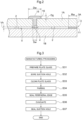
- a depressurized multilayered glass panel (hereinafter referred to as a glass panel) P includes a pair of opposing glass plates 1A, 1B and a plurality of spacers 2 (one example of the space holding member) arranged between the pair of glass plates 1A, 1B.
- the plurality of spacers 2 is arranged in a gap V formed between the pair of glass plates 1A, 1B.
- the plurality of spacers 2 is arranged at a constant interval on the plate surfaces of the pair of glass plates 1A, 1B.
- the glass panel P includes a peripheral edge sealing material 11 sealing the gap V in a peripheral edge 3 of the pair of glass plates 1A, 1B.
- the glass panel P also has a suction hole 4 penetrating through the front and the back of one glass plate 1A of the pair of glass plates 1A, 1B.
- the suction hole 4 is sealed with a suction hole sealing material 15 covering the suction hole 4 and the peripheral edge of the suction hole 4.
- the suction hole sealing material 15 seals the suction hole 4 in a state where the gap V is depressurized via the suction hole 4 in one of the pair of glass plates 1A, 1B.
- the two glass plates 1A, 1B each are transparent float glass.
- the gap V formed between the two glass plates 1A, 1B is depressurized to 1.33 Pa (1.0 ⁇ 10-2 Torr) or less.
- the gap V is depressurized by discharging the air thereinside to the outside via the suction hole 4 and sealed with the peripheral edge sealing material 11 and the suction hole sealing material 15 to maintain the above-described depressurization state.
- the spacer 2 has a cylindrical shape with a diameter of 0.3 to 1.0 mm and a height of 30 ⁇ m to 1.0 mm.
- the spacer 2 is formed of a material that does not buckle even when a compressive stress resulting from the atmospheric pressure acting on the glass plate 1A, 1B is loaded, e.g., a material with a compressive strength of 4.9 ⁇ 108 Pa (5 ⁇ 103 kgf/cm2) or more, preferably stainless steel (SUS304) or the like.
- the glass panel P is manufactured based on the flowchart illustrated in FIG. 3 .
- two glass blanks (not illustrated) with a predetermined thickness formed of float glass each are cut into a predetermined dimension, e.g., 1200 mm ⁇ 900 mm, to prepare the glass plates 1A, 1B having the same shape and the same size (Step S31).
- the suction hole 4 is bored by a drill or like into the glass plate 1A in the vicinity of any one of the four corners of the glass plate 1A (Step S32: boring step).
- the pair of glass plates 1A, 1B is cleaned using at least one of the methods of pure water brush cleaning, a liquid cleaning method, and optical cleaning in a space where the air pollution state can be chemically or physically controlled, such as a clean room or a chemical clean room (Step S33: cleaning step).
- a liquid cleaning method pure water, deionized water, or the like is used.
- the cleaning liquid contains an alkaline detergent or ozone water, for example.
- the cleaning liquid may also contain abrasives.
- the abrasives fine particles mainly containing cerium oxide as a main ingredient are used, for example.
- the plurality of spacers 2 is arranged in a matrix shape at a constant pitch Pd on the cleaned glass plate 1B where the suction hole 4 is not boded, and the cleaned glass plate 1A is superposed, thereby performing pairing of the glass plates 1A, 1B (Step S34).
- Step S35 peripheral edge sealing step
- a moving mechanism (not illustrated) is moved at a constant speed on a rail member (not illustrated) along the peripheral edge portion V1 of the gap V of the pair of glass plates 1A, 1B, and an introduction plate (not illustrated) is inserted into the gap V from a groove part 14 of the pair of glass plates 1A, 1B.
- the peripheral edge sealing material 11 enters the entire peripheral edge portion V1 of the pair of glass plates 1A, 1B via the introduction plate, so that the peripheral edge portion V1 of the pair of glass plates 1A, 1B is hermetically sealed with the peripheral edge sealing material 11.
- the groove part 14 as used herein is provided in a corner portion of the glass panel P and is an area where a corner portion on the gap V side of the pair of glass plates 1A, 1B is chamfered such that the introduction plate can be easily inserted into the gap V.
- Step S36 the evacuation of discharging the gas in the gap V to the outside is performed to reduce the pressure in the gap V to 1.33 Pa or less.
- an exhaust cup is attached to the principal surface on the atmospheric side of the glass plate 1A to cover the suction hole 4 in the vicinity of the suction hole 4, and the gas in the gap V is suctioned by a rotary pump or a turbomolecular pump, which is not illustrated, connected to this exhaust cup.
- the pump used in Step S36 is not limited to the rotary pump or the turbomolecular pump mentioned above, and any pump may be acceptable insofar as it can be connected to the exhaust cup and is capable of sucking the gas.
- Step S37 the suction hole sealing material 15 covering the suction hole 4 is dropped, and the glass surface in the vicinity of the suction hole 4 and the suction hole sealing material 15 are bonded to each other for sealing the suction hole 4 (Step S37). This tightly closes the gap V formed between the pair of glass plates 1A, 1B.
- Step S33 the steps from the cleaning of the principal surface of the pair of glass plates 1A, 1B (Step S33) to the bonding of the glass surface in the vicinity of the suction hole 4 and the suction hole sealing material 15 for sealing (Step S37) each are carried out in a depressurization space (autoclave), the pressure of which can be controlled to the air pressure.
- autoclave autoclave
- the peripheral edge sealing material 11 has a melting point of 200°C or more.
- the melting point of the peripheral edge sealing material 11 is 200°C or more
- the melting point of the suction hole sealing material 15 can be set to 200°C or more, which increases the degree of freedom of the applicable suction hole sealing material 15.
- solder with a melting point of 250°C or less for example, such as solder with a composition of 91.2Sn-8.8Zn (eutectic point temperature: 198°C) added with Ti, is used to seal the peripheral edge 3 of the pair of glass plates 1A, 1B.
- peripheral edge sealing material 11 is not limited thereto, and the peripheral edge 3 of the pair of glass plates 1A, 1B may be sealed using a sealant which is a metal material containing at least one material selected from the group consisting of Sn, Cu, In, Bi, Zn, Pb, Sb, Ga, and Ag and has a melting point of 250°C or less.
- the peripheral edge sealing material 11 may also contain, in place of Ti or in addition to Ti, at least one material selected from the group consisting of Al, Cr, and Si. This can enhance the adhesiveness between the peripheral edge sealing material 11 and glass components of the pair of glass plates 1A, 1B.
- the suction hole sealing material 15 has a melting point of 200°C or more.
- the suction hole 4 is sealed using, as the suction hole sealing material 15, solder with a melting point of 250°C or less, e.g., solder with a composition of 91.2Sn-8.8Zn (eutectic point temperature: 198°C) added with Ti.
- the suction hole sealing material 15 (solder) is not limited thereto, and the suction hole 4 may be sealed using a sealant which is a metal material containing at least one material selected from the group consisting of Sn, Cu, In, Bi, Zn, Pb, Sb, Ga, and Ag and has a melting point 250°C or less.
- the amount may be 90% or more.
- the Cu amount needs to be 0.1% or less.
- the suction hole sealing material 15 may also contain, in place of Ti or in addition to Ti, at least one material selected from the group consisting of Al, Cr, and Si.
- the suction hole sealing material 15 solder containing a component different from the component of the peripheral edge sealing material 11 may be used.
- Ti titanium
- the pressure of the gap V is reduced to 1.33 Pa or less, but the present invention is not limited thereto, and the pressure of the gap V may be reduced until the gap V is substantially evacuated. This can further enhance the thermal insulation performance of the glass panel P.
- the lower limit of a thickness Tg of the pair of glass plates 1A, 1B is 0.3 mm or more.
- the lower limit of the thickness Tg is preferably 0.5 mm or more and more preferably 1 mm or more.
- the upper limit of the thickness Tg of the pair of glass plates 1A, 1B is 15 mm or less.
- the upper limit of the thickness Tg is preferably 12 mm or less and more preferably 10 mm or less.
- the use of the thick glass plates 1A, 1B increases the rigidity of the glass plates 1A, 1B, and therefore the deformation quantity of the glass plates 1A, 1B due to external forces of the same magnitude decreases. Therefore, the tensile stress occurring near the surface on the side of the gap portion of the suction hole 4 decreases in the glass panel P, which enhances the long-term durability.
- the thickness Tg of the glass plates 1A, 1B is excessively large (exceeding 15 mm)
- the inflow amount of the suction hole sealing material 15 into the suction hole 4 decreases in the suction hole sealing. Therefore, the protrusion of the suction hole sealing material 15 of the surface on the side of the gap portion of the suction hole 4 decreases in size, making it difficult to reduce the tensile stresses occurring near the surface on the side of the gap portion of the suction hole 4.
- the pair of glass plates 1A, 1B is float glass, but is not limited thereto.
- various kinds of glass such as figured glass, frosted glass with a light diffusion function by surface treatment, wired glass, wired glass plate, tempered glass, double tempered glass, low reflection glass, high transmission glass plate, ceramic glass plate, and special glass with heat and UV absorption functions, or combinations thereof, or the like, for example, can be selected as appropriate for use according to the intended use as described above.
- soda silicate glass, soda lime glass, borosilicate glass, aluminosilicate glass, various kinds of crystallized glass, and the like are usable also for the composition of the pair of glass plates 1A, 1B.
- the groove part 14 is formed by chamfering a corner portion on the gap V side of the glass plates 1A, 1B in a planar shape, but is not limited thereto.
- the groove part 14 can be provided in the glass plates 1A, 1B by selecting any form as appropriate, e.g., chamfered in a curved shape, insofar as the form allows easy insertion of the introduction plate.
- a pitch Pd of the spacers 2 is 5 mm or more and 100 mm or less, preferably 5 mm or more and 80 mm or less, and more preferably 5 mm or more and 60 mm or less.
- the spacer 2 is formed of stainless steel, but is not limited thereto.
- the spacer 2 may be formed of those having high rigidity, e.g., metals, such as Inconel, iron, aluminum, tungsten, nickel, chromium, and titanium, alloys of carbon steel, chromium steel, nickel steel, nickel chromium steel, manganese steel, chromium manganese steel, chromium molybdenum steel, silicon steel, brass, solder, and duralumin, ceramic or glass, and the like.
- the spacer 2 is also not limited to the cylindrical shape and may also have various shapes, such as a rectangular shape or a spherical shape.
- a height Vh of the gap V is 30 ⁇ m to 1 mm. However, the height is substantially the same as the height of the spacers 2.
- an evaporable getter may be used to adsorb gas molecules in the gap V or a non-evaporable getter adsorbing and removing gas molecules by being heated and activated may be used, or the non-evaporable getter and the evaporable getter may be used in combination.
- getter materials (adsorbents) and adsorbent storage holes may be provided in two or more places.
- the peripheral edge sealing material 11 was formed using, but not limited to, a metal introduction apparatus.
- the peripheral edge sealing material 11 may be formed using any one of the following bonding methods of an anodic bonding method, an ultrasonic bonding method, a multi-stage bonding method, a laser bonding method, and a crimp bonding method. This can enhance the attachment property of the peripheral edge sealing material 11 to the pair of glass plates 1A, 1B.
- the peripheral edge sealing material 11 may be a material other than metal materials.
- a width Rw of the peripheral edge sealing material 11 as viewed in the thickness direction with respect to the plane of the glass panel P is 3 mm or more and 12 mm or less.
- the width Rw smaller than 3 mm makes it difficult to hold the sealing of the gap V of the glass panel P.
- the width Rw exceeding 12 mm increases the heat quantity transferred from one glass plate to the other glass plate through the peripheral edge sealing material 11, which reduces the insulation properties of the glass panel P.
- the glass plate 1A is set as the outdoor side and the glass plate 1B is set as the indoor side in the glass panel P illustrated in FIG. 2
- the heat on the outdoor side is transferred from the glass plate 1A to the glass plate 1B via the wide peripheral edge sealing material 11, which reduces the insulation properties of the glass panel P.
- the width Rw of the peripheral edge sealing material 11 is more preferably 3 mm or more and 5 mm or less. In this case, in addition to the fact that the sealing of the gap V of the glass panel P can be held, the heat transfer quantity by the peripheral edge sealing material 11 can be further reduced.
- a part where the suction hole sealing material 15 after sealing protrudes from the surface on the atmospheric side of the glass plate 1A is defined as a protrusion portion 16.
- a diameter Dw of the protrusion portion 16 is 5 mm or more and 25 mm. More specifically, the suction hole sealing material 15 has a width in the plate surface direction of the pair of glass plates 1A, 1B of 5 mm or more and 25 mm or less. The diameter Dw is more preferably 5 mm or more and 15 mm. However, the diameter Dw of the protrusion portion 16 is larger than a suction hole diameter Sw described below in any case.
- a thickness Dg of the protrusion portion 16 is 0.1 mm or more and 20 mm or less and preferably 0.1 mm or more and 10 mm or less.
- the suction hole diameter Sw is 1 mm or more and 10 mm or less.
- the suction hole diameter Sw is preferably 2 mm or more and 5 mm or less.
- the suction hole diameter Sw is desirably larger than the glass thickness and 10 mm or less. This is so that the air is passed through the suction hole 4 in air-quench tempering.
- An edge portion of at least one of an upper portion and at least a lower portion of the suction hole 4 may be formed in a curved shape or chamfered (the edge portion may be provided with a minute surface).
- the close contact property of the protrusion portion 16 formed around the suction hole 4 on the surface on the atmospheric side of the one glass plate 1A with the surface on the atmospheric side of the one glass plate 1A is important.
- the protrusion portion 16 sufficiently adheres to the one glass plate 1A when the metallic luster of the suction hole sealing material 15 is sufficiently observed when viewed from the back side of the one glass plate 1A, and the depressurization state in the gap V is maintained for a long time.
- external forces such as wind pressure and pressure in wipe-cleaning, act on the glass plate 1A.
- the protrusion portion 16 of the suction hole sealing material 15 to the glass plate 1A is peeled off.
- the suction hole sealing material 15 As the main ingredient of the suction hole sealing material 15, Sn is 72% to 99.9%, and any one of ingredients of Zn, Al, Si, and Ti is contained and the lead content is less than 0.1% in terms of percent by weight.
- the suction hole sealing material 15 may be a material other than metal materials.
- a sealing device 50 for sealing the suction hole 4 with the suction hole sealing material 15 is described based on FIGS. 4 and 5 .
- the sealing device 50 has a heating section 60, a sharp tip member 70, and a molten metal guiding section 80.
- the heating section 60 heats the suction hole sealing material 15 in a solid state to its melting point.
- the sharp tip member 70 has a push-in pin shape that can be pierced into the surface of the suction hole sealing material 15, the corners of which are rounded due to surface tension by being heated and melted in the heating section 60.
- the molten metal guiding section 80 guides the molten metal flowing out of a pierced hole of the surface of the suction hole sealing material 15 formed by the sharp tip member 70 to the suction hole 4.
- the molten metal guiding section 80 is provided with a funnel-shaped metal receiving tool 90 capable of receiving the suction hole sealing material 15.
- the receiving tool 90 is configured to be heatable by an electric heating wire wound around its periphery.
- the molten metal guiding section 80 is further provided with a supply outlet 100 guiding the molten metal to the suction hole 4 in a lower part of the receiving tool 90.
- the sharp tip member 70 is arranged above the receiving tool 90 via a compression spring 110.
- the sealing device 50 is provided with an operation mechanism 120 capable of vertically piercing the molten suction hole sealing material 15 in a lower part by pushing the pin tip of the sharp tip member 70 downward.
- the sealing device 50 further has a cup 130 closely contactable with the glass plate 1A to surround the suction hole 4 and formed such that the heating section 60 and the molten metal guiding section 80 can be stored inside the cup 130.
- the cup 130 is further provided with an air intake section (not illustrated) capable of depressurizing the inner space of the cup 130 and a pin push-in operation device 140 capable of operating the operation mechanism 120 from the outside of the cup 130 with the inside of the cup 130 in an airtight state.
- the suction hole sealing material 15 heated and melted by the heating section 60 becomes a liquid mass having substantially rounded corners due to surface tension.
- an oxide film 150 is formed on the surface of the suction hole sealing material 15, for example, like the thin skin of an egg, the surface is pierced by the sharp tip member 70, so that a hole is formed in a pierced portion of the oxide film 150 and the molten metal mainly flow out from the pierced portion (see FIG. 5 ).
- the flowing-out molten metal is guided to the suction hole 4 by the molten metal guiding section 80, and therefore the mixing of the metal oxide in the suction hole 4 is easily prevented. Accordingly, the suction hole sealing material 15 is bonded to the glass in a state where the metal oxide is not mixed in the suction hole 4 and the glass surface around the suction hole 4, and the airtightness of the gap V can be ensured.
- the suction hole sealing material 15 (e.g., "solder") of about 300°C is charged into the suction hole 4 under the condition of 195°C, for example.
- the suction hole 4 is away from an edge (end surface) 3A of the glass plate 1A by 50 mm, for example.
- the temperature of the peripheral edge sealing material 11 increases with a decrease in the distance between the suction hole 4 and the edge 3A of the glass plate 1A.
- the same "solder" as that of the suction hole sealing material 15 is used in some cases, which poses a risk that, when the temperature of the peripheral edge sealing material 11 reaches a temperature equal to or higher than the melting point (e.g., 200°C), the peripheral edge sealing material 11 partially melts.
- the following test was carried out to evaluate the influence when the distance of 50 mm from the edge 3A of the glass plate 1A is reduced and the influence of the weight of the suction hole sealing material 15.
- FIG. 6 illustrates a part of a depressurized multilayered glass panel used for the test and the dimension of the depressurized multilayered glass panel.
- the pair of glass plates 1A, 1B each is float glass with a plate thickness of 3.1 (mm).
- the suction hole 4 is formed in one of the pair of glass plates 1A, 1B.
- the peripheral edge sealing material 11 and the suction hole sealing material 15 are both Sn-Zn alloy solders with a melting point of 200°C, a density of 0.0073 (g/mm 3 ), and a specific heat of 243,000 (J/g ⁇ K). As illustrated in FIG.
- the diameter of the suction hole 4 was set to 1.4 (mm) and the peripheral edge sealing material 11 was arranged in the peripheral edge 3 of the pair of glass plates 1A, 1B and between both of the pair of glass plates 1A, 1B with a dimension of 5 (mm) in width and 0.2 (mm) in thickness.
- the suction hole sealing material 15 had the weight of 4.63 (g), and was charged into the suction hole 4 and arranged in a region of 9 (mm) in diameter and 10 (mm) in height on the upper surface of the glass plate 1A.
- the temperature rise of the peripheral edge sealing material 11 when the suction hole sealing material 15 was charged into the suction hole 4 to seal the suction hole 4 was measured.
- the distance from the edge 3A of the glass plate 1A to the center of the suction hole 4 (hereafter abbreviated to as "edge distance") was set to 10 (mm), 15 (mm), 20 (mm), 25 (mm), 50 (mm) in Test Examples 1 to 5, respectively.
- the charging of the suction hole sealing material 15 into the suction hole 4 was carried out in an environmental condition of 195°C, and the temperature rise of the peripheral edge sealing material 11 at that time was measured.
- the test results of Test 1 are illustrated in Table 1 and FIG. 7 .
- the maximum temperature of the peripheral edge sealing material 11 varied from 195.1°C to 205.4°C in Test Examples 1 to 5.
- Test Example 1 edge distance: 10 mm
- Test Examples 2 to 5 all had the temperature rise quantity of less than 5°C.
- the edge distances were specified to 10 (mm) and 15 (mm), and the temperature rise of the peripheral edge sealing material 11 was measured in the environmental condition of 195°C by varying the weight of the suction hole sealing material 15 in each edge distance.
- test samples 1 to 3 were used.
- test samples 2 to 4 were used.
- the weight of the suction hole sealing material 15 in each of test samples 1 to 4 is as illustrated in Table 2 below.
- the test results of Test 2 are illustrated in Table 2 and FIG. 8 .
- the maximum temperature of the peripheral edge sealing material 11 increased from 198.2°C to 205.4°C with an increase in the weight of the suction hole sealing material 15 from about 1.0 g to about 4.6 g.
- the maximum temperature of the peripheral edge sealing material 11 increased from 197.2°C to 200.0°C with an increase in the weight of the suction hole sealing material 15 from about 2.0 g to about 6.1 g.
- the initial temperature (ambient temperature) of the peripheral edge sealing material 11, 195°C, is represented by "To".
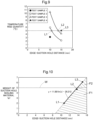
- the three edge distances L1 (test sample 2), L2 (test sample 3), L3 (test sample 4) where the temperature rise quantity is 5°C illustrated in FIG. 9 and the weight of the suction hole sealing material 15 in each edge distance are plotted in a graph illustrated in FIG. 10 , and the three points (L1, L2, L3) are connected with an approximate straight line.
- the approximate straight line represents the upper limit weight of the suction hole sealing material 15 in each edge distance.
- a heat transfer quantity E (W) to the peripheral edge sealing material 11 via the glass plate 1A by the suction hole sealing material 15 can be calculated by Equation (1) below based on a calculation equation for the heat transfer quantity based on a temperature difference between the inner diameter side and the outer diameter side of the cylinder.
- E 2 ⁇ ⁇ C ⁇ D ⁇ H / In A / B
- a (mm) is the outer radius (i.e., the distance from the center of the suction hole 4 to the edge 3A).
- B (mm) is the radius of the suction hole 4.
- H (mm) is the height of the suction hole 4 (i.e., the thickness of the glass plate 1A).
- C (W/mmK) is the thermal conductivity of the glass plate 1A.
- Equation (2) K 1 ⁇ 2 ⁇ ⁇ C ⁇ D ⁇ H / In A / B
- Equation (3) a heat quantity E2 usable for the temperature rise of the peripheral edge sealing material 11 in the suction hole sealing material 15 is derived by Equation (3) below.
- E 2 N ⁇ ⁇ T ⁇ W 1
- N J/g ⁇ K
- ⁇ T °C
- W1 kg
- N 243,000 (J/g ⁇ K)
- the heat transfer quantities E, E1 decrease with an increase in In(A/B) approximately corresponding to the distance from the edge 3A to the suction hole 4 (edge distance). More specifically, the heat transfer quantities E, E1 are inversely proportional to the edge distance.
- the heat quantity E2 which is the generation source of the heat transfer quantities E, E1 needs to increase to maintain the heat transfer quantities E, E1 with an increase in the edge distance. More specifically, the heat quantity E2 can be increased in proportion to the edge distance.
- a permissible heat quantity E3 according to the edge distance can be calculated by Equation (4) below using a correction coefficient "K2" and "Wmax" as the upper limit weight of the suction hole sealing material 15.
- the weight of the suction hole sealing material 15 where the temperature rise of the peripheral edge sealing material 11 is 5°C or less corresponding to the edge distance is included in regions F1, F2 on the right side of the approximate straight line in FIG. 10 , and the upper limit can be set based on Equation (4) above.
- the weight of the suction hole sealing material 15 charged into the suction hole 4 of the glass plate 1A can be properly set in the glass panel P, and the temperature rise of the peripheral edge sealing material 11 by the suction hole sealing material 15 in the manufacturing of the glass panel P can be suppressed.
- the glass panel P can prevent the decrease in the adhesion strength of the peripheral edge sealing material 11 and maintain the adhesion strength of the pair of glass plates 1A, 1B by the peripheral edge sealing material 11.
- the regions F1, F2 are the weight ranges of the suction hole sealing material 15 where the temperature rise quantity is 5°C or less in the predetermined edge distances.
- the region F2 beyond a boundary line W of 5 (g) it cannot be said that the weight of the suction hole sealing material 15 falls within a proper range for the following reasons.
- the weight W of the suction hole sealing material 15 is preferably 0.05 g or more and 5.00 g or less.
- the suction hole 4 cannot be properly performed unless the size of the smaller suction hole 4 is reduced, and, when the suction hole 4 is small, a suction step of the gap V takes longer time. This poses a possibility that the depressurization state of the gap V becomes insufficient in the glass panel P, which also reduces the workability in manufacturing the glass panel P.
- the suction hole sealing material 15 charged at 300°C has a temperature difference of 105°C from the glass plate 1A with a temperature of 195°C. Therefore, the heat quantity proportional to the weight of the suction hole sealing material 15 sharply raises the temperature of a part of the glass plate 1A.
- the glass plate 1A of which temperature has risen is subjected to a high-temperature thermal shock in the suction hole 4 to be broken in some cases.
- the upper limit weight (Wmax) of the suction hole sealing material 15 is preferably 5.00 g or less.
- the weight W of the suction hole sealing material 15 is more preferably 0.50 g or more and 4.00 g or less and still more preferably 1.00 g or more and 3.00 g or less from the viewpoints of suppressing the temperature rise of the glass plate 1A and suppressing the cost.
- the suction hole sealing material 15 is charged into the suction hole 4 using, for example, the sealing device 50 illustrated in FIGS. 4 and 5 .
- the sealing device 50 illustrated in FIGS. 4 and 5 .
- the oxide film 150 remains in the sealing device 50 and the remaining amount of the oxide film 150 is not constant.
- the weight of the suction hole sealing material 15 set in the sealing device 50 is not the same as that of the suction hole sealing material 15 actually charged into the suction hole 4, e.g., when 4.00 g of the suction hole sealing material 15 is charged into the suction hole 4, the suction hole sealing material 15 with a weight of more than 4.00 g needs to be set in the sealing device 50. Therefore, it is preferable for the sealing device 50 to be able to control the weight of the suction hole sealing material 15 actually charged into the suction hole 4.
- the suction hole 4 is arranged in the vicinity of the center along one side 3A1 (end surface) of one of the pair of glass plates 1A, 1B formed in a rectangular shape as illustrated in FIG. 11 . Also when the suction hole 4 is arranged at that position, the suction hole 4 can be made less visible in the glass panel P. Further, due to the fact that the suction hole sealing material 15 charged into the suction hole 4 is arranged close to only the one side 3A1 of the glass plate 1A, a region of the peripheral edge sealing material 11 of which temperature rises by the heat of the suction hole sealing material 15 can be reduced. This can suppress the decrease in the adhesion strength of the peripheral edge sealing material 11 in the glass plate 1A formed with the suction hole 4.
- the present invention is widely usable for the depressurized multilayered glass panel.
Landscapes
- Engineering & Computer Science (AREA)
- Civil Engineering (AREA)
- Structural Engineering (AREA)
- Chemical & Material Sciences (AREA)
- Ceramic Engineering (AREA)
- Life Sciences & Earth Sciences (AREA)
- Chemical Kinetics & Catalysis (AREA)
- General Chemical & Material Sciences (AREA)
- Geochemistry & Mineralogy (AREA)
- Materials Engineering (AREA)
- Organic Chemistry (AREA)
- Joining Of Glass To Other Materials (AREA)
- Securing Of Glass Panes Or The Like (AREA)
Abstract
Description
- The present invention relates to a depressurized multilayered glass panel.
- A depressurized multilayered glass panel includes a pair of opposing glass plates, in which a gap is provided between the pair of glass plates and the gap is brought into a depressurization state (e.g., Patent Literature 1). The peripheral edge of the pair of glass plates is provided with a peripheral edge sealing material joining the pair of glass plates over the entire periphery to hermetically seal the gap. One glass plate of the pair of glass plates is formed with a suction hole penetrating through the front and the back in the one glass plate and sucking the air in the gap. The suction hole and the periphery around the suction hole are covered with a suction hole sealing material in the state where the gap is depressurized via the suction hole, so that the suction hole is sealed.
- In the depressurized multilayered glass panel described in
Patent Literature 1, the suction hole is arranged at a position close to a corner portion of the peripheral edge of the pair of glass plates. - Patent Literature 1: International Publication No.
WO 2019/093323 - In the depressurized multilayered glass panel described in
Patent Literature 1, a 300°C molten solder (sealing material), for example, is sometimes charged as the suction hole sealing material in the sealing of the suction hole. In this case, when the suction hole is arranged near the edge of the glass plate, the heat of the molten solder charged into the suction hole is transferred to the peripheral edge sealing material (e.g., solder) sealing a peripheral edge portion of the glass plate, raising the temperature of the peripheral edge sealing material. The melting point of the solder is usually around 200°C, which poses a risk of a decrease in the adhesion strength of the pair of glass plates when the temperature of a peripheral edge portion sealing material rises to reach 200°C or more. On the other hand, when the suction hole is arranged at a position distant from the edge of the glass plate, the temperature rise of the peripheral edge sealing material is suppressed. However, the suction hole is positioned closer to the center of the glass plate, which poses a risk that the suction hole damages the appearance of the depressurized multilayered glass panel. The temperature rise of the peripheral edge sealing material is also affected by the weight of the suction hole sealing material besides the distance between the suction hole and the edge of the glass plate. More specifically, the heat quantity of the suction hole sealing material charged into the suction hole increases with an increase in the weight of the suction hole sealing material, and therefore the temperature of the peripheral edge sealing material is likely to rise. - Thus, a depressurized multilayered glass panel capable of preventing the decrease in the adhesion strength of the peripheral edge sealing material by the suction hole sealing material sealing the suction hole has been desired.
- A feature configuration of a depressurized multilayered glass panel according to the present invention includes: a pair of opposing glass plates; a plurality of space holding members arranged in a gap formed between the pair of glass plates; a peripheral edge sealing material configured to seal the gap of the peripheral edge of the pair of glass plates; and a suction hole sealing material configured to seal a suction hole penetrating through the front and the back in one of the pair of glass plates in a state where the gap is depressurized via the suction hole, in which the center of the suction hole is provided at a position away from the edge of the pair of glass plates by 10 mm or more and 100 mm or less and the upper limit of the weight of the suction hole sealing material is Wmax calculated according to the following equation,

- Wmax (g) is the upper limit weight of the suction hole sealing material,
- K is a correction coefficient,
- A (mm) is the distance from the center of the suction hole to the edge of the glass plate,
- B (mm) is the radius of the suction hole,
- H (mm) is the height of the suction hole,
- C (W/mm·K) is the thermal conductivity of the glass plate,
- D (°C) is a temperature difference permissible between the inner diameter side of the suction hole and the edge of the glass plate when the suction hole sealing material is charged into the suction hole,
- N (J/g·K) is the specific heat of the suction hole sealing material, and
- ΔT (°C) is a temperature difference between the suction hole sealing material and the peripheral edge sealing material when the suction hole sealing material is charged into the suction hole.
- In the depressurized multilayered glass panel, the suction hole is preferably arranged close to the peripheral edge of the pair of glass plates in terms of appearance. In the case, however, with an increase in the weight of the suction hole sealing material, the heat quantity transferred from the suction hole sealing material to the peripheral edge sealing material via the glass plate increases when the molten suction hole sealing material is charged into the suction hole in a manufacturing process of the depressurized multilayered glass panel. Therefore, the peripheral edge sealing material subjected to the heat of the suction hole sealing material increases in temperature and partially melts in some cases. This reduces the adhesion strength of the pair of glass plates by the peripheral edge sealing material. Therefore, in this configuration, the upper limit of the weight of the suction hole sealing material is prescribed based on a mathematical equation including the distance from the center of the suction hole to the edge of the glass plate. Thus, in the depressurized multilayered glass panel, the weight of a suction sealant charged into the suction hole of the glass plate can be properly set and the temperature rise of the peripheral edge sealing material by the suction hole sealing material can be suppressed in the manufacturing of the depressurized multilayered glass panel. As a result, the depressurized multilayered glass panel can prevent the decrease in the adhesion strength of the peripheral edge sealing material and can maintain the adhesion strength of the pair of glass plates by the peripheral edge sealing material.
- Another feature configuration is such that the suction hole sealing material has a weight of 0.05 g or more and 5.00 g or less.
- When the suction hole sealing material has a weight of less than 0.05 g, the suction hole cannot be properly sealed unless the size of the suction hole is reduced. When the suction hole is small, a suction step of the gap of the pair of glass plates takes longer time. This poses a possibility that the depressurization state of the gap of the depressurized multilayered glass panel is insufficient, so that the workability in manufacturing the depressurized multilayered glass panel also decreases. On the other hand, when the weight of the suction hole sealing material exceeds 5.00 g, the vicinity of the suction hole of the glass plate is excessively heated by the suction hole sealing material, which sharpy raises the temperature of the glass plate. Therefore, the glass plate of which temperature rises is subjected to a high-temperature thermal shock to be broken in some cases. Accordingly, the weight of the suction hole sealing material is preferably 0.05 g or more and 5.00 g or less.
- Another feature configuration is such that the suction hole sealing material has a width in the plate surface direction of the pair of glass plates of 5 mm or more and 25 mm or less.
- In the depressurized multilayered glass panel, the width of the suction hole sealing material is preferably small in terms of appearance. In this configuration, the width of the suction hole sealing material is 5 mm or more and 25 mm or less, and therefore the adjustment of the diameter of the suction hole and the width of the suction hole sealing material according to the size of the depressurized multilayered glass panel can make the suction hole sealing material less visible. When the width of the suction hole sealing material is 5 mm or more and 25 mm or less, the transfer of the heat of the suction hole sealing material to the peripheral edge sealing material via the glass plate is suppressed and the adhesion strength of the pair of glass plates by the peripheral edge sealing material can be maintained.
- Another feature configuration is such that the peripheral edge sealing material has the width in the plate surface direction of the pair of glass plates of 3 mm or more and 12 mm or less.
- When the width of the peripheral edge sealing material is 3 mm or more and 12 mm or less as in this configuration, the peripheral edge of the pair of glass plates can be properly sealed in the depressurized multilayered glass panel.
- Another feature configuration is such that the peripheral edge sealing material has a melting point of 200°C or more.
- When the melting point of the peripheral edge sealing material is 200°C or more as in this configuration, the melting point of the suction hole sealing material can be set to 200°C or more, and therefore the degree of freedom of an applicable suction sealing material increases.
- Another feature configuration is such that the pair of glass plates is formed in a rectangular shape, and the suction hole is arranged in a corner portion close to two sides of the one of the pair of glass plates.
- The arrangement of the suction hole in the corner portion close to the two sides of the rectangular glass plate as in this configuration can make the suction hole less visible in the depressurized multilayered glass panel.
- Another feature configuration is such that the pair of glass plates is formed in a rectangular shape and that the suction hole is arranged close to the vicinity of the center of one side of the one of the pair of glass plates.
- The arrangement of the suction hole close to the vicinity of the center of one side of the rectangular glass plate as in this configuration can make the suction hole less visible in the depressurized multilayered glass panel. Further, the arrangement of the suction hole sealing material charged into the suction hole close to only one side of the glass plate makes it possible to reduce a region of the peripheral edge sealing material of which temperature rises due to the heat of the suction hole sealing material. This can suppress the decrease in the adhesion strength of the peripheral edge sealing material in the glass plate formed with the suction hole.
- Another feature configuration is such that the suction hole sealing material is in contact with the plate surface of the other one of the pair of glass plates.
- Due to the fact that the suction hole sealing material contacts the plate surface of the other one of the pair of glass plates as in this configuration, the suction hole sealing material is arranged over the pair of glass plates. Thus, the sealing state of the suction hole can be firmly held by the suction hole sealing material.
-
-
FIG. 1 is a partially cut-out perspective view of a depressurized multilayered glass panel; -
FIG. 2 is a longitudinal cross-sectional view of the vicinity of a suction hole of the depressurized multilayered glass panel, -
FIG. 3 is a flowchart illustrating a method for manufacturing the depressurized multilayered glass panel; -
FIG. 4 is a cross-sectional view illustrating a sealing device; -
FIG. 5 is a cross-sectional view illustrating a sealing operation; -
FIG. 6 is an explanatory view of a test model; -
FIG. 7 is a graph illustrating the relationship between the distance from the edge to the suction hole and the temperature rise quantity of a peripheral edge sealing material; -
FIG. 8 is a graph illustrating the relationship between the weight of a suction hole sealing material and the maximum temperature of the peripheral edge sealing material in the distance from the edge to the suction hole of 10 mm and 15 mm; -
FIG. 9 is a graph illustrating the relationship between the distance from the edge to the suction hole and the temperature rise quantity of the peripheral edge sealing material; -
FIG. 10 is a graph illustrating the relationship between the distance from the edge to the suction hole and the weight of the suction hole sealing material; and -
FIG. 11 is a plan view of a depressurized multilayered glass panel of a second embodiment. - Hereinafter, embodiments of a depressurized multilayered glass panel according to the present invention are described based on the drawings. In the embodiments, a vacuum double glass panel is described as an example of the depressurized multilayered glass panel. However, the embodiments are not limited to the following embodiments, and can be variously altered without departing from the gist thereof.
- Hereinafter, a depressurized multilayered glass panel according to a first embodiment is described with reference to the drawings.
- As illustrated in
FIGS. 1 and2 , a depressurized multilayered glass panel (hereinafter referred to as a glass panel) P includes a pair of opposingglass plates glass plates spacers 2 is arranged in a gap V formed between the pair ofglass plates spacers 2 is arranged at a constant interval on the plate surfaces of the pair ofglass plates edge sealing material 11 sealing the gap V in aperipheral edge 3 of the pair ofglass plates suction hole 4 penetrating through the front and the back of oneglass plate 1A of the pair ofglass plates suction hole 4 is sealed with a suctionhole sealing material 15 covering thesuction hole 4 and the peripheral edge of thesuction hole 4. The suctionhole sealing material 15 seals thesuction hole 4 in a state where the gap V is depressurized via thesuction hole 4 in one of the pair ofglass plates - In the glass panel P, the two
glass plates glass plates suction hole 4 and sealed with the peripheraledge sealing material 11 and the suctionhole sealing material 15 to maintain the above-described depressurization state. - The
spacer 2 has a cylindrical shape with a diameter of 0.3 to 1.0 mm and a height of 30 µm to 1.0 mm. Thespacer 2 is formed of a material that does not buckle even when a compressive stress resulting from the atmospheric pressure acting on theglass plate - The glass panel P is manufactured based on the flowchart illustrated in
FIG. 3 . First, two glass blanks (not illustrated) with a predetermined thickness formed of float glass each are cut into a predetermined dimension, e.g., 1200 mm × 900 mm, to prepare theglass plates suction hole 4 is bored by a drill or like into theglass plate 1A in the vicinity of any one of the four corners of theglass plate 1A (Step S32: boring step). - Next, the pair of
glass plates - Next, the plurality of
spacers 2 is arranged in a matrix shape at a constant pitch Pd on the cleanedglass plate 1B where thesuction hole 4 is not boded, and the cleanedglass plate 1A is superposed, thereby performing pairing of theglass plates - Next, the pair of
glass plates glass plates edge sealing material 11 with a dissolution temperature of 250°C or less (Step S35: peripheral edge sealing step). - In the peripheral edge sealing step (Step S35), a moving mechanism (not illustrated) is moved at a constant speed on a rail member (not illustrated) along the peripheral edge portion V1 of the gap V of the pair of
glass plates groove part 14 of the pair ofglass plates edge sealing material 11 enters the entire peripheral edge portion V1 of the pair ofglass plates glass plates edge sealing material 11. Thegroove part 14 as used herein is provided in a corner portion of the glass panel P and is an area where a corner portion on the gap V side of the pair ofglass plates - In the next Step S36, the evacuation of discharging the gas in the gap V to the outside is performed to reduce the pressure in the gap V to 1.33 Pa or less. Specifically, an exhaust cup is attached to the principal surface on the atmospheric side of the
glass plate 1A to cover thesuction hole 4 in the vicinity of thesuction hole 4, and the gas in the gap V is suctioned by a rotary pump or a turbomolecular pump, which is not illustrated, connected to this exhaust cup. - However, the pump used in Step S36 is not limited to the rotary pump or the turbomolecular pump mentioned above, and any pump may be acceptable insofar as it can be connected to the exhaust cup and is capable of sucking the gas.
- Next, the suction
hole sealing material 15 covering thesuction hole 4 is dropped, and the glass surface in the vicinity of thesuction hole 4 and the suctionhole sealing material 15 are bonded to each other for sealing the suction hole 4 (Step S37). This tightly closes the gap V formed between the pair ofglass plates - Among the above-described steps, the steps from the cleaning of the principal surface of the pair of
glass plates suction hole 4 and the suctionhole sealing material 15 for sealing (Step S37) each are carried out in a depressurization space (autoclave), the pressure of which can be controlled to the air pressure. - The peripheral
edge sealing material 11 has a melting point of 200°C or more. When the melting point of the peripheraledge sealing material 11 is 200°C or more, the melting point of the suctionhole sealing material 15 can be set to 200°C or more, which increases the degree of freedom of the applicable suctionhole sealing material 15. As the peripheraledge sealing material 11, solder with a melting point of 250°C or less, for example, such as solder with a composition of 91.2Sn-8.8Zn (eutectic point temperature: 198°C) added with Ti, is used to seal theperipheral edge 3 of the pair ofglass plates peripheral edge 3 of the pair ofglass plates - The peripheral
edge sealing material 11 may also contain, in place of Ti or in addition to Ti, at least one material selected from the group consisting of Al, Cr, and Si. This can enhance the adhesiveness between the peripheraledge sealing material 11 and glass components of the pair ofglass plates - The suction
hole sealing material 15 has a melting point of 200°C or more. In this embodiment, thesuction hole 4 is sealed using, as the suctionhole sealing material 15, solder with a melting point of 250°C or less, e.g., solder with a composition of 91.2Sn-8.8Zn (eutectic point temperature: 198°C) added with Ti. However, the suction hole sealing material 15 (solder) is not limited thereto, and thesuction hole 4 may be sealed using a sealant which is a metal material containing at least one material selected from the group consisting of Sn, Cu, In, Bi, Zn, Pb, Sb, Ga, and Ag and has a melting point 250°C or less. When Sn is selected, the amount may be 90% or more. In the case of Sn added with Cu, the Cu amount needs to be 0.1% or less. - The suction
hole sealing material 15 may also contain, in place of Ti or in addition to Ti, at least one material selected from the group consisting of Al, Cr, and Si. For the suctionhole sealing material 15, solder containing a component different from the component of the peripheraledge sealing material 11 may be used. The addition of Ti (titanium) to the suctionhole sealing material 15 or the peripheraledge sealing material 11 enhances the close contact property with theglass plates - In this embodiment, the pressure of the gap V is reduced to 1.33 Pa or less, but the present invention is not limited thereto, and the pressure of the gap V may be reduced until the gap V is substantially evacuated. This can further enhance the thermal insulation performance of the glass panel P.
- In this embodiment, the lower limit of a thickness Tg of the pair of
glass plates glass plates edge sealing material 11 is likely to be cooled. Thus, the solidification of the molten peripheraledge sealing material 11 can be accelerated. However, when theglass plates glass plates glass plates suction hole 4 increases in the glass panel P. - The upper limit of the thickness Tg of the pair of
glass plates thick glass plates glass plates glass plates suction hole 4 decreases in the glass panel P, which enhances the long-term durability. On the other hand, when the thickness Tg of theglass plates hole sealing material 15 into thesuction hole 4 decreases in the suction hole sealing. Therefore, the protrusion of the suctionhole sealing material 15 of the surface on the side of the gap portion of thesuction hole 4 decreases in size, making it difficult to reduce the tensile stresses occurring near the surface on the side of the gap portion of thesuction hole 4. - The pair of
glass plates glass plates glass plates - In this embodiment, the
groove part 14 is formed by chamfering a corner portion on the gap V side of theglass plates groove part 14 can be provided in theglass plates - A pitch Pd of the
spacers 2 is 5 mm or more and 100 mm or less, preferably 5 mm or more and 80 mm or less, and more preferably 5 mm or more and 60 mm or less. - The
spacer 2 is formed of stainless steel, but is not limited thereto. Thespacer 2 may be formed of those having high rigidity, e.g., metals, such as Inconel, iron, aluminum, tungsten, nickel, chromium, and titanium, alloys of carbon steel, chromium steel, nickel steel, nickel chromium steel, manganese steel, chromium manganese steel, chromium molybdenum steel, silicon steel, brass, solder, and duralumin, ceramic or glass, and the like. Thespacer 2 is also not limited to the cylindrical shape and may also have various shapes, such as a rectangular shape or a spherical shape. - A height Vh of the gap V is 30 µm to 1 mm. However, the height is substantially the same as the height of the
spacers 2. - For the gap V, an evaporable getter may be used to adsorb gas molecules in the gap V or a non-evaporable getter adsorbing and removing gas molecules by being heated and activated may be used, or the non-evaporable getter and the evaporable getter may be used in combination. In the gap V, getter materials (adsorbents) and adsorbent storage holes may be provided in two or more places.
- In this embodiment, the peripheral
edge sealing material 11 was formed using, but not limited to, a metal introduction apparatus. The peripheraledge sealing material 11 may be formed using any one of the following bonding methods of an anodic bonding method, an ultrasonic bonding method, a multi-stage bonding method, a laser bonding method, and a crimp bonding method. This can enhance the attachment property of the peripheraledge sealing material 11 to the pair ofglass plates edge sealing material 11 may be a material other than metal materials. - A width Rw of the peripheral
edge sealing material 11 as viewed in the thickness direction with respect to the plane of the glass panel P is 3 mm or more and 12 mm or less. The width Rw smaller than 3 mm makes it difficult to hold the sealing of the gap V of the glass panel P. The width Rw exceeding 12 mm increases the heat quantity transferred from one glass plate to the other glass plate through the peripheraledge sealing material 11, which reduces the insulation properties of the glass panel P. Specifically, when theglass plate 1A is set as the outdoor side and theglass plate 1B is set as the indoor side in the glass panel P illustrated inFIG. 2 , the heat on the outdoor side is transferred from theglass plate 1A to theglass plate 1B via the wide peripheraledge sealing material 11, which reduces the insulation properties of the glass panel P. For the width Rw of the peripheraledge sealing material 11, the width Rw is more preferably 3 mm or more and 5 mm or less. In this case, in addition to the fact that the sealing of the gap V of the glass panel P can be held, the heat transfer quantity by the peripheraledge sealing material 11 can be further reduced. - In this embodiment, a part where the suction
hole sealing material 15 after sealing protrudes from the surface on the atmospheric side of theglass plate 1A is defined as aprotrusion portion 16. A diameter Dw of theprotrusion portion 16 is 5 mm or more and 25 mm. More specifically, the suctionhole sealing material 15 has a width in the plate surface direction of the pair ofglass plates protrusion portion 16 is larger than a suction hole diameter Sw described below in any case. A thickness Dg of theprotrusion portion 16 is 0.1 mm or more and 20 mm or less and preferably 0.1 mm or more and 10 mm or less. - In this embodiment, the suction hole diameter Sw is 1 mm or more and 10 mm or less. The suction hole diameter Sw is preferably 2 mm or more and 5 mm or less. In the case of tempered glass, the suction hole diameter Sw is desirably larger than the glass thickness and 10 mm or less. This is so that the air is passed through the
suction hole 4 in air-quench tempering. - An edge portion of at least one of an upper portion and at least a lower portion of the
suction hole 4 may be formed in a curved shape or chamfered (the edge portion may be provided with a minute surface). - In a sealed portion of the
suction hole 4 with the suctionhole sealing material 15, the close contact property of theprotrusion portion 16 formed around thesuction hole 4 on the surface on the atmospheric side of the oneglass plate 1A with the surface on the atmospheric side of the oneglass plate 1A is important. Theprotrusion portion 16 sufficiently adheres to the oneglass plate 1A when the metallic luster of the suctionhole sealing material 15 is sufficiently observed when viewed from the back side of the oneglass plate 1A, and the depressurization state in the gap V is maintained for a long time. However, when the adhesion of theprotrusion portion 16 is insufficient, external forces, such as wind pressure and pressure in wipe-cleaning, act on theglass plate 1A. Further, due to a warping phenomenon caused by a temperature difference between the front and the back of theglass plate 1A due to solar radiation, a temperature difference between the outside and the inside, or the like, theprotrusion portion 16 of the suctionhole sealing material 15 to theglass plate 1A is peeled off. - As the main ingredient of the suction
hole sealing material 15, Sn is 72% to 99.9%, and any one of ingredients of Zn, Al, Si, and Ti is contained and the lead content is less than 0.1% in terms of percent by weight. The suctionhole sealing material 15 may be a material other than metal materials. - A sealing
device 50 for sealing thesuction hole 4 with the suctionhole sealing material 15 is described based onFIGS. 4 and 5 . The sealingdevice 50 has aheating section 60, asharp tip member 70, and a moltenmetal guiding section 80. Theheating section 60 heats the suctionhole sealing material 15 in a solid state to its melting point. Thesharp tip member 70 has a push-in pin shape that can be pierced into the surface of the suctionhole sealing material 15, the corners of which are rounded due to surface tension by being heated and melted in theheating section 60. The moltenmetal guiding section 80 guides the molten metal flowing out of a pierced hole of the surface of the suctionhole sealing material 15 formed by thesharp tip member 70 to thesuction hole 4. - As illustrated in
FIG. 5 , the moltenmetal guiding section 80 is provided with a funnel-shapedmetal receiving tool 90 capable of receiving the suctionhole sealing material 15. The receivingtool 90 is configured to be heatable by an electric heating wire wound around its periphery. The moltenmetal guiding section 80 is further provided with asupply outlet 100 guiding the molten metal to thesuction hole 4 in a lower part of the receivingtool 90. In thesealing device 50, thesharp tip member 70 is arranged above the receivingtool 90 via acompression spring 110. The sealingdevice 50 is provided with anoperation mechanism 120 capable of vertically piercing the molten suctionhole sealing material 15 in a lower part by pushing the pin tip of thesharp tip member 70 downward. - The sealing
device 50 further has acup 130 closely contactable with theglass plate 1A to surround thesuction hole 4 and formed such that theheating section 60 and the moltenmetal guiding section 80 can be stored inside thecup 130. Thecup 130 is further provided with an air intake section (not illustrated) capable of depressurizing the inner space of thecup 130 and a pin push-inoperation device 140 capable of operating theoperation mechanism 120 from the outside of thecup 130 with the inside of thecup 130 in an airtight state. - In the
sealing device 50, the suctionhole sealing material 15 heated and melted by theheating section 60 becomes a liquid mass having substantially rounded corners due to surface tension. Even when anoxide film 150 is formed on the surface of the suctionhole sealing material 15, for example, like the thin skin of an egg, the surface is pierced by thesharp tip member 70, so that a hole is formed in a pierced portion of theoxide film 150 and the molten metal mainly flow out from the pierced portion (seeFIG. 5 ). The flowing-out molten metal is guided to thesuction hole 4 by the moltenmetal guiding section 80, and therefore the mixing of the metal oxide in thesuction hole 4 is easily prevented. Accordingly, the suctionhole sealing material 15 is bonded to the glass in a state where the metal oxide is not mixed in thesuction hole 4 and the glass surface around thesuction hole 4, and the airtightness of the gap V can be ensured. - In the sealing of the
suction hole 4, the suction hole sealing material 15 (e.g., "solder") of about 300°C is charged into thesuction hole 4 under the condition of 195°C, for example. Thesuction hole 4 is away from an edge (end surface) 3A of theglass plate 1A by 50 mm, for example. The temperature of the peripheraledge sealing material 11 increases with a decrease in the distance between thesuction hole 4 and theedge 3A of theglass plate 1A. For the peripheraledge sealing material 11, the same "solder" as that of the suctionhole sealing material 15 is used in some cases, which poses a risk that, when the temperature of the peripheraledge sealing material 11 reaches a temperature equal to or higher than the melting point (e.g., 200°C), the peripheraledge sealing material 11 partially melts. Thus, the following test was carried out to evaluate the influence when the distance of 50 mm from theedge 3A of theglass plate 1A is reduced and the influence of the weight of the suctionhole sealing material 15. -
FIG. 6 illustrates a part of a depressurized multilayered glass panel used for the test and the dimension of the depressurized multilayered glass panel. The pair ofglass plates suction hole 4 is formed in one of the pair ofglass plates edge sealing material 11 and the suctionhole sealing material 15 are both Sn-Zn alloy solders with a melting point of 200°C, a density of 0.0073 (g/mm3), and a specific heat of 243,000 (J/g·K). As illustrated inFIG. 6 , the diameter of thesuction hole 4 was set to 1.4 (mm) and the peripheraledge sealing material 11 was arranged in theperipheral edge 3 of the pair ofglass plates glass plates hole sealing material 15 had the weight of 4.63 (g), and was charged into thesuction hole 4 and arranged in a region of 9 (mm) in diameter and 10 (mm) in height on the upper surface of theglass plate 1A. - The temperature rise of the peripheral
edge sealing material 11 when the suctionhole sealing material 15 was charged into thesuction hole 4 to seal thesuction hole 4 was measured. The distance from theedge 3A of theglass plate 1A to the center of the suction hole 4 (hereafter abbreviated to as "edge distance") was set to 10 (mm), 15 (mm), 20 (mm), 25 (mm), 50 (mm) in Test Examples 1 to 5, respectively. The charging of the suctionhole sealing material 15 into thesuction hole 4 was carried out in an environmental condition of 195°C, and the temperature rise of the peripheraledge sealing material 11 at that time was measured. The test results ofTest 1 are illustrated in Table 1 andFIG. 7 .[Table 1] Edge-Suction hole distance [mm] Peri pheral edge sealing material Maximum temperature [°C] Temperature rise quantity [°C] Maximum temperature arrival time [S] Test Example 1 10 205.4 10.4 69 Test Example 2 15 1992 4.2 130 Test Example 2 20 197.0 2.0 192 Test Example 4 25 196.1 1.1 256 Test Example 5 50 195.1 0.1 592 - As illustrated in Table 1 and
FIG. 7 , the maximum temperature of the peripheraledge sealing material 11 varied from 195.1°C to 205.4°C in Test Examples 1 to 5. Among Test Examples 1 to 5, Test Example 1 (edge distance: 10 mm) had the temperature rise quantity of 10.4°C, which exceeded 5°C, and, Test Examples 2 to 5 all had the temperature rise quantity of less than 5°C. - Subsequently, the edge distances were specified to 10 (mm) and 15 (mm), and the temperature rise of the peripheral
edge sealing material 11 was measured in the environmental condition of 195°C by varying the weight of the suctionhole sealing material 15 in each edge distance. When the edge distance was 10 (mm),test samples 1 to 3 were used. When the edge distance was 15 (mm),test samples 2 to 4 were used. The weight of the suctionhole sealing material 15 in each oftest samples 1 to 4 is as illustrated in Table 2 below. The test results ofTest 2 are illustrated in Table 2 andFIG. 8 .[Table 2] Weight of suction hole sealing material [g] Edge-Suction hole distance: 10 mm Peripheral edge sealing material Edge-Suction hole distance: 15 mm Peripheral edge sealing material Maximum temperature [°C] Temperature rise quantity [°C] Maximum temperature [°C] Temperature rise quantity [°C] Test sample 10.961 198.2 3.2 - - Test sample 22.027 200.9 5.9 197.2 2.2 Test sample 34.670 205.4 10.4 1992 4.2 Test sample 46.061 - - 200.0 5.0 - As illustrated in Table 2 and
FIG. 8 , when the edge distance was 10 (mm), the maximum temperature of the peripheraledge sealing material 11 increased from 198.2°C to 205.4°C with an increase in the weight of the suctionhole sealing material 15 from about 1.0 g to about 4.6 g. When the edge distance was 15 (mm), the maximum temperature of the peripheraledge sealing material 11 increased from 197.2°C to 200.0°C with an increase in the weight of the suctionhole sealing material 15 from about 2.0 g to about 6.1 g. InFIG. 8 , the initial temperature (ambient temperature) of the peripheraledge sealing material - Based on the test results of Test 2 (Table 2 and
FIG. 8 ), the relationship between the edge distance and the temperature rise quantity of the peripheraledge sealing material 11 in each ofTest samples 1 to 4 was graphed (seeFIG. 9 ). FromFIG. 9 , the edge distance where the temperature rise quantity was 5°C was assumed or confirmed inTest sample 2,Test sample 3,Test sample 4. - The three edge distances L1 (test sample 2), L2 (test sample 3), L3 (test sample 4) where the temperature rise quantity is 5°C illustrated in
FIG. 9 and the weight of the suctionhole sealing material 15 in each edge distance are plotted in a graph illustrated inFIG. 10 , and the three points (L1, L2, L3) are connected with an approximate straight line. The approximate straight line represents the upper limit weight of the suctionhole sealing material 15 in each edge distance. - The upper limit weight of the suction
hole sealing material 15 in each edge distance based on the approximate straight line above is discussed below. By recognizing the relationship between thesuction hole 4 and theedge 3A as a cylindrical shape, a heat transfer quantity E (W) to the peripheraledge sealing material 11 via theglass plate 1A by the suctionhole sealing material 15 can be calculated by Equation (1) below based on a calculation equation for the heat transfer quantity based on a temperature difference between the inner diameter side and the outer diameter side of the cylinder.
- In Equation (1), A (mm) is the outer radius (i.e., the distance from the center of the
suction hole 4 to theedge 3A). B (mm) is the radius of thesuction hole 4. H (mm) is the height of the suction hole 4 (i.e., the thickness of theglass plate 1A). C (W/mmK) is the thermal conductivity of theglass plate 1A. D (°C) is a temperature difference permissible between the inner diameter side and the outer diameter side (edge 3A) of thesuction hole 4 when the suctionhole sealing material 15 was charged into thesuction hole 4. In Tests 1 and 2, D = (300 - 200) = 100 (°C) was given. - To the peripheral
edge sealing material 11 arranged on one side of theglass plate 1A, the heat transfer quantity E above is partially transferred. Therefore, by setting the heat transfer quantity to the peripheraledge sealing material 11 as E1 and a correction coefficient as "K1", the heat transfer quantity E1 can be calculated by Equation (2) below.
- On the other hand, a heat quantity E2 usable for the temperature rise of the peripheral
edge sealing material 11 in the suctionhole sealing material 15 is derived by Equation (3) below.
- In Equation (3), N (J/g·K) is the specific heat of the suction
hole sealing material 15. ΔT (°C) is a temperature difference between the suctionhole sealing material 15 and the peripheraledge sealing material 11 when the suctionhole sealing material 15 was charged into thesuction hole 4. W1 (kg) is the weight of the suctionhole sealing material 15. In the suctionhole sealing material 15 used inTests - Based on Equation (1) above, the heat transfer quantities E, E1 decrease with an increase in In(A/B) approximately corresponding to the distance from the
edge 3A to the suction hole 4 (edge distance). More specifically, the heat transfer quantities E, E1 are inversely proportional to the edge distance. On the other hand, in view of the fact that the heat transfer quantity transferred to the peripheraledge sealing material 11 decreases with an increase in the edge distance, the heat quantity E2 which is the generation source of the heat transfer quantities E, E1 needs to increase to maintain the heat transfer quantities E, E1 with an increase in the edge distance. More specifically, the heat quantity E2 can be increased in proportion to the edge distance. Based on the test results ofTests hole sealing material 15 can also be increased in proportion to the edge distance. Based on the above, a permissible heat quantity E3 according to the edge distance can be calculated by Equation (4) below using a correction coefficient "K2" and "Wmax" as the upper limit weight of the suctionhole sealing material 15.
- By substituting the right side of Equation (2) above into "E1" in Equation (4) above and using the new correction coefficient "K", the upper limit weight (Wmax) of the suction
hole sealing material 15 can be represented byMathematical Equation 1.
- Wmax (g) is the upper limit weight of the suction hole sealing material,
- K is the correction coefficient,
- A (mm) is the distance from the center of the suction hole to the edge of the glass plate,
- B (mm) is the radius of the suction hole,
- H (mm) is the height of the suction hole,
- C (W/mm·K) is the thermal conductivity of the glass plate.
- D (°C) is the temperature difference permissible between the inner diameter side of the suction hole and the edge of the glass plate when the suction hole sealing material was charged into the suction hole,
- N (J/g·K) is the specific heat of the suction hole sealing material, and
- ΔT (°C) is the temperature difference between the suction hole sealing material and the peripheral edge sealing material when the suction hole sealing material was charged into the suction hole.
- Referring to
Mathematical Equation 1 above, and the physical properties, the dimension, and the like of the materials actually used inTest 2, although "A" corresponding to the edge distance is a variable, all other values are predetermined, and therefore, by using a new correction coefficient "K3", the weight Wmax of the suctionhole sealing material 15 can be represented by Equation (5) below.
- In Equation (5) above, "B" corresponding to the radius of the
suction hole 4 is also a predetermined value, and therefore the approximate straight line based on L1, L2, L3 illustrated inFIG. 10 can be represented by "y = 11.881 × In(x) - 26.212". - Based on the above, the weight of the suction
hole sealing material 15 where the temperature rise of the peripheraledge sealing material 11 is 5°C or less corresponding to the edge distance is included in regions F1, F2 on the right side of the approximate straight line inFIG. 10 , and the upper limit can be set based on Equation (4) above. Thus, the weight of the suctionhole sealing material 15 charged into thesuction hole 4 of theglass plate 1A can be properly set in the glass panel P, and the temperature rise of the peripheraledge sealing material 11 by the suctionhole sealing material 15 in the manufacturing of the glass panel P can be suppressed. As a result, the glass panel P can prevent the decrease in the adhesion strength of the peripheraledge sealing material 11 and maintain the adhesion strength of the pair ofglass plates edge sealing material 11. As described above, the regions F1, F2 are the weight ranges of the suctionhole sealing material 15 where the temperature rise quantity is 5°C or less in the predetermined edge distances. However, for the region F2 beyond a boundary line W of 5 (g), it cannot be said that the weight of the suctionhole sealing material 15 falls within a proper range for the following reasons. - The weight W of the suction
hole sealing material 15 is preferably 0.05 g or more and 5.00 g or less. When the weight W of the suctionhole sealing material 15 is less than 0.05 g, thesuction hole 4 cannot be properly performed unless the size of thesmaller suction hole 4 is reduced, and, when thesuction hole 4 is small, a suction step of the gap V takes longer time. This poses a possibility that the depressurization state of the gap V becomes insufficient in the glass panel P, which also reduces the workability in manufacturing the glass panel P. On the other hand, when the weight W exceeds 5.00 g, the periphery of thesuction hole 4 of theglass plate 1A is excessively heated by the suctionhole sealing material 15, which sharply raises the temperature of theglass plate 1A. Specifically, the suctionhole sealing material 15 charged at 300°C has a temperature difference of 105°C from theglass plate 1A with a temperature of 195°C. Therefore, the heat quantity proportional to the weight of the suctionhole sealing material 15 sharply raises the temperature of a part of theglass plate 1A. Thus, theglass plate 1A of which temperature has risen is subjected to a high-temperature thermal shock in thesuction hole 4 to be broken in some cases. Even when theglass plate 1A is not thermally broken when heated by the suctionhole sealing material 15, cracks are sometimes generated around thesuction hole 4 in heating due to a thermal expansion coefficient difference between the suctionhole sealing material 15 and theglass plate 1A, which also poses a possibility of causing the thermal breakage in the subsequent temperature change. Therefore, the upper limit weight (Wmax) of the suctionhole sealing material 15 is preferably 5.00 g or less. The weight W of the suctionhole sealing material 15 is more preferably 0.50 g or more and 4.00 g or less and still more preferably 1.00 g or more and 3.00 g or less from the viewpoints of suppressing the temperature rise of theglass plate 1A and suppressing the cost. - The suction
hole sealing material 15 is charged into thesuction hole 4 using, for example, the sealingdevice 50 illustrated inFIGS. 4 and 5 . When the suctionhole sealing material 15 is charged, theoxide film 150 remains in thesealing device 50 and the remaining amount of theoxide film 150 is not constant. More specifically, the weight of the suctionhole sealing material 15 set in thesealing device 50 is not the same as that of the suctionhole sealing material 15 actually charged into thesuction hole 4, e.g., when 4.00 g of the suctionhole sealing material 15 is charged into thesuction hole 4, the suctionhole sealing material 15 with a weight of more than 4.00 g needs to be set in thesealing device 50. Therefore, it is preferable for the sealingdevice 50 to be able to control the weight of the suctionhole sealing material 15 actually charged into thesuction hole 4. - In this embodiment, the
suction hole 4 is arranged in the vicinity of the center along one side 3A1 (end surface) of one of the pair ofglass plates FIG. 11 . Also when thesuction hole 4 is arranged at that position, thesuction hole 4 can be made less visible in the glass panel P. Further, due to the fact that the suctionhole sealing material 15 charged into thesuction hole 4 is arranged close to only the one side 3A1 of theglass plate 1A, a region of the peripheraledge sealing material 11 of which temperature rises by the heat of the suctionhole sealing material 15 can be reduced. This can suppress the decrease in the adhesion strength of the peripheraledge sealing material 11 in theglass plate 1A formed with thesuction hole 4. -
- (1) The above-described embodiment describes the example in which the suction
hole sealing material 15 is non-contact with the plate surface of theglass plate 1B which is the other one of the pair ofglass plates hole sealing material 15 contacts the plate surface of theglass plate 1B. Due to the fact that the suctionhole sealing material 15 contacts theglass plate 1B not having thesuction hole 4, the suctionhole sealing material 15 is arranged over theglass plates suction hole 4 can be firmly held by the suctionhole sealing material 15. - (2) The above-described embodiment describes the example in which the suction
hole sealing material 15 is charged into thesuction hole 4 by piercing the surface of the suctionhole sealing material 15 by thesharp tip member 70 in thesealing device 50, but thesealing device 50 may also be configured to charge the suctionhole sealing material 15 into thesuction hole 4 by, for example, rotating a vessel (not illustrated) on which the suctionhole sealing material 15 is placed. - (3) The glass panel P of the above-described embodiment is usable for, in addition to buildings, showcase displays of freezers, refrigerators, and freezing refrigerators. In a conventional showcase display, the
suction hole 4 is not close to the edge of the display, and therefore it was necessary to enlarge the outer shape of the glass plate and hide the entire one side of the glass plate including a sealed part of thesuction hole 4 with a frame body. However, the glass panel P of the above-described embodiment can reduce a region of the frame body in the showcase due to the fact that the sealed part of thesuction hole 4 is close to the edge of the showcase display, and therefore enhance the appearance (attractiveness) of the display. - The present invention is widely usable for the depressurized multilayered glass panel.
-
- 1A
- first glass plate
- 1B
- second glass plate
- 2
- spacer (space holding member)
- 3
- peripheral edge
- 3A
- edge
- 3A1
- one side
- 4
- suction hole
- 11
- peripheral edge sealing material
- 14
- groove part
- 15
- suction hole sealing material
- 16
- protrusion portion
- 50
- sealing device
- Dg
- protrusion portion thickness
- Dw
- protrusion portion diameter
- V
- gap
- V1
- peripheral edge portion of gap
Claims (8)
- A depressurized multilayered glass panel comprising:a pair of opposing glass plates;a plurality of space holding members arranged in a gap formed between the pair of glass plates;a peripheral edge sealing material configured to seal the gap of a peripheral edge of the pair of glass plates; anda suction hole sealing material configured to seal a suction hole penetrating through a front and a back in one of the pair of glass plates in a state where the gap is depressurized via the suction hole, whereina center of the suction hole is provided at a position away from an edge of the pair of glass plates by 10 mm or more and 100 mm or less and an upper limit of a weight of the suction hole sealing material is Wmax calculated according to Equation below,
 Wmax (g) is an upper limit weight of the suction hole sealing material,K is a correction coefficient,A (mm) is a distance from the center of the suction hole to the edge of the glass plate,B (mm) is a radius of the suction hole,H (mm) is a height of the suction hole,C (W/mm·K) is thermal conductivity of the glass plate.D (°C) is a temperature difference permissible between an inner diameter side of the suction hole and the edge of the glass plate when the suction hole sealing material is charged into the suction hole,N (J/g·K) is specific heat of the suction hole sealing material, andΔT (°C) is a temperature difference between the suction hole sealing material and the peripheral edge sealing material when the suction hole sealing material is charged into the suction hole.
 - The depressurized multilayered glass panel according to claim 1, wherein
the suction hole sealing material has a weight of 0.05 g or more and 5.00 g or less. - The depressurized multilayered glass panel according to claim 1 or 2, wherein
the suction hole sealing material has a width in a plate surface direction of the pair of glass plates of 5 mm or more and 25 mm or less. - The depressurized multilayered glass panel according to any one of claims 1 to 3, wherein
the peripheral edge sealing material has the width in the plate surface direction of the pair of glass plates of 3 mm or more and 12 mm or less. - The depressurized multilayered glass panel according to any one of claims 1 to 4, wherein
the peripheral edge sealing material has a melting point of 200°C or more. - The depressurized multilayered glass panel according to any one of claims 1 to 5, whereinthe pair of glass plates is formed in a rectangular shape, andthe suction hole is arranged in a corner portion close to two sides of the one of the pair of glass plates.
- The depressurized multilayered glass panel according to any one of claims 1 to 6, whereinthe pair of glass plates is formed in a rectangular shape, andthe suction hole is arranged in a vicinity of a center along one side of the one of the pair of glass plates.
- The depressurized multilayered glass panel according to any one of claims 1 to 7, wherein
the suction hole sealing material is in contact with a plate surface of another one of the pair of glass plates.
Applications Claiming Priority (2)
| Application Number | Priority Date | Filing Date | Title |
|---|---|---|---|
| JP2021056151A JP2022153097A (en) | 2021-03-29 | 2021-03-29 | Decompressed multilayered glass panel |
| PCT/JP2022/004212 WO2022209273A1 (en) | 2021-03-29 | 2022-02-03 | Vacuum multilayered glass panel |
Publications (2)
| Publication Number | Publication Date |
|---|---|
| EP4317100A1 true EP4317100A1 (en) | 2024-02-07 |
| EP4317100A4 EP4317100A4 (en) | 2025-04-09 |
Family
ID=83458771
Family Applications (1)
| Application Number | Title | Priority Date | Filing Date |
|---|---|---|---|
| EP22779502.8A Pending EP4317100A4 (en) | 2021-03-29 | 2022-02-03 | MULTI-LAYER VACUUM GLASS PLATE |
Country Status (5)
| Country | Link |
|---|---|
| US (1) | US20240301745A1 (en) |
| EP (1) | EP4317100A4 (en) |
| JP (1) | JP2022153097A (en) |
| CN (1) | CN116981646A (en) |
| WO (1) | WO2022209273A1 (en) |
Families Citing this family (1)
| Publication number | Priority date | Publication date | Assignee | Title |
|---|---|---|---|---|
| US20240318495A1 (en) * | 2023-03-21 | 2024-09-26 | LUOYANG LANDVAC Ti-VIG CO. LTD. | Vacuum Glass and Vacuum Glass Window |
Family Cites Families (14)
| Publication number | Priority date | Publication date | Assignee | Title |
|---|---|---|---|---|
| DE69429699T2 (en) * | 1993-09-27 | 2002-08-14 | Saint-Gobain Glass France, Courbevoie | Insulating glazing and vacuum generation processes therefor |
| JP2001180985A (en) * | 1999-12-24 | 2001-07-03 | Nippon Sheet Glass Co Ltd | Method of manufacturing glass panel and glass panel |
| JP2002012455A (en) * | 2000-04-27 | 2002-01-15 | Central Glass Co Ltd | Low pressure double glazing |
| US6916392B2 (en) * | 2001-06-21 | 2005-07-12 | Cardinal Ig Company | Producing and servicing insulating glass units |
| US8137494B2 (en) * | 2007-12-14 | 2012-03-20 | Guardian Industries Corp. | Vacuum insulating glass unit with large pump-out port, and/or method of making the same |
| JP5887565B2 (en) * | 2012-03-07 | 2016-03-16 | パナソニックIpマネジメント株式会社 | Double glazing |
| US10829984B2 (en) * | 2012-05-18 | 2020-11-10 | Guardian Glass, LLC | Method and apparatus for making vacuum insulated glass (VIG) window unit including pump-out tube |
| WO2017169253A1 (en) * | 2016-03-31 | 2017-10-05 | パナソニックIpマネジメント株式会社 | Glass panel unit and glass window |
| JP2018188341A (en) * | 2017-05-10 | 2018-11-29 | 株式会社日立製作所 | Multiple glass and manufacturing method therefor |
| WO2019093321A1 (en) * | 2017-11-10 | 2019-05-16 | 日本板硝子株式会社 | Glass panel |
| US11124450B2 (en) * | 2017-11-10 | 2021-09-21 | Nippon Sheet Glass Company, Limited | Glass panel and glass window |
| JP6991238B2 (en) * | 2017-11-10 | 2022-01-12 | 日本板硝子株式会社 | Glass panel |
| WO2019093319A1 (en) * | 2017-11-10 | 2019-05-16 | 日本板硝子株式会社 | Glass panel |
| WO2019093320A1 (en) * | 2017-11-10 | 2019-05-16 | 日本板硝子株式会社 | Glass panel |
-
2021
- 2021-03-29 JP JP2021056151A patent/JP2022153097A/en active Pending
-
2022
- 2022-02-03 US US18/279,127 patent/US20240301745A1/en active Pending
- 2022-02-03 WO PCT/JP2022/004212 patent/WO2022209273A1/en not_active Ceased
- 2022-02-03 CN CN202280021294.9A patent/CN116981646A/en active Pending
- 2022-02-03 EP EP22779502.8A patent/EP4317100A4/en active Pending
Also Published As
| Publication number | Publication date |
|---|---|
| WO2022209273A1 (en) | 2022-10-06 |
| CN116981646A (en) | 2023-10-31 |
| EP4317100A4 (en) | 2025-04-09 |
| US20240301745A1 (en) | 2024-09-12 |
| JP2022153097A (en) | 2022-10-12 |
Similar Documents
| Publication | Publication Date | Title |
|---|---|---|
| US7553527B2 (en) | Method of manufacturing a glass panel and a glass panel manufactured by such a method | |
| JP4109491B2 (en) | Translucent glass panel | |
| EP1422204B1 (en) | Glass panel | |
| EP3708551A1 (en) | Glass panel and glass window | |
| US20170203997A1 (en) | Multi-layer glass and method for producing the same | |
| US10988972B2 (en) | Glass panel | |
| US20240301745A1 (en) | Depressurized multilayered glass panel | |
| JP2006522718A (en) | Inspection window and low temperature method for manufacturing the inspection window | |
| EP3708552B1 (en) | Glass panel | |
| US6733850B1 (en) | Glass panel and production method therefor | |
| JP7309016B2 (en) | Method of defining glass panels and suction holes in glass panels | |
| JP2002167245A (en) | Glass panel manufacturing method | |
| WO2026063457A1 (en) | Sealing material and double glazing panel | |
| WO2019093323A1 (en) | Glass panel |
Legal Events
| Date | Code | Title | Description |
|---|---|---|---|
| STAA | Information on the status of an ep patent application or granted ep patent |
Free format text: STATUS: THE INTERNATIONAL PUBLICATION HAS BEEN MADE |
|
| PUAI | Public reference made under article 153(3) epc to a published international application that has entered the european phase |
Free format text: ORIGINAL CODE: 0009012 |
|
| STAA | Information on the status of an ep patent application or granted ep patent |
Free format text: STATUS: REQUEST FOR EXAMINATION WAS MADE |
|
| 17P | Request for examination filed |
Effective date: 20231006 |
|
| AK | Designated contracting states |
Kind code of ref document: A1 Designated state(s): AL AT BE BG CH CY CZ DE DK EE ES FI FR GB GR HR HU IE IS IT LI LT LU LV MC MK MT NL NO PL PT RO RS SE SI SK SM TR |
|
| DAV | Request for validation of the european patent (deleted) | ||
| DAX | Request for extension of the european patent (deleted) | ||
| REG | Reference to a national code |
Ref country code: DE Ref legal event code: R079 Free format text: PREVIOUS MAIN CLASS: C03C0027060000 Ipc: C03C0027080000 |
|
| A4 | Supplementary search report drawn up and despatched |
Effective date: 20250310 |
|
| RIC1 | Information provided on ipc code assigned before grant |
Ipc: E06B 3/677 20060101ALI20250304BHEP Ipc: C03C 27/08 20060101AFI20250304BHEP |