EP4316981A1 - Commonly manufactured rotor blade - Google Patents
Commonly manufactured rotor blade Download PDFInfo
- Publication number
- EP4316981A1 EP4316981A1 EP23188865.2A EP23188865A EP4316981A1 EP 4316981 A1 EP4316981 A1 EP 4316981A1 EP 23188865 A EP23188865 A EP 23188865A EP 4316981 A1 EP4316981 A1 EP 4316981A1
- Authority
- EP
- European Patent Office
- Prior art keywords
- rotor blade
- spar
- cuff
- blade
- root
- Prior art date
- Legal status (The legal status is an assumption and is not a legal conclusion. Google has not performed a legal analysis and makes no representation as to the accuracy of the status listed.)
- Granted
Links
Images




Classifications
-
- B—PERFORMING OPERATIONS; TRANSPORTING
- B64—AIRCRAFT; AVIATION; COSMONAUTICS
- B64C—AEROPLANES; HELICOPTERS
- B64C27/00—Rotorcraft; Rotors peculiar thereto
- B64C27/32—Rotors
- B64C27/46—Blades
- B64C27/473—Constructional features
-
- B—PERFORMING OPERATIONS; TRANSPORTING
- B64—AIRCRAFT; AVIATION; COSMONAUTICS
- B64C—AEROPLANES; HELICOPTERS
- B64C27/00—Rotorcraft; Rotors peculiar thereto
- B64C27/02—Gyroplanes
- B64C27/021—Rotor or rotor head construction
- B64C27/023—Construction of the blades; Coating of the blades
-
- B—PERFORMING OPERATIONS; TRANSPORTING
- B64—AIRCRAFT; AVIATION; COSMONAUTICS
- B64C—AEROPLANES; HELICOPTERS
- B64C27/00—Rotorcraft; Rotors peculiar thereto
- B64C27/32—Rotors
- B64C27/46—Blades
- B64C27/473—Constructional features
- B64C27/48—Root attachment to rotor head
-
- B—PERFORMING OPERATIONS; TRANSPORTING
- B64—AIRCRAFT; AVIATION; COSMONAUTICS
- B64C—AEROPLANES; HELICOPTERS
- B64C27/00—Rotorcraft; Rotors peculiar thereto
- B64C27/32—Rotors
- B64C27/46—Blades
- B64C27/473—Constructional features
- B64C2027/4733—Rotor blades substantially made from particular materials
- B64C2027/4736—Rotor blades substantially made from particular materials from composite materials
Definitions
- Rotary wing aircraft such as helicopters, require different rotor blades depending on the model of the aircraft. Manufacturing the different rotor blades requires expensive custom tooling and machinery.
- the present disclosure related to the invention describes a rotor blade configured to be modified for use in a variety of rotary wing aircraft and methods of modifying the rotor blade.
- a method of modifying a rotor blade includes a spar having an inboard portion with a substantially constant overall height, the inboard portion further including a top layer having a substantially constant first thickness and a bottom layer having a substantially constant second thickness.
- the method includes adjusting a root portion of the inboard portion to thereby alter a length of the rotor blade from a first length to a second length and installing a cuff configured to couple to the rotor blade to an aircraft.
- adjusting the root portion comprises removing the root portion of the inboard portion to shorten the length of the rotor blade.
- the cuff is a second cuff and the aircraft is a second aircraft.
- the method further comprises removing a first cuff which is an original cuff from the rotor blade, the original cuff configured to couple the rotor blade to a first aircraft to which the first cuff is configured to couple the rotor blade.
- the rotor blade further comprises a root seal positioned in an inner cavity of the inboard portion, wherein the root portion is entirely inboard of the root seal.
- installing the cuff further comprises forming a cuff mounting hole in the spar and inserting a pin or a fastener though the cuff mounting hole and a corresponding hole in the cuff.
- the cuff mounting hole is formed inboard of the root seal.
- adjusting the root portion and installing the cuff comprises coupling a blade extender to the root portion of the spar, the blade extender comprising the cuff and configured to couple to the rotor blade to an aircraft.
- the method further comprises removing an original cuff from the rotor blade, the original cuff configured to couple the rotor blade to the first aircraft.
- removing the original cuff from the rotor blade comprises removing a pin that couples the original cuff to a mounting hole in the spar.
- coupling the blade extender to the root end of the spar comprises inserting a pin or fastener into the mounting hole and a corresponding hole in the blade extender.
- coupling the blade extender to the root end of the spar comprises coupling a first end of a coupler plate to the mounting hole and coupling a second end of the coupler plate to the blade extender.
- coupling the blade extender to the root end of the spar comprises positioning the blade extender around a blade root of the rotor blade, wherein an inboard end of the blade extender comprises an opening that is smaller than the blade root of the rotor blade.
- a rotor blade configured to be installed on a rotary wing aircraft incudes an inboard portion extending from a root of the rotor blade to a first spanwise position of the rotor blade, an outboard portion meeting the inboard portion at the first spanwise position, and an upper skin and a lower skin coupled the outboard portion of the spar.
- the first spanwise position is defined by a most inboard point at which the upper and lower skins are coupled to the spar.
- the inboard portion comprises a top layer, a bottom layer, and an inner cavity, wherein the top layer has a substantially constant first thickness and the bottom layer has a substantially constant second thickness, and wherein the distance between an outer surface of the top layer and an outer surface of the bottom layer is substantially constant.
- a rotor blade configured to be installed on a rotary wing aircraft.
- the rotor blade includes a spar including an inboard portion extending from a root of the rotor blade to a first spanwise position of the rotor blade, an outboard portion meeting the inboard portion at the first spanwise position, and an upper skin and a lower skin coupled to the outboard portion of the spar.
- the first spanwise position is defined by a most inboard point at which the upper and lower skins are coupled to the spar.
- the inboard portion comprises a top layer, a bottom layer, and an inner cavity, wherein the top layer has a substantially constant first thickness and the bottom layer has a substantially constant second thickness, and wherein the distance between an outer surface of the top layer and an outer surface of the bottom layer is substantially constant.
- the rotor blade further comprises a root seal positioned in the inner cavity of the inboard portion of the spar, wherein the root seal is positioned closer to the first spanwise position than to the root of the rotor blade.
- the first thickness is substantially the same as the second thickness.
- a chordwise width of the spar is at a maximum at the root of the rotor blade.
- the chordwise width of the inboard portion of the spar tapers from the maximum to a smaller width as the spar extends outwardly from the root of the rotor blade.
- a chordwise width of the outer surface of the top layer and the outer surface of the bottom layer is substantially constant throughout the inboard portion of the spar, wherein at least one of a chordwise width of a leading edge conic or a chordwise width of a trailing edge conic vary in the inboard portion of the spar.
- the rotor blade further comprises a cuff and a mounting hole proximate the root of the rotor blade, the mounting hole configured to receive a pin to couple the rotor blade to the cuff.
- the rotor blade further comprises a blade extender coupled to the root end of the spar, the blade extender configured to couple to the rotor blade to the aircraft.
- the exemplary non-limiting embodiments described herein provide a rotor blade with a spar having an inboard end that has a substantially constant overall height, as well as a top and a bottom layer each having a substantially constant thickness.
- the inboard end of the spar can be trimmed for use in aircraft requiring a shorter overall spanwise blade length, or a blade extender can be coupled to the root end of the spar for use in an aircraft requiring a longer overall spanwise blade length.
- the blade root seal is positioned outboard of the outboardmost trim position, so that the root seal is not removed during the trimming process.
- FIG. 1 an example of a vertical takeoff and landing (VTOL) rotary-wing aircraft 10 having a main rotor system 12, such as a helicopter, is illustrated.
- the aircraft 10 includes an airframe 14 having an extending tail 16, which mounts a tail rotor system 18, such as an anti-torque system.
- the main rotor system 12 is driven about an axis of rotation A via a main gearbox, illustrated schematically at T, by one or more engines, illustrated at E1-E3.
- the main rotor system 12 includes a plurality of rotor blades 20 mounted to a rotor hub assembly H.
- the rotor blades 20 may be rotor blades in accordance with the embodiments described herein.
- helicopter configuration is illustrated and described herein, other configurations and/or aircraft may be utilized in connection with the concepts described herein.
- the techniques according to the present disclosure may be implemented in a variety of aircraft, including a high speed compound rotary wing aircraft with supplemental translational thrust systems, a dual contra-rotating rotary aircraft, coaxial rotor system aircraft, a tilt-rotor aircraft, and a tilt-wing aircraft.
- the rotor blade 100 includes an inboard portion 102, including a blade root 104 defining the inboardmost end of the rotor blade 100, and an outboard portion 106, including a blade tip 108 defining the outboardmost end of the rotor blade 100.
- a cuff 90 couples the rotor blade 100 to the rotor hub 80.
- a spar 110 extends from the blade root 104 to an outboard end 116 in the outboard portion 106 of the rotor blade 100.
- the spar 110 has an inboard portion 122 and an outboard portion 126.
- the spar 110 is the primary structural member of the rotor blade 100.
- An upper blade skin 112 and a lower blade skin 114 are coupled to the spar 110 and define the aerodynamic surfaces of the airfoil.
- the upper blade skin 112 and the lower blade skin 114 extend from an inboard end 118 of the blade skins 112, 114 toward the blade tip 108.
- the inboard portion 122 of the spar 110 may be substantially the same as the inboard portion 102 of the rotor blade 100, while the outboard portion 106 of the rotor blade 100 includes both the outboard portion 126 of the spar 110 and the blade skins 112, 114.
- the inboard end 118 of the blade skins 112, 114 may define a first spanwise position of the spar 110, at which the inboard portion 102 meets the outboard portion 106 of the spar 110.
- the blade skins 112, 114 may include a cutout 130, rather than extending perpendicularly in the aft direction from the spar 110 (e.g., downward, as shown in FIG. 2 ).
- This cutout 130 may be required for certain models of aircraft, for example, aircraft models that are configured to fold the rotor blades rearward toward the tail 14 of the aircraft 10 or forward toward the nose in order to park the aircraft in a tight space.
- the rotor blade 100 may be coupled to a rotor hub that includes a hinge, and the rotor blade 100 may be rotated rearward or forward about the hinge. When the rotor blades are folded back or forward, the cutout 130 is required to prevent the rotor blade 100 from contacting other components of the aircraft.
- the cutout 130 may not be required for every aircraft model that the rotor blade 100 is configured to be adapted to, the cutout 130 may be included such that the rotor blade 100 can be used in models as applicable.
- the cutout 130 may cause a minor decrease in performance of the rotor blade 100; however, the cost savings expected from a common rotor blade 100 used on several aircraft models may outweigh the minor decrease in performance, such that including the cutout 130 is justified.
- the spar 110 is exposed in the inboard portion 102 and is disposed between the upper blade skin 112, the lower blade skin 114, and the leading edge sheath 115 in the outboard portion 106.
- a root seal 120 is positioned within an inner cavity of the spar 110 and is configured to keep water out of the portion of the rotor blade 100 outboard of the root seal 120.
- the outboard portion 106 of the rotor blade 100 may be defined as the portion of the rotor blade 100 that is outboard of the root seal 120.
- the root seal 120 may be positioned more proximate to a first spanwise position defined by the inboard end of the blades skin 112, 114 than to the blade root 104. The root seal 120 is thus positioned further outboard than in conventional rotor blades. The positioning of the root seal 120 allows a portion of the inboard portion 122 of the spar 110 to be trimmed.
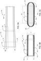
- FIG. 3A a portion of the spar 110 is shown.
- the location of the root seal 120 is shown with dashed lines.
- Section view A-A is shown in FIG. 3B and section view B-B is shown in FIG. 3C .
- the inboard portion 122 of the spar 110 has a roughly elliptical (e.g., oval) cross section that includes a top layer 132, a bottom layer 134, a leading edge conic 136, and a trailing edge conic 138.
- the top layer 132 includes an upper surface 133
- the bottom layer 134 includes a lower surface 135.
- the upper surface 133 and the lower surface 135 are substantially parallel.
- the upper surface 133 and lower surface of the inboard portion 122 of the spar 110 are spaced apart by a height H, which is substantially constant throughout the inboard portion 122.
- the thickness T1 of the top layer 132 is substantially constant throughout the inboard portion 122 of the spar 110.
- the thickness T2 of the bottom layer 134 is also substantially constant throughout the inboard portion 122 of the spar 110.
- the thickness T1 may be equal to the thickness T2, while in other embodiments, the thickness T1 may be different than the thickness T2. Because the height H and the thicknesses T1 and T2 do not vary throughout the inboard portion 122 of the spar 110, the spar 110 can be trimmed to various lengths, leaving a substantially flat inboard end to which a cuff can be easily coupled.
- the leading edge conic 136 and the trailing edge conic 138 begin where the upper and lower surfaces 133, 135 transition into the curved portion.
- the width W1 of the upper and lower surfaces 133, 135 may also be substantially constant throughout the inboard portion 122 of the spar 110.
- the width W2 of the leading edge conic 136 and the width W3 of the trailing edge conic 138 may increase moving inboard, such that the overall chordwise width of the spar 110 is largest (e.g., at a maximum) at the blade root 104 that the overall chordwise width of the spar 110 at locations further outboard.
- the chordwise width of the inboard portion 122 of the spar 110 may taper from a maximum width at the blade root 104 to a smaller width as the spar 110 extends outwardly from the blade root.
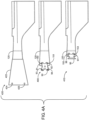
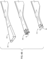
- FIGS. 4A and 4B illustrate two of multiple ways that the rotor blade 100 may be converted from a first configuration 400 for use on a first aircraft to a second configuration 410 for use on a second aircraft or a third configuration 420 for use on a second aircraft.
- FIG. 4A shows a plan view of each configuration 400, 410, 420
- FIG 4B shows a perspective view of each configuration 400, 410, 420. The position of the root seal 120 in each configuration 400, 410, 420 is shown in FIG. 4A .
- the rotor blade 100 is shown in a first configuration 400 (e.g., a base configuration) suitable for use in a first model of aircraft. This is the configuration shown in FIG. 2 .
- the base configuration 400 of the rotor blade 100 may include the attachment cuff 90 coupled to the mounting holes 150, 151, which extend through both the top and bottom layers 132, 132 of the spar 110. Pins or fasteners may be inserted into the mounting holes 150, 151 and the corresponding holes 91, 92 in the cuff 90 to couple the cuff 90 to the spar 110. In some embodiments, there may be more or fewer than two mounting holes. In other embodiments, the base configuration may not include a cuff and the cuff 90 may be provided separately.
- the cuff 90 includes one or more mounting holes 93, 94 configured to receive a pin or fastener that couples the cuff to corresponding holes in the rotor hub to couple the rotor blade 100 to the rotor hub.
- the rotor blade 100 may be adaptable for use in a second aircraft that requires a rotor blade with a shorter overall spanwise length.
- the rotor blade 100 is shown in FIGS. 4A and 4B in a second configuration 410 with a shortened spar 110.
- a method 500 of modifying a rotor blade e.g., rotor blade 100
- the rotor blade 100 may be converted from the first configuration 400 to the second configuration 410.
- a rotor blade is provided.
- the rotor blade 100 includes a spar having an inboard portion with a substantially constant overall height.
- the inboard portion further includes a top layer having a substantially constant first thickness and a bottom layer having substantially constant second thickness.
- the first thickness may be substantially equal to the second thickness.
- the rotor blade 100 may include a cutout 130 that may be required when the rotor blade is used on the second aircraft, but may not be required when the rotor blade 100 is used on the first aircraft.
- the second aircraft may include a rotor hub with a hinge configured to allow the rotor blade 100 to be folded (e.g., rotated, angled etc.) approximately about the rotor shaft axis (e.g., axis of rotation A) such that each rotor blade extends from the rotor hub 80 toward the aft end (e.g., the tail 16) of the second aircraft when the second aircraft is not in flight.
- the rotor blades 100 may be folded forward, or some blades 100 may be folded forward while others are folded rearward. This allows the second aircraft to have a more compact footprint for ground and water transportation, to be parked more closely to other objects or aircraft, and to fit more easily into cargo holds.
- the cutout 130 may be required such that the rotor blade does not contact other components of the second aircraft when folded.
- the first aircraft may not include such functionality.
- the cuff 90 is removed from the rotor blade 100.
- the pins may be removed from the mounting holes 150, 151, and the cuff 90 can be slid out from the blade root 104 of the rotor blade 100.
- the cuff 90 may be reused on another rotor blade or recycled.
- the base configuration of the rotor blade 100 does not include a cuff 90. Operation 504 may therefore be omitted and may not be required to complete the method 500 in some embodiments.
- the spar 110 is trimmed to a desired length.
- a root portion of the inboard portion 122 of the spar 110 can be removed to shorten the overall length of the rotor blade 100, so that the rotor blade 100 can be used on an aircraft model that requires a shorter rotor blade.
- the spar 110 may be trimmed by a water jet cutter or a CNC machining operation. However, other trimming methods are also contemplated.
- the root portion of the inboard portion 122 of the spar 110 that is removed in operation 506 may be entirely inboard of the root seal 120 positioned in the inner cavity of the spar 110.
- new mounting holes 152, 153 are formed in the spar 110.
- the new mounting holes 152, 153 may be drilled and reamed using a CNC machine.
- other methods of forming the holes are also contemplated.
- the root seal 120 may be positioned outboard of the location of the new mounting holes 152, 153 in the base configuration 400, so that a new root seal does not need to be installed after the spar 110 is trimmed. In some embodiments, there may be more or fewer than two mounting holes.
- a new cuff 95 is mounted to the new mounting holes 152, 153, thus converting the first configuration 400 of the rotor blade 100 to the second configuration 410.
- Pins or fasteners may be inserted into the new mounting holes 152, 153 and corresponding holes 96, 97 in the new cuff 95 to couple the new cuff 95 to the spar 110.
- the new cuff 95 may then be used to couple the trimmed rotor blade 100 to a rotor hub of the second aircraft.
- a pin or a fastener may be inserted into each of the one or more holes 96 and corresponding holes in the rotor hub to couple the rotor blade 100 to the rotor hub. In some embodiments, there may be more or fewer than two holes.
- the rotor blade 100 may be adaptable for use in a third aircraft that requires a rotor blade with a longer overall spanwise length.
- the rotor blade 100 is shown in FIG. 4 in a third configuration 420 with a blade extender 422.
- a method 600 of modifying a rotor blade e.g., rotor blade 100
- the rotor blade 100 may be converted from the first configuration 400 to the third configuration 420.
- a rotor blade is provided.
- the rotor blade includes a spar having an inboard portion with a substantially constant overall height.
- the inboard portion further includes a top layer having a substantially constant first thickness and a bottom layer having substantially constant second thickness.
- the first thickness may be substantially equal to the second thickness.
- the cuff 90 is removed from the rotor blade 100.
- the pins may be removed from the mounting holes 150, 151, and the cuff 90 can be slid out from the blade root 104 of the rotor blade 100.
- the cuff 90 may be reused on another rotor blade or recycled.
- the base configuration of the rotor blade 100 does not include a cuff 90. Operation 604 may therefore be omitted and may not be required to complete the method 600 in some embodiments.
- the blade extender 422 is coupled to the spar 110.
- the blade extender 422 is configured to couple the rotor blade to a third aircraft.
- the blade extender 422 may be coupled to the mounting holes 150, 151 to which the cuff 90 was previously coupled.
- pins or fasteners may be inserted into the mounting holes 150, 151 through corresponding holes in the blade extender 422 to couple the blade extender 422 to the spar 110.
- the blade extender 422 may fit around the spar 110 with the outboard end of the blade extender tapering to an opening that is smaller than the blade root 104 of the rotor blade 100.
- one or more coupler plates may couple the blade extender 422 to the mounting holes 150, 151.
- a first end of the coupler plate may be coupled to a mounting whole in the spar 110, and a second end of the coupler plate may be coupled to the blade extender.
- the blade extender 422 may then be used to couple the extended rotor blade 100 to a hub of the third aircraft.
- pins or fasteners may be inserted into the mounting holes 424, 425 and corresponding holes in the rotor hub to couple the rotor blade 100 to the rotor hub.
- the portion of the blade extender 422 that couples to the spar 110 may be referred to as a cuff or a cuff portion.
- the portion of blade encompassing the inboardmost portion of the spar 110 that has not been removed may be referred to as the "root end.”
- the location of the root end may vary based on whether and where the inboard portion 122 of the spar 110 is trimmed.
- the location of the blade root 104 may vary based vary based on whether and where the inboard portion 122 of the spar 110 is trimmed.
- Coupled means the joining of two members directly or indirectly to one another. Such joining may be stationary (e.g., permanent or fixed) or moveable (e.g., removable or releasable). Such joining may be achieved with the two members coupled directly to each other, with the two members coupled to each other using a separate intervening member and any additional intermediate members coupled with one another, or with the two members coupled to each other using an intervening member that is integrally formed as a single unitary body with one of the two members.
- Coupled or variations thereof are modified by an additional term (e.g., directly coupled)
- the generic definition of “coupled” provided above is modified by the plain language meaning of the additional term (e.g., "directly coupled” means the joining of two members without any separate intervening member), resulting in a narrower definition than the generic definition of "coupled” provided above.
- Such coupling may be mechanical, electrical, or fluidic.
Landscapes
- Engineering & Computer Science (AREA)
- Mechanical Engineering (AREA)
- Aviation & Aerospace Engineering (AREA)
- Structures Of Non-Positive Displacement Pumps (AREA)
- Turbine Rotor Nozzle Sealing (AREA)
Abstract
Description
- Rotary wing aircraft, such as helicopters, require different rotor blades depending on the model of the aircraft. Manufacturing the different rotor blades requires expensive custom tooling and machinery.
- The present disclosure related to the invention describes a rotor blade configured to be modified for use in a variety of rotary wing aircraft and methods of modifying the rotor blade.
- In an exemplary aspect, a method of modifying a rotor blade is provided. The rotor blade includes a spar having an inboard portion with a substantially constant overall height, the inboard portion further including a top layer having a substantially constant first thickness and a bottom layer having a substantially constant second thickness. The method includes adjusting a root portion of the inboard portion to thereby alter a length of the rotor blade from a first length to a second length and installing a cuff configured to couple to the rotor blade to an aircraft.
- According to an embodiment, adjusting the root portion comprises removing the root portion of the inboard portion to shorten the length of the rotor blade.
- According to an embodiment, the cuff is a second cuff and the aircraft is a second aircraft. The method further comprises removing a first cuff which is an original cuff from the rotor blade, the original cuff configured to couple the rotor blade to a first aircraft to which the first cuff is configured to couple the rotor blade.
- According to an embodiment, the rotor blade further comprises a root seal positioned in an inner cavity of the inboard portion, wherein the root portion is entirely inboard of the root seal.
- According to an embodiment, installing the cuff further comprises forming a cuff mounting hole in the spar and inserting a pin or a fastener though the cuff mounting hole and a corresponding hole in the cuff.
- According to an embodiment, the cuff mounting hole is formed inboard of the root seal.
- According to an embodiment, adjusting the root portion and installing the cuff comprises coupling a blade extender to the root portion of the spar, the blade extender comprising the cuff and configured to couple to the rotor blade to an aircraft.
- According to an embodiment, the method further comprises removing an original cuff from the rotor blade, the original cuff configured to couple the rotor blade to the first aircraft.
- According to an embodiment, removing the original cuff from the rotor blade comprises removing a pin that couples the original cuff to a mounting hole in the spar.
- According to an embodiment, coupling the blade extender to the root end of the spar comprises inserting a pin or fastener into the mounting hole and a corresponding hole in the blade extender.
- According to an embodiment, coupling the blade extender to the root end of the spar comprises coupling a first end of a coupler plate to the mounting hole and coupling a second end of the coupler plate to the blade extender.
- According to an embodiment, coupling the blade extender to the root end of the spar comprises positioning the blade extender around a blade root of the rotor blade, wherein an inboard end of the blade extender comprises an opening that is smaller than the blade root of the rotor blade.
- In another exemplary aspect, a rotor blade configured to be installed on a rotary wing aircraft incudes an inboard portion extending from a root of the rotor blade to a first spanwise position of the rotor blade, an outboard portion meeting the inboard portion at the first spanwise position, and an upper skin and a lower skin coupled the outboard portion of the spar. The first spanwise position is defined by a most inboard point at which the upper and lower skins are coupled to the spar. The inboard portion comprises a top layer, a bottom layer, and an inner cavity, wherein the top layer has a substantially constant first thickness and the bottom layer has a substantially constant second thickness, and wherein the distance between an outer surface of the top layer and an outer surface of the bottom layer is substantially constant.
- In yet another exemplary aspect, a rotor blade configured to be installed on a rotary wing aircraft is provided. The rotor blade includes a spar including an inboard portion extending from a root of the rotor blade to a first spanwise position of the rotor blade, an outboard portion meeting the inboard portion at the first spanwise position, and an upper skin and a lower skin coupled to the outboard portion of the spar. The first spanwise position is defined by a most inboard point at which the upper and lower skins are coupled to the spar. The inboard portion comprises a top layer, a bottom layer, and an inner cavity, wherein the top layer has a substantially constant first thickness and the bottom layer has a substantially constant second thickness, and wherein the distance between an outer surface of the top layer and an outer surface of the bottom layer is substantially constant.
- According to an embodiment of a rotor blade as described herein, the rotor blade further comprises a root seal positioned in the inner cavity of the inboard portion of the spar, wherein the root seal is positioned closer to the first spanwise position than to the root of the rotor blade.
- According to an embodiment of a rotor blade as described herein, the first thickness is substantially the same as the second thickness.
- According to an embodiment of a rotor blade as described herein, a chordwise width of the spar is at a maximum at the root of the rotor blade.
- According to an embodiment of a rotor blade as described herein, the chordwise width of the inboard portion of the spar tapers from the maximum to a smaller width as the spar extends outwardly from the root of the rotor blade.
- According to an embodiment of a rotor blade as described herein, a chordwise width of the outer surface of the top layer and the outer surface of the bottom layer is substantially constant throughout the inboard portion of the spar, wherein at least one of a chordwise width of a leading edge conic or a chordwise width of a trailing edge conic vary in the inboard portion of the spar.
- According to an embodiment of a rotor blade as described herein, the rotor blade further comprises a cuff and a mounting hole proximate the root of the rotor blade, the mounting hole configured to receive a pin to couple the rotor blade to the cuff.
- According to an embodiment of a rotor blade as described herein, the rotor blade further comprises a blade extender coupled to the root end of the spar, the blade extender configured to couple to the rotor blade to the aircraft.
-
-
FIG. 1 is a perspective view of a rotary wing aircraft. -
FIG. 2 is a perspective view of a rotor blade coupled to a rotor hub, according to some embodiments. -
FIG. 3A is a plan view of a portion of the spar of a rotor blade, according to some embodiments. -
FIG. 3B is a section view of the spar ofFIG. 3A . -
FIG. 3C is a section view of the spar ofFIG. 3A . -
FIG. 4A is a plan view of three configurations of a rotor blade, according to some embodiments. -
FIG. 4B is a perspective view of the three configurations ofFIG 4A . -
FIG. 5 is a flowchart illustrating a process of modifying a rotor blade, according to some embodiments. -
FIG. 6 is a flowchart illustrating a process of modifying a rotor blade, according to some embodiments. - It will be recognized that the Figures are the schematic representations for purposes of illustration. The Figures are provided for the purpose of illustrating one or more implementations with the explicit understanding that the Figures will not be used to limit the scope of the meaning of the claims.
- Following below are more detailed descriptions of various concepts related to, and implementations of, commonly manufactured rotor blades and method of modifying the blades for use in different models of aircraft. The various concepts introduced above and discussed in greater detail below may be implemented in any of a number of ways, as the described concepts are not limited to any particular manner of implementation. Examples of specific implementations and applications are provided primarily for illustrative purposes.
- Various models of rotary wing aircraft require similar, but distinct rotor blade designs. Custom manufacturing of each design occupies valuable factory floor space and requires custom tooling and machinery. Accordingly, it would be advantageous to provide single a rotor blade that can be easily adapted for use in multiple models of aircraft.
- The exemplary non-limiting embodiments described herein provide a rotor blade with a spar having an inboard end that has a substantially constant overall height, as well as a top and a bottom layer each having a substantially constant thickness. The inboard end of the spar can be trimmed for use in aircraft requiring a shorter overall spanwise blade length, or a blade extender can be coupled to the root end of the spar for use in an aircraft requiring a longer overall spanwise blade length. The blade root seal is positioned outboard of the outboardmost trim position, so that the root seal is not removed during the trimming process.
- Referring to
FIG. 1 , an example of a vertical takeoff and landing (VTOL) rotary-wing aircraft 10 having amain rotor system 12, such as a helicopter, is illustrated. As shown, theaircraft 10 includes anairframe 14 having an extendingtail 16, which mounts atail rotor system 18, such as an anti-torque system. Themain rotor system 12 is driven about an axis of rotation A via a main gearbox, illustrated schematically at T, by one or more engines, illustrated at E1-E3. Themain rotor system 12 includes a plurality ofrotor blades 20 mounted to a rotor hub assembly H. Therotor blades 20 may be rotor blades in accordance with the embodiments described herein. Although a particular helicopter configuration is illustrated and described herein, other configurations and/or aircraft may be utilized in connection with the concepts described herein. For example, the techniques according to the present disclosure may be implemented in a variety of aircraft, including a high speed compound rotary wing aircraft with supplemental translational thrust systems, a dual contra-rotating rotary aircraft, coaxial rotor system aircraft, a tilt-rotor aircraft, and a tilt-wing aircraft. - Referring to
FIG. 2 arotor blade 100 is shown, in accordance with an exemplary embodiment. Therotor blade 100 includes aninboard portion 102, including ablade root 104 defining the inboardmost end of therotor blade 100, and anoutboard portion 106, including ablade tip 108 defining the outboardmost end of therotor blade 100. Acuff 90 couples therotor blade 100 to therotor hub 80. Aspar 110 extends from theblade root 104 to an outboard end 116 in theoutboard portion 106 of therotor blade 100. Thespar 110 has aninboard portion 122 and anoutboard portion 126. Thespar 110 is the primary structural member of therotor blade 100. Anupper blade skin 112 and a lower blade skin 114 (on reverse side, not shown), as well as a leading edge sheath 115, are coupled to thespar 110 and define the aerodynamic surfaces of the airfoil. Theupper blade skin 112 and the lower blade skin 114 extend from aninboard end 118 of the blade skins 112, 114 toward theblade tip 108. Theinboard portion 122 of thespar 110 may be substantially the same as theinboard portion 102 of therotor blade 100, while theoutboard portion 106 of therotor blade 100 includes both theoutboard portion 126 of thespar 110 and the blade skins 112, 114. Theinboard end 118 of the blade skins 112, 114 may define a first spanwise position of thespar 110, at which theinboard portion 102 meets theoutboard portion 106 of thespar 110. - The blade skins 112, 114 may include a
cutout 130, rather than extending perpendicularly in the aft direction from the spar 110 (e.g., downward, as shown inFIG. 2 ). Thiscutout 130 may be required for certain models of aircraft, for example, aircraft models that are configured to fold the rotor blades rearward toward thetail 14 of theaircraft 10 or forward toward the nose in order to park the aircraft in a tight space. More specifically, therotor blade 100 may be coupled to a rotor hub that includes a hinge, and therotor blade 100 may be rotated rearward or forward about the hinge. When the rotor blades are folded back or forward, thecutout 130 is required to prevent therotor blade 100 from contacting other components of the aircraft. Though thecutout 130 may not be required for every aircraft model that therotor blade 100 is configured to be adapted to, thecutout 130 may be included such that therotor blade 100 can be used in models as applicable. Thecutout 130 may cause a minor decrease in performance of therotor blade 100; however, the cost savings expected from acommon rotor blade 100 used on several aircraft models may outweigh the minor decrease in performance, such that including thecutout 130 is justified. - The
spar 110 is exposed in theinboard portion 102 and is disposed between theupper blade skin 112, the lower blade skin 114, and the leading edge sheath 115 in theoutboard portion 106. Aroot seal 120 is positioned within an inner cavity of thespar 110 and is configured to keep water out of the portion of therotor blade 100 outboard of theroot seal 120. Theoutboard portion 106 of therotor blade 100 may be defined as the portion of therotor blade 100 that is outboard of theroot seal 120. Theroot seal 120 may be positioned more proximate to a first spanwise position defined by the inboard end of theblades skin 112, 114 than to theblade root 104. Theroot seal 120 is thus positioned further outboard than in conventional rotor blades. The positioning of theroot seal 120 allows a portion of theinboard portion 122 of thespar 110 to be trimmed. - Referring to
FIG. 3A , a portion of thespar 110 is shown. The location of theroot seal 120 is shown with dashed lines. Section view A-A is shown inFIG. 3B and section view B-B is shown inFIG. 3C . As shown inFIG. 3C , theinboard portion 122 of thespar 110 has a roughly elliptical (e.g., oval) cross section that includes atop layer 132, abottom layer 134, a leading edge conic 136, and a trailingedge conic 138. Thetop layer 132 includes anupper surface 133, and thebottom layer 134 includes alower surface 135. Theupper surface 133 and thelower surface 135 are substantially parallel. As shown inFIG. 3B , theupper surface 133 and lower surface of theinboard portion 122 of thespar 110 are spaced apart by a height H, which is substantially constant throughout theinboard portion 122. The thickness T1 of thetop layer 132 is substantially constant throughout theinboard portion 122 of thespar 110. The thickness T2 of thebottom layer 134 is also substantially constant throughout theinboard portion 122 of thespar 110. In some embodiments, the thickness T1 may be equal to the thickness T2, while in other embodiments, the thickness T1 may be different than the thickness T2. Because the height H and the thicknesses T1 and T2 do not vary throughout theinboard portion 122 of thespar 110, thespar 110 can be trimmed to various lengths, leaving a substantially flat inboard end to which a cuff can be easily coupled. - The leading edge conic 136 and the trailing edge conic 138 begin where the upper and
lower surfaces lower surfaces inboard portion 122 of thespar 110. The width W2 of the leading edge conic 136 and the width W3 of the trailing edge conic 138 may increase moving inboard, such that the overall chordwise width of thespar 110 is largest (e.g., at a maximum) at theblade root 104 that the overall chordwise width of thespar 110 at locations further outboard. The chordwise width of theinboard portion 122 of thespar 110 may taper from a maximum width at theblade root 104 to a smaller width as thespar 110 extends outwardly from the blade root. -
FIGS. 4A and4B illustrate two of multiple ways that therotor blade 100 may be converted from afirst configuration 400 for use on a first aircraft to asecond configuration 410 for use on a second aircraft or athird configuration 420 for use on a second aircraft.FIG. 4A shows a plan view of eachconfiguration FIG 4B shows a perspective view of eachconfiguration root seal 120 in eachconfiguration FIG. 4A . - The
rotor blade 100 is shown in a first configuration 400 (e.g., a base configuration) suitable for use in a first model of aircraft. This is the configuration shown inFIG. 2 . Thebase configuration 400 of therotor blade 100 may include theattachment cuff 90 coupled to the mountingholes bottom layers spar 110. Pins or fasteners may be inserted into the mountingholes holes cuff 90 to couple thecuff 90 to thespar 110. In some embodiments, there may be more or fewer than two mounting holes. In other embodiments, the base configuration may not include a cuff and thecuff 90 may be provided separately. Thecuff 90 includes one or more mountingholes rotor blade 100 to the rotor hub. - The
rotor blade 100 may be adaptable for use in a second aircraft that requires a rotor blade with a shorter overall spanwise length. Therotor blade 100 is shown inFIGS. 4A and4B in asecond configuration 410 with a shortenedspar 110. Referring toFIG. 5 (and with further reference toFIGS. 4A and4B ), amethod 500 of modifying a rotor blade (e.g., rotor blade 100), configured for use in a first aircraft, to be used in a second aircraft is shown, according to an exemplary embodiment. Using themethod 500, therotor blade 100 may be converted from thefirst configuration 400 to thesecond configuration 410. Atoperation 502 of themethod 500, a rotor blade is provided. Therotor blade 100 includes a spar having an inboard portion with a substantially constant overall height. The inboard portion further includes a top layer having a substantially constant first thickness and a bottom layer having substantially constant second thickness. In some embodiments, the first thickness may be substantially equal to the second thickness. Therotor blade 100 may include acutout 130 that may be required when the rotor blade is used on the second aircraft, but may not be required when therotor blade 100 is used on the first aircraft. For example, the second aircraft may include a rotor hub with a hinge configured to allow therotor blade 100 to be folded (e.g., rotated, angled etc.) approximately about the rotor shaft axis (e.g., axis of rotation A) such that each rotor blade extends from therotor hub 80 toward the aft end (e.g., the tail 16) of the second aircraft when the second aircraft is not in flight. In other examples, therotor blades 100 may be folded forward, or someblades 100 may be folded forward while others are folded rearward. This allows the second aircraft to have a more compact footprint for ground and water transportation, to be parked more closely to other objects or aircraft, and to fit more easily into cargo holds. Thecutout 130 may be required such that the rotor blade does not contact other components of the second aircraft when folded. The first aircraft may not include such functionality. - At
operation 504 of themethod 500, thecuff 90 is removed from therotor blade 100. For example, the pins may be removed from the mountingholes cuff 90 can be slid out from theblade root 104 of therotor blade 100. Thecuff 90 may be reused on another rotor blade or recycled. As discussed above, in some embodiments, the base configuration of therotor blade 100 does not include acuff 90.Operation 504 may therefore be omitted and may not be required to complete themethod 500 in some embodiments. - At
operation 506 of themethod 500, thespar 110 is trimmed to a desired length. For example, a root portion of theinboard portion 122 of thespar 110 can be removed to shorten the overall length of therotor blade 100, so that therotor blade 100 can be used on an aircraft model that requires a shorter rotor blade. In some embodiments, thespar 110 may be trimmed by a water jet cutter or a CNC machining operation. However, other trimming methods are also contemplated. The root portion of theinboard portion 122 of thespar 110 that is removed inoperation 506 may be entirely inboard of theroot seal 120 positioned in the inner cavity of thespar 110. Atoperation 508 of themethod 500, new mountingholes 152, 153 (e.g., cuff mounting holes) are formed in thespar 110. In some embodiments, the new mountingholes root seal 120 may be positioned outboard of the location of the new mountingholes base configuration 400, so that a new root seal does not need to be installed after thespar 110 is trimmed. In some embodiments, there may be more or fewer than two mounting holes. Atoperation 510 of themethod 500, anew cuff 95 is mounted to the new mountingholes first configuration 400 of therotor blade 100 to thesecond configuration 410. Pins or fasteners may be inserted into the new mountingholes corresponding holes new cuff 95 to couple thenew cuff 95 to thespar 110. Thenew cuff 95 may then be used to couple the trimmedrotor blade 100 to a rotor hub of the second aircraft. For example, a pin or a fastener may be inserted into each of the one ormore holes 96 and corresponding holes in the rotor hub to couple therotor blade 100 to the rotor hub. In some embodiments, there may be more or fewer than two holes. - Referring again to
FIGS. 4A and4B , therotor blade 100 may be adaptable for use in a third aircraft that requires a rotor blade with a longer overall spanwise length. Therotor blade 100 is shown inFIG. 4 in athird configuration 420 with ablade extender 422. Referring toFIG. 6 (and with further reference toFIG. 4 ), amethod 600 of modifying a rotor blade (e.g., rotor blade 100), configured for use in a first aircraft, to be used in a third aircraft is shown, according to an exemplary embodiment. Using themethod 500, therotor blade 100 may be converted from thefirst configuration 400 to thethird configuration 420. - At
operation 602 of themethod 600, a rotor blade is provided. The rotor blade includes a spar having an inboard portion with a substantially constant overall height. The inboard portion further includes a top layer having a substantially constant first thickness and a bottom layer having substantially constant second thickness. In some embodiments, the first thickness may be substantially equal to the second thickness. Atoperation 604 of themethod 600, thecuff 90 is removed from therotor blade 100. For example, the pins may be removed from the mountingholes cuff 90 can be slid out from theblade root 104 of therotor blade 100. Thecuff 90 may be reused on another rotor blade or recycled. As discussed above, in some embodiments, the base configuration of therotor blade 100 does not include acuff 90.Operation 604 may therefore be omitted and may not be required to complete themethod 600 in some embodiments. - At
operation 606 of themethod 600, theblade extender 422 is coupled to thespar 110. Theblade extender 422 is configured to couple the rotor blade to a third aircraft. In some embodiments, theblade extender 422 may be coupled to the mountingholes cuff 90 was previously coupled. For example, pins or fasteners may be inserted into the mountingholes blade extender 422 to couple theblade extender 422 to thespar 110. In some embodiments, there may be more or fewer than two mounting holes. In some embodiments, theblade extender 422 may fit around thespar 110 with the outboard end of the blade extender tapering to an opening that is smaller than theblade root 104 of therotor blade 100. In some embodiments, one or more coupler plates may couple theblade extender 422 to the mountingholes spar 110, and a second end of the coupler plate may be coupled to the blade extender. Theblade extender 422 may then be used to couple theextended rotor blade 100 to a hub of the third aircraft. For example, pins or fasteners may be inserted into the mountingholes rotor blade 100 to the rotor hub. In some embodiments, there may be more or fewer than two mounting holes. In some embodiments, the portion of theblade extender 422 that couples to thespar 110 may be referred to as a cuff or a cuff portion. - In each configuration, the portion of blade encompassing the inboardmost portion of the
spar 110 that has not been removed may be referred to as the "root end." The location of the root end may vary based on whether and where theinboard portion 122 of thespar 110 is trimmed. Similarly, the location of theblade root 104 may vary based vary based on whether and where theinboard portion 122 of thespar 110 is trimmed. - While this specification contains specific implementation details, these should not be construed as limitations on the scope of what may be claimed but rather as descriptions of features specific to particular implementations. Certain features described in this specification in the context of separate implementations can also be implemented in combination in a single implementation. Conversely, various features described in the context of a single implementation can also be implemented in multiple implementations separately or in any suitable subcombination. Moreover, although features may be described as acting in certain combinations and even initially claimed as such, one or more features from a claimed combination can, in some cases, be excised from the combination, and the claimed combination may be directed to a subcombination or variation of a subcombination.
- As utilized herein with respect to structural features (e.g., to describe shape, size, orientation, direction, relative position, etc.), the terms "approximately," "about," "substantially," and similar terms are meant to cover minor variations in structure that may result from, for example, the manufacturing or assembly process and are intended to have a broad meaning in harmony with the common and accepted usage by those of ordinary skill in the art to which the subject matter of this disclosure pertains. Accordingly, these terms should be interpreted as indicating that insubstantial or inconsequential modifications or alterations of the subject matter described and claimed are considered to be within the scope of the disclosure as recited in the appended claims.
- It should be noted that the term "exemplary" and variations thereof, as used herein to describe various embodiments, are intended to indicate that such embodiments are possible examples, representations, or illustrations of possible embodiments (and such terms are not intended to connote that such embodiments are necessarily extraordinary or superlative examples).
- The term "coupled" and variations thereof, as used herein, means the joining of two members directly or indirectly to one another. Such joining may be stationary (e.g., permanent or fixed) or moveable (e.g., removable or releasable). Such joining may be achieved with the two members coupled directly to each other, with the two members coupled to each other using a separate intervening member and any additional intermediate members coupled with one another, or with the two members coupled to each other using an intervening member that is integrally formed as a single unitary body with one of the two members. If "coupled" or variations thereof are modified by an additional term (e.g., directly coupled), the generic definition of "coupled" provided above is modified by the plain language meaning of the additional term (e.g., "directly coupled" means the joining of two members without any separate intervening member), resulting in a narrower definition than the generic definition of "coupled" provided above. Such coupling may be mechanical, electrical, or fluidic.
- References herein to the positions of elements (e.g., "top," "bottom," "above," "below") are merely used to describe the orientation of various elements in the FIGURES. It should be noted that the orientation of various elements may differ according to other exemplary embodiments, and that such variations are intended to be encompassed by the present disclosure.
- Although the figures and description may illustrate a specific order of method steps, the order of such steps may differ from what is depicted and described, unless specified differently above. Also, two or more steps may be performed concurrently or with partial concurrence, unless specified differently above.
Claims (15)
- A method of modifying a rotor blade, the rotor blade comprising a spar having an inboard portion with a substantially constant overall height, the inboard portion further including a top layer having a substantially constant first thickness and a bottom layer having a substantially constant second thickness, the method comprising:adjusting a root portion of the inboard portion to thereby alter a length of the rotor blade from a first length to a second length; andinstalling a cuff configured to couple the rotor blade to an aircraft.
- The method of claim 1, wherein adjusting the root portion comprises removing the root portion of the inboard portion to shorten the length of the rotor blade.
- The method of claim 1 or claim 2, wherein the cuff is a second cuff and the aircraft is a second aircraft, and the method further comprises removing a first cuff which is an original cuff from the rotor blade, the original cuff configured to couple the rotor blade to a first aircraft to which the first cuff is configured to couple the rotor blade.
- The method of any one of claims 1-3, wherein the rotor blade further comprises a root seal positioned in an inner cavity of the inboard portion, wherein the root portion is entirely inboard of the root seal.
- The method of claim 4, wherein installing the cuff further comprises forming a cuff mounting hole in the spar and inserting a pin or a fastener through the cuff mounting hole and a corresponding hole in the cuff, wherein the cuff mounting hole is formed inboard of the root seal.
- The method of any one of claims 1-5, further comprising removing an original cuff from the rotor blade, the original cuff configured to couple the rotor blade to a first aircraft, wherein adjusting the root portion and installing the cuff comprises coupling a blade extender to the root portion of the spar, the blade extender comprising the cuff and configured to couple the rotor blade to the aircraft.
- The method of claim 6, wherein removing the original cuff from the rotor blade comprises removing a pin that couples the original cuff to a mounting hole in the spar.
- The method of claim 7, wherein coupling the blade extender to the root portion of the spar comprises (a) inserting a pin or fastener into the mounting hole and a corresponding hole in the blade extender or (b) coupling a first end of a coupler plate to the mounting hole and coupling a second end of the coupler plate to the blade extender.
- The method of any one of claims 6-8, wherein coupling the blade extender to the root portion of the spar comprises positioning the blade extender around a blade root of the rotor blade, wherein an outboard end of the blade extender comprises an opening that is smaller than the blade root of the rotor blade.
- A rotor blade configured to be installed on a rotary wing aircraft, the rotor blade comprising:
a spar comprising:an inboard portion extending from a root of the rotor blade to a first spanwise position of the rotor blade;an outboard portion meeting the inboard portion at the first spanwise position; andan upper skin and a lower skin coupled the outboard portion of the spar,
wherein the first spanwise position is defined by a most inboard point at which the upper and lower skins are coupled to the spar,wherein the inboard portion comprises a top layer, a bottom layer, and an inner cavity, wherein the top layer has a substantially constant first thickness and the bottom layer has a substantially constant second thickness, and wherein a distance between an outer surface of the top layer and an outer surface of the bottom layer is substantially constant. - The rotor blade of claim 10, further comprising a root seal positioned in the inner cavity of the inboard portion of the spar, wherein the root seal is positioned closer to the first spanwise position than to the root of the rotor blade.
- The rotor blade of claim 10 or claim 11, wherein the first thickness is substantially the same as the second thickness.
- The rotor blade of any of claims 10-12, wherein a chordwise width of the spar is at a maximum at the root of the rotor blade.
- The rotor blade of claim 13, wherein the chordwise width of the inboard portion of the spar tapers from the maximum to a smaller width as the spar extends outwardly from the root of the rotor blade, wherein a chordwise width of the outer surface of the top layer and the outer surface of the bottom layer is substantially constant throughout the inboard portion of the spar, wherein at least one of a chordwise width of a leading edge conic or a chordwise width of a trailing edge conic vary in the inboard portion of the spar.
- The rotor blade of any of claims 10-14, further comprising (a) a cuff and a mounting hole proximate the root of the rotor blade, the mounting hole configured to receive a pin to couple the rotor blade to the cuff or (b) a blade extender coupled to a root portion of the spar, the blade extender configured to couple to the rotor blade to the rotary wing aircraft.
Priority Applications (1)
| Application Number | Priority Date | Filing Date | Title |
|---|---|---|---|
| EP24199775.8A EP4454874A3 (en) | 2022-08-04 | 2023-08-01 | Commonly manufactured rotor blade |
Applications Claiming Priority (1)
| Application Number | Priority Date | Filing Date | Title |
|---|---|---|---|
| US17/881,497 US11919627B2 (en) | 2022-08-04 | 2022-08-04 | Commonly manufactured rotor blade |
Related Child Applications (2)
| Application Number | Title | Priority Date | Filing Date |
|---|---|---|---|
| EP24199775.8A Division-Into EP4454874A3 (en) | 2022-08-04 | 2023-08-01 | Commonly manufactured rotor blade |
| EP24199775.8A Division EP4454874A3 (en) | 2022-08-04 | 2023-08-01 | Commonly manufactured rotor blade |
Publications (2)
| Publication Number | Publication Date |
|---|---|
| EP4316981A1 true EP4316981A1 (en) | 2024-02-07 |
| EP4316981B1 EP4316981B1 (en) | 2025-11-19 |
Family
ID=87553849
Family Applications (2)
| Application Number | Title | Priority Date | Filing Date |
|---|---|---|---|
| EP23188865.2A Active EP4316981B1 (en) | 2022-08-04 | 2023-08-01 | Commonly manufactured rotor blade |
| EP24199775.8A Pending EP4454874A3 (en) | 2022-08-04 | 2023-08-01 | Commonly manufactured rotor blade |
Family Applications After (1)
| Application Number | Title | Priority Date | Filing Date |
|---|---|---|---|
| EP24199775.8A Pending EP4454874A3 (en) | 2022-08-04 | 2023-08-01 | Commonly manufactured rotor blade |
Country Status (2)
| Country | Link |
|---|---|
| US (3) | US11919627B2 (en) |
| EP (2) | EP4316981B1 (en) |
Citations (6)
| Publication number | Priority date | Publication date | Assignee | Title |
|---|---|---|---|---|
| GB623322A (en) * | 1946-11-14 | 1949-05-16 | Sncan | Sustaining blade for rotating wing aircraft |
| GB831508A (en) * | 1956-12-03 | 1960-03-30 | United Aircraft Corp | Rotor blades for rotary wing aircraft |
| CA700992A (en) * | 1964-12-29 | Capowich George | Rotor blade sealing means | |
| US5417549A (en) * | 1994-03-11 | 1995-05-23 | United Technologies Corporation | Expandable spar filler block device |
| KR20120037195A (en) * | 2010-10-11 | 2012-04-19 | 유로캅터 도이칠란트 게엠베하 | Rotor blade made of a fibre-reinforced composite material and production method for it |
| US20200398968A1 (en) * | 2019-06-20 | 2020-12-24 | Tsc, Llc | Integrated Pultruded Composite Profiles and Method for Making Same |
Family Cites Families (14)
| Publication number | Priority date | Publication date | Assignee | Title |
|---|---|---|---|---|
| US2606728A (en) * | 1945-12-04 | 1952-08-12 | United Aircraft Corp | Rotor blade |
| US4169749A (en) * | 1977-09-21 | 1979-10-02 | The United States Of America As Represented By The Secretary Of The Navy | Method of making a hollow airfoil |
| US5263821A (en) * | 1991-01-15 | 1993-11-23 | United Technologies Corporation | Mid-beam jointed reconfigurable bearingless main rotor assembly |
| EP2246260B1 (en) * | 2009-04-29 | 2011-08-31 | EUROCOPTER DEUTSCHLAND GmbH | Rotor blade made of a fibre-reinforced composite material |
| US8662847B2 (en) * | 2010-10-11 | 2014-03-04 | Eurocopter Deutschland Gmbh | Rotor blade with control tube |
| US9169011B2 (en) * | 2011-09-13 | 2015-10-27 | Sikorsky Aircraft Corporation | Rotor with blades including outer blade shell and inner structural member |
| PT2626298E (en) * | 2012-02-09 | 2014-09-22 | Agustawestland Spa | Aircraft rotor blade and relative forming method |
| US9771152B2 (en) * | 2013-03-20 | 2017-09-26 | Sikorsky Aircraft Corporation | Flexbeam to rotor blade interface |
| US10793264B2 (en) * | 2014-06-27 | 2020-10-06 | Sikorsky Aircraft Corporation | Flex beam clamp for rotor assembly |
| US10654567B2 (en) * | 2015-03-26 | 2020-05-19 | Bell Helicopter Textron Inc. | Composite yoke fitting for bearing attachment to rotorcraft blade |
| US10227132B2 (en) * | 2015-08-04 | 2019-03-12 | Bell Helicopter Textron Inc. | Rotorcraft rotor blade assembly |
| US10696376B2 (en) * | 2016-04-05 | 2020-06-30 | Lanping JI | Foldable wing and rotocraft and glider using the same |
| US11014661B2 (en) * | 2016-10-24 | 2021-05-25 | Sikorsky Aircraft Corporation | Tip jet orifice for aircraft brown out mitigation |
| CA3085153C (en) * | 2017-12-14 | 2023-02-21 | Kawasaki Jukogyo Kabushiki Kaisha | Rotor craft including variable blade torsional angle mechanism |
-
2022
- 2022-08-04 US US17/881,497 patent/US11919627B2/en active Active
-
2023
- 2023-08-01 EP EP23188865.2A patent/EP4316981B1/en active Active
- 2023-08-01 EP EP24199775.8A patent/EP4454874A3/en active Pending
-
2024
- 2024-01-10 US US18/409,652 patent/US12252240B2/en active Active
-
2025
- 2025-02-25 US US19/063,108 patent/US12595048B2/en active Active
Patent Citations (6)
| Publication number | Priority date | Publication date | Assignee | Title |
|---|---|---|---|---|
| CA700992A (en) * | 1964-12-29 | Capowich George | Rotor blade sealing means | |
| GB623322A (en) * | 1946-11-14 | 1949-05-16 | Sncan | Sustaining blade for rotating wing aircraft |
| GB831508A (en) * | 1956-12-03 | 1960-03-30 | United Aircraft Corp | Rotor blades for rotary wing aircraft |
| US5417549A (en) * | 1994-03-11 | 1995-05-23 | United Technologies Corporation | Expandable spar filler block device |
| KR20120037195A (en) * | 2010-10-11 | 2012-04-19 | 유로캅터 도이칠란트 게엠베하 | Rotor blade made of a fibre-reinforced composite material and production method for it |
| US20200398968A1 (en) * | 2019-06-20 | 2020-12-24 | Tsc, Llc | Integrated Pultruded Composite Profiles and Method for Making Same |
Also Published As
| Publication number | Publication date |
|---|---|
| US20240140600A1 (en) | 2024-05-02 |
| US11919627B2 (en) | 2024-03-05 |
| US20250197000A1 (en) | 2025-06-19 |
| EP4316981B1 (en) | 2025-11-19 |
| US12595048B2 (en) | 2026-04-07 |
| EP4454874A3 (en) | 2024-12-25 |
| US20240043116A1 (en) | 2024-02-08 |
| US12252240B2 (en) | 2025-03-18 |
| EP4454874A2 (en) | 2024-10-30 |
Similar Documents
| Publication | Publication Date | Title |
|---|---|---|
| US8353673B2 (en) | Main rotor blade with integral cuff | |
| US7246998B2 (en) | Mission replaceable rotor blade tip section | |
| EP2229318B1 (en) | Main rotor blade with integral tip section | |
| US10183745B2 (en) | Tiltrotor with inboard engines | |
| EP3246248B1 (en) | Folding proprotor blade assembly having integral tang assembly | |
| EP3293110B1 (en) | Core material for balanced rotor blade | |
| EP2669187A2 (en) | Method of coupling aerofoil surface structures and an aerofoil assembly | |
| US20030222170A1 (en) | Derivative aircraft and methods for their manufacture | |
| EP3619108B1 (en) | Aircraft wing-to-fuselage interface permitting positional adjustment | |
| US11975832B2 (en) | Flow body for an aircraft having a solid trailing-edge component | |
| EP2976259B1 (en) | Flexbeam to rotor blade interface | |
| US11919627B2 (en) | Commonly manufactured rotor blade | |
| US11919620B2 (en) | Common spar assembly for use in nonfoldable and foldable proprotor blades | |
| EP3077284B1 (en) | Rotor shaft closeout plate | |
| EP2865878B1 (en) | Gimbal pin for jet propulsion system | |
| EP4640411A1 (en) | A method of manufacturing a fiber reinforced composite component | |
| US11433996B2 (en) | Lightweight low drag rotor pitch beam | |
| US12214872B2 (en) | Tip end joint arrangement for a rotor blade with reconfigurable attributes for structural and aerodynamic tuning | |
| EP4707165A1 (en) | Multipiece ribs for aircraft wing | |
| EP4223629B1 (en) | Resin pressure molded aerostructure with integrated metal coupling | |
| US20230266216A1 (en) | Apparatus for introducing test loads to a rotor blade | |
| EA051266B1 (en) | UNMANNED AERIAL VEHICLE AND METHOD OF ITS ASSEMBLY |
Legal Events
| Date | Code | Title | Description |
|---|---|---|---|
| PUAI | Public reference made under article 153(3) epc to a published international application that has entered the european phase |
Free format text: ORIGINAL CODE: 0009012 |
|
| STAA | Information on the status of an ep patent application or granted ep patent |
Free format text: STATUS: THE APPLICATION HAS BEEN PUBLISHED |
|
| AK | Designated contracting states |
Kind code of ref document: A1 Designated state(s): AL AT BE BG CH CY CZ DE DK EE ES FI FR GB GR HR HU IE IS IT LI LT LU LV MC ME MK MT NL NO PL PT RO RS SE SI SK SM TR |
|
| STAA | Information on the status of an ep patent application or granted ep patent |
Free format text: STATUS: REQUEST FOR EXAMINATION WAS MADE |
|
| 17P | Request for examination filed |
Effective date: 20240806 |
|
| RBV | Designated contracting states (corrected) |
Designated state(s): AL AT BE BG CH CY CZ DE DK EE ES FI FR GB GR HR HU IE IS IT LI LT LU LV MC ME MK MT NL NO PL PT RO RS SE SI SK SM TR |
|
| STAA | Information on the status of an ep patent application or granted ep patent |
Free format text: STATUS: EXAMINATION IS IN PROGRESS |
|
| 17Q | First examination report despatched |
Effective date: 20241105 |
|
| GRAP | Despatch of communication of intention to grant a patent |
Free format text: ORIGINAL CODE: EPIDOSNIGR1 |
|
| STAA | Information on the status of an ep patent application or granted ep patent |
Free format text: STATUS: GRANT OF PATENT IS INTENDED |
|
| INTG | Intention to grant announced |
Effective date: 20250801 |
|
| GRAS | Grant fee paid |
Free format text: ORIGINAL CODE: EPIDOSNIGR3 |
|
| GRAA | (expected) grant |
Free format text: ORIGINAL CODE: 0009210 |
|
| STAA | Information on the status of an ep patent application or granted ep patent |
Free format text: STATUS: THE PATENT HAS BEEN GRANTED |
|
| AK | Designated contracting states |
Kind code of ref document: B1 Designated state(s): AL AT BE BG CH CY CZ DE DK EE ES FI FR GB GR HR HU IE IS IT LI LT LU LV MC ME MK MT NL NO PL PT RO RS SE SI SK SM TR |
|
| REG | Reference to a national code |
Ref country code: CH Ref legal event code: F10 Free format text: ST27 STATUS EVENT CODE: U-0-0-F10-F00 (AS PROVIDED BY THE NATIONAL OFFICE) Effective date: 20251119 Ref country code: GB Ref legal event code: FG4D |
|
| REG | Reference to a national code |
Ref country code: DE Ref legal event code: R096 Ref document number: 602023008708 Country of ref document: DE |
|
| REG | Reference to a national code |
Ref country code: IE Ref legal event code: FG4D |
|
| REG | Reference to a national code |
Ref country code: NL Ref legal event code: MP Effective date: 20251119 |
|
| PG25 | Lapsed in a contracting state [announced via postgrant information from national office to epo] |
Ref country code: ES Free format text: LAPSE BECAUSE OF FAILURE TO SUBMIT A TRANSLATION OF THE DESCRIPTION OR TO PAY THE FEE WITHIN THE PRESCRIBED TIME-LIMIT Effective date: 20251119 |
|
| REG | Reference to a national code |
Ref country code: LT Ref legal event code: MG9D |
|
| PG25 | Lapsed in a contracting state [announced via postgrant information from national office to epo] |
Ref country code: NO Free format text: LAPSE BECAUSE OF FAILURE TO SUBMIT A TRANSLATION OF THE DESCRIPTION OR TO PAY THE FEE WITHIN THE PRESCRIBED TIME-LIMIT Effective date: 20260219 |
|
| PG25 | Lapsed in a contracting state [announced via postgrant information from national office to epo] |
Ref country code: HR Free format text: LAPSE BECAUSE OF FAILURE TO SUBMIT A TRANSLATION OF THE DESCRIPTION OR TO PAY THE FEE WITHIN THE PRESCRIBED TIME-LIMIT Effective date: 20251119 Ref country code: AT Free format text: LAPSE BECAUSE OF FAILURE TO SUBMIT A TRANSLATION OF THE DESCRIPTION OR TO PAY THE FEE WITHIN THE PRESCRIBED TIME-LIMIT Effective date: 20251119 Ref country code: FI Free format text: LAPSE BECAUSE OF FAILURE TO SUBMIT A TRANSLATION OF THE DESCRIPTION OR TO PAY THE FEE WITHIN THE PRESCRIBED TIME-LIMIT Effective date: 20251119 |
|
| REG | Reference to a national code |
Ref country code: AT Ref legal event code: MK05 Ref document number: 1858640 Country of ref document: AT Kind code of ref document: T Effective date: 20251119 |
|
| PG25 | Lapsed in a contracting state [announced via postgrant information from national office to epo] |
Ref country code: NL Free format text: LAPSE BECAUSE OF FAILURE TO SUBMIT A TRANSLATION OF THE DESCRIPTION OR TO PAY THE FEE WITHIN THE PRESCRIBED TIME-LIMIT Effective date: 20251119 |
|
| PG25 | Lapsed in a contracting state [announced via postgrant information from national office to epo] |
Ref country code: RS Free format text: LAPSE BECAUSE OF FAILURE TO SUBMIT A TRANSLATION OF THE DESCRIPTION OR TO PAY THE FEE WITHIN THE PRESCRIBED TIME-LIMIT Effective date: 20260219 |
|
| PG25 | Lapsed in a contracting state [announced via postgrant information from national office to epo] |
Ref country code: IS Free format text: LAPSE BECAUSE OF FAILURE TO SUBMIT A TRANSLATION OF THE DESCRIPTION OR TO PAY THE FEE WITHIN THE PRESCRIBED TIME-LIMIT Effective date: 20260319 |
|
| PG25 | Lapsed in a contracting state [announced via postgrant information from national office to epo] |
Ref country code: PT Free format text: LAPSE BECAUSE OF FAILURE TO SUBMIT A TRANSLATION OF THE DESCRIPTION OR TO PAY THE FEE WITHIN THE PRESCRIBED TIME-LIMIT Effective date: 20260319 |
|
| PG25 | Lapsed in a contracting state [announced via postgrant information from national office to epo] |
Ref country code: PL Free format text: LAPSE BECAUSE OF FAILURE TO SUBMIT A TRANSLATION OF THE DESCRIPTION OR TO PAY THE FEE WITHIN THE PRESCRIBED TIME-LIMIT Effective date: 20251119 |
|
| PG25 | Lapsed in a contracting state [announced via postgrant information from national office to epo] |
Ref country code: LV Free format text: LAPSE BECAUSE OF FAILURE TO SUBMIT A TRANSLATION OF THE DESCRIPTION OR TO PAY THE FEE WITHIN THE PRESCRIBED TIME-LIMIT Effective date: 20251119 |
|
| PG25 | Lapsed in a contracting state [announced via postgrant information from national office to epo] |
Ref country code: BG Free format text: LAPSE BECAUSE OF FAILURE TO SUBMIT A TRANSLATION OF THE DESCRIPTION OR TO PAY THE FEE WITHIN THE PRESCRIBED TIME-LIMIT Effective date: 20251119 |