EP4316969A1 - Gas treating system and ship - Google Patents
Gas treating system and ship Download PDFInfo
- Publication number
- EP4316969A1 EP4316969A1 EP22781298.9A EP22781298A EP4316969A1 EP 4316969 A1 EP4316969 A1 EP 4316969A1 EP 22781298 A EP22781298 A EP 22781298A EP 4316969 A1 EP4316969 A1 EP 4316969A1
- Authority
- EP
- European Patent Office
- Prior art keywords
- gas
- insulating space
- shell
- valve
- discharge passage
- Prior art date
- Legal status (The legal status is an assumption and is not a legal conclusion. Google has not performed a legal analysis and makes no representation as to the accuracy of the status listed.)
- Pending
Links
Images




Classifications
-
- B—PERFORMING OPERATIONS; TRANSPORTING
- B63—SHIPS OR OTHER WATERBORNE VESSELS; RELATED EQUIPMENT
- B63H—MARINE PROPULSION OR STEERING
- B63H21/00—Use of propulsion power plant or units on vessels
- B63H21/38—Apparatus or methods specially adapted for use on marine vessels, for handling power plant or unit liquids, e.g. lubricants, coolants, fuels or the like
-
- B—PERFORMING OPERATIONS; TRANSPORTING
- B63—SHIPS OR OTHER WATERBORNE VESSELS; RELATED EQUIPMENT
- B63B—SHIPS OR OTHER WATERBORNE VESSELS; EQUIPMENT FOR SHIPPING
- B63B11/00—Interior subdivision of hulls
- B63B11/04—Constructional features of bunkers, e.g. structural fuel tanks, or ballast tanks, e.g. with elastic walls
-
- B—PERFORMING OPERATIONS; TRANSPORTING
- B63—SHIPS OR OTHER WATERBORNE VESSELS; RELATED EQUIPMENT
- B63B—SHIPS OR OTHER WATERBORNE VESSELS; EQUIPMENT FOR SHIPPING
- B63B25/00—Load-accommodating arrangements, e.g. stowing, trimming; Vessels characterised thereby
- B63B25/02—Load-accommodating arrangements, e.g. stowing, trimming; Vessels characterised thereby for bulk goods
- B63B25/08—Load-accommodating arrangements, e.g. stowing, trimming; Vessels characterised thereby for bulk goods fluid
- B63B25/12—Load-accommodating arrangements, e.g. stowing, trimming; Vessels characterised thereby for bulk goods fluid closed
- B63B25/16—Load-accommodating arrangements, e.g. stowing, trimming; Vessels characterised thereby for bulk goods fluid closed heat-insulated
-
- F—MECHANICAL ENGINEERING; LIGHTING; HEATING; WEAPONS; BLASTING
- F02—COMBUSTION ENGINES; HOT-GAS OR COMBUSTION-PRODUCT ENGINE PLANTS
- F02M—SUPPLYING COMBUSTION ENGINES IN GENERAL WITH COMBUSTIBLE MIXTURES OR CONSTITUENTS THEREOF
- F02M21/00—Apparatus for supplying engines with non-liquid fuels, e.g. gaseous fuels stored in liquid form
- F02M21/02—Apparatus for supplying engines with non-liquid fuels, e.g. gaseous fuels stored in liquid form for gaseous fuels
- F02M21/0203—Apparatus for supplying engines with non-liquid fuels, e.g. gaseous fuels stored in liquid form for gaseous fuels characterised by the type of gaseous fuel
- F02M21/0209—Hydrocarbon fuels, e.g. methane or acetylene
-
- F—MECHANICAL ENGINEERING; LIGHTING; HEATING; WEAPONS; BLASTING
- F02—COMBUSTION ENGINES; HOT-GAS OR COMBUSTION-PRODUCT ENGINE PLANTS
- F02M—SUPPLYING COMBUSTION ENGINES IN GENERAL WITH COMBUSTIBLE MIXTURES OR CONSTITUENTS THEREOF
- F02M21/00—Apparatus for supplying engines with non-liquid fuels, e.g. gaseous fuels stored in liquid form
- F02M21/02—Apparatus for supplying engines with non-liquid fuels, e.g. gaseous fuels stored in liquid form for gaseous fuels
- F02M21/0218—Details on the gaseous fuel supply system, e.g. tanks, valves, pipes, pumps, rails, injectors or mixers
- F02M21/0245—High pressure fuel supply systems; Rails; Pumps; Arrangement of valves
-
- F—MECHANICAL ENGINEERING; LIGHTING; HEATING; WEAPONS; BLASTING
- F17—STORING OR DISTRIBUTING GASES OR LIQUIDS
- F17C—VESSELS FOR CONTAINING OR STORING COMPRESSED, LIQUEFIED OR SOLIDIFIED GASES; FIXED-CAPACITY GAS-HOLDERS; FILLING VESSELS WITH, OR DISCHARGING FROM VESSELS, COMPRESSED, LIQUEFIED, OR SOLIDIFIED GASES
- F17C13/00—Details of vessels or of the filling or discharging of vessels
- F17C13/04—Arrangement or mounting of valves
-
- F—MECHANICAL ENGINEERING; LIGHTING; HEATING; WEAPONS; BLASTING
- F17—STORING OR DISTRIBUTING GASES OR LIQUIDS
- F17C—VESSELS FOR CONTAINING OR STORING COMPRESSED, LIQUEFIED OR SOLIDIFIED GASES; FIXED-CAPACITY GAS-HOLDERS; FILLING VESSELS WITH, OR DISCHARGING FROM VESSELS, COMPRESSED, LIQUEFIED, OR SOLIDIFIED GASES
- F17C3/00—Vessels not under pressure
-
- F—MECHANICAL ENGINEERING; LIGHTING; HEATING; WEAPONS; BLASTING
- F17—STORING OR DISTRIBUTING GASES OR LIQUIDS
- F17C—VESSELS FOR CONTAINING OR STORING COMPRESSED, LIQUEFIED OR SOLIDIFIED GASES; FIXED-CAPACITY GAS-HOLDERS; FILLING VESSELS WITH, OR DISCHARGING FROM VESSELS, COMPRESSED, LIQUEFIED, OR SOLIDIFIED GASES
- F17C3/00—Vessels not under pressure
- F17C3/02—Vessels not under pressure with provision for thermal insulation
- F17C3/025—Bulk storage in barges or on ships
-
- F—MECHANICAL ENGINEERING; LIGHTING; HEATING; WEAPONS; BLASTING
- F17—STORING OR DISTRIBUTING GASES OR LIQUIDS
- F17C—VESSELS FOR CONTAINING OR STORING COMPRESSED, LIQUEFIED OR SOLIDIFIED GASES; FIXED-CAPACITY GAS-HOLDERS; FILLING VESSELS WITH, OR DISCHARGING FROM VESSELS, COMPRESSED, LIQUEFIED, OR SOLIDIFIED GASES
- F17C3/00—Vessels not under pressure
- F17C3/02—Vessels not under pressure with provision for thermal insulation
- F17C3/04—Vessels not under pressure with provision for thermal insulation by insulating layers
-
- F—MECHANICAL ENGINEERING; LIGHTING; HEATING; WEAPONS; BLASTING
- F17—STORING OR DISTRIBUTING GASES OR LIQUIDS
- F17C—VESSELS FOR CONTAINING OR STORING COMPRESSED, LIQUEFIED OR SOLIDIFIED GASES; FIXED-CAPACITY GAS-HOLDERS; FILLING VESSELS WITH, OR DISCHARGING FROM VESSELS, COMPRESSED, LIQUEFIED, OR SOLIDIFIED GASES
- F17C9/00—Methods or apparatus for discharging liquefied or solidified gases from vessels not under pressure
- F17C9/02—Methods or apparatus for discharging liquefied or solidified gases from vessels not under pressure with change of state, e.g. vaporisation
-
- B—PERFORMING OPERATIONS; TRANSPORTING
- B63—SHIPS OR OTHER WATERBORNE VESSELS; RELATED EQUIPMENT
- B63B—SHIPS OR OTHER WATERBORNE VESSELS; EQUIPMENT FOR SHIPPING
- B63B25/00—Load-accommodating arrangements, e.g. stowing, trimming; Vessels characterised thereby
- B63B25/02—Load-accommodating arrangements, e.g. stowing, trimming; Vessels characterised thereby for bulk goods
- B63B25/08—Load-accommodating arrangements, e.g. stowing, trimming; Vessels characterised thereby for bulk goods fluid
- B63B2025/087—Load-accommodating arrangements, e.g. stowing, trimming; Vessels characterised thereby for bulk goods fluid comprising self-contained tanks installed in the ship structure as separate units
-
- F—MECHANICAL ENGINEERING; LIGHTING; HEATING; WEAPONS; BLASTING
- F17—STORING OR DISTRIBUTING GASES OR LIQUIDS
- F17C—VESSELS FOR CONTAINING OR STORING COMPRESSED, LIQUEFIED OR SOLIDIFIED GASES; FIXED-CAPACITY GAS-HOLDERS; FILLING VESSELS WITH, OR DISCHARGING FROM VESSELS, COMPRESSED, LIQUEFIED, OR SOLIDIFIED GASES
- F17C2201/00—Vessel construction, in particular geometry, arrangement or size
- F17C2201/01—Shape
- F17C2201/0104—Shape cylindrical
-
- F—MECHANICAL ENGINEERING; LIGHTING; HEATING; WEAPONS; BLASTING
- F17—STORING OR DISTRIBUTING GASES OR LIQUIDS
- F17C—VESSELS FOR CONTAINING OR STORING COMPRESSED, LIQUEFIED OR SOLIDIFIED GASES; FIXED-CAPACITY GAS-HOLDERS; FILLING VESSELS WITH, OR DISCHARGING FROM VESSELS, COMPRESSED, LIQUEFIED, OR SOLIDIFIED GASES
- F17C2201/00—Vessel construction, in particular geometry, arrangement or size
- F17C2201/01—Shape
- F17C2201/0128—Shape spherical or elliptical
-
- F—MECHANICAL ENGINEERING; LIGHTING; HEATING; WEAPONS; BLASTING
- F17—STORING OR DISTRIBUTING GASES OR LIQUIDS
- F17C—VESSELS FOR CONTAINING OR STORING COMPRESSED, LIQUEFIED OR SOLIDIFIED GASES; FIXED-CAPACITY GAS-HOLDERS; FILLING VESSELS WITH, OR DISCHARGING FROM VESSELS, COMPRESSED, LIQUEFIED, OR SOLIDIFIED GASES
- F17C2201/00—Vessel construction, in particular geometry, arrangement or size
- F17C2201/01—Shape
- F17C2201/0147—Shape complex
- F17C2201/0157—Polygonal
-
- F—MECHANICAL ENGINEERING; LIGHTING; HEATING; WEAPONS; BLASTING
- F17—STORING OR DISTRIBUTING GASES OR LIQUIDS
- F17C—VESSELS FOR CONTAINING OR STORING COMPRESSED, LIQUEFIED OR SOLIDIFIED GASES; FIXED-CAPACITY GAS-HOLDERS; FILLING VESSELS WITH, OR DISCHARGING FROM VESSELS, COMPRESSED, LIQUEFIED, OR SOLIDIFIED GASES
- F17C2201/00—Vessel construction, in particular geometry, arrangement or size
- F17C2201/01—Shape
- F17C2201/0176—Shape variable
- F17C2201/0185—Shape variable with separating membrane
-
- F—MECHANICAL ENGINEERING; LIGHTING; HEATING; WEAPONS; BLASTING
- F17—STORING OR DISTRIBUTING GASES OR LIQUIDS
- F17C—VESSELS FOR CONTAINING OR STORING COMPRESSED, LIQUEFIED OR SOLIDIFIED GASES; FIXED-CAPACITY GAS-HOLDERS; FILLING VESSELS WITH, OR DISCHARGING FROM VESSELS, COMPRESSED, LIQUEFIED, OR SOLIDIFIED GASES
- F17C2201/00—Vessel construction, in particular geometry, arrangement or size
- F17C2201/03—Orientation
- F17C2201/035—Orientation with substantially horizontal main axis
-
- F—MECHANICAL ENGINEERING; LIGHTING; HEATING; WEAPONS; BLASTING
- F17—STORING OR DISTRIBUTING GASES OR LIQUIDS
- F17C—VESSELS FOR CONTAINING OR STORING COMPRESSED, LIQUEFIED OR SOLIDIFIED GASES; FIXED-CAPACITY GAS-HOLDERS; FILLING VESSELS WITH, OR DISCHARGING FROM VESSELS, COMPRESSED, LIQUEFIED, OR SOLIDIFIED GASES
- F17C2201/00—Vessel construction, in particular geometry, arrangement or size
- F17C2201/05—Size
- F17C2201/052—Size large (>1000 m3)
-
- F—MECHANICAL ENGINEERING; LIGHTING; HEATING; WEAPONS; BLASTING
- F17—STORING OR DISTRIBUTING GASES OR LIQUIDS
- F17C—VESSELS FOR CONTAINING OR STORING COMPRESSED, LIQUEFIED OR SOLIDIFIED GASES; FIXED-CAPACITY GAS-HOLDERS; FILLING VESSELS WITH, OR DISCHARGING FROM VESSELS, COMPRESSED, LIQUEFIED, OR SOLIDIFIED GASES
- F17C2201/00—Vessel construction, in particular geometry, arrangement or size
- F17C2201/05—Size
- F17C2201/054—Size medium (>1 m3)
-
- F—MECHANICAL ENGINEERING; LIGHTING; HEATING; WEAPONS; BLASTING
- F17—STORING OR DISTRIBUTING GASES OR LIQUIDS
- F17C—VESSELS FOR CONTAINING OR STORING COMPRESSED, LIQUEFIED OR SOLIDIFIED GASES; FIXED-CAPACITY GAS-HOLDERS; FILLING VESSELS WITH, OR DISCHARGING FROM VESSELS, COMPRESSED, LIQUEFIED, OR SOLIDIFIED GASES
- F17C2203/00—Vessel construction, in particular walls or details thereof
- F17C2203/03—Thermal insulations
- F17C2203/0304—Thermal insulations by solid means
- F17C2203/0337—Granular
- F17C2203/0341—Perlite
-
- F—MECHANICAL ENGINEERING; LIGHTING; HEATING; WEAPONS; BLASTING
- F17—STORING OR DISTRIBUTING GASES OR LIQUIDS
- F17C—VESSELS FOR CONTAINING OR STORING COMPRESSED, LIQUEFIED OR SOLIDIFIED GASES; FIXED-CAPACITY GAS-HOLDERS; FILLING VESSELS WITH, OR DISCHARGING FROM VESSELS, COMPRESSED, LIQUEFIED, OR SOLIDIFIED GASES
- F17C2203/00—Vessel construction, in particular walls or details thereof
- F17C2203/03—Thermal insulations
- F17C2203/0375—Thermal insulations by gas
-
- F—MECHANICAL ENGINEERING; LIGHTING; HEATING; WEAPONS; BLASTING
- F17—STORING OR DISTRIBUTING GASES OR LIQUIDS
- F17C—VESSELS FOR CONTAINING OR STORING COMPRESSED, LIQUEFIED OR SOLIDIFIED GASES; FIXED-CAPACITY GAS-HOLDERS; FILLING VESSELS WITH, OR DISCHARGING FROM VESSELS, COMPRESSED, LIQUEFIED, OR SOLIDIFIED GASES
- F17C2203/00—Vessel construction, in particular walls or details thereof
- F17C2203/06—Materials for walls or layers thereof; Properties or structures of walls or their materials
- F17C2203/0602—Wall structures; Special features thereof
- F17C2203/0612—Wall structures
- F17C2203/0626—Multiple walls
- F17C2203/0631—Three or more walls
-
- F—MECHANICAL ENGINEERING; LIGHTING; HEATING; WEAPONS; BLASTING
- F17—STORING OR DISTRIBUTING GASES OR LIQUIDS
- F17C—VESSELS FOR CONTAINING OR STORING COMPRESSED, LIQUEFIED OR SOLIDIFIED GASES; FIXED-CAPACITY GAS-HOLDERS; FILLING VESSELS WITH, OR DISCHARGING FROM VESSELS, COMPRESSED, LIQUEFIED, OR SOLIDIFIED GASES
- F17C2205/00—Vessel construction, in particular mounting arrangements, attachments or identifications means
- F17C2205/03—Fluid connections, filters, valves, closure means or other attachments
- F17C2205/0302—Fittings, valves, filters, or components in connection with the gas storage device
- F17C2205/0323—Valves
- F17C2205/0332—Safety valves or pressure relief valves
-
- F—MECHANICAL ENGINEERING; LIGHTING; HEATING; WEAPONS; BLASTING
- F17—STORING OR DISTRIBUTING GASES OR LIQUIDS
- F17C—VESSELS FOR CONTAINING OR STORING COMPRESSED, LIQUEFIED OR SOLIDIFIED GASES; FIXED-CAPACITY GAS-HOLDERS; FILLING VESSELS WITH, OR DISCHARGING FROM VESSELS, COMPRESSED, LIQUEFIED, OR SOLIDIFIED GASES
- F17C2205/00—Vessel construction, in particular mounting arrangements, attachments or identifications means
- F17C2205/03—Fluid connections, filters, valves, closure means or other attachments
- F17C2205/0302—Fittings, valves, filters, or components in connection with the gas storage device
- F17C2205/0341—Filters
-
- F—MECHANICAL ENGINEERING; LIGHTING; HEATING; WEAPONS; BLASTING
- F17—STORING OR DISTRIBUTING GASES OR LIQUIDS
- F17C—VESSELS FOR CONTAINING OR STORING COMPRESSED, LIQUEFIED OR SOLIDIFIED GASES; FIXED-CAPACITY GAS-HOLDERS; FILLING VESSELS WITH, OR DISCHARGING FROM VESSELS, COMPRESSED, LIQUEFIED, OR SOLIDIFIED GASES
- F17C2221/00—Handled fluid, in particular type of fluid
- F17C2221/01—Pure fluids
- F17C2221/012—Hydrogen
-
- F—MECHANICAL ENGINEERING; LIGHTING; HEATING; WEAPONS; BLASTING
- F17—STORING OR DISTRIBUTING GASES OR LIQUIDS
- F17C—VESSELS FOR CONTAINING OR STORING COMPRESSED, LIQUEFIED OR SOLIDIFIED GASES; FIXED-CAPACITY GAS-HOLDERS; FILLING VESSELS WITH, OR DISCHARGING FROM VESSELS, COMPRESSED, LIQUEFIED, OR SOLIDIFIED GASES
- F17C2221/00—Handled fluid, in particular type of fluid
- F17C2221/03—Mixtures
- F17C2221/032—Hydrocarbons
- F17C2221/033—Methane, e.g. natural gas, CNG, LNG, GNL, GNC, PLNG
-
- F—MECHANICAL ENGINEERING; LIGHTING; HEATING; WEAPONS; BLASTING
- F17—STORING OR DISTRIBUTING GASES OR LIQUIDS
- F17C—VESSELS FOR CONTAINING OR STORING COMPRESSED, LIQUEFIED OR SOLIDIFIED GASES; FIXED-CAPACITY GAS-HOLDERS; FILLING VESSELS WITH, OR DISCHARGING FROM VESSELS, COMPRESSED, LIQUEFIED, OR SOLIDIFIED GASES
- F17C2223/00—Handled fluid before transfer, i.e. state of fluid when stored in the vessel or before transfer from the vessel
- F17C2223/01—Handled fluid before transfer, i.e. state of fluid when stored in the vessel or before transfer from the vessel characterised by the phase
- F17C2223/0146—Two-phase
- F17C2223/0153—Liquefied gas, e.g. LPG, GPL
- F17C2223/0161—Liquefied gas, e.g. LPG, GPL cryogenic, e.g. LNG, GNL, PLNG
-
- F—MECHANICAL ENGINEERING; LIGHTING; HEATING; WEAPONS; BLASTING
- F17—STORING OR DISTRIBUTING GASES OR LIQUIDS
- F17C—VESSELS FOR CONTAINING OR STORING COMPRESSED, LIQUEFIED OR SOLIDIFIED GASES; FIXED-CAPACITY GAS-HOLDERS; FILLING VESSELS WITH, OR DISCHARGING FROM VESSELS, COMPRESSED, LIQUEFIED, OR SOLIDIFIED GASES
- F17C2223/00—Handled fluid before transfer, i.e. state of fluid when stored in the vessel or before transfer from the vessel
- F17C2223/03—Handled fluid before transfer, i.e. state of fluid when stored in the vessel or before transfer from the vessel characterised by the pressure level
- F17C2223/033—Small pressure, e.g. for liquefied gas
-
- F—MECHANICAL ENGINEERING; LIGHTING; HEATING; WEAPONS; BLASTING
- F17—STORING OR DISTRIBUTING GASES OR LIQUIDS
- F17C—VESSELS FOR CONTAINING OR STORING COMPRESSED, LIQUEFIED OR SOLIDIFIED GASES; FIXED-CAPACITY GAS-HOLDERS; FILLING VESSELS WITH, OR DISCHARGING FROM VESSELS, COMPRESSED, LIQUEFIED, OR SOLIDIFIED GASES
- F17C2250/00—Accessories; Control means; Indicating, measuring or monitoring of parameters
- F17C2250/03—Control means
- F17C2250/032—Control means using computers
-
- F—MECHANICAL ENGINEERING; LIGHTING; HEATING; WEAPONS; BLASTING
- F17—STORING OR DISTRIBUTING GASES OR LIQUIDS
- F17C—VESSELS FOR CONTAINING OR STORING COMPRESSED, LIQUEFIED OR SOLIDIFIED GASES; FIXED-CAPACITY GAS-HOLDERS; FILLING VESSELS WITH, OR DISCHARGING FROM VESSELS, COMPRESSED, LIQUEFIED, OR SOLIDIFIED GASES
- F17C2265/00—Effects achieved by gas storage or gas handling
- F17C2265/03—Treating the boil-off
- F17C2265/031—Treating the boil-off by discharge
-
- F—MECHANICAL ENGINEERING; LIGHTING; HEATING; WEAPONS; BLASTING
- F17—STORING OR DISTRIBUTING GASES OR LIQUIDS
- F17C—VESSELS FOR CONTAINING OR STORING COMPRESSED, LIQUEFIED OR SOLIDIFIED GASES; FIXED-CAPACITY GAS-HOLDERS; FILLING VESSELS WITH, OR DISCHARGING FROM VESSELS, COMPRESSED, LIQUEFIED, OR SOLIDIFIED GASES
- F17C2265/00—Effects achieved by gas storage or gas handling
- F17C2265/06—Fluid distribution
-
- F—MECHANICAL ENGINEERING; LIGHTING; HEATING; WEAPONS; BLASTING
- F17—STORING OR DISTRIBUTING GASES OR LIQUIDS
- F17C—VESSELS FOR CONTAINING OR STORING COMPRESSED, LIQUEFIED OR SOLIDIFIED GASES; FIXED-CAPACITY GAS-HOLDERS; FILLING VESSELS WITH, OR DISCHARGING FROM VESSELS, COMPRESSED, LIQUEFIED, OR SOLIDIFIED GASES
- F17C2270/00—Applications
- F17C2270/01—Applications for fluid transport or storage
- F17C2270/0102—Applications for fluid transport or storage on or in the water
- F17C2270/0105—Ships
-
- Y—GENERAL TAGGING OF NEW TECHNOLOGICAL DEVELOPMENTS; GENERAL TAGGING OF CROSS-SECTIONAL TECHNOLOGIES SPANNING OVER SEVERAL SECTIONS OF THE IPC; TECHNICAL SUBJECTS COVERED BY FORMER USPC CROSS-REFERENCE ART COLLECTIONS [XRACs] AND DIGESTS
- Y02—TECHNOLOGIES OR APPLICATIONS FOR MITIGATION OR ADAPTATION AGAINST CLIMATE CHANGE
- Y02T—CLIMATE CHANGE MITIGATION TECHNOLOGIES RELATED TO TRANSPORTATION
- Y02T70/00—Maritime or waterways transport
- Y02T70/50—Measures to reduce greenhouse gas emissions related to the propulsion system
- Y02T70/5218—Less carbon-intensive fuels, e.g. natural gas, biofuels
Definitions
- the present disclosure relates to a gas processing system and a ship including the gas processing system.
- a multiple-shell tank has been known, which includes: an inner shell storing a cryogenic liquid therein; and an outer shell accommodating the inner shell, a gas being filled in a space between the inner shell and the outer shell.
- PTL 1 discloses a double-shell tank including an inner shell and an outer shell. A space between the inner shell and the outer shell in the double-shell tank is filled with a boil off gas discharged from the inner shell. A discharge passage is connected to the outer shell such that the gas in the space between the inner shell and the outer shell can be discharged when pressure in the space is too high.
- the combustible gas When a combustible gas is filled in the space between the inner shell and the outer shell, and the combustible gas is discharged from the space between the inner shell and the outer shell as described above, the combustible gas needs to be safely processed. The same is true when the combustible gas is discharged from a space between two outer shells in a multiple-shell tank including three or more shells.
- An object of the present disclosure is to provide a gas processing system that can safely process a combustible gas discharged to an outside from a space located outside an inner shell of a multiple-shell tank, and a ship including the gas processing system.
- a gas processing system includes: a multiple-shell tank including an inner shell storing a cryogenic liquid therein, one or more outer shells accommodating the inner shell, a combustible gas being filled in an insulating space between the inner shell and the one or more outer shells or an insulating space between two adjacent outer shells among the outer shells; a combustor located outside the one or more outer shells; a discharge passage that discharges the combustible gas from the insulating space and guides the combustible gas to the combustor; and a discharge valve located at the discharge passage.
- a ship according to one aspect of the present disclosure includes the above gas processing system.
- the present disclosure can provide a gas processing system that can safely process a combustible gas discharged to an outside from a space located outside an inner shell in a multiple-shell tank, and a ship including the gas processing system.
- inside denotes a side closer to a center portion of a space in an inner shell of a multiple-shell tank
- the term “outside” denotes a side farther from the center portion of the space in the inner shell of the multiple-shell tank.
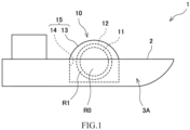
- FIG. 1 is a schematic side view of a ship 1 including a multiple-shell tank 10 according to Embodiment 1.
- the ship 1 is a liquefied gas carrier that carries a cryogenic liquid.
- the ship 1 includes the multiple-shell tank 10.
- the multiple-shell tank 10 includes an inner shell 11 and an outer shell 12 accommodating the inner shell 11.
- the cryogenic liquid is stored in a storage space R0 located inside the inner shell 11.
- a sealed insulating space R1 is located outside the inner shell 11 and inside the outer shell 12.
- Thermal insulation is located in the insulating space R1.
- the thermal insulation may be powder, such as perlite, or may be a heat preventing panel attached to a surface of the inner shell 11.
- each of the inner shell 11 and the outer shell 12 has a spherical shape.
- each of the inner shell 11 and the outer shell 12 does not necessarily have to have a spherical shape.
- each of the inner shell 11 and the outer shell 12 may have such a shape that a short tubular body is sandwiched between an upper hemispherical body and a lower hemispherical body, may have a laterally-placed cylindrical shape, or may have a rectangular shape.
- each of the inner shell 11 and the outer shell 12 may have such a shape as to bulge in a direction from a center of the inner shell 11 to an upper side at 45° and/or a direction from the center of the inner shell 11 to a lower side at 45°.
- the shape of the inner shell 11 and the shape of the outer shell 12 may be similar to each other or may not be similar to each other.
- the holding wall 14 is, for example, part of the hull 2.
- the holding wall 14 includes: a pair of longitudinal bulkheads that are located at both sides of the outer shell 12 in a ship width direction and extend in a ship longitudinal direction; an inner bottom plate that is located under the outer shell 12 and above a ship bottom outer plate of the hull 2 and extends in a ship longitudinal direction; and the like.
- the tank cover 13 and the holding wall 14 are configured as one accommodating structure 15 that accommodates the outer shell 12. Since the tank cover 13 and the holding wall 14 cover the outer shell 12, a sealed space is located inside the tank cover 13 and the holding wall 14 and outside the outer shell 12. In other words, the tank cover 13 and the holding wall 14 serve as one outer shell that further covers the outer shell 12.
- the outer shell of the multiple-shell tank also denotes a shell that serves as an outermost shell, such as the accommodating structure 15 including the tank cover and the holding wall, which forms a sealed space together with an inside outer shell.
- the multiple-shell tank 10 does not necessarily have to be mounted as a cargo tank on the ship 1 and may be mounted as a fuel tank. Moreover, although FIG. 1 shows the ship 1 including one multiple-shell tank 10, the ship 1 may include the multiple-shell tanks 10. When the ship 1 includes the multiple-shell tanks 10, a bulkhead located between two adjacent multiple-shell tanks 10 is also included in the accommodating structure 15 covering the outer shell 12.
- the ship 1 includes a gas processing system 3A that can process the combustible gas discharged from the insulating space R1 in the above case.
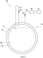
- FIG. 2 is a schematic configuration diagram showing an entire configuration of the gas processing system 3A shown in FIG. 1 .
- the gas processing system 3A includes the above-described multiple-shell tank 10.
- FIG. 2 shows a sectional view of the inner shell 11 and the outer shell 12.
- the tank cover 13 and the holding wall 14 are not shown.
- the inner shell 11 separates the storage space R0 and the insulating space R1.
- the storage space R0 is located inside the inner shell 11 and stores the cryogenic liquid.
- the insulating space R1 is located outside the inner shell 11 and inside the outer shell 12.
- a gas layer at an upper portion of the storage space R0 is filled with a boil off gas generated by vaporization of a cryogenic fluid in the storage space R0.
- the boil off gas in the storage space R0 is a combustible gas.
- the insulating space R1 is filled with a combustible gas that is the same in type as the boil off gas in the inner shell 11.
- the cryogenic liquid in the storage space R0 is liquefied hydrogen
- the gas in the insulating space R1 is a hydrogen gas.
- the multiple-shell tank 10 includes an introducing passage 21 through which the boil off gas in the inner shell 11, i.e., the boil off gas in the storage space R0 is introduced into the insulating space R1.
- An introducing valve 22 is located at the introducing passage 21.
- the introducing valve 22 is a valve that opens when the pressure in the insulating space R1 becomes lower than predetermined set lower limit pressure.
- the introducing valve 22 is a manual valve or remote control valve controlled by an operator.
- the gas processing system 3A may include a gas supplier that introduces a combustible gas into the insulating space R1 from the outside of the multiple-shell tank 10.
- the gas processing system 3A includes a combustor 31, a discharge passage 32, a discharge valve 33, and a filter 34.
- the combustor 31 is located outside the outer shell 12.
- One end portion of the discharge passage 32 is located in the insulating space R1, and the other end portion of the discharge passage 32 is connected to the combustor 31.
- the discharge passage 32 discharges the combustible gas from the insulating space R1 and guides the combustible gas to the combustor 31.
- the combustor 31 combusts the combustible gas which has been guided by the discharge passage 32.
- the discharge valve 33 is located at the discharge passage 32.
- the discharge valve 33 is a valve that releases the pressure in the insulating space R1 when the pressure in the insulating space R1 becomes the set upper limit pressure or more.
- the discharge valve 33 is a manual valve or remote control valve controlled by an operator or a self-operated automatic valve (safety valve, for example) that automatically opens when the pressure in the insulating space R1 becomes the set upper limit pressure or more.
- the pressure at the combustor 31 side in the discharge passage 32 is maintained lower than the pressure in the insulating space R1. Therefore, when the discharge valve 33 opens, the combustible gas is supplied from the insulating space R1 through the discharge passage 32 to the combustor 31 by the pressure of the gas in the insulating space R1.
- an exhauster may be located at the discharge passage 32, and the combustible gas may be forcibly supplied from the insulating space R1 to the combustor 31. Examples of the exhauster include a compressor and an exhaust pump. In this case, the pressure at the combustor 31 side in the discharge passage 32 does not have to be maintained lower than the pressure in the insulating space R1.
- the filter 34 is located at a portion of the discharge passage 32 which is located between the discharge valve 33 and the combustor 31.
- the filter 34 removes foreign matters in the combustible gas which has been guided from the insulating space R1.
- the foreign matters in the gas are assumed to be, for example, chips of the thermal insulation located in the insulating space R1 or dust in the gas which has entered into the insulating space R1 during construction.
- the combustible gas discharged from the insulating space R1 located outside the inner shell 11 in the multiple-shell tank 10 can be safely processed by being combusted by the combustor 31.
- the boil off gas in the inner shell 11 can be introduced into the insulating space R1 through the introducing passage 21. Therefore, a device that introduces a gas to the insulating space R1 does not have to be additionally prepared outside the multiple-shell tank 10.
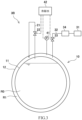
- FIG. 3 is a schematic configuration diagram showing an entire configuration of a gas processing system 3B according to Modified Example 1 of Embodiment 1.
- the gas processing system 3B includes a pressure gauge 41 and a controller 42.
- the pressure gauge 41 measures the pressure in the insulating space R1.
- the pressure gauge 41 is communicably connected to the controller 42. Information of the pressure measured by the pressure gauge 41 is sent to the controller 42.
- the introducing valve 22 and the discharge valve 33 are control valves controlled by the controller 42.
- the controller 42 is a so-called computer and includes: a calculation processor, such as a CPU; and a storage, such as a ROM and a RAM (not shown).
- the storage stores a program executed by the calculation processor, various fixed data, and the like.
- the calculation processor performs data transmission and reception with an external device.
- the controller 42 performs gas pressure adjustment processing of adjusting the pressure of the gas in the insulating space R1 in such a manner that the calculation processor reads and executes a predetermined gas pressure adjustment program stored in the storage.
- the controller 42 may include computers. In this case, the controller 42 may control the introducing valve 22 and the discharge valve 33 by distributed control performed by the cooperation of the computers or may individually control the introducing valve 22 and the discharge valve 33.
- the storage of the controller 42 stores the predetermined set upper limit pressure and the set lower limit pressure lower than the set upper limit pressure.
- the controller 42 may determine one or both of the set upper limit pressure and the set lower limit pressure in accordance with the pressure of the gas layer in the inner shell 11 and/or the temperature in the inner shell 11.
- the controller 42 controls the discharge valve 33 and the introducing valve 22 such that the pressure of the gas in the insulating space R1 is maintained within a range of not more than the set upper limit pressure and not less than the set lower limit pressure.
- the controller 42 controls the discharge valve 33 such that the discharge valve 33 opens when the pressure measured by the pressure gauge 41 exceeds the set upper limit pressure. Then, after the discharge valve 33 opens, for example, the controller 42 controls the discharge valve 33 such that the discharge valve 33 closes when the pressure measured by the pressure gauge 41 becomes lower than the set upper limit pressure or when the pressure measured by the pressure gauge 41 becomes lower than a predetermined first set value between the set upper limit pressure and the set lower limit pressure.
- the controller 42 controls the introducing valve 22 such that the introducing valve 22 opens when the pressure measured by the pressure gauge 41 falls below the set lower limit pressure. Then, after the introducing valve 22 opens, for example, the controller 42 controls the introducing valve 22 such that the introducing valve 22 closes when the pressure measured by the pressure gauge 41 becomes higher than the set lower limit pressure or when the pressure measured by the pressure gauge 41 becomes higher than a predetermined second set value between the set upper limit pressure and the set lower limit pressure.
- the pressure of the gas in the insulating space R1 is adjusted by the gas pressure adjustment program stored in the storage of the controller 42. Therefore, a range in which the pressure of the gas in the insulating space R1 is maintained is easily changed.
- both of the introducing valve 22 and the discharge valve 33 do not have to be controlled by the controller 30, and only one of the introducing valve 22 and the discharge valve 33 may be controlled by the controller 30.
- the controller 42 may control only one of the introducing valve 22 and the discharge valve 33.
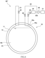
- FIG. 4 is a schematic configuration diagram showing an entire configuration of a gas processing system 3C according to Modified Example 2 of Embodiment 1.
- the gas processing system 3C further includes: an atmosphere open passage 43 through which the insulating space R1 is open to the atmosphere; and an atmosphere open valve 44 located at the atmosphere open passage 43.
- One end portion of the atmosphere open passage 43 is located in the insulating space R1, and the other end portion of the atmosphere open passage 43 is open to the atmosphere.
- the discharge valve 33 is a manual valve or remote control valve which is controlled by an operator to release the pressure in the insulating space R1.
- the atmosphere open valve 44 is an automatic valve that automatically releases the pressure in the insulating space R1 when the pressure in the insulating space R1 becomes the set upper limit pressure or more. Before the pressure in the insulating space R1 reaches the set upper limit pressure, the discharge valve 33 is controlled by an operator to open. Therefore, basically, the atmosphere open valve 44 does not open. However, there are cases, such as a case where the reduction in the pressure in the insulating space R1 is inadequate even though the combustible gas is being supplied from the insulating space R1 to the combustor 31 (for example, a case where the gas, the amount of which exceeds an allowable processing capacity, is supplied to the combustor 31) and a case where the combustor 31 is broken.
- the pressure in the insulating space R1 reaches the set upper limit pressure, and the atmosphere open valve 44 opens. Therefore, according to Modified Example 2, in an emergency in which the remaining combustible gas exists in the insulating space R1 although the combustible gas is being guided to the combustor 31, the remaining combustible gas can be discharged from the insulating space R1 through the atmosphere open passage 43 by opening the atmosphere open valve 44.
- the pressure of the gas in the insulating space R1 can be maintained within a pressure range that is allowable from the viewpoint of structural strengths of the inner shell 11 and the outer shell 12.
- the atmosphere open valve 44 may be a self-operated automatic valve (safety valve, for example). Or, for example, the atmosphere open valve 44 may be controlled by the controller 42 described in Modified Example 1.
- the atmosphere open passage 43 may extend so as to branch from a portion of the discharge passage 32.
- the gas processing system 3C may be able to select whether to supply the gas to the combustor 31 through the discharge passage 32 or to release the gas to the atmosphere through the atmosphere open passage 43.
- FIG. 5 is a schematic configuration diagram showing an entire configuration of a gas processing system 3D according to Modified Example 3 of Embodiment 1.
- the gas processing system 3D guides the combustible gas discharged from the insulating space R1 and the boil off gas of the gas layer in the storage space R0 to the same combustor 31.
- the gas processing system 3D includes the above-described multiple-shell tank 10, the introducing passage 21, the introducing valve 22, the combustor 31, the discharge passage 32, the discharge valve 33, and the filter 34. Moreover, the gas processing system 3D includes a BOG discharge passage 45 and a BOG discharge valve 46.
- One end portion 45a of the BOG discharge passage 45 is located at the gas layer in the storage space R0, and the other end portion of the BOG discharge passage 45 is connected to a portion of the discharge passage 32 which is located between the filter 34 and the combustor 31.
- the BOG discharge passage 45 discharges the boil off gas from the inside of the inner shell 11 and guides the boil off gas to the portion of the discharge passage 32 which is located between the filter 34 and the combustor 31.
- the other end portion of the BOG discharge passage 45 may be connected to the portion of the discharge passage 32 which is located between the discharge valve 33 and the filter 34.
- a portion of the discharge passage 32 to which the BOG discharge passage 45 is connected is referred to as a joining portion 32b.
- the BOG discharge valve 46 is located at the BOG discharge passage 45.
- the BOG discharge valve 46 is a valve that releases the pressure of the gas layer in the storage space R0 when the pressure of the gas layer in the storage space R0 becomes the set upper limit pressure or more.
- the BOG discharge valve 46 is a manual valve or remote control valve controlled by an operator or a self-operated automatic valve (safety valve, for example) that automatically opens when the pressure of the gas layer in the storage space R0 becomes the set upper limit pressure or more.
- a check valve 35 is located at a portion of the discharge passage 32 which is located between the discharge valve 33 and the joining portion 32b.
- the check valve 35 prevents the gas from flowing backward to the insulating space R1.
- a check valve 47 is located at a portion of the BOG discharge passage 45 which is located between the other end portion (i.e., the joining portion 32b) of the BOG discharge passage 45 and the BOG discharge valve 46. The check valve 47 prevents the gas from flowing backward to the gas layer in the storage space R0.
- the pressure at the combustor 31 side in the discharge passage 32 is maintained lower than each of the pressure in the insulating space R1 and the pressure of the gas layer in the storage space R0. Therefore, when the discharge valve 33 opens, the combustible gas is supplied from the insulating space R1 through the discharge passage 32 to the combustor 31 by the pressure of the gas in the insulating space R1. Moreover, when the BOG discharge valve 46 opens, the combustible gas is supplied from the gas layer in the storage space R0 through the BOG discharge passage 45 to the combustor 31 by the pressure of the gas in the gas layer in the storage space R0.
- an exhauster 48 may be located at a portion of the discharge passage 32 which is located between the joining portion 32b and the combustor 31, and the gas may be forcibly supplied from the insulating space R1 and the gas layer in the storage space R0 to the combustor 31.
- the exhausters 48 may be located at the BOG discharge passage 45 and a portion of the discharge passage 32 which is located between the joining portion 32b and the filter 34. In this case, the pressure at the combustor 31 side in the discharge passage 32 does not have to be maintained lower than each of the pressure in the insulating space R1 and the pressure of the gas layer in the storage space R0.
- Examples of the exhauster 48 include a compressor and an exhaust pump.
- Both the filter 34 and the exhauster 48 may be located at the portion of the discharge passage 32 which is located between the joining portion 32b and the combustor 31.
- the filter 34 is located at a portion of the discharge passage 32 which is located between the joining portion 32b and the exhauster 48. This is to prevent foreign matters in the combustible gas guided from the insulating space R1 from entering into the exhauster 48.
- the combustible gas discharged from the insulating space R1 located outside the inner shell 11 in the multiple-shell tank 10 and the boil off gas generated in the inner shell 11 can be safely processed by being combusted by the single combustor 31.
- the check valve 35 and the check valve 47 are respectively located at the discharge passage 32 and the BOG discharge passage 45. Therefore, when both the discharge valve 33 and the BOG discharge valve 46 open, the combustible gas can be prevented from flowing from one of the insulating space R1 and the gas layer in the storage space R0 to the other.
- the check valve 35 and the check valve 47 do not necessarily have to be respectively located at the discharge passage 32 and the BOG discharge passage 45.
- only one of the discharge valve 33 and the BOG discharge valve 46 may be operated or controlled so as to open.
- the exhauster 48 may be located at the portion of the discharge passage 32 which is located between the joining portion 32b and the combustor 31, and the gas may be forcibly supplied to the combustor 31.
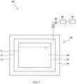
- FIG. 7 is a schematic configuration diagram showing an entire configuration of a gas processing system 4A according to Embodiment 2 of the present disclosure.
- FIG. 7 includes a sectional view of a multiple-shell tank 50 included in the gas processing system 4A.
- the multiple-shell tank 50 is a membrane tank mounted on a ship.
- the multiple-shell tank 50 includes: a primary membrane 51 storing a cryogenic liquid; a secondary membrane 52 covering the primary membrane 51; and a hull inner shell 53 further covering the secondary membrane 52.
- the hull inner shell 53 is part of the hull.
- the cryogenic liquid is stored in a storage space M0 in the primary membrane 51.
- a sealed first insulating space M1 (so-called inter barrier space (IBS)) is located between the primary membrane 51 and the secondary membrane 52. Thermal insulation is located in the first insulating space M1.
- a sealed second insulating space M2 is located between the secondary membrane 52 and the hull inner shell 53. Thermal insulation is located in the second insulating space M2 (so-called insulation space (IS)).
- Each of the primary membrane 51 and the secondary membrane 52 does not have such strength as to support the pressure and weight of the cryogenic liquid in the primary membrane 51.
- the pressure and weight of the cryogenic liquid in the primary membrane 51 are supported by the hull through the thermal insulation in the first insulating space M1 and the thermal insulation in the second insulating space M2.
- the primary membrane 51 has a sealing function that separates the storage space M0 and the first insulating space M1
- the secondary membrane 52 has a sealing function that separates the first insulating space M1 and the second insulating space M2.
- the primary membrane 51 serves as an inner shell storing the cryogenic liquid therein
- the secondary membrane 52 serves as an outer shell accommodating the primary membrane 51 serving as the inner shell
- the hull inner shell 53 serves as an outer shell further covering the secondary membrane 52 serving as the outer shell.
- the primary membrane 51, the secondary membrane 52, and the hull inner shell 53 are respectively referred to as an inner shell 51, a first outer shell 52, and a second outer shell 53.
- a gas layer located at an upper portion in the storage space M0 is filled with a boil off gas generated by evaporation of the cryogenic fluid in the storage space M0.
- the boil off gas in the storage space M0 is a combustible gas
- the first insulating space M1 and the second insulating space are also filled with a combustible gas.
- the storage space M0 stores liquefied hydrogen
- the first insulating space M1 is filled with a hydrogen gas.
- the second insulating space M2 is filled with a nitrogen gas or a hydrogen gas.
- the gas processing system 4A processes the combustible gas discharged from the first insulating space M1.
- the gas processing system 4A includes a combustor 61, a discharge passage 62, a discharge valve 63, and a filter 64.
- the combustor 61 is located outside the first outer shell 52 and the second outer shell 53.
- One end portion of the discharge passage 62 is located in the first insulating space M1, and the other end portion of the discharge passage 62 is connected to the combustor 61.
- the discharge passage 62 discharges the combustible gas from the first insulating space M1 and guides the combustible gas to the combustor 61.
- the discharge valve 63 is located at the discharge passage 62.
- the discharge valve 63 is a valve that releases the pressure in the first insulating space M1 when the pressure in the first insulating space M1 becomes the set upper limit pressure or more.
- the discharge valve 33 is a manual valve or remote control valve controlled by an operator or a self-operated automatic valve (safety valve, for example) that automatically opens when the pressure in the first insulating space M1 becomes the set upper limit pressure or more.
- the pressure at the combustor 61 side in the discharge passage 62 is maintained lower than the pressure in the first insulating space M1. Therefore, when the discharge valve 63 opens, the combustible gas is supplied from the first insulating space M1 through the discharge passage 62 to the combustor 61 by the pressure of the gas in the first insulating space M1.
- an exhauster may be located at the discharge passage 62, and the combustible gas may be forcibly supplied from the first insulating space M1 to the combustor 61. Examples of the exhauster include a compressor and an exhaust pump.
- the filter 64 is located at a portion of the discharge passage 62 which is located between the discharge valve 63 and the combustor 61.
- the filter 64 removes foreign matters in the combustible gas guided from the first insulating space M1.
- the foreign matters in the gas are assumed to be, for example, chips of the thermal insulation located in the first insulating space M1.
- the combustible gas discharged from the first insulating space M1 located outside the inner shell 51 in the multiple-shell tank 50 can be safely processed by being combusted by the combustor 61.
- FIG. 8 is a schematic configuration diagram showing an entire configuration of a gas processing system 4B according to Modified Example 1 of Embodiment 2.
- the gas processing system 4B processes the combustible gas discharged from the second insulating space M2.
- the second insulating space M2 is filled with a hydrogen gas.
- the gas processing system 4B includes a combustor 71, a discharge passage 72, a discharge valve 73, and a filter 74.
- an end portion of the discharge passage 72 is located in the second insulating space M2, not in the first insulating space M1.
- the combustor 71, the discharge passage 72, the discharge valve 73, and the filter 74 are respectively the same in configuration as the combustor 61, the discharge passage 62, the discharge valve 63, and the filter 64 in the gas processing system 4A, and therefore, explanations thereof are omitted.
- the combustible gas discharged from the second insulating space M2 located outside the inner shell 51 in the multiple-shell tank 50 can be safely processed by being combusted by the combustor 71.
- FIG. 9 is a schematic configuration diagram showing an entire configuration of a gas processing system 4C according to Modified Example 2 of Embodiment 2.
- the gas processing system 4C processes not only the combustible gas discharged from the first insulating space M1 but also the combustible gas discharged from the second insulating space M2.
- the second insulating space M2 is filled with a hydrogen gas.
- the gas processing system 4C includes the multiple-shell tank 50, a combustor 81, a first discharge passage 82, a second discharge passage 83, a first discharge valve 84, a first check valve 85, a second discharge valve 86, a second check valve 87, and a filter 88.
- the combustor 81 is located outside the first outer shell 52 and the second outer shell 53.
- One end portion 82a of the first discharge passage 82 is located in the first insulating space M1, and the other end portion of the first discharge passage 82 is connected to the combustor 81.
- the first discharge passage 82 discharges the combustible gas from the first insulating space M1 and guides the combustible gas to the combustor 81.
- One end portion 83a of the second discharge passage 83 is located in the second insulating space M2, and the other end portion of the second discharge passage 83 is connected to a portion of the first discharge passage 82.
- the second discharge passage 83 discharges the combustible gas from the second insulating space M2 and guides the combustible gas to the first discharge passage 82.
- a portion of the first discharge passage 82 to which the second discharge passage 83 is connected is referred to as a joining portion 82b.
- the first discharge valve 84 is located at a portion of the first discharge passage 82 which is located between the end portion 82a of the first discharge passage 82 and the joining portion 82b.
- the first discharge valve 84 is a valve that releases the pressure in the first insulating space M1 when the pressure in the first insulating space M1 becomes the set upper limit pressure or more.
- the first discharge valve 84 is a manual valve or remote control valve controlled by an operator or a self-operated automatic valve (safety valve, for example) that automatically opens when the pressure in the first insulating space M1 becomes the set upper limit pressure or more.
- the first check valve 85 is located at a portion of the first discharge passage 82 which is located between the first discharge valve 84 and the joining portion 82b. The first check valve 85 prevents the gas from flowing backward to the first insulating space M1.
- the second discharge valve 86 is located at the second discharge passage 83.
- the second discharge valve 86 is a valve that releases the pressure in the second insulating space M2 when the pressure in the second insulating space M2 becomes the set upper limit pressure or more.
- the second discharge valve 86 is a manual valve or remote control valve controlled by an operator or a self-operated automatic valve (safety valve, for example) that automatically opens when the pressure in the second insulating space M2 becomes the set upper limit pressure or more.
- the second check valve 87 is located at a portion of the second discharge passage 83 which is located between the other end portion (i.e., the joining portion 82b) of the second discharge passage 83 and the second discharge valve 86. The second check valve 87 prevents the gas from flowing backward to the second insulating space M2.
- the pressure at the combustor 81 side in the first discharge passage 82 is maintained lower than each of the pressure in the first insulating space M1 and the pressure in the second insulating space M2. Therefore, when the first discharge valve 84 opens, the combustible gas is supplied from the first insulating space M1 through the first discharge passage 82 to the combustor 81 by the pressure of the gas in the first insulating space M1. Moreover, when the second discharge valve 86 opens, the combustible gas is supplied from the second insulating space M2 through the second discharge passage 83 to the combustor 81 by the pressure of the gas in the second insulating space M2.
- an exhauster may be located at a portion of the first discharge passage 82 which is located between the joining portion 82b and the combustor 81, and the combustible gas may be forcibly supplied from the first insulating space M1 and the second insulating space M2 to the combustor 81.
- Two exhausters may be located at the second discharge passage 83 and a portion of the first discharge passage 82 which is located between the end portion 82a and the joining portion 82b.
- the filter 88 is located at a portion of the first discharge passage 82 which is located between the joining portion 82b and the combustor 81.
- the filter 88 removes foreign matters in the combustible gas guided from the first insulating space M1 and the second insulating space M2.
- the foreign matters in the gas are assumed to be, for example, chips of the thermal insulation located in each of the first insulating space M1 and the second insulating space M2.
- the combustible gas discharged from the first insulating space M1 and the second insulating space M2 which are located outside the inner shell 51 in the multiple-shell tank 50 can be safely processed by being combusted by the combustor 81.
- both the combustible gas in the first insulating space M1 and the combustible gas in the second insulating space M2 can be safely processed by being combusted by the single combustor 81.
- first check valve 85 and the second check valve 87 are respectively located at the first discharge passage 82 and the second discharge passage 83. Therefore, when both the first discharge valve 84 and the second discharge valve 86 open, the combustible gas can be prevented from flowing from one of the first insulating space M1 and the second insulating space M2 to the other.
- the first check valve 85 and the second check valve 87 do not necessarily have to be respectively located at the first discharge passage 82 and the second discharge passage 83.
- only one of the first discharge valve 84 and the second discharge valve 86 may be operated or controlled so as to open.
- an exhauster may be located at a portion of the first discharge passage 82 which is located between the joining portion 82b and the combustor 81, and the gas may be forcibly supplied to the combustor 31.
- Embodiment 1 Modified Examples 1, 2, 3 of Embodiment 1, Embodiment 2, and Modified Examples 1 and 2 of Embodiment 2 can be suitably combined with each other.
- the combustible gas that is a target to be guided to the combustor is not limited to the hydrogen gas.
- the combustible gas may be a natural gas or the like.
- the boil off gas in the inner shell and the gas between the inner shell and the adjacent outer shell may be different in type from each other.
- the gas between the inner shell and the adjacent outer shell and the gas between two adjacent outer shells may be the same in type as each other or may be different in type from each other.
- the combustor may be a gas combustion unit (GCU) as described in Modified Example 3 of Embodiment 1 or may be a propulsion engine, a power generation engine, a boiler, a fuel cell, or the like. Moreover, a gas that is a mixture of a combustible gas and an inert gas may be guided to the combustor.
- GCU gas combustion unit
- a gas that is a mixture of a combustible gas and an inert gas may be guided to the combustor.
- the insulating space R1 is filled with the combustible gas that is the same in type as the boil off gas in the inner shell 11.
- the insulating space R1 may be filled with a gas that is different in type from the boil off gas in the inner shell 11.
- the multiple-shell tank 10 may include a gas supplier that introduces the combustible gas into the insulating space R1 from the outside of the multiple-shell tank 10.
- each of the discharge valves 63, 73, 84, and 86 may be a control valve controlled by a controller as in Modified Example 1 of Embodiment 1.
- Each of the gas processing systems according to Embodiment 2 and Modified Examples 1 and 2 of Embodiment 2 may include an introducing passage and an introducing valve, may include, for example, an atmosphere open passage as in Modified Example 2 of Embodiment 1, or may include a BOG discharge passage as in Modified Example 3 of Embodiment 1.
- each of the multiple-shell tanks 10 according to Embodiment 1 and Modified Examples 1, 2, and 3 of Embodiment 1 may include outer shells as in Embodiment 2.
- the gas may be guided to the combustor from the second insulating space between the first outer shell and the second outer shell instead of the first insulating space between the inner shell and the first outer shell as in Modified Example 1 of Embodiment 2, or the gas may be guided to the combustor from both of the first insulating space between the inner shell and the first outer shell and the second insulating space between the first outer shell and the second outer shell as in Modified Example 2 of Embodiment 2.
- the number of outer shells included in the multiple-shell tank is not limited to the values described in the above embodiments.
- the gas guided to the combustor through the discharge passage may be the combustible gas in a space between two adjacent outer shells among the outer shells.
- the combustible gas in a space between the outer shell closest to the inner shell and the adjacent outer shell located outside it may be guided to the combustor, or the combustible gas in a space between the outer shell that is a second one from the inside or its subsequent one and the adjacent outer shell located outside it may be guided to the combustor.
- the multiple-shell tank is included in the ship.
- the multiple-shell tank may be placed on land.
- circuitry or processing circuitry which includes general purpose processors, special purpose processors, integrated circuits, ASICs ("Application Specific Integrated Circuits"), conventional circuitry and/or combinations thereof which are configured or programmed to perform the disclosed functionality.
- Processors are considered processing circuitry or circuitry as they include transistors and other circuitry therein.
- the processor may be a programmed processor which executes a program stored in a memory.
- the circuitry, units, or means are hardware that carry out or are programmed to perform the recited functionality.
- the hardware may be any hardware disclosed herein or otherwise known which is programmed or configured to carry out the recited functionality.
- the hardware is a processor which may be considered a type of circuitry
- the circuitry, means, or units are a combination of hardware and software, the software being used to configure the hardware and/or processor.
- a gas processing system includes: a multiple-shell tank including an inner shell storing a cryogenic liquid therein, one or more outer shells accommodating the inner shell, a combustible gas being filled in an insulating space between the inner shell and the one or more outer shells or an insulating space between two adjacent outer shells among the outer shells; a combustor located outside the one or more outer shells; a discharge passage that discharges the combustible gas from the insulating space and guides the combustible gas to the combustor; and a discharge valve located at the discharge passage.
- the combustible gas discharged from the insulating space located outside the inner shell in the multiple-shell tank can be safely processed by being combusted by the combustor.
- the discharge valve may be an automatic valve that automatically opens when pressure in the insulating space becomes set upper limit pressure or more.
- the discharge valve is a safety valve that automatically opens when the pressure in the insulating space becomes the set upper limit pressure or more, the discharge valve can surely operate even if power supply is cut off.
- the gas processing system according to the above aspect includes: a pressure gauge that measures the pressure in the insulating space; and a controller, and the discharge valve is a control valve that is controlled by the controller so as to open when the pressure measured by the pressure gauge exceeds the set upper limit pressure, a range in which the pressure of the gas in the insulating space is maintained is easily changed.
- the gas processing system may further include: an atmosphere open passage through which the insulating space is open to an atmosphere; and an atmosphere open valve located at the atmosphere open passage.
- the atmosphere open valve may be an automatic valve (safety valve, for example) that opens when pressure in the insulating space exceeds set upper limit pressure or more.
- the gas processing system may further include a filter that is located at a portion of the discharge passage which is located between the discharge valve and the combustor, and removes foreign matters in the combustible gas.
- a filter that is located at a portion of the discharge passage which is located between the discharge valve and the combustor, and removes foreign matters in the combustible gas.
- the insulating space may be filled with a combustible gas that is the same in type as a boil off gas in the inner shell
- the multiple-shell tank may further include: an introducing passage through which the boil off gas in the inner shell is introduced into the insulating space; and an introducing valve located at the introducing passage.
- the outer shells may include a first outer shell and a second outer shell accommodating the first outer shell.
- the insulating space may be a first insulating space between the inner shell and the first outer shell.
- the discharge passage may be a first discharge passage.
- the discharge valve may be a first discharge valve.
- the first outer shell may separate the first insulating space and a second insulating space between the first outer shell and the second outer shell.
- the second insulating space may be filled with the combustible gas that is the same in type as or different in type from the combustible gas filled in the first insulating space.
- the gas processing system may include: a second discharge passage that discharges the combustible gas from the second insulating space and guides the combustible gas to the combustor or a portion of the first discharge passage which is located between the first discharge valve and the combustor; and a second discharge valve located at the second discharge passage.
- the boil off gas in the inner shell may be combustible
- the gas processing system may include: a BOG discharge passage that discharges the boil off gas from an inside of the inner shell and guides the boil off gas to the combustor or a portion of the discharge passage which is located between the discharge valve and the combustor; and a BOG discharge valve located at the BOG discharge passage.
- the multiple-shell tank may be a membrane tank.
- the inner shell may be a primary membrane.
- the outer shells may include a secondary membrane as a first outer shell and a hull inner shell of the ship as a second outer shell accommodating the first outer shell.
Landscapes
- Engineering & Computer Science (AREA)
- Mechanical Engineering (AREA)
- Chemical & Material Sciences (AREA)
- General Engineering & Computer Science (AREA)
- Combustion & Propulsion (AREA)
- Ocean & Marine Engineering (AREA)
- Physics & Mathematics (AREA)
- Thermal Sciences (AREA)
- Chemical Kinetics & Catalysis (AREA)
- General Chemical & Material Sciences (AREA)
- Oil, Petroleum & Natural Gas (AREA)
- Filling Or Discharging Of Gas Storage Vessels (AREA)
Abstract
Description
- The present disclosure relates to a gas processing system and a ship including the gas processing system.
- A multiple-shell tank has been known, which includes: an inner shell storing a cryogenic liquid therein; and an outer shell accommodating the inner shell, a gas being filled in a space between the inner shell and the outer shell. For example,
PTL 1 discloses a double-shell tank including an inner shell and an outer shell. A space between the inner shell and the outer shell in the double-shell tank is filled with a boil off gas discharged from the inner shell. A discharge passage is connected to the outer shell such that the gas in the space between the inner shell and the outer shell can be discharged when pressure in the space is too high. - PTL 1: International Publication No.
2020/202578 - When a combustible gas is filled in the space between the inner shell and the outer shell, and the combustible gas is discharged from the space between the inner shell and the outer shell as described above, the combustible gas needs to be safely processed. The same is true when the combustible gas is discharged from a space between two outer shells in a multiple-shell tank including three or more shells.
- An object of the present disclosure is to provide a gas processing system that can safely process a combustible gas discharged to an outside from a space located outside an inner shell of a multiple-shell tank, and a ship including the gas processing system.
- To solve the above problem, a gas processing system according to one aspect of the present disclosure includes: a multiple-shell tank including an inner shell storing a cryogenic liquid therein, one or more outer shells accommodating the inner shell, a combustible gas being filled in an insulating space between the inner shell and the one or more outer shells or an insulating space between two adjacent outer shells among the outer shells; a combustor located outside the one or more outer shells; a discharge passage that discharges the combustible gas from the insulating space and guides the combustible gas to the combustor; and a discharge valve located at the discharge passage.
- Moreover, a ship according to one aspect of the present disclosure includes the above gas processing system.
- The present disclosure can provide a gas processing system that can safely process a combustible gas discharged to an outside from a space located outside an inner shell in a multiple-shell tank, and a ship including the gas processing system.
-
-
FIG. 1 is a schematic side view of a ship including a gas processing system according toEmbodiment 1 of the present disclosure. -
FIG. 2 is a schematic configuration diagram showing an entire configuration of the gas processing system shown inFIG. 1 . -
FIG. 3 is a schematic configuration diagram showing an entire configuration of the gas processing system according to Modified Example 1 ofEmbodiment 1. -
FIG. 4 is a schematic configuration diagram showing an entire configuration of the gas processing system according to Modified Example 2 ofEmbodiment 1. -
FIG. 5 is a schematic configuration diagram showing an entire configuration of the gas processing system according to Modified Example 3 ofEmbodiment 1. -
FIG. 6 is a diagram showing another example of the configuration of the gas processing system shown inFIG. 5 . -
FIG. 7 is a schematic configuration diagram showing an entire configuration of the gas processing system according toEmbodiment 2 of the present disclosure. -
FIG. 8 is a schematic configuration diagram showing an entire configuration of the gas processing system according to Modified Example 1 ofEmbodiment 2. -
FIG. 9 is a schematic configuration diagram showing an entire configuration of the gas processing system according to Modified Example 2 ofEmbodiment 2. - Hereinafter, embodiments of the present disclosure will be described with reference to the drawings. In the present description, the term "inside" denotes a side closer to a center portion of a space in an inner shell of a multiple-shell tank, and the term "outside" denotes a side farther from the center portion of the space in the inner shell of the multiple-shell tank.
-
FIG. 1 is a schematic side view of aship 1 including a multiple-shell tank 10 according toEmbodiment 1. Theship 1 is a liquefied gas carrier that carries a cryogenic liquid. Theship 1 includes the multiple-shell tank 10. The multiple-shell tank 10 includes aninner shell 11 and anouter shell 12 accommodating theinner shell 11. The cryogenic liquid is stored in a storage space R0 located inside theinner shell 11. By covering theinner shell 11 with theouter shell 12, a sealed insulating space R1 is located outside theinner shell 11 and inside theouter shell 12. Thermal insulation is located in the insulating space R1. For example, the thermal insulation may be powder, such as perlite, or may be a heat preventing panel attached to a surface of theinner shell 11. - In the present embodiment, each of the
inner shell 11 and theouter shell 12 has a spherical shape. However, each of theinner shell 11 and theouter shell 12 does not necessarily have to have a spherical shape. For example, each of theinner shell 11 and theouter shell 12 may have such a shape that a short tubular body is sandwiched between an upper hemispherical body and a lower hemispherical body, may have a laterally-placed cylindrical shape, or may have a rectangular shape. Or, for example, each of theinner shell 11 and theouter shell 12 may have such a shape as to bulge in a direction from a center of theinner shell 11 to an upper side at 45° and/or a direction from the center of theinner shell 11 to a lower side at 45°. The shape of theinner shell 11 and the shape of theouter shell 12 may be similar to each other or may not be similar to each other. - An upper portion of the
outer shell 12 is covered with atank cover 13, and the rest of theouter shell 12 is covered with aholding wall 14. Theholding wall 14 is, for example, part of thehull 2. To be specific, theholding wall 14 includes: a pair of longitudinal bulkheads that are located at both sides of theouter shell 12 in a ship width direction and extend in a ship longitudinal direction; an inner bottom plate that is located under theouter shell 12 and above a ship bottom outer plate of thehull 2 and extends in a ship longitudinal direction; and the like. - The
tank cover 13 and theholding wall 14 are configured as oneaccommodating structure 15 that accommodates theouter shell 12. Since thetank cover 13 and theholding wall 14 cover theouter shell 12, a sealed space is located inside thetank cover 13 and theholding wall 14 and outside theouter shell 12. In other words, thetank cover 13 and theholding wall 14 serve as one outer shell that further covers theouter shell 12. In the present description and the claims, the outer shell of the multiple-shell tank also denotes a shell that serves as an outermost shell, such as theaccommodating structure 15 including the tank cover and the holding wall, which forms a sealed space together with an inside outer shell. - The multiple-
shell tank 10 does not necessarily have to be mounted as a cargo tank on theship 1 and may be mounted as a fuel tank. Moreover, althoughFIG. 1 shows theship 1 including one multiple-shell tank 10, theship 1 may include the multiple-shell tanks 10. When theship 1 includes the multiple-shell tanks 10, a bulkhead located between two adjacent multiple-shell tanks 10 is also included in theaccommodating structure 15 covering theouter shell 12. - In the present embodiment, when the pressure of the combustible gas in the insulating space R1 exceeds predetermined upper limit pressure, the pressure of the gas in the insulating space R1 needs to be lowered by discharging the combustible gas from the insulating space R1. The
ship 1 includes agas processing system 3A that can process the combustible gas discharged from the insulating space R1 in the above case. -
FIG. 2 is a schematic configuration diagram showing an entire configuration of thegas processing system 3A shown inFIG. 1 . Thegas processing system 3A includes the above-described multiple-shell tank 10.FIG. 2 shows a sectional view of theinner shell 11 and theouter shell 12. InFIG. 2 , thetank cover 13 and theholding wall 14 are not shown. As shown inFIG. 2 , theinner shell 11 separates the storage space R0 and the insulating space R1. The storage space R0 is located inside theinner shell 11 and stores the cryogenic liquid. The insulating space R1 is located outside theinner shell 11 and inside theouter shell 12. - A gas layer at an upper portion of the storage space R0 is filled with a boil off gas generated by vaporization of a cryogenic fluid in the storage space R0. The boil off gas in the storage space R0 is a combustible gas. Moreover, the insulating space R1 is filled with a combustible gas that is the same in type as the boil off gas in the
inner shell 11. For example, the cryogenic liquid in the storage space R0 is liquefied hydrogen, and the gas in the insulating space R1 is a hydrogen gas. - The multiple-
shell tank 10 includes an introducingpassage 21 through which the boil off gas in theinner shell 11, i.e., the boil off gas in the storage space R0 is introduced into the insulating space R1. An introducingvalve 22 is located at the introducingpassage 21. For example, the introducingvalve 22 is a valve that opens when the pressure in the insulating space R1 becomes lower than predetermined set lower limit pressure. In the present embodiment, the introducingvalve 22 is a manual valve or remote control valve controlled by an operator. - Instead of or in addition to the introducing
passage 21 and the introducingvalve 22, thegas processing system 3A may include a gas supplier that introduces a combustible gas into the insulating space R1 from the outside of the multiple-shell tank 10. - The
gas processing system 3A includes acombustor 31, adischarge passage 32, adischarge valve 33, and afilter 34. Thecombustor 31 is located outside theouter shell 12. One end portion of thedischarge passage 32 is located in the insulating space R1, and the other end portion of thedischarge passage 32 is connected to thecombustor 31. Thedischarge passage 32 discharges the combustible gas from the insulating space R1 and guides the combustible gas to thecombustor 31. Thecombustor 31 combusts the combustible gas which has been guided by thedischarge passage 32. - The
discharge valve 33 is located at thedischarge passage 32. In the present embodiment, thedischarge valve 33 is a valve that releases the pressure in the insulating space R1 when the pressure in the insulating space R1 becomes the set upper limit pressure or more. In the present embodiment, thedischarge valve 33 is a manual valve or remote control valve controlled by an operator or a self-operated automatic valve (safety valve, for example) that automatically opens when the pressure in the insulating space R1 becomes the set upper limit pressure or more. - In the present embodiment, the pressure at the
combustor 31 side in thedischarge passage 32 is maintained lower than the pressure in the insulating space R1. Therefore, when thedischarge valve 33 opens, the combustible gas is supplied from the insulating space R1 through thedischarge passage 32 to thecombustor 31 by the pressure of the gas in the insulating space R1. However, an exhauster may be located at thedischarge passage 32, and the combustible gas may be forcibly supplied from the insulating space R1 to thecombustor 31. Examples of the exhauster include a compressor and an exhaust pump. In this case, the pressure at thecombustor 31 side in thedischarge passage 32 does not have to be maintained lower than the pressure in the insulating space R1. - The
filter 34 is located at a portion of thedischarge passage 32 which is located between thedischarge valve 33 and thecombustor 31. Thefilter 34 removes foreign matters in the combustible gas which has been guided from the insulating space R1. The foreign matters in the gas are assumed to be, for example, chips of the thermal insulation located in the insulating space R1 or dust in the gas which has entered into the insulating space R1 during construction. - As described above, according to the
gas processing system 3A of the present embodiment, the combustible gas discharged from the insulating space R1 located outside theinner shell 11 in the multiple-shell tank 10 can be safely processed by being combusted by thecombustor 31. - Moreover, in the present embodiment, by opening the introducing
valve 22, the boil off gas in theinner shell 11 can be introduced into the insulating space R1 through the introducingpassage 21. Therefore, a device that introduces a gas to the insulating space R1 does not have to be additionally prepared outside the multiple-shell tank 10. - Each of the introducing
valve 22 and thedischarge valve 33 may be a power-operated automatic valve that is controlled electrically.FIG. 3 is a schematic configuration diagram showing an entire configuration of agas processing system 3B according to Modified Example 1 ofEmbodiment 1. - In addition to the components of the
gas processing system 3A, thegas processing system 3B includes apressure gauge 41 and acontroller 42. Thepressure gauge 41 measures the pressure in the insulating space R1. Thepressure gauge 41 is communicably connected to thecontroller 42. Information of the pressure measured by thepressure gauge 41 is sent to thecontroller 42. - In Modified Example 1, the introducing
valve 22 and thedischarge valve 33 are control valves controlled by thecontroller 42. Thecontroller 42 is a so-called computer and includes: a calculation processor, such as a CPU; and a storage, such as a ROM and a RAM (not shown). The storage stores a program executed by the calculation processor, various fixed data, and the like. The calculation processor performs data transmission and reception with an external device. Thecontroller 42 performs gas pressure adjustment processing of adjusting the pressure of the gas in the insulating space R1 in such a manner that the calculation processor reads and executes a predetermined gas pressure adjustment program stored in the storage. Thecontroller 42 may include computers. In this case, thecontroller 42 may control the introducingvalve 22 and thedischarge valve 33 by distributed control performed by the cooperation of the computers or may individually control the introducingvalve 22 and thedischarge valve 33. - The storage of the
controller 42 stores the predetermined set upper limit pressure and the set lower limit pressure lower than the set upper limit pressure. For example, thecontroller 42 may determine one or both of the set upper limit pressure and the set lower limit pressure in accordance with the pressure of the gas layer in theinner shell 11 and/or the temperature in theinner shell 11. Thecontroller 42 controls thedischarge valve 33 and the introducingvalve 22 such that the pressure of the gas in the insulating space R1 is maintained within a range of not more than the set upper limit pressure and not less than the set lower limit pressure. - Specifically, the
controller 42 controls thedischarge valve 33 such that thedischarge valve 33 opens when the pressure measured by thepressure gauge 41 exceeds the set upper limit pressure. Then, after thedischarge valve 33 opens, for example, thecontroller 42 controls thedischarge valve 33 such that thedischarge valve 33 closes when the pressure measured by thepressure gauge 41 becomes lower than the set upper limit pressure or when the pressure measured by thepressure gauge 41 becomes lower than a predetermined first set value between the set upper limit pressure and the set lower limit pressure. - Moreover, the
controller 42 controls the introducingvalve 22 such that the introducingvalve 22 opens when the pressure measured by thepressure gauge 41 falls below the set lower limit pressure. Then, after the introducingvalve 22 opens, for example, thecontroller 42 controls the introducingvalve 22 such that the introducingvalve 22 closes when the pressure measured by thepressure gauge 41 becomes higher than the set lower limit pressure or when the pressure measured by thepressure gauge 41 becomes higher than a predetermined second set value between the set upper limit pressure and the set lower limit pressure. - According to the configuration of Modified Example 1, the pressure of the gas in the insulating space R1 is adjusted by the gas pressure adjustment program stored in the storage of the
controller 42. Therefore, a range in which the pressure of the gas in the insulating space R1 is maintained is easily changed. In Modified Example 1, both of the introducingvalve 22 and thedischarge valve 33 do not have to be controlled by the controller 30, and only one of the introducingvalve 22 and thedischarge valve 33 may be controlled by the controller 30. To be specific, thecontroller 42 may control only one of the introducingvalve 22 and thedischarge valve 33. -
FIG. 4 is a schematic configuration diagram showing an entire configuration of agas processing system 3C according to Modified Example 2 ofEmbodiment 1. In addition to the components of thegas processing system 3A, thegas processing system 3C further includes: an atmosphere open passage 43 through which the insulating space R1 is open to the atmosphere; and an atmosphereopen valve 44 located at the atmosphere open passage 43. One end portion of the atmosphere open passage 43 is located in the insulating space R1, and the other end portion of the atmosphere open passage 43 is open to the atmosphere. - In Modified Example 2, the
discharge valve 33 is a manual valve or remote control valve which is controlled by an operator to release the pressure in the insulating space R1. - Moreover, the atmosphere
open valve 44 is an automatic valve that automatically releases the pressure in the insulating space R1 when the pressure in the insulating space R1 becomes the set upper limit pressure or more. Before the pressure in the insulating space R1 reaches the set upper limit pressure, thedischarge valve 33 is controlled by an operator to open. Therefore, basically, the atmosphereopen valve 44 does not open. However, there are cases, such as a case where the reduction in the pressure in the insulating space R1 is inadequate even though the combustible gas is being supplied from the insulating space R1 to the combustor 31 (for example, a case where the gas, the amount of which exceeds an allowable processing capacity, is supplied to the combustor 31) and a case where thecombustor 31 is broken. In such emergency, the pressure in the insulating space R1 reaches the set upper limit pressure, and the atmosphereopen valve 44 opens. Therefore, according to Modified Example 2, in an emergency in which the remaining combustible gas exists in the insulating space R1 although the combustible gas is being guided to thecombustor 31, the remaining combustible gas can be discharged from the insulating space R1 through the atmosphere open passage 43 by opening the atmosphereopen valve 44. Thus, the pressure of the gas in the insulating space R1 can be maintained within a pressure range that is allowable from the viewpoint of structural strengths of theinner shell 11 and theouter shell 12. - For example, the atmosphere
open valve 44 may be a self-operated automatic valve (safety valve, for example). Or, for example, the atmosphereopen valve 44 may be controlled by thecontroller 42 described in Modified Example 1. - Moreover, the atmosphere open passage 43 may extend so as to branch from a portion of the
discharge passage 32. In this case, thegas processing system 3C may be able to select whether to supply the gas to thecombustor 31 through thedischarge passage 32 or to release the gas to the atmosphere through the atmosphere open passage 43. -
FIG. 5 is a schematic configuration diagram showing an entire configuration of agas processing system 3D according to Modified Example 3 ofEmbodiment 1. In Modified Example 3, thegas processing system 3D guides the combustible gas discharged from the insulating space R1 and the boil off gas of the gas layer in the storage space R0 to thesame combustor 31. - The
gas processing system 3D includes the above-described multiple-shell tank 10, the introducingpassage 21, the introducingvalve 22, thecombustor 31, thedischarge passage 32, thedischarge valve 33, and thefilter 34. Moreover, thegas processing system 3D includes aBOG discharge passage 45 and aBOG discharge valve 46. - One
end portion 45a of theBOG discharge passage 45 is located at the gas layer in the storage space R0, and the other end portion of theBOG discharge passage 45 is connected to a portion of thedischarge passage 32 which is located between thefilter 34 and thecombustor 31. TheBOG discharge passage 45 discharges the boil off gas from the inside of theinner shell 11 and guides the boil off gas to the portion of thedischarge passage 32 which is located between thefilter 34 and thecombustor 31. The other end portion of theBOG discharge passage 45 may be connected to the portion of thedischarge passage 32 which is located between thedischarge valve 33 and thefilter 34. Hereinafter, a portion of thedischarge passage 32 to which theBOG discharge passage 45 is connected is referred to as a joiningportion 32b. - The
BOG discharge valve 46 is located at theBOG discharge passage 45. For example, theBOG discharge valve 46 is a valve that releases the pressure of the gas layer in the storage space R0 when the pressure of the gas layer in the storage space R0 becomes the set upper limit pressure or more. For example, theBOG discharge valve 46 is a manual valve or remote control valve controlled by an operator or a self-operated automatic valve (safety valve, for example) that automatically opens when the pressure of the gas layer in the storage space R0 becomes the set upper limit pressure or more. - A
check valve 35 is located at a portion of thedischarge passage 32 which is located between thedischarge valve 33 and the joiningportion 32b. Thecheck valve 35 prevents the gas from flowing backward to the insulating space R1. Moreover, acheck valve 47 is located at a portion of theBOG discharge passage 45 which is located between the other end portion (i.e., the joiningportion 32b) of theBOG discharge passage 45 and theBOG discharge valve 46. Thecheck valve 47 prevents the gas from flowing backward to the gas layer in the storage space R0. - In Modified Example 3, the pressure at the
combustor 31 side in thedischarge passage 32 is maintained lower than each of the pressure in the insulating space R1 and the pressure of the gas layer in the storage space R0. Therefore, when thedischarge valve 33 opens, the combustible gas is supplied from the insulating space R1 through thedischarge passage 32 to thecombustor 31 by the pressure of the gas in the insulating space R1. Moreover, when theBOG discharge valve 46 opens, the combustible gas is supplied from the gas layer in the storage space R0 through theBOG discharge passage 45 to thecombustor 31 by the pressure of the gas in the gas layer in the storage space R0. - However, as shown in
FIG. 6 , anexhauster 48 may be located at a portion of thedischarge passage 32 which is located between the joiningportion 32b and thecombustor 31, and the gas may be forcibly supplied from the insulating space R1 and the gas layer in the storage space R0 to thecombustor 31. Or, theexhausters 48 may be located at theBOG discharge passage 45 and a portion of thedischarge passage 32 which is located between the joiningportion 32b and thefilter 34. In this case, the pressure at thecombustor 31 side in thedischarge passage 32 does not have to be maintained lower than each of the pressure in the insulating space R1 and the pressure of the gas layer in the storage space R0. Examples of theexhauster 48 include a compressor and an exhaust pump. - Both the
filter 34 and theexhauster 48 may be located at the portion of thedischarge passage 32 which is located between the joiningportion 32b and thecombustor 31. In this case, thefilter 34 is located at a portion of thedischarge passage 32 which is located between the joiningportion 32b and theexhauster 48. This is to prevent foreign matters in the combustible gas guided from the insulating space R1 from entering into theexhauster 48. - As described above, according to the configuration of Modified Example 3, the combustible gas discharged from the insulating space R1 located outside the
inner shell 11 in the multiple-shell tank 10 and the boil off gas generated in theinner shell 11 can be safely processed by being combusted by thesingle combustor 31. - Moreover, the
check valve 35 and thecheck valve 47 are respectively located at thedischarge passage 32 and theBOG discharge passage 45. Therefore, when both thedischarge valve 33 and theBOG discharge valve 46 open, the combustible gas can be prevented from flowing from one of the insulating space R1 and the gas layer in the storage space R0 to the other. - In Modified Example 3, the
check valve 35 and thecheck valve 47 do not necessarily have to be respectively located at thedischarge passage 32 and theBOG discharge passage 45. For example, only one of thedischarge valve 33 and theBOG discharge valve 46 may be operated or controlled so as to open. Or, as shown inFIG. 6 , theexhauster 48 may be located at the portion of thedischarge passage 32 which is located between the joiningportion 32b and thecombustor 31, and the gas may be forcibly supplied to thecombustor 31. - Modified Examples 1 and 2 of
Embodiment 1 are applicable toEmbodiment 2 described below and its modified examples. -
FIG. 7 is a schematic configuration diagram showing an entire configuration of agas processing system 4A according toEmbodiment 2 of the present disclosure.FIG. 7 includes a sectional view of a multiple-shell tank 50 included in thegas processing system 4A. In the present embodiment, the multiple-shell tank 50 is a membrane tank mounted on a ship. - The multiple-
shell tank 50 includes: aprimary membrane 51 storing a cryogenic liquid; asecondary membrane 52 covering theprimary membrane 51; and a hullinner shell 53 further covering thesecondary membrane 52. The hullinner shell 53 is part of the hull. - The cryogenic liquid is stored in a storage space M0 in the
primary membrane 51. A sealed first insulating space M1 (so-called inter barrier space (IBS)) is located between theprimary membrane 51 and thesecondary membrane 52. Thermal insulation is located in the first insulating space M1. Moreover, a sealed second insulating space M2 is located between thesecondary membrane 52 and the hullinner shell 53. Thermal insulation is located in the second insulating space M2 (so-called insulation space (IS)). - Each of the
primary membrane 51 and thesecondary membrane 52 does not have such strength as to support the pressure and weight of the cryogenic liquid in theprimary membrane 51. The pressure and weight of the cryogenic liquid in theprimary membrane 51 are supported by the hull through the thermal insulation in the first insulating space M1 and the thermal insulation in the second insulating space M2. Theprimary membrane 51 has a sealing function that separates the storage space M0 and the first insulating space M1, and thesecondary membrane 52 has a sealing function that separates the first insulating space M1 and the second insulating space M2. - In the present embodiment, the
primary membrane 51 serves as an inner shell storing the cryogenic liquid therein, and thesecondary membrane 52 serves as an outer shell accommodating theprimary membrane 51 serving as the inner shell. Moreover, the hullinner shell 53 serves as an outer shell further covering thesecondary membrane 52 serving as the outer shell. Hereinafter, for convenience of explanation, theprimary membrane 51, thesecondary membrane 52, and the hullinner shell 53 are respectively referred to as aninner shell 51, a firstouter shell 52, and a secondouter shell 53. - A gas layer located at an upper portion in the storage space M0 is filled with a boil off gas generated by evaporation of the cryogenic fluid in the storage space M0. The boil off gas in the storage space M0 is a combustible gas, and the first insulating space M1 and the second insulating space are also filled with a combustible gas. In the present embodiment, for example, the storage space M0 stores liquefied hydrogen, and the first insulating space M1 is filled with a hydrogen gas. Moreover, the second insulating space M2 is filled with a nitrogen gas or a hydrogen gas.
- In the present embodiment, the
gas processing system 4A processes the combustible gas discharged from the first insulating space M1. Thegas processing system 4A includes acombustor 61, adischarge passage 62, adischarge valve 63, and afilter 64. Thecombustor 61 is located outside the firstouter shell 52 and the secondouter shell 53. One end portion of thedischarge passage 62 is located in the first insulating space M1, and the other end portion of thedischarge passage 62 is connected to thecombustor 61. Thedischarge passage 62 discharges the combustible gas from the first insulating space M1 and guides the combustible gas to thecombustor 61. - The
discharge valve 63 is located at thedischarge passage 62. For example, thedischarge valve 63 is a valve that releases the pressure in the first insulating space M1 when the pressure in the first insulating space M1 becomes the set upper limit pressure or more. In the present embodiment, thedischarge valve 33 is a manual valve or remote control valve controlled by an operator or a self-operated automatic valve (safety valve, for example) that automatically opens when the pressure in the first insulating space M1 becomes the set upper limit pressure or more. - In the present embodiment, the pressure at the
combustor 61 side in thedischarge passage 62 is maintained lower than the pressure in the first insulating space M1. Therefore, when thedischarge valve 63 opens, the combustible gas is supplied from the first insulating space M1 through thedischarge passage 62 to thecombustor 61 by the pressure of the gas in the first insulating space M1. However, an exhauster may be located at thedischarge passage 62, and the combustible gas may be forcibly supplied from the first insulating space M1 to thecombustor 61. Examples of the exhauster include a compressor and an exhaust pump. - The
filter 64 is located at a portion of thedischarge passage 62 which is located between thedischarge valve 63 and thecombustor 61. Thefilter 64 removes foreign matters in the combustible gas guided from the first insulating space M1. The foreign matters in the gas are assumed to be, for example, chips of the thermal insulation located in the first insulating space M1. - As described above, according to the
gas processing system 4A of the present embodiment, the combustible gas discharged from the first insulating space M1 located outside theinner shell 51 in the multiple-shell tank 50 can be safely processed by being combusted by thecombustor 61. -
FIG. 8 is a schematic configuration diagram showing an entire configuration of agas processing system 4B according to Modified Example 1 ofEmbodiment 2. In Modified Example 1, thegas processing system 4B processes the combustible gas discharged from the second insulating space M2. In Modified Example 1, the second insulating space M2 is filled with a hydrogen gas. - Instead of the
combustor 61, thedischarge passage 62, thedischarge valve 63, and thefilter 64, thegas processing system 4B includes acombustor 71, adischarge passage 72, adischarge valve 73, and afilter 74. In Modified Example 1, unlike thedischarge passage 62, an end portion of thedischarge passage 72 is located in the second insulating space M2, not in the first insulating space M1. Other than this, thecombustor 71, thedischarge passage 72, thedischarge valve 73, and thefilter 74 are respectively the same in configuration as thecombustor 61, thedischarge passage 62, thedischarge valve 63, and thefilter 64 in thegas processing system 4A, and therefore, explanations thereof are omitted. - In Modified Example 1, the combustible gas discharged from the second insulating space M2 located outside the
inner shell 51 in the multiple-shell tank 50 can be safely processed by being combusted by thecombustor 71. -
FIG. 9 is a schematic configuration diagram showing an entire configuration of agas processing system 4C according to Modified Example 2 ofEmbodiment 2. In Modified Example 2, thegas processing system 4C processes not only the combustible gas discharged from the first insulating space M1 but also the combustible gas discharged from the second insulating space M2. In Modified Example 2, the second insulating space M2 is filled with a hydrogen gas. - The
gas processing system 4C includes the multiple-shell tank 50, acombustor 81, afirst discharge passage 82, asecond discharge passage 83, afirst discharge valve 84, afirst check valve 85, asecond discharge valve 86, asecond check valve 87, and afilter 88. - The
combustor 81 is located outside the firstouter shell 52 and the secondouter shell 53. Oneend portion 82a of thefirst discharge passage 82 is located in the first insulating space M1, and the other end portion of thefirst discharge passage 82 is connected to thecombustor 81. Thefirst discharge passage 82 discharges the combustible gas from the first insulating space M1 and guides the combustible gas to thecombustor 81. - One
end portion 83a of thesecond discharge passage 83 is located in the second insulating space M2, and the other end portion of thesecond discharge passage 83 is connected to a portion of thefirst discharge passage 82. Thesecond discharge passage 83 discharges the combustible gas from the second insulating space M2 and guides the combustible gas to thefirst discharge passage 82. Hereinafter, a portion of thefirst discharge passage 82 to which thesecond discharge passage 83 is connected is referred to as a joiningportion 82b. - The
first discharge valve 84 is located at a portion of thefirst discharge passage 82 which is located between theend portion 82a of thefirst discharge passage 82 and the joiningportion 82b. For example, thefirst discharge valve 84 is a valve that releases the pressure in the first insulating space M1 when the pressure in the first insulating space M1 becomes the set upper limit pressure or more. For example, thefirst discharge valve 84 is a manual valve or remote control valve controlled by an operator or a self-operated automatic valve (safety valve, for example) that automatically opens when the pressure in the first insulating space M1 becomes the set upper limit pressure or more. Moreover, thefirst check valve 85 is located at a portion of thefirst discharge passage 82 which is located between thefirst discharge valve 84 and the joiningportion 82b. Thefirst check valve 85 prevents the gas from flowing backward to the first insulating space M1. - The
second discharge valve 86 is located at thesecond discharge passage 83. For example, thesecond discharge valve 86 is a valve that releases the pressure in the second insulating space M2 when the pressure in the second insulating space M2 becomes the set upper limit pressure or more. For example, thesecond discharge valve 86 is a manual valve or remote control valve controlled by an operator or a self-operated automatic valve (safety valve, for example) that automatically opens when the pressure in the second insulating space M2 becomes the set upper limit pressure or more. Moreover, thesecond check valve 87 is located at a portion of thesecond discharge passage 83 which is located between the other end portion (i.e., the joiningportion 82b) of thesecond discharge passage 83 and thesecond discharge valve 86. Thesecond check valve 87 prevents the gas from flowing backward to the second insulating space M2. - In Modified Example 2, the pressure at the
combustor 81 side in thefirst discharge passage 82 is maintained lower than each of the pressure in the first insulating space M1 and the pressure in the second insulating space M2. Therefore, when thefirst discharge valve 84 opens, the combustible gas is supplied from the first insulating space M1 through thefirst discharge passage 82 to thecombustor 81 by the pressure of the gas in the first insulating space M1. Moreover, when thesecond discharge valve 86 opens, the combustible gas is supplied from the second insulating space M2 through thesecond discharge passage 83 to thecombustor 81 by the pressure of the gas in the second insulating space M2. - However, an exhauster may be located at a portion of the
first discharge passage 82 which is located between the joiningportion 82b and thecombustor 81, and the combustible gas may be forcibly supplied from the first insulating space M1 and the second insulating space M2 to thecombustor 81. Two exhausters may be located at thesecond discharge passage 83 and a portion of thefirst discharge passage 82 which is located between theend portion 82a and the joiningportion 82b. - The
filter 88 is located at a portion of thefirst discharge passage 82 which is located between the joiningportion 82b and thecombustor 81. Thefilter 88 removes foreign matters in the combustible gas guided from the first insulating space M1 and the second insulating space M2. The foreign matters in the gas are assumed to be, for example, chips of the thermal insulation located in each of the first insulating space M1 and the second insulating space M2. - As described above, according to the configuration of Modified Example 2, the combustible gas discharged from the first insulating space M1 and the second insulating space M2 which are located outside the
inner shell 51 in the multiple-shell tank 50 can be safely processed by being combusted by thecombustor 81. - Moreover, both the combustible gas in the first insulating space M1 and the combustible gas in the second insulating space M2 can be safely processed by being combusted by the
single combustor 81. - Moreover, the
first check valve 85 and thesecond check valve 87 are respectively located at thefirst discharge passage 82 and thesecond discharge passage 83. Therefore, when both thefirst discharge valve 84 and thesecond discharge valve 86 open, the combustible gas can be prevented from flowing from one of the first insulating space M1 and the second insulating space M2 to the other. - In Modified Example 2, the
first check valve 85 and thesecond check valve 87 do not necessarily have to be respectively located at thefirst discharge passage 82 and thesecond discharge passage 83. For example, only one of thefirst discharge valve 84 and thesecond discharge valve 86 may be operated or controlled so as to open. Or, for example, an exhauster may be located at a portion of thefirst discharge passage 82 which is located between the joiningportion 82b and thecombustor 81, and the gas may be forcibly supplied to thecombustor 31. - The present disclosure is not limited to the above-described embodiments, and various modifications may be made within the scope of the present disclosure.
- For example, the components in
Embodiment 1, Modified Examples 1, 2, 3 ofEmbodiment 1,Embodiment 2, and Modified Examples 1 and 2 ofEmbodiment 2 can be suitably combined with each other. - For example, the combustible gas that is a target to be guided to the combustor is not limited to the hydrogen gas. For example, the combustible gas may be a natural gas or the like. The boil off gas in the inner shell and the gas between the inner shell and the adjacent outer shell may be different in type from each other. Moreover, the gas between the inner shell and the adjacent outer shell and the gas between two adjacent outer shells may be the same in type as each other or may be different in type from each other.
- The combustor may be a gas combustion unit (GCU) as described in Modified Example 3 of
Embodiment 1 or may be a propulsion engine, a power generation engine, a boiler, a fuel cell, or the like. Moreover, a gas that is a mixture of a combustible gas and an inert gas may be guided to the combustor. - Moreover, in
Embodiment 1 and Modified Examples 1, 2, and 3 ofEmbodiment 1, the insulating space R1 is filled with the combustible gas that is the same in type as the boil off gas in theinner shell 11. However, the insulating space R1 may be filled with a gas that is different in type from the boil off gas in theinner shell 11. In this case, instead of the introducingpassage 21 and the introducingvalve 22, the multiple-shell tank 10 may include a gas supplier that introduces the combustible gas into the insulating space R1 from the outside of the multiple-shell tank 10. - Moreover, in
Embodiment 2 and Modified Examples 1 and 2 ofEmbodiment 2, for example, each of thedischarge valves Embodiment 1. Each of the gas processing systems according toEmbodiment 2 and Modified Examples 1 and 2 ofEmbodiment 2 may include an introducing passage and an introducing valve, may include, for example, an atmosphere open passage as in Modified Example 2 ofEmbodiment 1, or may include a BOG discharge passage as in Modified Example 3 ofEmbodiment 1. Moreover, each of the multiple-shell tanks 10 according toEmbodiment 1 and Modified Examples 1, 2, and 3 ofEmbodiment 1 may include outer shells as inEmbodiment 2. In this case, in each of the gas processing systems according toEmbodiment 1 and Modified Examples 1, 2, and 3 ofEmbodiment 1, the gas may be guided to the combustor from the second insulating space between the first outer shell and the second outer shell instead of the first insulating space between the inner shell and the first outer shell as in Modified Example 1 ofEmbodiment 2, or the gas may be guided to the combustor from both of the first insulating space between the inner shell and the first outer shell and the second insulating space between the first outer shell and the second outer shell as in Modified Example 2 ofEmbodiment 2. - The number of outer shells included in the multiple-shell tank is not limited to the values described in the above embodiments. For example, in a multiple-shell tank including three or more outer shells, the gas guided to the combustor through the discharge passage may be the combustible gas in a space between two adjacent outer shells among the outer shells. To be specific, the combustible gas in a space between the outer shell closest to the inner shell and the adjacent outer shell located outside it may be guided to the combustor, or the combustible gas in a space between the outer shell that is a second one from the inside or its subsequent one and the adjacent outer shell located outside it may be guided to the combustor.
- In the above embodiment, the multiple-shell tank is included in the ship. However, the multiple-shell tank may be placed on land.
- The functionality of the elements disclosed herein may be implemented using circuitry or processing circuitry which includes general purpose processors, special purpose processors, integrated circuits, ASICs ("Application Specific Integrated Circuits"), conventional circuitry and/or combinations thereof which are configured or programmed to perform the disclosed functionality. Processors are considered processing circuitry or circuitry as they include transistors and other circuitry therein. The processor may be a programmed processor which executes a program stored in a memory. In the disclosure, the circuitry, units, or means are hardware that carry out or are programmed to perform the recited functionality. The hardware may be any hardware disclosed herein or otherwise known which is programmed or configured to carry out the recited functionality. When the hardware is a processor which may be considered a type of circuitry, the circuitry, means, or units are a combination of hardware and software, the software being used to configure the hardware and/or processor.
- A gas processing system according to one aspect of the present disclosure includes: a multiple-shell tank including an inner shell storing a cryogenic liquid therein, one or more outer shells accommodating the inner shell, a combustible gas being filled in an insulating space between the inner shell and the one or more outer shells or an insulating space between two adjacent outer shells among the outer shells; a combustor located outside the one or more outer shells; a discharge passage that discharges the combustible gas from the insulating space and guides the combustible gas to the combustor; and a discharge valve located at the discharge passage.
- According to the above configuration, the combustible gas discharged from the insulating space located outside the inner shell in the multiple-shell tank can be safely processed by being combusted by the combustor.
- In the gas processing system according to the above aspect, the discharge valve may be an automatic valve that automatically opens when pressure in the insulating space becomes set upper limit pressure or more. In a case where the discharge valve is a safety valve that automatically opens when the pressure in the insulating space becomes the set upper limit pressure or more, the discharge valve can surely operate even if power supply is cut off. Moreover, when the gas processing system according to the above aspect includes: a pressure gauge that measures the pressure in the insulating space; and a controller, and the discharge valve is a control valve that is controlled by the controller so as to open when the pressure measured by the pressure gauge exceeds the set upper limit pressure, a range in which the pressure of the gas in the insulating space is maintained is easily changed.
- Moreover, the gas processing system according to the above aspect may further include: an atmosphere open passage through which the insulating space is open to an atmosphere; and an atmosphere open valve located at the atmosphere open passage. The atmosphere open valve may be an automatic valve (safety valve, for example) that opens when pressure in the insulating space exceeds set upper limit pressure or more. According to this configuration, in an emergency in which the remaining combustible gas exists in the insulating space although the combustible gas is being guided to the combustor, the remaining combustible gas can be discharged from the insulating space through the atmosphere open passage by opening an open device. Therefore, the pressure of the gas in the insulating space can be maintained within a pressure range that is allowable from the viewpoint of the structural strength of the multiple-shell tank.
- Moreover, the gas processing system according to the above aspect may further include a filter that is located at a portion of the discharge passage which is located between the discharge valve and the combustor, and removes foreign matters in the combustible gas. According to this configuration, even when foreign matters unsuitable for combustion by the combustor exist in the combustible gas in the insulating space, the combustible gas from which the foreign matters have been removed can be supplied to the combustor.
- Moreover, in the gas processing system according to the above aspect, the insulating space may be filled with a combustible gas that is the same in type as a boil off gas in the inner shell, and the multiple-shell tank may further include: an introducing passage through which the boil off gas in the inner shell is introduced into the insulating space; and an introducing valve located at the introducing passage. According to this configuration, a device that introduces the combustible gas into the insulating space does not have to be additionally prepared outside the multiple-shell tank.
- Moreover, in the gas processing system according to the above aspect, the outer shells may include a first outer shell and a second outer shell accommodating the first outer shell. The insulating space may be a first insulating space between the inner shell and the first outer shell. The discharge passage may be a first discharge passage. The discharge valve may be a first discharge valve. The first outer shell may separate the first insulating space and a second insulating space between the first outer shell and the second outer shell. The second insulating space may be filled with the combustible gas that is the same in type as or different in type from the combustible gas filled in the first insulating space. The gas processing system may include: a second discharge passage that discharges the combustible gas from the second insulating space and guides the combustible gas to the combustor or a portion of the first discharge passage which is located between the first discharge valve and the combustor; and a second discharge valve located at the second discharge passage. According to this configuration, both of the combustible gas in the first insulating space and the combustible gas in the second insulating space can be safely processed by being combusted by one combustor.
- Moreover, in the gas processing system according to the above aspect, the boil off gas in the inner shell may be combustible, and the gas processing system may include: a BOG discharge passage that discharges the boil off gas from an inside of the inner shell and guides the boil off gas to the combustor or a portion of the discharge passage which is located between the discharge valve and the combustor; and a BOG discharge valve located at the BOG discharge passage. According to this configuration, the combustible gas discharged from the insulating space and the boil off gas generated in the inner shell can be safely processed by being combusted by one combustor.
- Moreover, in a ship including the gas processing system according to the above aspect, the multiple-shell tank may be a membrane tank. The inner shell may be a primary membrane. The outer shells may include a secondary membrane as a first outer shell and a hull inner shell of the ship as a second outer shell accommodating the first outer shell.
Claims (9)
- A gas processing system comprising:a multiple-shell tank includingan inner shell storing a cryogenic liquid therein,one or more outer shells accommodating the inner shell,a combustible gas being filled in an insulating space between the inner shell and the one or more outer shells or an insulating space between two adjacent outer shells among the outer shells;a combustor located outside the one or more outer shells;a discharge passage that discharges the combustible gas from the insulating space and guides the combustible gas to the combustor; anda discharge valve located at the discharge passage.
- The gas processing system according to claim 1, wherein the discharge valve is an automatic valve that automatically opens when pressure in the insulating space becomes set upper limit pressure or more.
- The gas processing system according to claim 1, further comprising:an atmosphere open passage through which the insulating space is open to an atmosphere; andan atmosphere open valve located at the atmosphere open passage, whereinthe atmosphere open valve is an automatic valve that opens when pressure in the insulating space becomes set upper limit pressure or more.
- The gas processing system according to any one of claims 1 to 3, further comprising a filter that is located at a portion of the discharge passage which is located between the discharge valve and the combustor, and removes foreign matters in the combustible gas.
- The gas processing system according to any one of claims 1 to 4, wherein:the insulating space is filled with a combustible gas that is the same in type as a boil off gas in the inner shell; andthe multiple-shell tank further includesan introducing passage through which the boil off gas in the inner shell is introduced into the insulating space andan introducing valve located at the introducing passage.
- The gas processing system according to any one of claims 1 to 5, wherein:the outer shells include a first outer shell and a second outer shell accommodating the first outer shell;the insulating space is a first insulating space between the inner shell and the first outer shell;the discharge passage is a first discharge passage;the discharge valve is a first discharge valve;the first outer shell separates the first insulating space and a second insulating space between the first outer shell and the second outer shell;the second insulating space is filled with the combustible gas that is the same in type as or different in type from the combustible gas filled in the first insulating space; andthe gas processing system includesa second discharge passage that discharges the combustible gas from the second insulating space and guides the combustible gas to the combustor or a portion of the first discharge passage which is located between the first discharge valve and the combustor anda second discharge valve located at the second discharge passage.
- The gas processing system according to any one of claims 1 to 6, wherein:the boil off gas in the inner shell is combustible; andthe gas processing system includesa BOG discharge passage that discharges the boil off gas from an inside of the inner shell and guides the boil off gas to the combustor or a portion of the discharge passage which is located between the discharge valve and the combustor anda BOG discharge valve located at the BOG discharge passage.
- A ship comprising the gas processing system according to any one of claims 1 to 7.
- The ship according to claim 8, wherein:the multiple-shell tank is a membrane tank;the inner shell is a primary membrane; andthe outer shells includea secondary membrane as a first outer shell anda hull inner shell of the ship as a second outer shell accommodating the first outer shell.
Applications Claiming Priority (2)
| Application Number | Priority Date | Filing Date | Title |
|---|---|---|---|
| JP2021062168A JP7749336B2 (en) | 2021-03-31 | 2021-03-31 | Gas Processing Systems and Ships |
| PCT/JP2022/016850 WO2022211089A1 (en) | 2021-03-31 | 2022-03-31 | Gas treating system and ship |
Publications (2)
| Publication Number | Publication Date |
|---|---|
| EP4316969A1 true EP4316969A1 (en) | 2024-02-07 |
| EP4316969A4 EP4316969A4 (en) | 2025-03-12 |
Family
ID=83459662
Family Applications (1)
| Application Number | Title | Priority Date | Filing Date |
|---|---|---|---|
| EP22781298.9A Pending EP4316969A4 (en) | 2021-03-31 | 2022-03-31 | GAS TREATMENT SYSTEM AND VESSEL |
Country Status (5)
| Country | Link |
|---|---|
| EP (1) | EP4316969A4 (en) |
| JP (1) | JP7749336B2 (en) |
| KR (1) | KR20230162965A (en) |
| CN (1) | CN117120765A (en) |
| WO (1) | WO2022211089A1 (en) |
Families Citing this family (1)
| Publication number | Priority date | Publication date | Assignee | Title |
|---|---|---|---|---|
| JP2024168807A (en) * | 2023-05-24 | 2024-12-05 | 株式会社Ihiプラント | Tank System |
Family Cites Families (10)
| Publication number | Priority date | Publication date | Assignee | Title |
|---|---|---|---|---|
| US3352123A (en) * | 1966-02-21 | 1967-11-14 | Mcmullen John J | System for cooling, transporting and warming up double barrier liquefied gas cargo tanks |
| JPS5839114B2 (en) * | 1976-09-20 | 1983-08-27 | 川崎重工業株式会社 | Low temperature liquefied gas carrier |
| JPS59152300U (en) * | 1983-03-30 | 1984-10-12 | 石井 宏治 | Safety device for double shell cryogenic tank |
| KR101049230B1 (en) * | 2010-10-22 | 2011-07-14 | 대우조선해양 주식회사 | LNG storage containers |
| KR101599290B1 (en) * | 2014-05-02 | 2016-03-03 | 삼성중공업 주식회사 | Double Shell Liquefied Gas Vessel |
| CN205204272U (en) * | 2015-12-04 | 2016-05-04 | 汕头市达能轻工机械有限公司 | Getting of bowl cover is covered and gland mechanism |
| JP6793052B2 (en) * | 2017-02-06 | 2020-12-02 | 株式会社神戸製鋼所 | Boil-off gas recovery system |
| KR102007363B1 (en) * | 2018-02-21 | 2019-08-05 | 부산대학교 산학협력단 | Cryogenic Fuel Tank Having Vaporized Gas Storage Layer for LNG Fueled Ship |
| JP7055667B2 (en) * | 2018-03-06 | 2022-04-18 | 川崎重工業株式会社 | Liquefied hydrogen carrier and hull protection method |
| JP7365400B2 (en) * | 2019-04-05 | 2023-10-19 | 川崎重工業株式会社 | Double shell tanks and liquefied gas carriers |
-
2021
- 2021-03-31 JP JP2021062168A patent/JP7749336B2/en active Active
-
2022
- 2022-03-31 KR KR1020237036917A patent/KR20230162965A/en not_active Ceased
- 2022-03-31 CN CN202280024876.2A patent/CN117120765A/en active Pending
- 2022-03-31 EP EP22781298.9A patent/EP4316969A4/en active Pending
- 2022-03-31 WO PCT/JP2022/016850 patent/WO2022211089A1/en not_active Ceased
Also Published As
| Publication number | Publication date |
|---|---|
| CN117120765A (en) | 2023-11-24 |
| EP4316969A4 (en) | 2025-03-12 |
| JP7749336B2 (en) | 2025-10-06 |
| JP2022157755A (en) | 2022-10-14 |
| KR20230162965A (en) | 2023-11-29 |
| WO2022211089A1 (en) | 2022-10-06 |
Similar Documents
| Publication | Publication Date | Title |
|---|---|---|
| KR102340890B1 (en) | How to protect liquid hydrogen carriers and hulls | |
| EP4316969A1 (en) | Gas treating system and ship | |
| KR20210016456A (en) | Tank device for temperature-sensitive pressure relief of fuel cell tanks | |
| EP4129815B1 (en) | Ship | |
| JP7698483B2 (en) | Cargo ship | |
| JP2009241906A (en) | Marine vessel | |
| WO2022211090A1 (en) | Multi-wall tank, ship, and gas pressure adjustment method | |
| CN115195937A (en) | Methanol fuel tank ship arrangement scheme | |
| EP4368873A1 (en) | Ship and liquefied hydrogen tank | |
| US5862670A (en) | Cyrogenic upper stage for reusable launch vehicle | |
| EP4129814B1 (en) | Liquefied gas storage ship | |
| JP2025164841A (en) | Fuel cell ships and power generation systems | |
| US20240167631A1 (en) | Storage module | |
| US11563222B1 (en) | Systems and methods for passively controlling pressure within a cryogenic storage tank | |
| KR20190078923A (en) | Lng fueled ship | |
| KR20220044213A (en) | Pressure Relief System in Pressure Vessels | |
| JP7754702B2 (en) | liquefied gas carrier | |
| JP7749335B2 (en) | Multi-shell tank, ship and gas pressure adjustment method | |
| EP4361015A1 (en) | Float | |
| KR20240058370A (en) | Bunkering Vessel capable of charging multiple fuels | |
| EP4524026A1 (en) | Floating structure | |
| KR101853943B1 (en) | Generation Facilities Integrated Vessel | |
| CN119821590B (en) | Gas pressure control method for ships and liquid cargo tanks | |
| KR20240154603A (en) | Liquefied gas storage tank | |
| ITEM | 21-12 UNDOCKED STAGING wITH ONE PYRO SYSTEM WILL BE PERFORMED ONLY IF ABSOLUTELY NECESSARY TO MAiNTAiN CREW SAFETY. |
Legal Events
| Date | Code | Title | Description |
|---|---|---|---|
| STAA | Information on the status of an ep patent application or granted ep patent |
Free format text: STATUS: THE INTERNATIONAL PUBLICATION HAS BEEN MADE |
|
| PUAI | Public reference made under article 153(3) epc to a published international application that has entered the european phase |
Free format text: ORIGINAL CODE: 0009012 |
|
| STAA | Information on the status of an ep patent application or granted ep patent |
Free format text: STATUS: REQUEST FOR EXAMINATION WAS MADE |
|
| 17P | Request for examination filed |
Effective date: 20231012 |
|
| AK | Designated contracting states |
Kind code of ref document: A1 Designated state(s): AL AT BE BG CH CY CZ DE DK EE ES FI FR GB GR HR HU IE IS IT LI LT LU LV MC MK MT NL NO PL PT RO RS SE SI SK SM TR |
|
| DAV | Request for validation of the european patent (deleted) | ||
| DAX | Request for extension of the european patent (deleted) | ||
| A4 | Supplementary search report drawn up and despatched |
Effective date: 20250211 |
|
| RIC1 | Information provided on ipc code assigned before grant |
Ipc: F17C 13/00 20060101ALI20250205BHEP Ipc: B63B 25/16 20060101ALI20250205BHEP Ipc: B63B 11/04 20060101AFI20250205BHEP |
|
| GRAP | Despatch of communication of intention to grant a patent |
Free format text: ORIGINAL CODE: EPIDOSNIGR1 |
|
| STAA | Information on the status of an ep patent application or granted ep patent |
Free format text: STATUS: GRANT OF PATENT IS INTENDED |