EP4316966A1 - Vehicle - Google Patents
Vehicle Download PDFInfo
- Publication number
- EP4316966A1 EP4316966A1 EP21935036.0A EP21935036A EP4316966A1 EP 4316966 A1 EP4316966 A1 EP 4316966A1 EP 21935036 A EP21935036 A EP 21935036A EP 4316966 A1 EP4316966 A1 EP 4316966A1
- Authority
- EP
- European Patent Office
- Prior art keywords
- vehicle
- angle
- wheel
- degrees
- suspension
- Prior art date
- Legal status (The legal status is an assumption and is not a legal conclusion. Google has not performed a legal analysis and makes no representation as to the accuracy of the status listed.)
- Pending
Links
Images





Classifications
-
- A—HUMAN NECESSITIES
- A61—MEDICAL OR VETERINARY SCIENCE; HYGIENE
- A61G—TRANSPORT, PERSONAL CONVEYANCES, OR ACCOMMODATION SPECIALLY ADAPTED FOR PATIENTS OR DISABLED PERSONS; OPERATING TABLES OR CHAIRS; CHAIRS FOR DENTISTRY; FUNERAL DEVICES
- A61G5/00—Chairs or personal conveyances specially adapted for patients or disabled persons, e.g. wheelchairs
- A61G5/10—Parts, details or accessories
- A61G5/1078—Parts, details or accessories with shock absorbers or other suspension arrangements between wheels and frame
-
- B—PERFORMING OPERATIONS; TRANSPORTING
- B62—LAND VEHICLES FOR TRAVELLING OTHERWISE THAN ON RAILS
- B62K—CYCLES; CYCLE FRAMES; CYCLE STEERING DEVICES; RIDER-OPERATED TERMINAL CONTROLS SPECIALLY ADAPTED FOR CYCLES; CYCLE AXLE SUSPENSIONS; CYCLE SIDECARS, FORECARS, OR THE LIKE
- B62K5/00—Cycles with handlebars, equipped with three or more main road wheels
- B62K5/02—Tricycles
- B62K5/023—Tricycles specially adapted for disabled riders, e.g. personal mobility type vehicles with three wheels
- B62K5/025—Tricycles specially adapted for disabled riders, e.g. personal mobility type vehicles with three wheels power-driven
-
- A—HUMAN NECESSITIES
- A61—MEDICAL OR VETERINARY SCIENCE; HYGIENE
- A61G—TRANSPORT, PERSONAL CONVEYANCES, OR ACCOMMODATION SPECIALLY ADAPTED FOR PATIENTS OR DISABLED PERSONS; OPERATING TABLES OR CHAIRS; CHAIRS FOR DENTISTRY; FUNERAL DEVICES
- A61G5/00—Chairs or personal conveyances specially adapted for patients or disabled persons, e.g. wheelchairs
- A61G5/04—Chairs or personal conveyances specially adapted for patients or disabled persons, e.g. wheelchairs motor-driven
-
- A—HUMAN NECESSITIES
- A61—MEDICAL OR VETERINARY SCIENCE; HYGIENE
- A61G—TRANSPORT, PERSONAL CONVEYANCES, OR ACCOMMODATION SPECIALLY ADAPTED FOR PATIENTS OR DISABLED PERSONS; OPERATING TABLES OR CHAIRS; CHAIRS FOR DENTISTRY; FUNERAL DEVICES
- A61G5/00—Chairs or personal conveyances specially adapted for patients or disabled persons, e.g. wheelchairs
- A61G5/10—Parts, details or accessories
- A61G5/1051—Arrangements for steering
-
- A—HUMAN NECESSITIES
- A61—MEDICAL OR VETERINARY SCIENCE; HYGIENE
- A61G—TRANSPORT, PERSONAL CONVEYANCES, OR ACCOMMODATION SPECIALLY ADAPTED FOR PATIENTS OR DISABLED PERSONS; OPERATING TABLES OR CHAIRS; CHAIRS FOR DENTISTRY; FUNERAL DEVICES
- A61G5/00—Chairs or personal conveyances specially adapted for patients or disabled persons, e.g. wheelchairs
- A61G5/10—Parts, details or accessories
- A61G5/1097—Camber- or toe-adjusting means for the drive wheels
-
- B—PERFORMING OPERATIONS; TRANSPORTING
- B60—VEHICLES IN GENERAL
- B60G—VEHICLE SUSPENSION ARRANGEMENTS
- B60G3/00—Resilient suspensions for a single wheel
- B60G3/18—Resilient suspensions for a single wheel with two or more pivoted arms, e.g. parallelogram
- B60G3/20—Resilient suspensions for a single wheel with two or more pivoted arms, e.g. parallelogram all arms being rigid
-
- B—PERFORMING OPERATIONS; TRANSPORTING
- B62—LAND VEHICLES FOR TRAVELLING OTHERWISE THAN ON RAILS
- B62K—CYCLES; CYCLE FRAMES; CYCLE STEERING DEVICES; RIDER-OPERATED TERMINAL CONTROLS SPECIALLY ADAPTED FOR CYCLES; CYCLE AXLE SUSPENSIONS; CYCLE SIDECARS, FORECARS, OR THE LIKE
- B62K25/00—Axle suspensions
- B62K25/04—Axle suspensions for mounting axles resiliently on cycle frame or fork
-
- B—PERFORMING OPERATIONS; TRANSPORTING
- B62—LAND VEHICLES FOR TRAVELLING OTHERWISE THAN ON RAILS
- B62K—CYCLES; CYCLE FRAMES; CYCLE STEERING DEVICES; RIDER-OPERATED TERMINAL CONTROLS SPECIALLY ADAPTED FOR CYCLES; CYCLE AXLE SUSPENSIONS; CYCLE SIDECARS, FORECARS, OR THE LIKE
- B62K5/00—Cycles with handlebars, equipped with three or more main road wheels
- B62K5/08—Cycles with handlebars, equipped with three or more main road wheels with steering devices acting on two or more wheels
-
- B—PERFORMING OPERATIONS; TRANSPORTING
- B62—LAND VEHICLES FOR TRAVELLING OTHERWISE THAN ON RAILS
- B62K—CYCLES; CYCLE FRAMES; CYCLE STEERING DEVICES; RIDER-OPERATED TERMINAL CONTROLS SPECIALLY ADAPTED FOR CYCLES; CYCLE AXLE SUSPENSIONS; CYCLE SIDECARS, FORECARS, OR THE LIKE
- B62K5/00—Cycles with handlebars, equipped with three or more main road wheels
- B62K5/10—Cycles with handlebars, equipped with three or more main road wheels with means for inwardly inclining the vehicle body on bends
-
- B—PERFORMING OPERATIONS; TRANSPORTING
- B60—VEHICLES IN GENERAL
- B60G—VEHICLE SUSPENSION ARRANGEMENTS
- B60G2200/00—Indexing codes relating to suspension types
- B60G2200/10—Independent suspensions
- B60G2200/14—Independent suspensions with lateral arms
- B60G2200/144—Independent suspensions with lateral arms with two lateral arms forming a parallelogram
-
- B—PERFORMING OPERATIONS; TRANSPORTING
- B60—VEHICLES IN GENERAL
- B60G—VEHICLE SUSPENSION ARRANGEMENTS
- B60G2200/00—Indexing codes relating to suspension types
- B60G2200/40—Indexing codes relating to the wheels in the suspensions
- B60G2200/44—Indexing codes relating to the wheels in the suspensions steerable
-
- B—PERFORMING OPERATIONS; TRANSPORTING
- B60—VEHICLES IN GENERAL
- B60G—VEHICLE SUSPENSION ARRANGEMENTS
- B60G2200/00—Indexing codes relating to suspension types
- B60G2200/40—Indexing codes relating to the wheels in the suspensions
- B60G2200/46—Indexing codes relating to the wheels in the suspensions camber angle
-
- B—PERFORMING OPERATIONS; TRANSPORTING
- B62—LAND VEHICLES FOR TRAVELLING OTHERWISE THAN ON RAILS
- B62K—CYCLES; CYCLE FRAMES; CYCLE STEERING DEVICES; RIDER-OPERATED TERMINAL CONTROLS SPECIALLY ADAPTED FOR CYCLES; CYCLE AXLE SUSPENSIONS; CYCLE SIDECARS, FORECARS, OR THE LIKE
- B62K5/00—Cycles with handlebars, equipped with three or more main road wheels
- B62K2005/001—Suspension details for cycles with three or more main road wheels
Definitions
- the present invention relates to a vehicle.
- a handle-type electric wheelchair has been known as one of the vehicles that run with a human on board (e.g., Patent Document No. 1).
- a handle-type electric wheelchair is sometimes referred to as an electric cart.
- handle-type electric wheelchairs are used for traveling on relatively flat paved roads. For example, the user can ride a handle-type electric wheelchair between home and a store to do shopping.
- Patent Document No. 1 Japanese Laid-Open Patent Publication No. 2000-247155
- a vehicle is a vehicle including: at least three wheels including a steered wheel; at least one drive source that drives at least two of the wheels; and a suspension having an upper arm and a lower arm supporting the steered wheel, wherein: in a state where the vehicle is stationary on a level road surface, an anhedral angle of the lower arm is larger than an anhedral angle of the upper arm; and a difference between the anhedral angle of the lower arm and the anhedral angle of the upper arm is 5 degrees or more.
- anhedral angle of the lower arm is larger than the anhedral angle of the upper arm, with the anhedral angle difference being 5 degrees or more, it is possible to reduce the amount of change in the angle between the longitudinal direction of each of the upper arm and the lower arm and the tire center line when the suspension moves in a stroke. This increases the clearance between the suspension and the steered wheel, and it is possible to both increase the wheel stroke and increase the steering angle of the steered wheel.
- the difference between the anhedral angle of the lower arm and the anhedral angle of the upper arm may be 5 degrees or more and 9 degrees or less.
- the amount of change in a camber angle of the steered wheel relative to the wheel stroke of the suspension may be 5 degrees or more.
- the amount of change in the camber angle of the steered wheel relative to the wheel stroke of the suspension may be 5 degrees or more and 10 degrees or less.
- the camber angle of the steered wheel when the suspension moves in a bound stroke, the camber angle of the steered wheel may be a negative camber; and when the suspension moves in a rebound stroke, the camber angle of the steered wheel may be a positive camber.
- the anhedral angle of the upper arm in a state where the vehicle is stationary on the level road surface, may be 15 degrees or more, and the anhedral angle of the lower arm may be 20 degrees or more.
- anhedral angle of the upper arm and the anhedral angle of the lower arm are as large as 15 degrees or more and 20 degrees or more, respectively, it is possible to increase the roll rigidity.
- the anhedral angle of the upper arm in a state where the vehicle is stationary on the level road surface, may be 15 degrees or more and 20 degrees or less, and the anhedral angle of the lower arm may be 20 degrees or more and 25 degrees or less.
- a swing angle of each of the upper arm and the lower arm may be 30 degrees or more.
- swing angle of the upper arm and the swing angle of the lower arm are as large as 30 degrees or more, it is possible to improve the driving performance on unpaved roads and bumps.
- the swing angle of each of the upper arm and the lower arm may be 30 degrees or more and 60 degrees or less.
- the wheel stroke of the suspension may be 60 mm or more.
- the wheel stroke of the suspension may be 60 mm or more and 150 mm or less.
- the wheel stroke of the suspension may be 0.5 times or more of the length in the longitudinal direction of each of the upper arm and the lower arm.
- the wheel stroke is as large as 0.5 times or more of the length in the longitudinal direction of each of the upper arm and the lower arm, it is possible to improve the driving performance on unpaved roads and bumps.
- the wheel stroke of the suspension may be 0.5 times or more and 0.80 times or less of the length in the longitudinal direction of each of the upper arm and the lower arm.
- the steered wheel may include an inner wheel and an outer wheel; a maximum value of a steering angle of the inner wheel may be 50 degrees or more; and a maximum value of a steering angle of the outer wheel may be 35 degrees or more.
- the maximum value of the steering angle of the inner wheel may be 50 degrees or more and 80 degrees or less, and the maximum value of the steering angle of the outer wheel may be 35 degrees or more and 80 degrees or less.
- the minimum turning radius of the vehicle may be 2.5 times or less of the tread width of the steered wheels.
- the minimum turning radius of the vehicle may be 1400 mm or less.
- an outer diameter of the steered wheel may be 0.26 times or more of the overall length of the vehicle.
- the outer diameter of the steered wheel is as large as 0.26 times or more of the overall length of the vehicle, it is possible to improve the driving performance on unpaved roads and bumps and to improve the ride comfort.
- the outer diameter of the steered wheel may be 0.26 times or more and 0.4 times or less of the overall length of the vehicle.
- the outer diameter of the steered wheel is large relative to the overall length of the vehicle, it is possible to improve the driving performance on unpaved roads and bumps and to improve the ride comfort.
- the outer diameter of the steered wheel may be 0.43 times or more of a wheelbase of the vehicle.
- the outer diameter of the steered wheel is as large as 0.43 times or more of the wheelbase of the vehicle, it is possible to improve the driving performance on unpaved roads and bumps and to improve the ride comfort.
- the outer diameter of the steered wheel may be 0.43 times or more and 0.67 times or less of a wheelbase of the vehicle.
- the outer diameter of the steered wheel is large relative to the wheelbase of the vehicle, it is possible to improve the driving performance on unpaved roads and bumps and to improve the ride comfort.
- the vehicle may be a handle-type electric wheelchair, and may further include a handle that is steered by a passenger, and a seat on which the passenger is seated.
- anhedral angle of the lower arm is larger than the anhedral angle of the upper arm, with the anhedral angle difference being 5 degrees or more, it is possible to reduce the amount of change in the angle between the longitudinal direction of each of the upper arm and the lower arm and the tire center line when the suspension moves in a stroke. This increases the clearance between the suspension and the steered wheel, and it is possible to both increase the wheel stroke and increase the steering angle of the steered wheel.
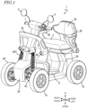
- FIG. 1 is a perspective view showing a vehicle 1 according to the embodiment.
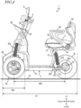
- FIG. 2 is a left side view showing the vehicle 1.
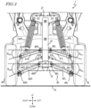
- FIG. 3 is a front view showing the vehicle 1.
- the vehicle 1 is, for example, a handle-type electric wheelchair, but the present invention is not limited thereto. An example in which the vehicle 1 is a handle-type electric wheelchair will be described below.
- the vehicle 1 includes a vehicle body frame 2 ( FIG. 2 ).
- the vehicle body frame 2 includes an under frame 2u, a rear frame 2r, a seat frame 2s and a front frame 2f ( FIG. 3 ).
- the under frame 2u extends in the front-rear direction of the vehicle 1.
- the rear frame 2r extends upward from a rear portion of the under frame 2u, and the seat frame 2s extends rearward from an upper portion of the rear frame 2r.
- the front frame 2f extends upward from a front portion of the under frame 2u.
- a head tube 22 ( FIG. 2 ) is provided on an upper portion of the front frame 2f ( FIG. 3 ).
- the head tube 22 rotatably supports a steering column 26 passing through the inside thereof.
- a handle 6 that is steered by the passenger is provided on an upper end portion of the steering column 26.
- An accelerator operator 7 ( FIG. 1 ) and a pair of, left and right, rearview mirrors 9 are provided on the handle 6.
- a body cover 28 is provided so as to cover a part of the vehicle body frame 2.
- a front guard 29 is provided on the body cover 28. With the front guard 29 arranged forward of the passenger, it is possible to provide the passenger with a sense of security when driving.
- the front suspension 40 includes an upper arm 41L, a lower arm 42L and a shock absorber 45L.
- One end of the upper arm 41L is rotatably supported by the front frame 2f via a pivot 46L.
- the other end of the upper arm 41L rotatably supports a knuckle arm 44L via a pivot 47L.
- One end of the lower arm 42L is rotatably supported by the front frame 2f via a pivot 48L.
- the other end of the lower arm 42L rotatably supports the knuckle arm 44L via a pivot 49L.
- the knuckle arm 44L rotatably supports the front wheel 4L.
- the front suspension 40 includes an upper arm 41R, a lower arm 42R and a shock absorber 45R.
- One end of the upper arm 41R is rotatably supported by the front frame 2f via a pivot 46R.
- the other end of the upper arm 41R rotatably supports a knuckle arm 44R via a pivot 47R.
- One end of the lower arm 42R is rotatably supported by the front frame 2f via a pivot 48R.
- the other end of the lower arm 42R rotatably supports the knuckle arm 44R via a pivot 49R.
- the knuckle arm 44R rotatably supports the front wheel 4R.
- the front suspension 40 rotatably supports the front wheels 4L and 4R via the knuckle arms 44L and 44R.
- the front wheels 4L and 4R are steered wheels.
- the front suspension 40 may be referred to as a double wishbone-type suspension.
- the arm shape of the double wishbone-type suspension is not limited to the A-letter shape (V-letter shape).
- double wishbone-type is a generic term for a suspension system in which the wheels are supported by a pair of, upper and lower, arms.
- the front frame 2F is provided with a suspension tower 27.
- the upper portions of the shock absorbers 45L and 45R are rotatably supported by the suspension tower 27.
- the lower portion of the shock absorber 45L rotatably supports the upper arm 41L.
- the lower portion of the shock absorber 45R rotatably supports the upper arm 41R.
- the front frame 2f extends in the up-down direction at a position in the vicinity of the center in the vehicle width direction.
- the frame portion to which the suspension is attached is required to have high strength because the impact received by the suspension from the road surface is transmitted thereto.
- the suspension tower 27 is provided in the vicinity of the left and right end portions of the vehicle body, high strength needs to be ensured in the frame portion extending in the left-right direction from the central portion in the vehicle width direction, thereby resulting in a large vehicle body weight.
- shock absorbers 45L and 45R are attached to the upper arms 41L and 41R.
- FIG. 4A and FIG. 4B are plan views showing an overview of the steering mechanism of the vehicle 1.
- a pitman arm 49 is attached to the lower end portion of the steering column 26.
- One end of a tie rod 43L and one end of a tie rod 43R are each rotatably connected to pitman arm 49.
- the other end of the tie rod 43L is rotatably connected to the knuckle arm 44L.
- the other end of the tie rod 43R is rotatably connected to the knuckle arm 44R.
- FIG. 4A shows the steering mechanism when traveling straight.
- the passenger turns the handle 6 ( FIG. 1 ).
- the steering force generated by the passenger turning the handle 6 is transmitted to the pitman arm 49 via the steering column 26.
- the pitman arm 49 rotates around the steering column 26 and the steering force is transmitted to the front wheels 4L and 4R via the tie rods 43L and 43R and the knuckle arms 44L and 44R.
- the transmitted steering force changes the steering angle of the front wheels 4L and 4R, allowing the vehicle 1 to travel while turning left or right.
- a seat 3, on which the passenger is seated, is provided on the seat frame 2s.
- the seat 3 includes a seat base 31 provided on the seat frame 2s and a cushion 32 provided on the seat base 31.
- the seat base 31 is also called a plate member or a bottom plate.
- the seat base 31 forms the bottom portion of the seat 3 and serves to ensure the strength of the seat 3 as a whole. Therefore, the sheet base 31 is formed from a relatively rigid material.
- the material of the sheet base 31 can be, for example, but not limited to, a metal material or a synthetic resin material such as polypropylene.
- the cushion 32 is overlaid on the surface of the seat base 31.
- the cushion 32 can be formed from a material that retains appropriate elasticity over time to maintain good ride comfort.
- polyurethane foam urethane foam
- urethane foam can be used as the material for the cushion 32.
- armrests 38 are provided on which the passenger places the arms.
- the armrests 38 also serve as side guards.
- a backrest 39 is provided at the rear portion of the seat 3, on which the passenger leans.
- the under frame 2u is provided with a footboard 8 ( FIG. 1 ) on which the passenger places the feet.
- the footboard 8 has a non-slip finish.
- the upper surface of the footboard 8 has a generally flat shape so that the passenger can easily get in and out of the vehicle.
- FIG. 2 An independent rear suspension 50 ( FIG. 2 ) is provided at the rear portion of the under frame 2u.
- FIG. 5 is a front view showing the rear suspension 50.
- the rear suspension 50 may be referred to as a trailing arm suspension.
- the rear suspension 50 includes rear arms 51L and 51R and shock absorbers 55L and 55R.
- the rear arms 51L and 51R are swing arms.
- the front portion of the rear arm 51L is rotatably supported on the left rear portion of the under frame 2u via a pivot 56L.
- the front portion of the rear arm 51R is rotatably supported on the right rear portion of the under frame 2u via a pivot 56R.
- the upper portion of the shock absorber 55L and the upper portion of the shock absorber 55R are each rotatably supported by the rear frame 2r ( FIG. 2 ).
- the lower portion of the shock absorber 55L rotatably supports the rear arm 51L.
- the lower portion of the shock absorber 55R rotatably supports the rear arm 51R.
- An electric motor 60L is provided at the rear portion of the rear arm 51L.
- the electric motor 60L is an in-wheel motor, and the rear wheel 5L is provided on the electric motor 60L.
- the rear suspension 50 rotatably supports the rear wheel 5L via the electric motor 60L.
- the electric motor 60R is provided at the rear portion of the rear arm 51R.
- the electric motor 60R is an in-wheel motor, and the rear wheel 5R is provided on the electric motor 60R.
- the rear suspension 50 rotatably supports the rear wheel 5R via the electric motor 60R.
- the rear wheels 5L and 5R are drive wheels.
- the vehicle 1 of the present embodiment employs large-sized wheels 4L, 4R, 5L and 5R.
- the outer diameters of the front wheels and the rear wheels are, for example, but not limited to, 14 inches or more.
- two electric motors 60L and 60R are used to drive the rear wheels 5L and 5R independently of each other.
- By controlling the rotation of the left wheels and that of the right wheels independently it is possible to enhance the stability of the behavior of the vehicle 1 when turning.
- vehicles that have differential gears when one drive wheel idles, it is difficult for the driving force to be transmitted to the other drive wheel.
- the present embodiment even if one of the rear wheels 5L and 5R idles, the other can provide grip so as to continue driving stably.
- the electric motors driving the rear wheels 5L and 5R are not limited to in-wheel motors.
- a single electric motor may transmit driving power to the rear wheels 5L and 5R.
- the vehicle 1 may be four-wheel drive.
- in-wheel motors are also provided for each of the front wheels 4L and 4R.
- the driving force may be transmitted from one electric motor to the front wheels 4L and 4R.
- the driving force may be transmitted from one electric motor to each of the front wheels 4L and 4R and the rear wheels 5L and 5R.
- the vehicle 1 of the present embodiment includes the independent front suspension 40 and the independent rear suspension 50.
- Two electric motors 60L and 60R are used to drive the rear wheels 5L and 5R independently of each other.
- rear suspension 50 is not limited to an independent suspension, but may be an axle suspension.
- the present embodiment employs in-wheel motors as the electric motor. This eliminates the need to ensure space for arranging the electric motor and the power transmission mechanism in the body part of the vehicle, thereby saving space. Since a drive shaft extending in the left-right direction of the vehicle 1 is not required, the rear suspension 50 is not restricted by the drive shaft. In the rear suspension 50, the rear arms 51L and 51R extend in the front-rear direction and the pivots 56L and 56R are located forward relative to a rotation shaft 57 of the rear wheel 5L and 5R. With such a configuration, it is possible to increase the wheel stroke of the rear suspension 50.
- the wheel stroke of the rear suspension 50 is, for example, but not limited to, 60 mm or more. As the wheel stroke is as large as 60 mm or more, it is possible to improve the driving performance on unpaved roads and bumps.
- the upper limit of the wheel stroke of the rear suspension 50 may vary depending on the size of the vehicle 1, and is for example, but not limited to, 150 mm.
- the vehicle 1 may include a drive shaft.
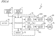
- FIG. 6 is a block diagram showing the electrical configuration of the vehicle 1.
- the vehicle 1 includes a control device 70.
- the control device 70 controls the operation of the vehicle 1.
- the control device 70 is, for example, a Motor Control Unit (MCU).
- MCU Motor Control Unit
- the control device 70 includes a semiconductor integrated circuit, such as a microcontroller, a signal processor, etc., capable of performing digital signal processing.
- the control device 70 includes a processor 71, a memory 72 and drive circuits 73L and 73R.
- the processor 71 controls the operation of the electric motors 60L and 60R and the operation of the various parts of the vehicle 1.
- the memory 72 stores a computer program that defines procedures for controlling the operation of the electric motors 60L and 60R and the various parts of the vehicle 1.
- the processor 71 reads the computer program from the memory 72 and performs various controls.
- the control device 70 is supplied with electric power from the battery 10.
- the control device 70 and the battery 10 can be installed at any position of the vehicle 1, for example, but not limited to, downward of the seat 3.
- the battery 10 can be provided so as to be removable from the vehicle 1.
- the battery 10 may be attached/removed to/from the rear of the seat 3. By arranging the battery 10 at an end portion of the vehicle around the seat 3, the passenger can easily attach/remove the battery 10.
- the accelerator operator 7 outputs to the processor 71 a signal in accordance with the amount by which the accelerator is operated by the passenger.
- the steering angle sensor 75 is provided on the head tube 22 or the steering column 26, for example, and outputs a signal to the processor 71 in accordance with the angle of rotation of the steering column 26.
- the electric motor 60L is provided with a rotation sensor 61L.
- the rotation sensor 61L detects the rotation angle of the electric motor 60L and outputs a signal in accordance with the rotation angle to the processor 71 and the drive circuit 73L.
- the processor 71 and the drive circuit 73L calculate the rotation speed of the electric motor 60L from the output signal of the rotation sensor 61L.
- the electric motor 60R is provided with a rotation sensor 61R.
- the rotation sensor 61R detects the rotation angle of the electric motor 60R and outputs a signal in accordance with the rotation angle to the processor 71 and the drive circuit 73R.
- the processor 71 and the drive circuit 73R calculate the rotation speed of the electric motor 60R from the output signal of the rotation sensor 61R.
- the sizes of the rear wheels 5L and 5R are stored in the memory 72 in advance, and the driving speed of the vehicle 1 can be calculated from the rotation speed of the electric motors 60L and 60R.
- the processor 71 calculates, and transmits to the drive circuits 73L and 73R, a command value for generating an appropriate driving force from the output signal of the accelerator operator 7, the output signal of the steering angle sensor 75, the traveling speed of the vehicle, and information stored in the memory 72, etc.
- the processor 71 can send different command values to the drive circuits 73L and 73R depending on the driving condition of the vehicle.
- the drive circuits 73L and 73R are, for example, inverters.
- the drive circuit 73L supplies a drive current in accordance with the command value from the processor 71 to the electric motor 60L.
- the drive circuit 73R supplies the drive current in accordance with the command value from the processor 71 to the electric motor 60L.
- the electric motors 60L and 60R to which the drive current is supplied rotate, thereby causing the rear wheels 5L and 5R to rotate. If the electric motors 60L and 60R include decelerators, the rotation is transmitted to the rear wheels 5L and 5R via those decelerators.
- the vehicle 1 of the present embodiment includes wheels 4L, 4R, 5L and 5R with a larger outer diameter.
- the overall length (length in the front-rear direction) of the vehicle 1 may be limited.
- the Japanese Industrial Standards "JIS T 9208:2016" for handle-type electric wheelchairs limits the overall length of the vehicle to 1200 mm or less.
- the wheelbase will be shorter if the outer diameter of the wheels is increased.
- the outer diameters Dw of the wheels 4L, 4R, 5L and 5R of the present embodiment are relatively large, for example, more than 0.26 times the overall length Lo of the vehicle 1.
- the outer diameter Dw of the wheels is relatively large, for example, more than 0.43 times the wheelbase WB of the vehicle 1.
- the upper limit of the outer diameter Dw of the wheel is, for example, but not limited to, 0.4 times the overall length Lo of the vehicle 1.
- the wheel outer diameter Dw is, for example, but not limited to, at most 0.67 times the wheelbase WB.
- the front suspension 40 of the present embodiment with which it is possible to increase the steering angle and the wheel stroke will now be described in detail.
- FIG. 3 shows the vehicle 1 in a predetermined state, stationary on a level road surface 15 with a weight having a mass of 75 kg on the seat 3 ( FIG. 1 ).
- the weight is one of the weights specified in the Japanese Industrial Standards "JIS T 9208:2016” for handle-type electric wheelchairs. With such a weight on the seat 3, it is possible to simulate the state where a human rides in the vehicle 1.
- the upper arm 41L and the lower arm 42L of the front suspension 40 are inclined so that the height gradually decreases from the central portion in the vehicle width direction (the left-right direction) to the left. That is, the upper arm 41L and the lower arm 42L have anhedral angles ⁇ 41L and ⁇ 42L .
- the anhedral angle is the angle between the vehicle width direction and the longitudinal direction of the arm as the front suspension 40 is viewed from front. When the vehicle 1 is stationary on the level road surface 15, the vehicle width direction can be parallel to the horizontal direction.
- the longitudinal direction of the arm is, for example, the direction extending from the center of the pivot on the front frame 2f side toward the center of the pivot on the knuckle arm side.
- the anhedral angle may be referred to as a negative dihedral angle.
- the upper arm 41R and the lower arm 42R of the front suspension 40 are inclined so that the height gradually decreases from the central portion in the vehicle width direction toward the right side. That is, the upper arm 41R and the lower arm 42R have anhedral angles ⁇ 41R and ⁇ 42R .
- the anhedral angles ⁇ 41L and ⁇ 41R of the upper arms 41L and 41R are 15 degrees or more, for example.
- the anhedral angles ⁇ 42L and ⁇ 42R of the lower arms 42L and 42R are 20 degrees or more, for example. With the large anhedral angles of the arms, it is possible to increase the roll rigidity of the vehicle 1.
- the upper limit of the anhedral angles ⁇ 41L and ⁇ 41R of the upper arms 41L and 41R is, for example, but not limited to, 20 degrees.
- the upper limit of the anhedral angle ⁇ 42L and ⁇ 42R of the lower arms 42L and 42R is, for example, but not limited to, 25 degrees.
- each arm of the front suspension 40 has an anhedral angle even when the above-mentioned weight is absent on the seat 3 (corresponding to a state where no passenger is on board).
- the anhedral angle ⁇ 42L of the lower arm 42L is greater than the anhedral angle ⁇ 41L of the upper arm 41L.
- the difference between the anhedral angle ⁇ 42L of the lower arm 42L and the anhedral angle ⁇ 41L of the upper arm 41L is, for example, 5 degrees or more.
- the anhedral angle ⁇ 42R of the lower arm 42R is greater than the anhedral angle ⁇ 41R of the upper arm 41R.
- the difference between the anhedral angle ⁇ 42R of the lower arm 42R and the anhedral angle ⁇ 41R of the upper arm 41R is, for example, 5 degrees or more.
- the upper limit of the difference between the anhedral angle of the lower arm and the anhedral angle of the upper arm is, for example, but not limited to, 9 degrees.
- the upper limit of the anhedral angle difference may be 8 degrees.
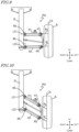
- FIG. 7 and FIG. 8 are front views showing the front suspension 40.
- the features of the upper arm 41L, the lower arm 42L, the knuckle arm 44L and the front wheel 4L will now be described primarily, but the features of the upper arm 41R, the lower arm 42R, the knuckle arm 44R and the front wheel 4R are the same. Since the steered wheels in the present embodiment are the front wheels, the front wheels may be referred to as the steered wheels.
- FIG. 7 shows the front suspension 40 when the steered wheel 4L moves in the upward direction, i.e., when the front suspension 40 is retracted.
- FIG. 8 shows the front suspension 40 when the steered wheel 4L moves in the downward direction, i.e., when the front suspension 40 is extended.
- the present inventors have found that by making the anhedral angle ⁇ 42L of the lower arm 42L ( FIG. 3 ) larger than the anhedral angle ⁇ 41L of the upper arm 41L, it is possible to increase the amount of change in the camber angle ⁇ c of the steered wheel 4L when the front suspension 40 strokes.
- the amount of change in the camber angle ⁇ c with respect to the wheel stroke can be set to 5 degrees or more.
- the amount of change in the angle between the longitudinal direction of the arm and the tire center line means that there is little change in the positional relationship between the arm and the steered wheel.
- FIG. 9 and FIG. 10 are front views showing, as a comparative example, a front suspension 40a where the anhedral angle ⁇ 42L of the lower arm 42L ( FIG. 3 ) and the anhedral angle ⁇ 41L of the upper arm 41L are equal to each other.
- the longitudinal direction LD1 of the upper arm 41L is parallel to the longitudinal direction LD2 of the lower arm 42L.
- FIG. 9 shows the front suspension 40a when the steered wheel 4L moves in the upward direction.
- FIG. 10 shows the front suspension 40a when the steered wheel 4L moves in the downward direction.
- the camber angle does not substantially change. Therefore, the amount of change in the angle ⁇ u between the longitudinal direction LD1 of the upper arm 41L and the tire center line CtL when moving in a stroke is large. Similarly, the amount of change in the angle ⁇ l between the longitudinal direction LD2 of the lower arm 42L and the tire center line CtL when moving in a stroke is large.
- the amount of change in the angle between the longitudinal direction of the arm and the tire center line being large means that the change in the positional relationship between the arm and the steered wheel is large. As the positional relationship between the arm and the steered wheel changes significantly, it is difficult to ensure clearance.
- the change in the positional relationship between the arm and the steered wheel is small.
- the camber angle ⁇ c of the steered wheel 4L when the front suspension 40 makes a bound stroke, can be a negative camber.
- the camber angle ⁇ c of the steered wheel 4L can be a positive camber.
- the upper limit of the amount of change in the camber angle ⁇ c with respect to wheel stroke is, for example, but not limited to, 10 degrees.
- FIG. 11 is a front view showing the front suspension 40 of the present embodiment.
- FIG. 11 shows the front suspension 40 in the bound stroke state is indicated by a solid line, and the front suspension 40 in the rebound stroke state is indicated by a dotted line.
- the swing angle ⁇ s1 of the upper arm 41L and the swing angle ⁇ s2 of the lower arm 42L are each 30 degrees or more, for example. With the large swing angle of 30 degrees or more, it is possible to improve the driving performance on unpaved roads and bumps.
- the wheel stroke WS is, for example, 60 mm or more. With the large wheel stroke WS of 60 mm or more, it is possible to improve the driving performance on unpaved roads and bumps.
- the wheel stroke WS is 0.5 times or more of the length D 41 ( FIG. 7 ) in the longitudinal direction of the upper arm 41L and 0.5 times or more of the length D 42 in the longitudinal direction of the lower arm 42L.
- the length in the longitudinal direction of the arm is, for example, the length between the center of the pivot on the front frame 2F side and the center of the pivot on the knuckle arm side.
- the upper limit of the swing angles ⁇ s1 and ⁇ s2 is, for example, but not limited to, 60 degrees.
- the upper limit of the wheel stroke WS is, for example, but not limited to, 150 mm.
- the wheel stroke WS is, for example, but not limited to, at maximum 0.80 times the length in the longitudinal direction of the arm.
- FIG. 12 are views showing the steering angle of the steered wheels 4L and 4R.
- the reference signs CtL and CtR in FIG. 12 represent the tire center lines of the steered wheels 4L and 4R.
- FIG. 12 shows the steering angle when the vehicle 1 is turning right.
- it is possible to increase the clearance between the front suspension 40 and the steered wheel 4L it is possible to increase the steering angle of the steered wheels 4L and 4R.
- the steered wheel 4R is the inner wheel and the steered wheel 4L is the outer wheel.
- the maximum value of the steering angle of the inner wheel is, for example, 50 degrees or more
- the maximum value of the steering angle of the outer wheel is, for example, 35 degrees or more.
- the steering angle of the inner wheel is larger than the steering angle of the outer wheel.
- Such a relationship in the steering angle between the inner wheel and the outer wheel can be achieved, for example, by employing Ackermann-type steering. It may also be realized, for example, by a steering system in which the steering angle of the inner wheel and the steering angle of the outer wheel are controlled independently of each other.
- the maximum value of the steering angle of the inner wheel is, for example, but not limited to, 80 degrees or less.
- the maximum value of the steering angle of the outer wheel is, for example, but not limited to, 80 degrees or less.
- the minimum turning radius of the vehicle 1 can be as small as 2.5 times or less of the tread width TW of the steered wheels 4L and 4R.
- the minimum turning radius of the vehicle 1 is, for example, 1400 mm or less. As the minimum turning radius of the vehicle 1 is small, it is possible to turn in a small radius.
- vehicle 1 is a four-wheeled handle-type electric wheelchair in the description of the embodiment above, the vehicle 1 is not limited thereto.
- vehicle 1 may be a joystick-type electric wheelchair.
- vehicle 1 is not limited to a wheelchair, but may be another vehicle.
- the number of wheels of the vehicle 1 is not limited to four wheels.
- the number of wheels may be three or more.
- the drive source for driving the wheels is not limited to an electric motor, but may be an internal combustion engine.
- the driving force may be transmitted from one drive source to multiple wheels.
- the vehicle 1 includes: at least three wheels including a steered wheel 4L, 4R; at least one drive source 60L, 60R that drives at least two of the wheels; and a front suspension 40 having an upper arm 41L, 41R and a lower arm 42L, 42R supporting the steered wheel 4L, 4R, wherein: in a state where the vehicle 1 is stationary on a level road surface 15, an anhedral angle of the lower arm 42L, 42R is larger than an anhedral angle of the upper arm 41L, 41R; and a difference between the anhedral angle of the lower arm 42L, 42R and the anhedral angle of the upper arm 41L, 41R is 5 degrees or more.
- anhedral angle of the lower arm 42L, 42R is larger than the anhedral angle of the upper arm 41L, 41R, with the anhedral angle difference being 5 degrees or more, it is possible to reduce the amount of change in the angle between the longitudinal direction of each of the upper arm 41L, 41R and the lower arm 42L, 42R and the tire center line when the front suspension 40 moves in a stroke.
- This increases the clearance between the front suspension 40 and the steered wheel 4L, 4R, and it is possible to both increase the wheel stroke WS and increase the steering angle of the steered wheel 4L, 4R.
- the difference between the anhedral angle of the lower arm 42L, 42R and the anhedral angle of the upper arm 41L, 41R may be 5 degrees or more and 9 degrees or less.
- the amount of change in a camber angle of the steered wheel 4L, 4R relative to the wheel stroke WS of the front suspension 40 may be 5 degrees or more.
- the amount of change in the camber angle of the steered wheel 4L, 4R relative to the wheel stroke WS of the front suspension 40 may be 5 degrees or more and 10 degrees or less.
- the camber angle of the steered wheel 4L, 4R when the front suspension 40 moves in a bound stroke, the camber angle of the steered wheel 4L, 4R may be a negative camber; and when the front suspension 40 moves in a rebound stroke, the camber angle of the steered wheel 4L, 4R may be a positive camber.
- the anhedral angle of the upper arm 41L, 41R may be 15 degrees or more, and the anhedral angle of the lower arm 42L, 42R may be 20 degrees or more.
- anhedral angle of the upper arm 41L, 41R and the anhedral angle of the lower arm 42L, 42R are as large as 15 degrees or more and 20 degrees or more, respectively, it is possible to increase the roll rigidity.
- the anhedral angle of the upper arm 41L, 41R may be 15 degrees or more and 20 degrees or less, and the anhedral angle of the lower arm 42L, 42R may be 20 degrees or more and 25 degrees or less.
- a swing angle of each of the upper arm 41L, 41R and the lower arm 42L, 42R may be 30 degrees or more.
- swing angle of the upper arm 41L, 41R and the swing angle of the lower arm 42L, 42R are as large as 30 degrees or more, it is possible to improve the driving performance on unpaved roads and bumps.
- the swing angle of each of the upper arm 41L, 41R and the lower arm 42L, 42R may be 30 degrees or more and 60 degrees or less.
- the wheel stroke WS of the front suspension 40 may be 60 mm or more.
- the wheel stroke WS is as large as 60 mm or more, it is possible to improve the driving performance on unpaved roads and bumps.
- the wheel stroke WS of the front suspension 40 may be 60 mm or more and 150 mm or less.
- the wheel stroke WS of the front suspension 40 may be 0.5 times or more of the length in the longitudinal direction of each of the upper arm 41L, 41R and the lower arm 42L, 42R.
- the wheel stroke WS is as large as 0.5 times or more of the length in the longitudinal direction of each of the upper arm 41L, 41R and the lower arm 42L, 42R, it is possible to improve the driving performance on unpaved roads and bumps.
- the wheel stroke WS of the front suspension 40 may be 0.5 times or more and 0.80 times or less of the length in the longitudinal direction of each of the upper arm 41L, 41R and the lower arm 42L, 42R.
- the steered wheel 4L, 4R may include an inner wheel and an outer wheel; a maximum value of a steering angle of the inner wheel may be 50 degrees or more; and a maximum value of a steering angle of the outer wheel may be 35 degrees or more.
- the maximum value of the steering angle of the inner wheel may be 50 degrees or more and 80 degrees or less; and the maximum value of the steering angle of the outer wheel may be 35 degrees or more and 80 degrees or less.
- the minimum turning radius of the vehicle 1 may be 2.5 times or less of the tread width of the steered wheels 4L, 4R.
- the minimum turning radius of the vehicle 1 may be 1400 mm or less.
- an outer diameter Dw of the steered wheel 4L, 4R may be 0.26 times or more of an overall length Lo of the vehicle 1.
- the outer diameter Dw of the steered wheel 4L, 4R is as large as 0.26 times or more of the overall length Lo of the vehicle 1, it is possible to improve the driving performance on unpaved roads and bumps and to improve the ride comfort.
- the outer diameter Dw of the steered wheel 4L, 4R may be 0.26 times or more and 0.4 times or less of the overall length Lo of the vehicle 1.
- the outer diameter Dw of the steered wheel 4L, 4R is large relative to the overall length Lo of the vehicle 1, it is possible to improve the driving performance on unpaved roads and bumps and to improve the ride comfort.
- the outer diameter Dw of the steered wheel 4L, 4R may be 0.43 times or more of a wheelbase of the vehicle 1.
- the outer diameter Dw of the steered wheel 4L, 4R is as large as 0.43 times or more of the wheelbase of the vehicle 1, it is possible to improve the driving performance on unpaved roads and bumps and to improve the ride comfort.
- the outer diameter Dw of the steered wheel 4L, 4R may be 0.43 times or more and 0.67 times or less of a wheelbase of the vehicle 1.
- the outer diameter Dw of the steered wheel 4L, 4R is large relative to the wheelbase of the vehicle 1, it is possible to improve the driving performance on unpaved roads and bumps and to improve the ride comfort.
- the vehicle 1 may be a handle-type electric wheelchair, and may further include a handle 6 that is steered by a passenger, and a seat 3 on which the passenger is seated.
- the present invention is particularly useful in the field of vehicles.
Landscapes
- Engineering & Computer Science (AREA)
- Mechanical Engineering (AREA)
- Health & Medical Sciences (AREA)
- Life Sciences & Earth Sciences (AREA)
- Animal Behavior & Ethology (AREA)
- General Health & Medical Sciences (AREA)
- Public Health (AREA)
- Veterinary Medicine (AREA)
- Vehicle Body Suspensions (AREA)
- Automatic Cycles, And Cycles In General (AREA)
- Axle Suspensions And Sidecars For Cycles (AREA)
Abstract
Description
- The present invention relates to a vehicle.
- A handle-type electric wheelchair has been known as one of the vehicles that run with a human on board (e.g., Patent Document No. 1). A handle-type electric wheelchair is sometimes referred to as an electric cart.
- Generally, handle-type electric wheelchairs are used for traveling on relatively flat paved roads. For example, the user can ride a handle-type electric wheelchair between home and a store to do shopping.
- Patent Document No. 1:
Japanese Laid-Open Patent Publication No. 2000-247155 - There is a need to further improve the driving performance of such vehicles.
- A vehicle according to an embodiment of the present invention is a vehicle including: at least three wheels including a steered wheel; at least one drive source that drives at least two of the wheels; and a suspension having an upper arm and a lower arm supporting the steered wheel, wherein: in a state where the vehicle is stationary on a level road surface, an anhedral angle of the lower arm is larger than an anhedral angle of the upper arm; and a difference between the anhedral angle of the lower arm and the anhedral angle of the upper arm is 5 degrees or more.
- As the anhedral angle of the lower arm is larger than the anhedral angle of the upper arm, with the anhedral angle difference being 5 degrees or more, it is possible to reduce the amount of change in the angle between the longitudinal direction of each of the upper arm and the lower arm and the tire center line when the suspension moves in a stroke. This increases the clearance between the suspension and the steered wheel, and it is possible to both increase the wheel stroke and increase the steering angle of the steered wheel.
- In one embodiment, the difference between the anhedral angle of the lower arm and the anhedral angle of the upper arm may be 5 degrees or more and 9 degrees or less.
- As the difference between the anhedral angle of the lower arm and the anhedral angle of the upper arm is large, it is possible to reduce the amount of change in the angle between the longitudinal direction of each of the upper arm and the lower arm and the tire center line when the suspension moves in a stroke.
- In one embodiment, the amount of change in a camber angle of the steered wheel relative to the wheel stroke of the suspension may be 5 degrees or more.
- As the camber angle of the steered wheel significantly changes in response to the stroke of the suspension, it is possible to reduce the amount of change in the angle between the longitudinal direction of each of the upper arm and the lower arm and the tire center line.
- In one embodiment, the amount of change in the camber angle of the steered wheel relative to the wheel stroke of the suspension may be 5 degrees or more and 10 degrees or less.
- As the camber angle of the steered wheel significantly changes in response to the stroke of the suspension, it is possible to reduce the amount of change in the angle between the longitudinal direction of each of the upper arm and the lower arm and the tire center line.
- In one embodiment, when the suspension moves in a bound stroke, the camber angle of the steered wheel may be a negative camber; and when the suspension moves in a rebound stroke, the camber angle of the steered wheel may be a positive camber.
- As the camber angle changes between a negative camber and a positive camber in response to the stroke of the suspension, it is possible to reduce the amount of change in the angle between the longitudinal direction of each of the upper arm and the lower arm and the tire center line.
- In one embodiment, in a state where the vehicle is stationary on the level road surface, the anhedral angle of the upper arm may be 15 degrees or more, and the anhedral angle of the lower arm may be 20 degrees or more.
- As the anhedral angle of the upper arm and the anhedral angle of the lower arm are as large as 15 degrees or more and 20 degrees or more, respectively, it is possible to increase the roll rigidity.
- In one embodiment, in a state where the vehicle is stationary on the level road surface, the anhedral angle of the upper arm may be 15 degrees or more and 20 degrees or less, and the anhedral angle of the lower arm may be 20 degrees or more and 25 degrees or less.
- As the anhedral angle of the upper arm and the anhedral angle of the lower arm are large, it is possible to increase the roll rigidity.
- In one embodiment, a swing angle of each of the upper arm and the lower arm may be 30 degrees or more.
- As the swing angle of the upper arm and the swing angle of the lower arm are as large as 30 degrees or more, it is possible to improve the driving performance on unpaved roads and bumps.
- In one embodiment, the swing angle of each of the upper arm and the lower arm may be 30 degrees or more and 60 degrees or less.
- As the swing angle of the upper arm and the swing angle of the lower arm are large, it is possible to improve the driving performance on unpaved roads and bumps.
- In one embodiment, the wheel stroke of the suspension may be 60 mm or more.
- As the wheel stroke is as large as 60 mm or more, it is possible to improve the driving performance on unpaved roads and bumps.
- In one embodiment, the wheel stroke of the suspension may be 60 mm or more and 150 mm or less.
- As the wheel stroke is large, it is possible to improve the driving performance on unpaved roads and bumps.
- In one embodiment, the wheel stroke of the suspension may be 0.5 times or more of the length in the longitudinal direction of each of the upper arm and the lower arm.
- As the wheel stroke is as large as 0.5 times or more of the length in the longitudinal direction of each of the upper arm and the lower arm, it is possible to improve the driving performance on unpaved roads and bumps.
- In one embodiment, the wheel stroke of the suspension may be 0.5 times or more and 0.80 times or less of the length in the longitudinal direction of each of the upper arm and the lower arm.
- As the wheel stroke is large, it is possible to improve the driving performance on unpaved roads and bumps.
- In one embodiment, the steered wheel may include an inner wheel and an outer wheel; a maximum value of a steering angle of the inner wheel may be 50 degrees or more; and a maximum value of a steering angle of the outer wheel may be 35 degrees or more.
- As the steering angle of the steered wheel is large, it is possible to reduce the minimum turning radius of the vehicle, and it is possible to turn in a small radius.
- In one embodiment, the maximum value of the steering angle of the inner wheel may be 50 degrees or more and 80 degrees or less, and the maximum value of the steering angle of the outer wheel may be 35 degrees or more and 80 degrees or less.
- As the steering angle of the steered wheel is large, it is possible to reduce the minimum turning radius of the vehicle, and it is possible to turn in a small radius.
- In one embodiment, the minimum turning radius of the vehicle may be 2.5 times or less of the tread width of the steered wheels.
- As the minimum turning radius for the tread width is small, it is possible to turn in a small radius.
- In one embodiment, the minimum turning radius of the vehicle may be 1400 mm or less.
- As the minimum turning radius of the vehicle is small, it is possible to turn in a small radius.
- In one embodiment, an outer diameter of the steered wheel may be 0.26 times or more of the overall length of the vehicle.
- As the outer diameter of the steered wheel is as large as 0.26 times or more of the overall length of the vehicle, it is possible to improve the driving performance on unpaved roads and bumps and to improve the ride comfort.
- In one embodiment, the outer diameter of the steered wheel may be 0.26 times or more and 0.4 times or less of the overall length of the vehicle.
- As the outer diameter of the steered wheel is large relative to the overall length of the vehicle, it is possible to improve the driving performance on unpaved roads and bumps and to improve the ride comfort.
- In one embodiment, the outer diameter of the steered wheel may be 0.43 times or more of a wheelbase of the vehicle.
- As the outer diameter of the steered wheel is as large as 0.43 times or more of the wheelbase of the vehicle, it is possible to improve the driving performance on unpaved roads and bumps and to improve the ride comfort.
- In one embodiment, the outer diameter of the steered wheel may be 0.43 times or more and 0.67 times or less of a wheelbase of the vehicle.
- As the outer diameter of the steered wheel is large relative to the wheelbase of the vehicle, it is possible to improve the driving performance on unpaved roads and bumps and to improve the ride comfort.
- In one embodiment, the vehicle may be a handle-type electric wheelchair, and may further include a handle that is steered by a passenger, and a seat on which the passenger is seated.
- It is possible to realize a handle-type electric wheelchair, wherein the wheel stroke is large and the steering angle of the steered wheel is large.
- As the anhedral angle of the lower arm is larger than the anhedral angle of the upper arm, with the anhedral angle difference being 5 degrees or more, it is possible to reduce the amount of change in the angle between the longitudinal direction of each of the upper arm and the lower arm and the tire center line when the suspension moves in a stroke. This increases the clearance between the suspension and the steered wheel, and it is possible to both increase the wheel stroke and increase the steering angle of the steered wheel.
-
-
FIG. 1 is a perspective view showing avehicle 1 according to the embodiment. -
FIG. 2 is a left side view showing thevehicle 1 according to the embodiment. -
FIG. 3 is a front view showing thevehicle 1 according to the embodiment. -
FIG. 4A is a plan view showing an overview of a steering mechanism included in thevehicle 1 according to the embodiment. -
FIG. 4B is a plan view showing an overview of the steering mechanism of thevehicle 1 according to the embodiment. -
FIG. 5 is a front view showing arear suspension 50 according to the embodiment. -
FIG. 6 is a block diagram showing the electrical configuration of thevehicle 1 according to the embodiment. -
FIG. 7 is a front view showing thefront suspension 40 according to the embodiment. -
FIG. 8 is a front view showing thefront suspension 40 according to the embodiment. -
FIG. 9 is a front view showing afront suspension 40a of a comparative example. -
FIG. 10 is a front view showing thefront suspension 40a according to the comparative example. -
FIG. 11 is a front view showing thefront suspension 40 according to the embodiment. -
FIG. 12 is a diagram showing the steering angles of steeredwheels - An embodiment of the present invention will now be described with reference to the drawings. Like elements are denoted by like reference signs, and will not be described redundantly. The terms front, rear, up, down, left and right, as used in the description below, refer to these directions as seen from a passenger seated in the seat of the vehicle. The left-right direction of the vehicle may be referred to as the vehicle width direction. Note that the following embodiment is illustrative, and the present invention is not limited to the following embodiment.
-
FIG. 1 is a perspective view showing avehicle 1 according to the embodiment.FIG. 2 is a left side view showing thevehicle 1.FIG. 3 is a front view showing thevehicle 1. In order to clearly illustrate the structure of thevehicle 1, a part of the body cover is omitted in the figures. Thevehicle 1 is, for example, a handle-type electric wheelchair, but the present invention is not limited thereto. An example in which thevehicle 1 is a handle-type electric wheelchair will be described below. - The
vehicle 1 includes a vehicle body frame 2 (FIG. 2 ). Thevehicle body frame 2 includes an underframe 2u, arear frame 2r, aseat frame 2s and afront frame 2f (FIG. 3 ). The underframe 2u extends in the front-rear direction of thevehicle 1. Therear frame 2r extends upward from a rear portion of theunder frame 2u, and theseat frame 2s extends rearward from an upper portion of therear frame 2r. Thefront frame 2f extends upward from a front portion of theunder frame 2u. - A head tube 22 (
FIG. 2 ) is provided on an upper portion of thefront frame 2f (FIG. 3 ). Thehead tube 22 rotatably supports asteering column 26 passing through the inside thereof. Ahandle 6 that is steered by the passenger is provided on an upper end portion of thesteering column 26. An accelerator operator 7 (FIG. 1 ) and a pair of, left and right, rearview mirrors 9 are provided on thehandle 6. - A
body cover 28 is provided so as to cover a part of thevehicle body frame 2. Afront guard 29 is provided on thebody cover 28. With thefront guard 29 arranged forward of the passenger, it is possible to provide the passenger with a sense of security when driving. - An
independent front suspension 40 is provided on thefront frame 2f (FIG. 3 ). Thefront suspension 40 includes anupper arm 41L, alower arm 42L and ashock absorber 45L. One end of theupper arm 41L is rotatably supported by thefront frame 2f via apivot 46L. The other end of theupper arm 41L rotatably supports aknuckle arm 44L via apivot 47L. One end of thelower arm 42L is rotatably supported by thefront frame 2f via apivot 48L. The other end of thelower arm 42L rotatably supports theknuckle arm 44L via apivot 49L. Theknuckle arm 44L rotatably supports thefront wheel 4L. - The
front suspension 40 includes anupper arm 41R, alower arm 42R and ashock absorber 45R. One end of theupper arm 41R is rotatably supported by thefront frame 2f via apivot 46R. The other end of theupper arm 41R rotatably supports aknuckle arm 44R via apivot 47R. One end of thelower arm 42R is rotatably supported by thefront frame 2f via apivot 48R. The other end of thelower arm 42R rotatably supports theknuckle arm 44R via apivot 49R. Theknuckle arm 44R rotatably supports thefront wheel 4R. Thefront suspension 40 rotatably supports thefront wheels knuckle arms front wheels - The
front suspension 40 may be referred to as a double wishbone-type suspension. In the present specification, the arm shape of the double wishbone-type suspension is not limited to the A-letter shape (V-letter shape). In the present specification, "double wishbone-type" is a generic term for a suspension system in which the wheels are supported by a pair of, upper and lower, arms. - The front frame 2F is provided with a
suspension tower 27. The upper portions of theshock absorbers suspension tower 27. The lower portion of theshock absorber 45L rotatably supports theupper arm 41L. The lower portion of theshock absorber 45R rotatably supports theupper arm 41R. - The
front frame 2f extends in the up-down direction at a position in the vicinity of the center in the vehicle width direction. The frame portion to which the suspension is attached is required to have high strength because the impact received by the suspension from the road surface is transmitted thereto. Where thesuspension tower 27 is provided in the vicinity of the left and right end portions of the vehicle body, high strength needs to be ensured in the frame portion extending in the left-right direction from the central portion in the vehicle width direction, thereby resulting in a large vehicle body weight. By providing thesuspension tower 27 on thefront frame 2f located in the vicinity of the center in the vehicle width direction, there is no longer a need for such a frame portion having high strength and extending in the left-right direction, thereby realizing a reduced vehicle body weight. - The
shock absorbers upper arms -
FIG. 4A and FIG. 4B are plan views showing an overview of the steering mechanism of thevehicle 1. Apitman arm 49 is attached to the lower end portion of thesteering column 26. One end of atie rod 43L and one end of atie rod 43R are each rotatably connected topitman arm 49. The other end of thetie rod 43L is rotatably connected to theknuckle arm 44L. The other end of thetie rod 43R is rotatably connected to theknuckle arm 44R. -
FIG. 4A shows the steering mechanism when traveling straight. When traveling through a curve, the passenger turns the handle 6 (FIG. 1 ). Referring toFIG. 4B , the steering force generated by the passenger turning thehandle 6 is transmitted to thepitman arm 49 via thesteering column 26. Thepitman arm 49 rotates around thesteering column 26 and the steering force is transmitted to thefront wheels tie rods knuckle arms front wheels vehicle 1 to travel while turning left or right. - Referring to
FIG. 1 andFIG. 2 , aseat 3, on which the passenger is seated, is provided on theseat frame 2s. Theseat 3 includes aseat base 31 provided on theseat frame 2s and acushion 32 provided on theseat base 31. - The
seat base 31 is also called a plate member or a bottom plate. Theseat base 31 forms the bottom portion of theseat 3 and serves to ensure the strength of theseat 3 as a whole. Therefore, thesheet base 31 is formed from a relatively rigid material. The material of thesheet base 31 can be, for example, but not limited to, a metal material or a synthetic resin material such as polypropylene. - The
cushion 32 is overlaid on the surface of theseat base 31. Thecushion 32 can be formed from a material that retains appropriate elasticity over time to maintain good ride comfort. For example, but not limited to, polyurethane foam (urethane foam) can be used as the material for thecushion 32. - On both sides of the
seat 3,armrests 38 are provided on which the passenger places the arms. Thearmrests 38 also serve as side guards. At the rear portion of theseat 3, abackrest 39 is provided on which the passenger leans. - The under
frame 2u is provided with a footboard 8 (FIG. 1 ) on which the passenger places the feet. Thefootboard 8 has a non-slip finish. The upper surface of thefootboard 8 has a generally flat shape so that the passenger can easily get in and out of the vehicle. - An independent rear suspension 50 (
FIG. 2 ) is provided at the rear portion of theunder frame 2u.FIG. 5 is a front view showing therear suspension 50. Therear suspension 50 may be referred to as a trailing arm suspension. - The
rear suspension 50 includesrear arms shock absorbers rear arms rear arm 51L is rotatably supported on the left rear portion of theunder frame 2u via apivot 56L. The front portion of therear arm 51R is rotatably supported on the right rear portion of theunder frame 2u via apivot 56R. - The upper portion of the
shock absorber 55L and the upper portion of theshock absorber 55R are each rotatably supported by therear frame 2r (FIG. 2 ). The lower portion of theshock absorber 55L rotatably supports therear arm 51L. The lower portion of theshock absorber 55R rotatably supports therear arm 51R. - An
electric motor 60L is provided at the rear portion of therear arm 51L. Theelectric motor 60L is an in-wheel motor, and therear wheel 5L is provided on theelectric motor 60L. Therear suspension 50 rotatably supports therear wheel 5L via theelectric motor 60L. Theelectric motor 60R is provided at the rear portion of therear arm 51R. Theelectric motor 60R is an in-wheel motor, and therear wheel 5R is provided on theelectric motor 60R. Therear suspension 50 rotatably supports therear wheel 5R via theelectric motor 60R. Therear wheels - The
vehicle 1 of the present embodiment employs large-sized wheels - In the present embodiment, two
electric motors rear wheels vehicle 1 when turning. With vehicles that have differential gears, when one drive wheel idles, it is difficult for the driving force to be transmitted to the other drive wheel. In the present embodiment, even if one of therear wheels - Note that the electric motors driving the
rear wheels rear wheels - Although a two-wheel drive configuration is illustrated here in which the
electric motors rear wheels vehicle 1 may be four-wheel drive. In that case, in-wheel motors are also provided for each of thefront wheels front wheels front wheels rear wheels - The
vehicle 1 of the present embodiment includes theindependent front suspension 40 and the independentrear suspension 50. Twoelectric motors rear wheels - Note that the
rear suspension 50 is not limited to an independent suspension, but may be an axle suspension. - The present embodiment employs in-wheel motors as the electric motor. This eliminates the need to ensure space for arranging the electric motor and the power transmission mechanism in the body part of the vehicle, thereby saving space. Since a drive shaft extending in the left-right direction of the
vehicle 1 is not required, therear suspension 50 is not restricted by the drive shaft. In therear suspension 50, therear arms pivots rotation shaft 57 of therear wheel rear suspension 50. - The wheel stroke of the
rear suspension 50 is, for example, but not limited to, 60 mm or more. As the wheel stroke is as large as 60 mm or more, it is possible to improve the driving performance on unpaved roads and bumps. The upper limit of the wheel stroke of therear suspension 50 may vary depending on the size of thevehicle 1, and is for example, but not limited to, 150 mm. - Since the drive shaft is not needed and the
rear arms 52L and 51R are not located near the central portion of the rear of the vehicle, it is possible to ensure space near the central portion of the rear of the vehicle. The space near the central portion of the rear of the vehicle makes it difficult for the main body portion of the vehicle to come into contact with the ground even when a large difference in position in the up-down direction occurs between the left and rightrear wheels rear suspension 50. Note that if the drive power is transmitted to therear wheels vehicle 1 may include a drive shaft. - Next, the control of the
electric motors FIG. 6 is a block diagram showing the electrical configuration of thevehicle 1. Thevehicle 1 includes acontrol device 70. Thecontrol device 70 controls the operation of thevehicle 1. Thecontrol device 70 is, for example, a Motor Control Unit (MCU). Typically, thecontrol device 70 includes a semiconductor integrated circuit, such as a microcontroller, a signal processor, etc., capable of performing digital signal processing. - The
control device 70 includes aprocessor 71, amemory 72 and drive circuits 73L and 73R. Theprocessor 71 controls the operation of theelectric motors vehicle 1. Thememory 72 stores a computer program that defines procedures for controlling the operation of theelectric motors vehicle 1. Theprocessor 71 reads the computer program from thememory 72 and performs various controls. Thecontrol device 70 is supplied with electric power from thebattery 10. Thecontrol device 70 and thebattery 10 can be installed at any position of thevehicle 1, for example, but not limited to, downward of theseat 3. Thebattery 10 can be provided so as to be removable from thevehicle 1. For example, thebattery 10 may be attached/removed to/from the rear of theseat 3. By arranging thebattery 10 at an end portion of the vehicle around theseat 3, the passenger can easily attach/remove thebattery 10. - The
accelerator operator 7 outputs to the processor 71 a signal in accordance with the amount by which the accelerator is operated by the passenger. Thesteering angle sensor 75 is provided on thehead tube 22 or thesteering column 26, for example, and outputs a signal to theprocessor 71 in accordance with the angle of rotation of thesteering column 26. - The
electric motor 60L is provided with arotation sensor 61L. Therotation sensor 61L detects the rotation angle of theelectric motor 60L and outputs a signal in accordance with the rotation angle to theprocessor 71 and the drive circuit 73L. Theprocessor 71 and the drive circuit 73L calculate the rotation speed of theelectric motor 60L from the output signal of therotation sensor 61L. - The
electric motor 60R is provided with arotation sensor 61R. Therotation sensor 61R detects the rotation angle of theelectric motor 60R and outputs a signal in accordance with the rotation angle to theprocessor 71 and the drive circuit 73R. Theprocessor 71 and the drive circuit 73R calculate the rotation speed of theelectric motor 60R from the output signal of therotation sensor 61R. The sizes of therear wheels memory 72 in advance, and the driving speed of thevehicle 1 can be calculated from the rotation speed of theelectric motors - The
processor 71 calculates, and transmits to the drive circuits 73L and 73R, a command value for generating an appropriate driving force from the output signal of theaccelerator operator 7, the output signal of thesteering angle sensor 75, the traveling speed of the vehicle, and information stored in thememory 72, etc. Theprocessor 71 can send different command values to the drive circuits 73L and 73R depending on the driving condition of the vehicle. - The drive circuits 73L and 73R are, for example, inverters. The drive circuit 73L supplies a drive current in accordance with the command value from the
processor 71 to theelectric motor 60L. The drive circuit 73R supplies the drive current in accordance with the command value from theprocessor 71 to theelectric motor 60L. Theelectric motors rear wheels electric motors rear wheels - As described above, the
vehicle 1 of the present embodiment includeswheels vehicle 1 may be limited. For example, the Japanese Industrial Standards "JIS T 9208:2016" for handle-type electric wheelchairs limits the overall length of the vehicle to 1200 mm or less. Thus, where the overall length of thevehicle 1 is limited, the wheelbase will be shorter if the outer diameter of the wheels is increased. - Referring to
FIG. 2 , the outer diameters Dw of thewheels vehicle 1. The outer diameter Dw of the wheels is relatively large, for example, more than 0.43 times the wheelbase WB of thevehicle 1. Thus, if the size of the wheel is relatively large, it is difficult to increase the steering angle of the wheel. The upper limit of the outer diameter Dw of the wheel is, for example, but not limited to, 0.4 times the overall length Lo of thevehicle 1. The wheel outer diameter Dw is, for example, but not limited to, at most 0.67 times the wheelbase WB. - When a wheel with a large outer diameter and width is used as a steered wheel, the suspension supporting the steered wheel and the steered wheel are more likely to interfere with each other, making it difficult to increase the steering angle of the steered wheel. However, vehicles such as handle-type electric wheelchairs are required to be able to turn in a small radius, and the steering angle of the steered wheels is required to be large. When wheels with a large outer diameter and width are used, it is easy for the wheels to interfere with the suspension when the wheels stroke in the up-down direction, thereby making it difficult to increase the wheel stroke.
- The
front suspension 40 of the present embodiment, with which it is possible to increase the steering angle and the wheel stroke will now be described in detail. - Referring to
FIG. 3 , the angles of theupper arms lower arms -
FIG. 3 shows thevehicle 1 in a predetermined state, stationary on alevel road surface 15 with a weight having a mass of 75 kg on the seat 3 (FIG. 1 ). The weight is one of the weights specified in the Japanese Industrial Standards "JIS T 9208:2016" for handle-type electric wheelchairs. With such a weight on theseat 3, it is possible to simulate the state where a human rides in thevehicle 1. - As shown in
FIG. 3 , theupper arm 41L and thelower arm 42L of thefront suspension 40 are inclined so that the height gradually decreases from the central portion in the vehicle width direction (the left-right direction) to the left. That is, theupper arm 41L and thelower arm 42L have anhedral angles θ41L and θ42L. The anhedral angle is the angle between the vehicle width direction and the longitudinal direction of the arm as thefront suspension 40 is viewed from front. When thevehicle 1 is stationary on thelevel road surface 15, the vehicle width direction can be parallel to the horizontal direction. The longitudinal direction of the arm is, for example, the direction extending from the center of the pivot on thefront frame 2f side toward the center of the pivot on the knuckle arm side. The anhedral angle may be referred to as a negative dihedral angle. - The
upper arm 41R and thelower arm 42R of thefront suspension 40 are inclined so that the height gradually decreases from the central portion in the vehicle width direction toward the right side. That is, theupper arm 41R and thelower arm 42R have anhedral angles θ41R and θ42R. - The anhedral angles θ41L and θ41R of the
upper arms lower arms vehicle 1. The upper limit of the anhedral angles θ41L and θ41R of theupper arms lower arms front suspension 40 has an anhedral angle even when the above-mentioned weight is absent on the seat 3 (corresponding to a state where no passenger is on board). - In the present embodiment, the anhedral angle θ42L of the
lower arm 42L is greater than the anhedral angle θ41L of theupper arm 41L. The difference between the anhedral angle θ42L of thelower arm 42L and the anhedral angle θ41L of theupper arm 41L is, for example, 5 degrees or more. The anhedral angle θ42R of thelower arm 42R is greater than the anhedral angle θ41R of theupper arm 41R. The difference between the anhedral angle θ42R of thelower arm 42R and the anhedral angle θ41R of theupper arm 41R is, for example, 5 degrees or more. By setting the difference between the anhedral angle of the lower arm and the anhedral angle of the upper arm to 5 degrees or more, it is possible to obtain a desired amount of change in the camber angle as will be described below. The upper limit of the difference between the anhedral angle of the lower arm and the anhedral angle of the upper arm is, for example, but not limited to, 9 degrees. For example, the upper limit of the anhedral angle difference may be 8 degrees. -
FIG. 7 and FIG. 8 are front views showing thefront suspension 40. The features of theupper arm 41L, thelower arm 42L, theknuckle arm 44L and thefront wheel 4L will now be described primarily, but the features of theupper arm 41R, thelower arm 42R, theknuckle arm 44R and thefront wheel 4R are the same. Since the steered wheels in the present embodiment are the front wheels, the front wheels may be referred to as the steered wheels. -
FIG. 7 shows thefront suspension 40 when the steeredwheel 4L moves in the upward direction, i.e., when thefront suspension 40 is retracted.FIG. 8 shows thefront suspension 40 when the steeredwheel 4L moves in the downward direction, i.e., when thefront suspension 40 is extended. - The present inventors have found that by making the anhedral angle θ42L of the
lower arm 42L (FIG. 3 ) larger than the anhedral angle θ41L of theupper arm 41L, it is possible to increase the amount of change in the camber angle θc of the steeredwheel 4L when thefront suspension 40 strokes. For example, the amount of change in the camber angle θc with respect to the wheel stroke can be set to 5 degrees or more. - As the camber angle θc changes significantly in response to the stroke of the
front suspension 40, it is possible to reduce the amount of change in the angle θu between the longitudinal direction LD1 of theupper arm 41L and the tire center line CtL when thefront suspension 40 strokes. It is possible to reduce the amount of change in the angle θl between the longitudinal direction LD2 of thelower arm 42L and the tire center line CtL when thefront suspension 40 strokes. - The amount of change in the angle between the longitudinal direction of the arm and the tire center line means that there is little change in the positional relationship between the arm and the steered wheel. Thus, it is possible to increase the clearance between the
front suspension 40 and the steeredwheel 4L. As the clearance is large, it is possible to increase the steering angle of the steeredwheel 4L and also to increase the wheel stroke. -
FIG. 9 and FIG. 10 are front views showing, as a comparative example, afront suspension 40a where the anhedral angle θ42L of thelower arm 42L (FIG. 3 ) and the anhedral angle θ41L of theupper arm 41L are equal to each other. In thefront suspension 40a, the longitudinal direction LD1 of theupper arm 41L is parallel to the longitudinal direction LD2 of thelower arm 42L.FIG. 9 shows thefront suspension 40a when the steeredwheel 4L moves in the upward direction.FIG. 10 shows thefront suspension 40a when the steeredwheel 4L moves in the downward direction. - When the
front suspension 40a moves in a stroke, the camber angle does not substantially change. Therefore, the amount of change in the angle θu between the longitudinal direction LD1 of theupper arm 41L and the tire center line CtL when moving in a stroke is large. Similarly, the amount of change in the angle θl between the longitudinal direction LD2 of thelower arm 42L and the tire center line CtL when moving in a stroke is large. - The amount of change in the angle between the longitudinal direction of the arm and the tire center line being large means that the change in the positional relationship between the arm and the steered wheel is large. As the positional relationship between the arm and the steered wheel changes significantly, it is difficult to ensure clearance.
- On the other hand, as described above, with the
front suspension 40 of the present embodiment, the change in the positional relationship between the arm and the steered wheel is small. Thus, it is possible to increase the clearance between thefront suspension 40 and the steeredwheel 4L, and it is possible to increase the steering angle of the steeredwheel 4L and to increase the wheel stroke. - In the present embodiment, when the
front suspension 40 makes a bound stroke, the camber angle θc of the steeredwheel 4L can be a negative camber. When thefront suspension 40 makes a rebound stroke, the camber angle θc of the steeredwheel 4L can be a positive camber. By varying the camber angle θc between the negative camber and the positive camber in response to the stroke of thefront suspension 40, it is possible to reduce the amount of change in the angle between the longitudinal direction of the arm and the tire center line. - Note that the upper limit of the amount of change in the camber angle θc with respect to wheel stroke is, for example, but not limited to, 10 degrees.
-
FIG. 11 is a front view showing thefront suspension 40 of the present embodiment.FIG. 11 shows thefront suspension 40 in the bound stroke state is indicated by a solid line, and thefront suspension 40 in the rebound stroke state is indicated by a dotted line. - In the present embodiment, since it is possible to increase the clearance between the
front suspension 40 and the steeredwheel 4L, it is possible to increase the arm swing angle and the wheel stroke. - The swing angle θs1 of the
upper arm 41L and the swing angle θs2 of thelower arm 42L are each 30 degrees or more, for example. With the large swing angle of 30 degrees or more, it is possible to improve the driving performance on unpaved roads and bumps. The wheel stroke WS is, for example, 60 mm or more. With the large wheel stroke WS of 60 mm or more, it is possible to improve the driving performance on unpaved roads and bumps. - The wheel stroke WS is 0.5 times or more of the length D41 (
FIG. 7 ) in the longitudinal direction of theupper arm 41L and 0.5 times or more of the length D42 in the longitudinal direction of thelower arm 42L. The length in the longitudinal direction of the arm is, for example, the length between the center of the pivot on the front frame 2F side and the center of the pivot on the knuckle arm side. As the wheel stroke WS is large relative to the length of the arm, it is possible to improve the driving performance on unpaved roads and bumps. - The upper limit of the swing angles θs1 and θs2 is, for example, but not limited to, 60 degrees. The upper limit of the wheel stroke WS is, for example, but not limited to, 150 mm. The wheel stroke WS is, for example, but not limited to, at maximum 0.80 times the length in the longitudinal direction of the arm.
- Next, the steering angle of the steered
wheels FIG. 12 are views showing the steering angle of the steeredwheels FIG. 12 represent the tire center lines of the steeredwheels FIG. 12 shows the steering angle when thevehicle 1 is turning right. In the present embodiment, since it is possible to increase the clearance between thefront suspension 40 and the steeredwheel 4L, it is possible to increase the steering angle of the steeredwheels - When the
vehicle 1 turns right, the steeredwheel 4R is the inner wheel and the steeredwheel 4L is the outer wheel. In the present embodiment, the maximum value of the steering angle of the inner wheel is, for example, 50 degrees or more, and the maximum value of the steering angle of the outer wheel is, for example, 35 degrees or more. - In this example, the steering angle of the inner wheel is larger than the steering angle of the outer wheel. Such a relationship in the steering angle between the inner wheel and the outer wheel can be achieved, for example, by employing Ackermann-type steering. It may also be realized, for example, by a steering system in which the steering angle of the inner wheel and the steering angle of the outer wheel are controlled independently of each other.
- As described above, with the steering angles of the steered
wheels vehicle 1, and it is possible to turn in a small radius. The maximum value of the steering angle of the inner wheel is, for example, but not limited to, 80 degrees or less. The maximum value of the steering angle of the outer wheel is, for example, but not limited to, 80 degrees or less. - As described above, in the present embodiment, it is possible to reduce the minimum turning radius of the
vehicle 1. For example, the minimum turning radius of thevehicle 1 can be as small as 2.5 times or less of the tread width TW of the steeredwheels vehicle 1 is, for example, 1400 mm or less. As the minimum turning radius of thevehicle 1 is small, it is possible to turn in a small radius. - While the
vehicle 1 is a four-wheeled handle-type electric wheelchair in the description of the embodiment above, thevehicle 1 is not limited thereto. Thevehicle 1 may be a joystick-type electric wheelchair. Thevehicle 1 is not limited to a wheelchair, but may be another vehicle. - The number of wheels of the
vehicle 1 is not limited to four wheels. The number of wheels may be three or more. The drive source for driving the wheels is not limited to an electric motor, but may be an internal combustion engine. The driving force may be transmitted from one drive source to multiple wheels. - An illustrative embodiment of the present invention has been described above.
- The
vehicle 1 according to one embodiment of the present invention includes: at least three wheels including a steeredwheel drive source front suspension 40 having anupper arm lower arm wheel vehicle 1 is stationary on alevel road surface 15, an anhedral angle of thelower arm upper arm lower arm upper arm - As the anhedral angle of the
lower arm upper arm upper arm lower arm front suspension 40 moves in a stroke. This increases the clearance between thefront suspension 40 and the steeredwheel wheel - In one embodiment, the difference between the anhedral angle of the
lower arm upper arm - As the difference between the anhedral angle of the
lower arm upper arm upper arm lower arm suspension 40 moves in a stroke. - In one embodiment, the amount of change in a camber angle of the steered
wheel front suspension 40 may be 5 degrees or more. - As the camber angle of the steered
wheel front suspension 40, it is possible to reduce the amount of change in the angle between the longitudinal direction of each of theupper arm lower arm - In one embodiment, the amount of change in the camber angle of the steered
wheel front suspension 40 may be 5 degrees or more and 10 degrees or less. - As the camber angle of the steered
wheel front suspension 40, it is possible to reduce the amount of change in the angle between the longitudinal direction of each of theupper arm lower arm - In one embodiment, when the
front suspension 40 moves in a bound stroke, the camber angle of the steeredwheel front suspension 40 moves in a rebound stroke, the camber angle of the steeredwheel - As the camber angle changes between a negative camber and a positive camber in response to the stroke of the
front suspension 40, it is possible to reduce the amount of change in the angle between the longitudinal direction of each of theupper arm lower arm - In one embodiment, in a state where the
vehicle 1 is stationary on thelevel road surface 15, the anhedral angle of theupper arm lower arm - As the anhedral angle of the
upper arm lower arm - In one embodiment, in a state where the
vehicle 1 is stationary on thelevel road surface 15, the anhedral angle of theupper arm lower arm - As the anhedral angle of the
upper arm lower arm - In one embodiment, a swing angle of each of the
upper arm lower arm - As the swing angle of the
upper arm lower arm - In one embodiment, the swing angle of each of the
upper arm lower arm - As the swing angle of the
upper arm lower arm - In one embodiment, the wheel stroke WS of the
front suspension 40 may be 60 mm or more. - As the wheel stroke WS is as large as 60 mm or more, it is possible to improve the driving performance on unpaved roads and bumps.
- In one embodiment, the wheel stroke WS of the
front suspension 40 may be 60 mm or more and 150 mm or less. - As the wheel stroke WS is large, it is possible to improve the driving performance on unpaved roads and bumps.
- In one embodiment, the wheel stroke WS of the
front suspension 40 may be 0.5 times or more of the length in the longitudinal direction of each of theupper arm lower arm - As the wheel stroke WS is as large as 0.5 times or more of the length in the longitudinal direction of each of the
upper arm lower arm - In one embodiment, the wheel stroke WS of the
front suspension 40 may be 0.5 times or more and 0.80 times or less of the length in the longitudinal direction of each of theupper arm lower arm - As the wheel stroke WS is large, it is possible to improve the driving performance on unpaved roads and bumps.
- In one embodiment, the steered
wheel - As the steering angle of the steered
wheel vehicle 1, and it is possible to turn in a small radius. - In one embodiment, the maximum value of the steering angle of the inner wheel may be 50 degrees or more and 80 degrees or less; and the maximum value of the steering angle of the outer wheel may be 35 degrees or more and 80 degrees or less.
- As the steering angle of the steered
wheel vehicle 1, and it is possible to turn in a small radius. - In one embodiment, the minimum turning radius of the
vehicle 1 may be 2.5 times or less of the tread width of the steeredwheels - As the minimum turning radius for the tread width is small, it is possible to turn in a small radius.
- In one embodiment, the minimum turning radius of the
vehicle 1 may be 1400 mm or less. - As the minimum turning radius of the
vehicle 1 is small, it is possible to turn in a small radius. - In one embodiment, an outer diameter Dw of the steered
wheel vehicle 1. - As the outer diameter Dw of the steered
wheel vehicle 1, it is possible to improve the driving performance on unpaved roads and bumps and to improve the ride comfort. - In one embodiment, the outer diameter Dw of the steered
wheel vehicle 1. - As the outer diameter Dw of the steered
wheel vehicle 1, it is possible to improve the driving performance on unpaved roads and bumps and to improve the ride comfort. - In one embodiment, the outer diameter Dw of the steered
wheel vehicle 1. - As the outer diameter Dw of the steered
wheel vehicle 1, it is possible to improve the driving performance on unpaved roads and bumps and to improve the ride comfort. - In one embodiment, the outer diameter Dw of the steered
wheel vehicle 1. - As the outer diameter Dw of the steered
wheel vehicle 1, it is possible to improve the driving performance on unpaved roads and bumps and to improve the ride comfort. - In one embodiment, the
vehicle 1 may be a handle-type electric wheelchair, and may further include ahandle 6 that is steered by a passenger, and aseat 3 on which the passenger is seated. - It is possible to realize a handle-type electric wheelchair, wherein the wheel stroke WS is large and the steering angle of the steered
wheel - The present invention is particularly useful in the field of vehicles.
- 1: Vehicle (handle-type electric wheelchair), 2: Vehicle body frame, 2f: Front frame, 2u: Under frame, 2r: Rear frame, 2s: Seat frame, 3: Seat, 4L, 4R: Front wheel, 5L, 5R: Rear wheel, 6: Handle, 7: Accelerator operator, 8: Footboard, 9: Rearview mirror, 10: Battery, 15: Road surface, 22: Head tube, 26: Steering column, 27: Suspension tower, 28: Body cover, 29: Front guard, 31: Seat base, 32: Cushion, 38: Armrest, 39: Backrest, 40: Front suspension, 41L, 41R: Upper arm, 42L, 42R: Lower arm, 43L, 43R: Tie rod, 44L, 44R: Knuckle arm, 45L, 45R: Shock absorber, 46L, 46R: Pivot, 47L, 47R: Pivot, 48L, 48R: Pivot, 49L, 49R: Pivot, 49: Pitman arm, 50: Rear suspension, 51L, 51R: Rear arm, 55L, 55R: Shock absorber, 56L, 56R: Pivot shaft, 57: Rotation shaft, 60L, 60R: Electric motor, 61L, 61R: Rotation sensor, 70: Control device, 71: Processor, 72: Memory, 73L, 73R: Drive circuit, 75: Steering angle sensor
Claims (22)
- A vehicle comprising:at least three wheels including a steered wheel;at least one drive source that drives at least two of the wheels; anda suspension having an upper arm and a lower arm supporting the steered wheel, wherein:in a state where the vehicle is stationary on a level road surface,an anhedral angle of the lower arm is larger than an anhedral angle of the upper arm; anda difference between the anhedral angle of the lower arm and the anhedral angle of the upper arm is 5 degrees or more.
- The vehicle according to claim 1, wherein the difference between the anhedral angle of the lower arm and the anhedral angle of the upper arm is 5 degrees or more and 9 degrees or less.
- The vehicle according to claim 1 or 2, wherein the amount of change in a camber angle of the steered wheel relative to a wheel stroke of the suspension is 5 degrees or more.
- The vehicle according to claim 3, wherein the amount of change in the camber angle of the steered wheel relative to the wheel stroke of the suspension is 5 degrees or more and 10 degrees or less.
- The vehicle according to any one of claims 1 to 4, wherein:when the suspension moves in a bound stroke, the camber angle of the steered wheel is a negative camber; andwhen the suspension moves in a rebound stroke, the camber angle of the steered wheel is a positive camber.
- The vehicle according to any one of claims 1 to 5, wherein:in a state where the vehicle is stationary on a level road surface,the anhedral angle of the upper arm is 15 degrees or more; andthe anhedral angle of the lower arm is 20 degrees or more.
- The vehicle according to claim 6, wherein:in a state where the vehicle is stationary on a level road surface,the anhedral angle of the upper arm is 15 degrees or more and 20 degrees or less; andthe anhedral angle of the lower arm is 20 degrees or more and 25 degrees or less.
- The vehicle according to any one of claims 1 to 7, wherein a swing angle of the upper arm and a swing angle of the lower arm are each 30 degrees or more.
- The vehicle according to claim 8, wherein the swing angle of the upper arm and the swing angle of the lower arm are each 30 degrees or more and 60 degrees or less.
- The vehicle according to any one of claims 1 to 9, wherein a wheel stroke of the suspension is 60 mm or more.
- The vehicle according to claim 10, wherein the wheel stroke of the suspension is 60 mm or more and 150 mm or less.
- The vehicle according to any one of claims 1 to 11, wherein a wheel stroke of the suspension is 0.5 times or more of a length in a longitudinal direction of each of the upper arm and the lower arm.
- The vehicle according to claim 12, wherein the wheel stroke of the suspension is 0.5 times or more and 0.8 times or less of a length in the longitudinal direction of each of the upper arm and the lower arm.
- The vehicle according to any one of claims 1 to 13, wherein:the vehicle comprises an inner wheel and an outer wheel as the steered wheel;a maximum value of a steering angle of the inner wheel is 50 degrees or more; anda maximum value of a steering angle of the outer wheel is 35 degrees or more.
- The vehicle according to claim 14, wherein:the maximum value of the steering angle of the inner wheel is 50 degrees or more and 80 degrees or less; andthe maximum value of the steering angle of the outer wheel is 35 degrees or more and 80 degrees or less.
- The vehicle according to any one of claims 1 to 15, wherein a minimum turning radius of the vehicle is 2.5 times or less of a tread width of steered wheels.
- The vehicle according to any one of claims 1 to 16, wherein a minimum turning radius of the vehicle is 1400 mm or less.
- The vehicle according to any one of claims 1 to 17, wherein an outer diameter of the steered wheel is 0.26 times or more of a total length of the vehicle.
- The vehicle according to claim 18, wherein an outer diameter of the steered wheel is 0.26 times or more and 0.4 times or less of an overall length of the vehicle.
- The vehicle according to any one of claims 1 to 19, wherein an outer diameter of the steered wheel is 0.43 times or more of a wheelbase of the vehicle.
- The vehicle according to any one of claims 1 to 20, wherein an outer diameter of the steered wheel is 0.43 times or more and 0.67 times or less of a wheelbase of the vehicle.
- The vehicle according to any one of claims 1 to 21, wherein:
the vehicle is a handle-type electric wheelchair, the vehicle further comprising:a handle that is steered by a passenger; anda seat on which the passenger is seated.
Applications Claiming Priority (1)
| Application Number | Priority Date | Filing Date | Title |
|---|---|---|---|
| PCT/JP2021/014361 WO2022208875A1 (en) | 2021-04-02 | 2021-04-02 | Vehicle |
Publications (2)
| Publication Number | Publication Date |
|---|---|
| EP4316966A1 true EP4316966A1 (en) | 2024-02-07 |
| EP4316966A4 EP4316966A4 (en) | 2024-05-22 |
Family
ID=83457351
Family Applications (1)
| Application Number | Title | Priority Date | Filing Date |
|---|---|---|---|
| EP21935036.0A Pending EP4316966A4 (en) | 2021-04-02 | 2021-04-02 | Vehicle |
Country Status (4)
| Country | Link |
|---|---|
| US (1) | US12575984B2 (en) |
| EP (1) | EP4316966A4 (en) |
| JP (1) | JP7571283B2 (en) |
| WO (1) | WO2022208875A1 (en) |
Families Citing this family (1)
| Publication number | Priority date | Publication date | Assignee | Title |
|---|---|---|---|---|
| KR102186803B1 (en) * | 2020-06-15 | 2020-12-04 | 최형진 | Front Chassis System of Tilting Vehicle |
Family Cites Families (10)
| Publication number | Priority date | Publication date | Assignee | Title |
|---|---|---|---|---|
| JPH05229325A (en) * | 1992-02-18 | 1993-09-07 | Mitsubishi Motors Corp | Suspension device of vehicle |
| JP3823586B2 (en) | 1999-02-25 | 2006-09-20 | スズキ株式会社 | Electric vehicle |
| JP4178818B2 (en) * | 2002-03-08 | 2008-11-12 | スズキ株式会社 | Small electric vehicle |
| JP4589171B2 (en) * | 2005-05-09 | 2010-12-01 | 株式会社小松製作所 | Suspension device for traveling vehicle |
| JP5213597B2 (en) * | 2008-09-09 | 2013-06-19 | 株式会社ソシード技研 | Tricycle |
| JP2012214097A (en) * | 2011-03-31 | 2012-11-08 | Nissan Motor Co Ltd | Suspension structure, and method for adjusting suspension characteristic |
| JP6455112B2 (en) * | 2014-12-08 | 2019-01-23 | 株式会社Tess | Electric wheelchair with electric assist function |
| JP2019026196A (en) | 2017-08-03 | 2019-02-21 | マツダ株式会社 | Vehicular suspension apparatus |
| JP7188951B2 (en) * | 2018-09-21 | 2022-12-13 | ヤマハ発動機株式会社 | single-seat electric vehicle |
| JP2020051466A (en) | 2018-09-25 | 2020-04-02 | 株式会社ブリヂストン | bush |
-
2021
- 2021-04-02 JP JP2023510141A patent/JP7571283B2/en active Active
- 2021-04-02 EP EP21935036.0A patent/EP4316966A4/en active Pending
- 2021-04-02 WO PCT/JP2021/014361 patent/WO2022208875A1/en not_active Ceased
-
2023
- 2023-09-29 US US18/374,701 patent/US12575984B2/en active Active
Also Published As
| Publication number | Publication date |
|---|---|
| WO2022208875A1 (en) | 2022-10-06 |
| US12575984B2 (en) | 2026-03-17 |
| JP7571283B2 (en) | 2024-10-22 |
| JPWO2022208875A1 (en) | 2022-10-06 |
| US20240024176A1 (en) | 2024-01-25 |
| EP4316966A4 (en) | 2024-05-22 |
Similar Documents
| Publication | Publication Date | Title |
|---|---|---|
| JP7188951B2 (en) | single-seat electric vehicle | |
| CN102202921B (en) | Improvements in or relating to amphibians | |
| US8645024B2 (en) | Motorized three-wheeled vehicle active suspension | |
| EP1155950B1 (en) | Three-wheeled vehicle with two front steering wheels | |
| CN100431906C (en) | coaxial two-wheeled vehicle | |
| US10994796B2 (en) | Leaning vehicle | |
| EP3256367B1 (en) | Motorized vehicle with pivoting cabin combining features of automobiles and motorcycles | |
| US11851130B2 (en) | Vehicle | |
| US20040129473A1 (en) | Ergonomic arrangement for a three-wheeled vehicle | |
| JP2021176754A (en) | vehicle | |
| JP5369999B2 (en) | vehicle | |
| JP2013233895A (en) | Vehicle | |
| JP5458723B2 (en) | vehicle | |
| CN109878616A (en) | Support steering mechanism of double front wheel motorcycle | |
| US12575984B2 (en) | Vehicle | |
| US8607913B2 (en) | Motorized three-wheeled vehicle rear steering mechanism | |
| CN213354720U (en) | Motorcycle with anti-toppling structure | |
| US12102576B2 (en) | Vehicle | |
| JP2012148640A (en) | Vehicle | |
| JP2011046275A (en) | Vehicle | |
| JP2005028991A (en) | Standing type small electric vehicle | |
| JP2018024388A (en) | Traveling device | |
| JP2011042199A (en) | Vehicle | |
| CN206528569U (en) | A kind of scooter | |
| JP4685628B2 (en) | Left and right motorcycle |
Legal Events
| Date | Code | Title | Description |
|---|---|---|---|
| STAA | Information on the status of an ep patent application or granted ep patent |
Free format text: STATUS: THE INTERNATIONAL PUBLICATION HAS BEEN MADE |
|
| PUAI | Public reference made under article 153(3) epc to a published international application that has entered the european phase |
Free format text: ORIGINAL CODE: 0009012 |
|
| STAA | Information on the status of an ep patent application or granted ep patent |
Free format text: STATUS: REQUEST FOR EXAMINATION WAS MADE |
|
| 17P | Request for examination filed |
Effective date: 20231010 |
|
| AK | Designated contracting states |
Kind code of ref document: A1 Designated state(s): AL AT BE BG CH CY CZ DE DK EE ES FI FR GB GR HR HU IE IS IT LI LT LU LV MC MK MT NL NO PL PT RO RS SE SI SK SM TR |
|
| A4 | Supplementary search report drawn up and despatched |
Effective date: 20240422 |
|
| RIC1 | Information provided on ipc code assigned before grant |
Ipc: B62K 5/10 20130101ALI20240416BHEP Ipc: B62K 25/04 20060101ALI20240416BHEP Ipc: B62K 5/025 20130101ALI20240416BHEP Ipc: B62K 5/00 20130101ALI20240416BHEP Ipc: A61G 5/04 20130101ALI20240416BHEP Ipc: B60G 3/20 20060101ALI20240416BHEP Ipc: B62K 5/08 20060101ALI20240416BHEP Ipc: B62K 5/007 20130101ALI20240416BHEP Ipc: B62K 25/08 20060101AFI20240416BHEP |
|
| DAV | Request for validation of the european patent (deleted) | ||
| DAX | Request for extension of the european patent (deleted) | ||
| P01 | Opt-out of the competence of the unified patent court (upc) registered |
Free format text: CASE NUMBER: APP_37580/2024 Effective date: 20240624 |