EP4316914A1 - Center console system and assembly method - Google Patents
Center console system and assembly method Download PDFInfo
- Publication number
- EP4316914A1 EP4316914A1 EP23188766.2A EP23188766A EP4316914A1 EP 4316914 A1 EP4316914 A1 EP 4316914A1 EP 23188766 A EP23188766 A EP 23188766A EP 4316914 A1 EP4316914 A1 EP 4316914A1
- Authority
- EP
- European Patent Office
- Prior art keywords
- structural body
- center console
- console system
- dashboard
- front portion
- Prior art date
- Legal status (The legal status is an assumption and is not a legal conclusion. Google has not performed a legal analysis and makes no representation as to the accuracy of the status listed.)
- Pending
Links
Images


Classifications
-
- B—PERFORMING OPERATIONS; TRANSPORTING
- B60—VEHICLES IN GENERAL
- B60R—VEHICLES, VEHICLE FITTINGS, OR VEHICLE PARTS, NOT OTHERWISE PROVIDED FOR
- B60R7/00—Stowing or holding appliances inside vehicle primarily intended for personal property smaller than suit-cases, e.g. travelling articles, or maps
- B60R7/04—Stowing or holding appliances inside vehicle primarily intended for personal property smaller than suit-cases, e.g. travelling articles, or maps in driver or passenger space, e.g. using racks
Definitions
- the present invention relates, in a first aspect, to a center console system, particularly wherein the console is linked both to the floor of the passenger compartment and to the dashboard of the vehicle.
- a second aspect of the present invention relates to an assembly method for assembling the center console system of the first aspect of the invention.
- center consoles configured to be linked to the floor of the passenger compartment
- US5106143A which includes fixing components for fixing to the floor of the vehicle, said components being snap-fit.
- these fixing components would not make it possible to overcome the manufacturing tolerances of the pieces if the center console also had to be linked to the dashboard.
- center console systems with trim pieces covering the frame or fixing components of the type disclosed in documents EP0047858A1 and US9308871B2 overcome said tolerances.
- the present invention relates, according to a first aspect, to a center console system that allows manufacturing and assembly tolerances to be offset, both between the lower part of the console and the floor of the passenger compartment and between the front part of the console and the dashboard.
- it proposes an assembly method for assembling the center console that can be carried out in a few steps, in a very short period of time, and without the need for additional tools during the positioning steps between the center console, the floor of the passenger compartment of the vehicle and the dashboard of said vehicle.
- the center console system is suitable for vehicles of the type comprising a passenger compartment and a dashboard, or instrument panel, at the front part of the passenger compartment, the center console system comprising:
- the one proposed by the present invention is characterized in that the first anchoring piece and the rear portion of the structural body comprise respective pivoting linkage means configured to be pivotally linked to each other, with the intention of allowing the structural body to pivot in its sagittal plane (the sagittal plane being defined as the vertical midplane of the structural body defined in the longitudinal forward movement direction of the vehicle, that is, the structural body pivots according to a horizontal axis arranged in the direction transverse to the forward movement direction of the vehicle).
- the center console system With the present configuration of the center console system, it is possible to vertically move the front portion of the structural body, according to a pivoting movement, for linking same with the dashboard.
- the linkage of the structural body is allowed up to a final assembly position that contacts both the floor of the passenger compartment and the dashboard, making it possible to offset or absorb the tolerances existing at the attachment of said structural body with respect to the dashboard, especially in cases where the design of the dashboard comprises a protrusion or spine projected in a diagonal direction, intended to be linked with the structural body.
- the technical effect obtained by the present invention is, therefore, to avoid visual defects in the center console, while ensuring contact between the center console and the dashboard for the mechanical linkage thereof, regardless of the manufacturing tolerances of the different components that make up said system and regardless of the assembly tolerances that may occur during the assembly of said components.
- one of the pivoting linkage means (preferably those of the first anchoring piece) comprise two guides that extend in said longitudinal direction, that is, parallel to said sagittal plane in the forward movement direction of the vehicle.
- the other pivoting linkage means (preferably those of the structural body) comprise two coaxial pivots that extend perpendicular to said sagittal plane, sized to form a single pivot axis and slide through said guides, so that the pivoting linkage occurs in any of the positions of the pivots in the respective guides.
- each guide extends on a lateral side of the first anchoring piece, both guides being mutually symmetrical to one another according to said sagittal plane, while said pivots are located at the lower end of the structural body.
- each guide defines an elongated slot in said longitudinal direction, the height of the slots being substantially equal to the dimensions of the pivots, such that the slots restrict the vertical movement of the pivots. Consequently, when each pivot is coupled to the respective guide, said guide limits the displacement of the structural body both in the vertical direction and in the extension direction of the pivots, that is, in the transverse direction perpendicular to said longitudinal direction.
- the structural body once coupled to the first anchoring piece through the pivotal linkage means, comprises two degrees of freedom: a displacement according to the longitudinal direction and a rotation or pivot in each of the different displacement positions along said longitudinal direction.
- the center console can be displaced in the longitudinal direction until it approaches the dashboard and can pivot, according to its sagittal plane, to contact the dashboard. Consequently, the coupling between said guides and said coaxial pivots limits the vertical displacement of the rear area of the structural body of the center console. In turn, it also limits the transverse displacement of said rear area of the structural body of the center console.
- the center console assembly can be pivoted on a pivot axis according to the transverse direction, allowing the front part of said center console to be displaced vertically according to a pivoting movement to make contact with the dashboard.
- At least one of the guides comprises a funnel-shaped entry (that is, the end of the guide through which the respective pivot enters, said end being the furthest from the dashboard of the vehicle), provided with an access opening the vertical dimension of which is greater than that of the respective pivot and of a transition section the vertical dimension of which decreases from that of the access opening to that of said elongated slot as it extends longitudinally from the access opening to said elongated slot.
- a funnel-shaped entry that is, the end of the guide through which the respective pivot enters, said end being the furthest from the dashboard of the vehicle
- the center console system also comprises a second anchoring piece configured to be anchored to the floor of the passenger compartment.
- This second anchoring piece and the front portion of the structural body comprise respective spring linkage means.
- these spring linkage means are suitable for being linked together, with a vertical pressure being exerted such that it generates an upward displacement of the front portion of the structural body with respect to the floor of the passenger compartment.
- a height adjustment of the front portion of the structural body is allowed to offset possible tolerances in the mechanical linkage with the dashboard.
- respective spring linkage means are configured to interlock with each other and deflect the front portion of the structural body in an upward direction as the structural body is displaced horizontally forward, according to the longitudinal direction of displacement, with respect to the floor of the passenger compartment.
- one of the spring linkage means (preferably those of the second anchoring piece) comprise a semi-rigid flange with at least one oblique portion forming a ramp (such as a pyramid-shaped cantilever) and the other spring linking means (following the same example, preferably those of the structural body) comprise a rigid surface that deflects the front portion of the structural body in an upward direction when displaced forward and colliding with said ramp.
- the front portion of the structural body is configured to be fixed to the dashboard, either at its upper end and/or at its front end.
- the structural body comprises:
- both of the upper trim piece and of the frame piece can be configured to contact and be fixed to the dashboard.
- the center console system comprises at least one perimeter trim piece configured to be mechanically linked to the structural body and cover at least a perimeter portion of the structural body.
- an upper portion of the structural body comprises an overlapping flange arranged perimetrally and projecting downwards (generating a cavity suitable for housing a flange), while the upper end of the at least one perimeter trim piece comprises an overlapping flange projected upwards (for example, I-shaped or L-shaped) and sized to fit snugly on the inner side of said overlapping flange.
- said overlapping tab is vertically sized to be at least partially covered by the overlapping tab in any displacement position of the at least one perimeter trim piece with respect to the structural body, while the at least one perimeter trim piece is sized to cover said at least one perimeter portion of the structural body from the floor of the passenger compartment to the overlapping flange.
- the at least one perimeter trim piece is vertically displaceable with respect to the structural body, but without separating from it, whereby making it possible to adjust the height of the structural body with respect to the floor of the passenger compartment without the at least one piece trim separating from said floor, thus being able to overcome possible vertical tolerances, such as, for example, between the structural body and the dashboard.
- At least one non-visible side of the at least one perimeter trim piece comprises U-shaped transverse protrusions, as transverse retention means configured to retain flanges in the horizontal direction perpendicular to said longitudinal direction.
- the structural body specifically its frame piece, comprises inverse L-shaped transverse flanges. Said U-shaped transverse protrusions are sized in height to receive said transverse flanges loosely in the vertical direction, while they are sized in width to receive the transverse flanges snugly therein in the transverse direction.
- the structural body and at least one non-visible side of the at least one perimeter trim piece comprise respective pivoting means arranged laterally and configured to be pivotally anchored to each other, allowing the at least one perimeter trim piece to pivot with respect to the structural body in said sagittal plane.
- These pivot means can be both at the front part and at the rear part of the center console system, although they are preferably at the rear part.
- one of the pivot means comprise a rotation gap that extends in a transverse direction of the passenger compartment (that is, perpendicular to the sagittal plane), and the other pivot means comprise a respective rotation pivot sized to pivot about said rotation gap.
- the second anchoring piece and at least one non-visible side of the at least one perimeter trim piece comprise respective vertical retention means, located far from said pivot means (preferably located in the front part of the center console system, in accordance with the preferred position of said pivot means).
- the vertical retention means are configured to be retained vertically with respect to one another, such that the portion of the at least one perimeter trim piece in which they are located is fixed against the floor of the passenger compartment.
- one of the vertical retention means comprise a longitudinal guide and the other vertical retention means comprise, in a position coinciding with said longitudinal guide, a transverse pivot, suitable for being retained vertically in the longitudinal guide.
- the longitudinal guide and/or the transverse pivot comprise an inclined wall portion, configured to generate a downward displacement of the portion of the at least one perimeter trim piece in which it is located when the structural body is displaced forward.
- the corresponding assembly method comprises the steps of:
- step a) would consist of placing the pivots at the entrance of the respective guides and pushing the structural body, dragging it along the floor of the passenger compartment. according to a longitudinal forward movement direction of the vehicle until contacting the front portion of the structural body with the dashboard or, by default, up to a longitudinal displacement position such that the front portion of the central console is aligned with the dashboard to subsequently pivot the structural body in its sagittal plane until contacting the front portion of the structural body with the dashboard.
- contact between the two occurs only once the pivoting movement of the structural body with respect to the floor of the passenger compartment has been carried out.
- steps a) and b) would be carried out simultaneously, the pivoting movement occurring due to the vertical pressure exerted by the spring linkage means.
- the necessary action by the operator is simplified, requiring that said operator only carry out a dragging movement of the center console with respect to the floor of the passenger compartment, fitting the pivots at the entry of each guide and pushing the structural body along the guides, until the front portion of the center console contacts the second anchoring piece.
- the method could comprise an initial step of placing the at least one perimeter trim piece on the structural body prior to said step a).
- the positioning of said at least one perimeter trim piece with respect to the structural body would be carried out simultaneously with the dragging and pivoting movement of the structural body, so that regardless of the positions of the structural body, the at least one perimeter trim piece contacts the floor of the passenger compartment of the vehicle.
- Figure 1 illustrates an exemplary embodiment of the structural body (10) of the center console, that is, of the center console without the perimeter trim piece (20).
- the structural body (10) is defined by a frame piece (11) and by an upper trim piece (12) mechanically linked to each other, such that both parts are displaced together.
- This Figure 1 also shows a portion of the dashboard (S), in the front part of the passenger compartment, as well as the first anchoring piece (30) and the second anchoring piece (40) already fixed to the floor of the passenger compartment of the vehicle.
- the upper trim piece (12) is configured to be fixed both to the dashboard (S) and to a spine (E) that protrudes from the dashboard (S). In any case, there is a mechanical linkage between the upper trim piece (12) and the dashboard (S), which requires contact between both components to cause said mechanical linkage.
- the frame piece (11) comprises two pivots (111) at its lower end, specifically, in the rear portion of said frame piece (11), one on each side and coaxial (visible in detail in Figure 3 ), which extend outwards, that is, in opposite directions and in a direction perpendicular to the sagittal plane of the structural body (10), as pivotal linkage means suitable for being linked to the first anchoring piece (30).
- Figure 2 shows the first anchoring piece (30) of this embodiment in detail, which, in turn, comprises a guide (31) on each lateral side that extends in said longitudinal direction, as pivoting linkage means suitable for housing a respective pivot (111) of the frame piece (11).
- Both guides (31) are symmetrical with respect to the sagittal plane of the first anchoring piece (30).
- these guides (31) are defined by:
- the pivots (111) and the guides (31) are configured to be pivotally linked to each other, with the intention of allowing the structural body (10) to pivot in its sagittal plane with respect to the floor or dashboard of the vehicle.
- the pivots (111) are sized to form a single pivot axis, as well as to be inserted and slid through said guides (31), so that the pivoting linkage occurs in any of the positions of the pivots (111) in the respective guides (31).
- the center console system comprises a perimeter trim piece (20) covering the frame piece (11), as depicted in Figure 4 .
- the present embodiment of the center console system also comprises a second anchoring piece (40) anchored to the floor of the passenger compartment.
- the second anchoring piece (40) comprises a cantilevered, pyramid-shaped semi-rigid flange (41), that is, provided with an oblique portion that forms a ramp, as spring linkage means.
- the front part of the frame piece (11) comprises a rigid surface (112) at its lower end, as spring linkage means configured to collide with said semi-rigid flange (41) as the structural body (10) is displaced forward in its longitudinal displacement movement guided by the first anchoring piece (30).
- the semi-rigid flange (41) exerts such vertical pressure that it deflects the front part of the frame piece (11) in an upward direction and keeps it vertically raised.
- an upward movement of the front portion of said center console occurs simultaneously, due to the vertical pushing generated by the contact between the semi-rigid tab (41) in the form of a ramp and the rigid surface (112).
- Said vertical displacement of the front portion of the center console is allowed by the rotational movement between the pivots (111) and the guides (31) in the rear portion of said center console.
- the center console also comprises a perimeter trim piece (20) configured to cover the perimeter part of the frame piece (11) that is not covered by the upper trim piece (12). ).
- the upper trim piece (12) comprises an overlapping flange (121) arranged perimetrally and projecting downwards, generating a cavity suitable for housing a flange.
- the upper end of the perimeter trim piece (20) comprises an overlapping tab (201) projected upwards and sized to fit snugly on the inner side of said overlapping tab (121).
- said overlapping tab (201) is vertically sized to remain, at least partially, inside the overlapping tab (121) in a wide vertical displacement range of the perimeter trim piece (20) with respect to the upper trim piece (12), while the perimeter trim piece (20) is sized to cover the frame piece (11) from the floor of the passenger compartment to the overlapping flange (121).
- the at least one perimeter trim piece (20) must remain in contact with the floor of the passenger compartment. Otherwise, it would generate a poor visual and aesthetic finish.
- the relative displacement in said vertical axis is allowed between the perimeter trim piece (20) and the upper trim piece (12) so that, in any of the relative displacement positions, the upper end of the overlapping piece ( 201) is covered by the overlapping tab (121), avoiding the generation of a slot, cavity, or gap in said area that generates a poor visual or aesthetic finish.
- the non-visible side of the perimeter trim piece (20) comprises several U-shaped transverse projections (202), as transverse retention means configured to retain tabs in the horizontal direction and perpendicular to said longitudinal direction, as depicted in Figure 9 .
- the structural body (10), specifically its frame piece (11) in this embodiment comprises inverse L-shaped transverse flanges (113).
- Said U-shaped transverse projections (202) are sized in height similar to the dimension of said overlapping tab (201), to have an equivalent tolerance in the vertical connection thereof, while they are sized in width to receive the transverse flanges (113) snugly therein in the transverse direction. In this way, they only block the relative movement of the perimeter trim piece (20) with respect to the structural body (10) in the transverse direction, while allowing relative movement in any direction within the plane perpendicular to said transverse direction.
- each side of the rear part of the frame piece (11) comprises a rotation gap (114), as pivot means to guide a rotational movement of the perimeter trim piece (20), one of them shown in Figures 10 and 12 , which extends in the transverse direction of the passenger compartment and defining an axis of rotation in said same transverse direction of the passenger compartment.
- each non-visible side of the perimeter trim piece (20) comprises respective rotation pivots (203), as corresponding pivot means, one of them shown in Figures 10 and 11 .
- These rotation pivots (203) are configured to pivot around said rotation gap (114), allowing the perimeter trim piece (20) to pivot with respect to the structural body (10) in said sagittal plane.
- Said rotation gaps (114) and said rotation pivots (203) are arranged in a rear portion of, respectively, the frame piece (11) and the perimeter trim piece (20), linking both components according to a single degree of freedom, e.g., said rotation in the transverse direction of the passenger compartment.
- the front portion of both components is allowed to have said relative displacement with respect to each other, especially in the vertical direction, in order to offset the manufacturing and assembly tolerances of the assembly formed by the center console, the dashboard of the vehicle and the floor of the passenger compartment of the vehicle.
- the second anchoring piece (40) comprises a lower recess as a longitudinal guide (42).
- the perimeter trim piece (20) comprises, on each non-visible side and in a position coinciding with said longitudinal guide (42) in its use condition, transverse pivots (204) as retaining means, capable of being retained under the longitudinal guide (42). In this way, the front part of the perimeter trim piece (20) does not separate from the floor, regardless of the position in which the frame piece (11) is located with respect to the floor.
- the transverse pivots (204) of this embodiment comprise an inclined wall portion (205), configured to facilitate its placement in the longitudinal guide (42) while generating a downward displacement of the front part of the perimeter trim piece (20) when the structural body (10) is displaced forward, forcing said longitudinal guide (42) of the perimeter trim piece (20) to be located below the longitudinal guide (42) of the second anchoring piece (40). ).
- the center console system of the present invention allows that, in the event of a dragging movement of the center console in a longitudinal displacement approaching the dashboard (S), a simultaneous movement of the front portion of said center console is generated such that it pivots and makes an upward movement so that the upper trim piece (12) contacts said dashboard (S), and a simultaneous movement of the front portion of the perimeter trim piece (20) is generated such that it pivots and makes a downward movement to contact the floor of the passenger compartment.
- a simultaneous movement of the front portion of said center console is generated such that it pivots and makes an upward movement so that the upper trim piece (12) contacts said dashboard (S)
- a simultaneous movement of the front portion of the perimeter trim piece (20) is generated such that it pivots and makes a downward movement to contact the floor of the passenger compartment.
Landscapes
- Engineering & Computer Science (AREA)
- Mechanical Engineering (AREA)
- Body Structure For Vehicles (AREA)
- Vehicle Step Arrangements And Article Storage (AREA)
Abstract
Description
- The present invention relates, in a first aspect, to a center console system, particularly wherein the console is linked both to the floor of the passenger compartment and to the dashboard of the vehicle.
- A second aspect of the present invention relates to an assembly method for assembling the center console system of the first aspect of the invention.
- Different types of center consoles configured to be linked to the floor of the passenger compartment are known, such as the one disclosed in document
US5106143A , which includes fixing components for fixing to the floor of the vehicle, said components being snap-fit. However, these fixing components would not make it possible to overcome the manufacturing tolerances of the pieces if the center console also had to be linked to the dashboard. Nor would center console systems with trim pieces covering the frame or fixing components of the type disclosed in documentsEP0047858A1 andUS9308871B2 - The present invention relates, according to a first aspect, to a center console system that allows manufacturing and assembly tolerances to be offset, both between the lower part of the console and the floor of the passenger compartment and between the front part of the console and the dashboard. In addition, according to a second aspect, it proposes an assembly method for assembling the center console that can be carried out in a few steps, in a very short period of time, and without the need for additional tools during the positioning steps between the center console, the floor of the passenger compartment of the vehicle and the dashboard of said vehicle.
- The center console system is suitable for vehicles of the type comprising a passenger compartment and a dashboard, or instrument panel, at the front part of the passenger compartment, the center console system comprising:
- a first anchoring piece configured to be anchored to the floor of the passenger compartment, that is, retained and without relative movement with respect to said floor of the passenger compartment, and
- a center console comprising a structural body, which is defined by a front portion and a rear portion, wherein the front portion is configured to be fixed to the dashboard.
- Unlike center console systems known in the state of the art, the one proposed by the present invention is characterized in that the first anchoring piece and the rear portion of the structural body comprise respective pivoting linkage means configured to be pivotally linked to each other, with the intention of allowing the structural body to pivot in its sagittal plane (the sagittal plane being defined as the vertical midplane of the structural body defined in the longitudinal forward movement direction of the vehicle, that is, the structural body pivots according to a horizontal axis arranged in the direction transverse to the forward movement direction of the vehicle).
- With the present configuration of the center console system, it is possible to vertically move the front portion of the structural body, according to a pivoting movement, for linking same with the dashboard. In this way and as a result of same, the linkage of the structural body is allowed up to a final assembly position that contacts both the floor of the passenger compartment and the dashboard, making it possible to offset or absorb the tolerances existing at the attachment of said structural body with respect to the dashboard, especially in cases where the design of the dashboard comprises a protrusion or spine projected in a diagonal direction, intended to be linked with the structural body. The technical effect obtained by the present invention is, therefore, to avoid visual defects in the center console, while ensuring contact between the center console and the dashboard for the mechanical linkage thereof, regardless of the manufacturing tolerances of the different components that make up said system and regardless of the assembly tolerances that may occur during the assembly of said components.
- In a preferred embodiment, one of the pivoting linkage means (preferably those of the first anchoring piece) comprise two guides that extend in said longitudinal direction, that is, parallel to said sagittal plane in the forward movement direction of the vehicle. In turn, the other pivoting linkage means (preferably those of the structural body) comprise two coaxial pivots that extend perpendicular to said sagittal plane, sized to form a single pivot axis and slide through said guides, so that the pivoting linkage occurs in any of the positions of the pivots in the respective guides.
- Preferably, each guide extends on a lateral side of the first anchoring piece, both guides being mutually symmetrical to one another according to said sagittal plane, while said pivots are located at the lower end of the structural body. Even more preferably, each guide defines an elongated slot in said longitudinal direction, the height of the slots being substantially equal to the dimensions of the pivots, such that the slots restrict the vertical movement of the pivots. Consequently, when each pivot is coupled to the respective guide, said guide limits the displacement of the structural body both in the vertical direction and in the extension direction of the pivots, that is, in the transverse direction perpendicular to said longitudinal direction. In this way, the structural body, once coupled to the first anchoring piece through the pivotal linkage means, comprises two degrees of freedom: a displacement according to the longitudinal direction and a rotation or pivot in each of the different displacement positions along said longitudinal direction. In this way, the center console can be displaced in the longitudinal direction until it approaches the dashboard and can pivot, according to its sagittal plane, to contact the dashboard. Consequently, the coupling between said guides and said coaxial pivots limits the vertical displacement of the rear area of the structural body of the center console. In turn, it also limits the transverse displacement of said rear area of the structural body of the center console. Once the center console is positioned in its final position according to said longitudinal forward movement direction of the vehicle, the center console assembly can be pivoted on a pivot axis according to the transverse direction, allowing the front part of said center console to be displaced vertically according to a pivoting movement to make contact with the dashboard.
- Optionally, at least one of the guides comprises a funnel-shaped entry (that is, the end of the guide through which the respective pivot enters, said end being the furthest from the dashboard of the vehicle), provided with an access opening the vertical dimension of which is greater than that of the respective pivot and of a transition section the vertical dimension of which decreases from that of the access opening to that of said elongated slot as it extends longitudinally from the access opening to said elongated slot. In this way, the linking of the structural body with the first anchoring piece is facilitated, without the need for visual contact by the operator during the process of handling the structural body with respect to the first anchoring piece, specifically, during the process of introducing each pivot in its respective access opening of the guide.
- Preferably, the center console system also comprises a second anchoring piece configured to be anchored to the floor of the passenger compartment. This second anchoring piece and the front portion of the structural body comprise respective spring linkage means. Specifically, these spring linkage means are suitable for being linked together, with a vertical pressure being exerted such that it generates an upward displacement of the front portion of the structural body with respect to the floor of the passenger compartment. As a result, a height adjustment of the front portion of the structural body is allowed to offset possible tolerances in the mechanical linkage with the dashboard.
- In a possible embodiment, respective spring linkage means are configured to interlock with each other and deflect the front portion of the structural body in an upward direction as the structural body is displaced horizontally forward, according to the longitudinal direction of displacement, with respect to the floor of the passenger compartment. For example, one of the spring linkage means (preferably those of the second anchoring piece) comprise a semi-rigid flange with at least one oblique portion forming a ramp (such as a pyramid-shaped cantilever) and the other spring linking means (following the same example, preferably those of the structural body) comprise a rigid surface that deflects the front portion of the structural body in an upward direction when displaced forward and colliding with said ramp. In this way, the displacement movement in the longitudinal direction of the center console is utilized (when it is displaced along the guides of the pivoting linkage means) to vertically push the front portion of the center console, to make contact with the dashboard. Said upward movement of the front portion of the center console is possible as a result of the pivotal movement allowed by the pivotal linkage means.
- As discussed, the front portion of the structural body is configured to be fixed to the dashboard, either at its upper end and/or at its front end. In a preferred embodiment, the structural body comprises:
- a frame piece, which is the one provided with one of said pivoting linkage means (and optionally with one of said spring linkage means), and
- at least one upper trim piece, mechanically linked to the frame piece and covering at least an upper part thereof (preferably the entire upper part of the frame piece).
- In this last embodiment, the front and/or upper ends, both of the upper trim piece and of the frame piece (which can comprise a projection that extends inside the at least one upper trim piece) can be configured to contact and be fixed to the dashboard.
- In a possible embodiment, the center console system comprises at least one perimeter trim piece configured to be mechanically linked to the structural body and cover at least a perimeter portion of the structural body. To do this, an upper portion of the structural body comprises an overlapping flange arranged perimetrally and projecting downwards (generating a cavity suitable for housing a flange), while the upper end of the at least one perimeter trim piece comprises an overlapping flange projected upwards (for example, I-shaped or L-shaped) and sized to fit snugly on the inner side of said overlapping flange. Likewise, said overlapping tab is vertically sized to be at least partially covered by the overlapping tab in any displacement position of the at least one perimeter trim piece with respect to the structural body, while the at least one perimeter trim piece is sized to cover said at least one perimeter portion of the structural body from the floor of the passenger compartment to the overlapping flange. As a result of the present configuration, the at least one perimeter trim piece is vertically displaceable with respect to the structural body, but without separating from it, whereby making it possible to adjust the height of the structural body with respect to the floor of the passenger compartment without the at least one piece trim separating from said floor, thus being able to overcome possible vertical tolerances, such as, for example, between the structural body and the dashboard.
- Complementary to the previously described embodiment, at least one non-visible side of the at least one perimeter trim piece comprises U-shaped transverse protrusions, as transverse retention means configured to retain flanges in the horizontal direction perpendicular to said longitudinal direction. In turn, the structural body, specifically its frame piece, comprises inverse L-shaped transverse flanges. Said U-shaped transverse protrusions are sized in height to receive said transverse flanges loosely in the vertical direction, while they are sized in width to receive the transverse flanges snugly therein in the transverse direction. In this way, they block the relative movement of the at least one perimeter trim piece with respect to the structural body in a substantially transverse direction, that is, perpendicular to the sagittal plane of the structural body, while allowing relative displacement both vertically and in the longitudinal forward movement direction of the vehicle.
- Preferably, the structural body and at least one non-visible side of the at least one perimeter trim piece comprise respective pivoting means arranged laterally and configured to be pivotally anchored to each other, allowing the at least one perimeter trim piece to pivot with respect to the structural body in said sagittal plane. These pivot means can be both at the front part and at the rear part of the center console system, although they are preferably at the rear part. As an option, one of the pivot means comprise a rotation gap that extends in a transverse direction of the passenger compartment (that is, perpendicular to the sagittal plane), and the other pivot means comprise a respective rotation pivot sized to pivot about said rotation gap.
- Optionally, the second anchoring piece and at least one non-visible side of the at least one perimeter trim piece comprise respective vertical retention means, located far from said pivot means (preferably located in the front part of the center console system, in accordance with the preferred position of said pivot means). The vertical retention means are configured to be retained vertically with respect to one another, such that the portion of the at least one perimeter trim piece in which they are located is fixed against the floor of the passenger compartment. Preferably, one of the vertical retention means comprise a longitudinal guide and the other vertical retention means comprise, in a position coinciding with said longitudinal guide, a transverse pivot, suitable for being retained vertically in the longitudinal guide. Even more preferably, the longitudinal guide and/or the transverse pivot comprise an inclined wall portion, configured to generate a downward displacement of the portion of the at least one perimeter trim piece in which it is located when the structural body is displaced forward.
- In relation to the assembly of the present center console system, the corresponding assembly method comprises the steps of:
- a) linking respective pivoting linkage means of the first anchoring piece and of the structural body, and
- b) pivoting the structural body in its sagittal plane until contacting the front portion of the structural body with the dashboard for linking with same.
- In the event that the pivoting linkage means of the central console system have the guides and pivots described above, step a) would consist of placing the pivots at the entrance of the respective guides and pushing the structural body, dragging it along the floor of the passenger compartment. according to a longitudinal forward movement direction of the vehicle until contacting the front portion of the structural body with the dashboard or, by default, up to a longitudinal displacement position such that the front portion of the central console is aligned with the dashboard to subsequently pivot the structural body in its sagittal plane until contacting the front portion of the structural body with the dashboard. Thus, and especially for those center console and dashboard designs where contact and mechanical linkage occur only at the upper surface of the front portion of the center console, contact between the two occurs only once the pivoting movement of the structural body with respect to the floor of the passenger compartment has been carried out.
- On the other hand, in the event that the center console system has said second anchoring piece and the previously described spring linkage means, steps a) and b) would be carried out simultaneously, the pivoting movement occurring due to the vertical pressure exerted by the spring linkage means. The necessary action by the operator is simplified, requiring that said operator only carry out a dragging movement of the center console with respect to the floor of the passenger compartment, fitting the pivots at the entry of each guide and pushing the structural body along the guides, until the front portion of the center console contacts the second anchoring piece.
- Likewise, in the event that the center console system has at least one perimeter trim piece as described above, the method could comprise an initial step of placing the at least one perimeter trim piece on the structural body prior to said step a). The positioning of said at least one perimeter trim piece with respect to the structural body would be carried out simultaneously with the dragging and pivoting movement of the structural body, so that regardless of the positions of the structural body, the at least one perimeter trim piece contacts the floor of the passenger compartment of the vehicle.
- The foregoing and other advantages and features will be more fully understood from the following detailed description of exemplary embodiments with reference to the accompanying drawings, which should be considered by way of illustration and not limitation, wherein:
-
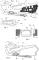
Figure 1 illustrates a side view of an exemplary embodiment of the first anchoring piece and the second anchoring piece of the present center console system, anchored to the floor of the passenger compartment of a vehicle, as well as an exemplary embodiment of the structural body not yet linked to said anchoring pieces, made up of a frame piece and an upper trim piece. -
Figure 2 illustrates an enlarged perspective view of the exemplary embodiment of the first anchoring piece ofFigure 1 . -
Figure 3 illustrates an enlarged rear view of the pivoting linkage means for the frame piece and the first anchoring piece ofFigure 1 . -
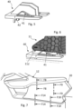
Figure 4 illustrates a side view of the exemplary embodiment of the center console system, wherein the center console already has the perimeter trim piece covering the structural body, but wherein the center console is not yet fixed to said first and second anchoring pieces. -
Figure 5 illustrates an enlarged view of the exemplary embodiment of the second anchoring piece ofFigure 1 or Figure 4 . -
Figure 6 illustrates an enlarged view of the spring linkage means of the structural body and the second anchoring piece ofFigure 1 , wherein the front portion of the structural body has been vertically displaced upwards by the pressure exerted by the second anchoring piece. -
Figure 7 illustrates a view of the present exemplary embodiment of the center console system in its use condition, wherein the center console is already fixed to said first and second anchoring pieces. -
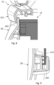
Figure 8 illustrates a longitudinal section view of detail F8 indicated inFigure 7 , showing the overlapping flange of the structural body and the overlapping flange of the perimeter trim piece. -
Figure 9 illustrates a longitudinal section view of detail F9 indicated inFigure 7 , showing transverse retention means for the frame piece and the perimeter trim piece. -
Figure 10 illustrates a longitudinal section view of detail F10 indicated inFigure 7 , showing the pivot means of the structural body and the perimeter trim piece of this exemplary embodiment. -
Figure 11 illustrates an enlarged side view of the pivot means of the perimeter trim piece ofFigure 10 . -
Figure 12 illustrates an enlarged side view of the pivot means of the frame piece ofFigure 10 . -
Figure 13 illustrates an enlarged side view of the vertical retention means of the perimeter trim piece. -
Figure 14 illustrates a longitudinal section view of detail F14 indicated inFigure 7 , showing the vertical retention means for the second anchoring piece and the perimeter trim piece. - In view of the aforementioned figures, and in accordance with the numbering used, an exemplary embodiment of the present center console system is described below.
-
Figure 1 illustrates an exemplary embodiment of the structural body (10) of the center console, that is, of the center console without the perimeter trim piece (20). In this embodiment, the structural body (10) is defined by a frame piece (11) and by an upper trim piece (12) mechanically linked to each other, such that both parts are displaced together. ThisFigure 1 also shows a portion of the dashboard (S), in the front part of the passenger compartment, as well as the first anchoring piece (30) and the second anchoring piece (40) already fixed to the floor of the passenger compartment of the vehicle. - In this embodiment, the upper trim piece (12) is configured to be fixed both to the dashboard (S) and to a spine (E) that protrudes from the dashboard (S). In any case, there is a mechanical linkage between the upper trim piece (12) and the dashboard (S), which requires contact between both components to cause said mechanical linkage.
- In turn, the frame piece (11) comprises two pivots (111) at its lower end, specifically, in the rear portion of said frame piece (11), one on each side and coaxial (visible in detail in
Figure 3 ), which extend outwards, that is, in opposite directions and in a direction perpendicular to the sagittal plane of the structural body (10), as pivotal linkage means suitable for being linked to the first anchoring piece (30). -
Figure 2 shows the first anchoring piece (30) of this embodiment in detail, which, in turn, comprises a guide (31) on each lateral side that extends in said longitudinal direction, as pivoting linkage means suitable for housing a respective pivot (111) of the frame piece (11). Both guides (31) are symmetrical with respect to the sagittal plane of the first anchoring piece (30). In turn, these guides (31) are defined by: - an access opening (311) the vertical dimension of which is greater than that of the pivots (111),
- an elongated slot (312) in said longitudinal direction, the vertical dimension of which is substantially equal to the dimensions of the pivots (111), so as to restrict the vertical displacement of the pivot (111) that is inserted in it, and
- a transition section the vertical dimension of which decreases from that of the access opening (311) to that of the elongated slot (312) as it extends longitudinally from the access opening (311) to said elongated slot (312).
- Therefore, the pivots (111) and the guides (31) are configured to be pivotally linked to each other, with the intention of allowing the structural body (10) to pivot in its sagittal plane with respect to the floor or dashboard of the vehicle. As can be seen in
Figure 3 , the pivots (111) are sized to form a single pivot axis, as well as to be inserted and slid through said guides (31), so that the pivoting linkage occurs in any of the positions of the pivots (111) in the respective guides (31). - As a result of the configuration of these pivoting linkage means, the linkage of the structural body (10) with the first anchoring piece (30) is facilitated, without requiring visual contact by the operator during the process of handling the structural body (10) with respect to the first anchoring piece (30). This is advantageous when the center console system comprises a perimeter trim piece (20) covering the frame piece (11), as depicted in
Figure 4 . - As mentioned, the present embodiment of the center console system also comprises a second anchoring piece (40) anchored to the floor of the passenger compartment. As can be seen in
Figure 5 , the second anchoring piece (40) comprises a cantilevered, pyramid-shaped semi-rigid flange (41), that is, provided with an oblique portion that forms a ramp, as spring linkage means. In turn, as can be seen inFigure 6 , the front part of the frame piece (11) comprises a rigid surface (112) at its lower end, as spring linkage means configured to collide with said semi-rigid flange (41) as the structural body (10) is displaced forward in its longitudinal displacement movement guided by the first anchoring piece (30). Given the ramp shape, the semi-rigid flange (41) exerts such vertical pressure that it deflects the front part of the frame piece (11) in an upward direction and keeps it vertically raised. In this way, in a single dragging movement by the operator of the structural body (10) of the center console, said longitudinal displacement being guided by the guides (31) of the first anchoring piece (30), an upward movement of the front portion of said center console occurs simultaneously, due to the vertical pushing generated by the contact between the semi-rigid tab (41) in the form of a ramp and the rigid surface (112). Said vertical displacement of the front portion of the center console is allowed by the rotational movement between the pivots (111) and the guides (31) in the rear portion of said center console. - As illustrated in
Figures 4 and7 , the center console also comprises a perimeter trim piece (20) configured to cover the perimeter part of the frame piece (11) that is not covered by the upper trim piece (12). ). As can be seen inFigure 8 , the upper trim piece (12) comprises an overlapping flange (121) arranged perimetrally and projecting downwards, generating a cavity suitable for housing a flange. In turn, the upper end of the perimeter trim piece (20) comprises an overlapping tab (201) projected upwards and sized to fit snugly on the inner side of said overlapping tab (121). Likewise, said overlapping tab (201) is vertically sized to remain, at least partially, inside the overlapping tab (121) in a wide vertical displacement range of the perimeter trim piece (20) with respect to the upper trim piece (12), while the perimeter trim piece (20) is sized to cover the frame piece (11) from the floor of the passenger compartment to the overlapping flange (121). Thus, in the event of an upward movement of the assembly formed by the frame (11) and the upper trim piece (12), the at least one perimeter trim piece (20) must remain in contact with the floor of the passenger compartment. Otherwise, it would generate a poor visual and aesthetic finish. To this end, the relative displacement in said vertical axis is allowed between the perimeter trim piece (20) and the upper trim piece (12) so that, in any of the relative displacement positions, the upper end of the overlapping piece ( 201) is covered by the overlapping tab (121), avoiding the generation of a slot, cavity, or gap in said area that generates a poor visual or aesthetic finish. - Also in this embodiment, the non-visible side of the perimeter trim piece (20) comprises several U-shaped transverse projections (202), as transverse retention means configured to retain tabs in the horizontal direction and perpendicular to said longitudinal direction, as depicted in
Figure 9 . In turn, the structural body (10), specifically its frame piece (11) in this embodiment, comprises inverse L-shaped transverse flanges (113). Said U-shaped transverse projections (202) are sized in height similar to the dimension of said overlapping tab (201), to have an equivalent tolerance in the vertical connection thereof, while they are sized in width to receive the transverse flanges (113) snugly therein in the transverse direction. In this way, they only block the relative movement of the perimeter trim piece (20) with respect to the structural body (10) in the transverse direction, while allowing relative movement in any direction within the plane perpendicular to said transverse direction. - Additionally, in this embodiment, each side of the rear part of the frame piece (11) comprises a rotation gap (114), as pivot means to guide a rotational movement of the perimeter trim piece (20), one of them shown in
Figures 10 and 12 , which extends in the transverse direction of the passenger compartment and defining an axis of rotation in said same transverse direction of the passenger compartment. At the same time, each non-visible side of the perimeter trim piece (20) comprises respective rotation pivots (203), as corresponding pivot means, one of them shown inFigures 10 and 11 . These rotation pivots (203) are configured to pivot around said rotation gap (114), allowing the perimeter trim piece (20) to pivot with respect to the structural body (10) in said sagittal plane. Said rotation gaps (114) and said rotation pivots (203) are arranged in a rear portion of, respectively, the frame piece (11) and the perimeter trim piece (20), linking both components according to a single degree of freedom, e.g., said rotation in the transverse direction of the passenger compartment. In this way, the front portion of both components is allowed to have said relative displacement with respect to each other, especially in the vertical direction, in order to offset the manufacturing and assembly tolerances of the assembly formed by the center console, the dashboard of the vehicle and the floor of the passenger compartment of the vehicle. - As can be seen in
Figures 4 and5 , the second anchoring piece (40) comprises a lower recess as a longitudinal guide (42). In turn, as can be seen inFigures 13 and 14 , the perimeter trim piece (20) comprises, on each non-visible side and in a position coinciding with said longitudinal guide (42) in its use condition, transverse pivots (204) as retaining means, capable of being retained under the longitudinal guide (42). In this way, the front part of the perimeter trim piece (20) does not separate from the floor, regardless of the position in which the frame piece (11) is located with respect to the floor. Specifically, the transverse pivots (204) of this embodiment comprise an inclined wall portion (205), configured to facilitate its placement in the longitudinal guide (42) while generating a downward displacement of the front part of the perimeter trim piece (20) when the structural body (10) is displaced forward, forcing said longitudinal guide (42) of the perimeter trim piece (20) to be located below the longitudinal guide (42) of the second anchoring piece (40). ). - The center console system of the present invention allows that, in the event of a dragging movement of the center console in a longitudinal displacement approaching the dashboard (S), a simultaneous movement of the front portion of said center console is generated such that it pivots and makes an upward movement so that the upper trim piece (12) contacts said dashboard (S), and a simultaneous movement of the front portion of the perimeter trim piece (20) is generated such that it pivots and makes a downward movement to contact the floor of the passenger compartment. In this way, it is ensured that there is contact between the center console, the floor of the passenger compartment and the dashboard (S) so that there is a mechanical linkage between them, but at the same time, no gaps or slots are generated between them that produce visual or aesthetic defects.
Claims (15)
- Center console system for vehicles of the type comprising a passenger compartment and a dashboard (S) at the front part of the passenger compartment, the center console system comprising:- a first anchoring piece (30) configured to be anchored to the floor of the passenger compartment,- a center console comprising a structural body (10), which is defined by a front portion and a rear portion, wherein the front portion is configured to be fixed to the dashboard (S),the center console system being characterized in that the first anchoring piece (30) and the rear portion of the structural body (10) comprise respective pivotal linkage means configured to be pivotally linked to each other, which allow the structural body (10) to pivot in its sagittal plane and, according to a pivoting movement, vertically displace the front portion of the structural body (10) for linking same with the dashboard (S).
- Center console system according to claim 1, wherein one of the pivoting linkage means comprise two guides (31) that extend in a longitudinal direction of the structural body (10) and the other pivotal linkage means comprise two coaxial pivots (111) that extend perpendicular to said longitudinal direction, sized to form a single pivot axis and slide through said guides (31), so that the pivoting linkage occurs in any of the positions of the pivots (111) in the respective guides (31).
- Center console system according to claim 2, wherein each guide (31) extends on a lateral side of the first anchoring piece (30), both guides (31) being symmetrical to each other according to said sagittal plane.
- Center console system according to claim 3, wherein each guide (31) defines an elongated slot (312) in said longitudinal direction, the height of said slot (312) being substantially equal to the dimensions of the respective pivot (111), such that the slots (312) restrict the vertical displacement of the pivots (111).
- Center console system according to claim 4, wherein at least one guide (31) comprises a funnel-shaped entry, provided with an access opening (311) the vertical dimension of which is greater than that of the respective pivot (111) and with a transition section the vertical dimension of which decreases from that of the access opening (311) to that of said elongated slot (312) as it extends longitudinally from the access opening (311) to said elongated slot (312).
- Center console system according to any of the preceding claims, comprising a second anchoring piece (40) configured to be anchored to the floor of the passenger compartment, wherein the front portion of the structural body (10) and the second anchoring piece (40) comprise respective spring linkage means suitable for being linked together, with a vertical pressure being exerted such that it generates an upward displacement of the front portion of the structural body (10) with respect to the floor of the passenger compartment.
- Center console system according to claim 6, wherein respective spring linkage means are configured to interlock with each other and deflect the front portion of the structural body (10) in an upward direction as the structural body (10) is displaced horizontally forward with respect to the floor of the passenger compartment.
- Center console system according to any of claims 6 to 7, wherein one of the spring linkage means comprise a semi-rigid flange (41) with at least one oblique portion forming a ramp and the other spring linkage means comprise a rigid surface (112).
- Center console system according to any of the preceding claims, wherein said at least one portion of the front portion of the structural body (10) configured to be fixed to the dashboard (S) is arranged at an upper end of the structural body (10).
- Center console system according to any of the preceding claims, wherein said at least one portion of the front portion of the structural body (10) configured to be fixed to the dashboard (S) is arranged at a front end of the structural body (10).
- Center console system according to any of the preceding claims, wherein the structural body comprises:- a frame piece (11), which is provided with one of said pivotal linkage means, and- at least one upper trim piece (12) mechanically linked to the frame piece (11) and covering at least an upper part thereof.
- Center console system according to claim 12, wherein the front portion of the frame piece (11) is configured for linking same with the dashboard (S).
- Assembly method carried out to assemble a center console system as described in any of the preceding claims in the passenger compartment of a vehicle with a dashboard, characterized in that it comprises the steps of:c) linking respective pivoting linkage means of the first anchoring piece (30) and of the structural body (10), andd) pivoting the structural body (10) in its sagittal plane until contacting the front portion of said structural body (10) with the dashboard (S) for linking same with said dashboard (S).
- Assembly method according to claim 13 of a center console system as described in claim 2, wherein step a) consists of placing the pivots (111) at the entry of respective guides (31) and pushing the structural body (10) by dragging it along the floor of the passenger compartment according to a longitudinal of the vehicle until contacting the front portion of the structural body (10) with the dashboard (S).
- Assembly method according to claim 14 carried out for a center console system as described in claim 6 or 7, wherein steps a) and b) are carried out simultaneously, the pivot movement being caused by the vertical pressure exerted by respective spring linkage means to each other.
Applications Claiming Priority (1)
| Application Number | Priority Date | Filing Date | Title |
|---|---|---|---|
| ES202230718A ES2960632B2 (en) | 2022-08-02 | 2022-08-02 | CENTER CONSOLE SYSTEM AND ASSEMBLY PROCEDURE |
Publications (1)
| Publication Number | Publication Date |
|---|---|
| EP4316914A1 true EP4316914A1 (en) | 2024-02-07 |
Family
ID=89473513
Family Applications (1)
| Application Number | Title | Priority Date | Filing Date |
|---|---|---|---|
| EP23188766.2A Pending EP4316914A1 (en) | 2022-08-02 | 2023-07-31 | Center console system and assembly method |
Country Status (2)
| Country | Link |
|---|---|
| EP (1) | EP4316914A1 (en) |
| ES (1) | ES2960632B2 (en) |
Citations (6)
| Publication number | Priority date | Publication date | Assignee | Title |
|---|---|---|---|---|
| EP0047858A1 (en) | 1980-09-12 | 1982-03-24 | Gebr. Happich GmbH | Modular unit for the interior area of a vehicle |
| US5106143A (en) | 1990-08-31 | 1992-04-21 | Prince Corporation | Snap-in floor console |
| EP2804782B1 (en) * | 2012-01-19 | 2015-12-09 | Peugeot Citroën Automobiles SA | Removable console for the inner space of a motor vehicle |
| US9308871B2 (en) | 2011-11-21 | 2016-04-12 | Lisa Draexlmaier Gmbh | Center console for vehicles and method for the production thereof |
| WO2020058143A1 (en) * | 2018-09-17 | 2020-03-26 | Motherson Innovations Company Ltd. | Center console between two vehicle seats and motor vehicle having a center console of this type |
| DE102021120041A1 (en) * | 2020-11-13 | 2022-05-19 | Hyundai Motor Company | PORTABLE RECORDING DEVICE |
-
2022
- 2022-08-02 ES ES202230718A patent/ES2960632B2/en active Active
-
2023
- 2023-07-31 EP EP23188766.2A patent/EP4316914A1/en active Pending
Patent Citations (6)
| Publication number | Priority date | Publication date | Assignee | Title |
|---|---|---|---|---|
| EP0047858A1 (en) | 1980-09-12 | 1982-03-24 | Gebr. Happich GmbH | Modular unit for the interior area of a vehicle |
| US5106143A (en) | 1990-08-31 | 1992-04-21 | Prince Corporation | Snap-in floor console |
| US9308871B2 (en) | 2011-11-21 | 2016-04-12 | Lisa Draexlmaier Gmbh | Center console for vehicles and method for the production thereof |
| EP2804782B1 (en) * | 2012-01-19 | 2015-12-09 | Peugeot Citroën Automobiles SA | Removable console for the inner space of a motor vehicle |
| WO2020058143A1 (en) * | 2018-09-17 | 2020-03-26 | Motherson Innovations Company Ltd. | Center console between two vehicle seats and motor vehicle having a center console of this type |
| DE102021120041A1 (en) * | 2020-11-13 | 2022-05-19 | Hyundai Motor Company | PORTABLE RECORDING DEVICE |
Also Published As
| Publication number | Publication date |
|---|---|
| ES2960632A1 (en) | 2024-03-05 |
| ES2960632B2 (en) | 2024-07-10 |
Similar Documents
| Publication | Publication Date | Title |
|---|---|---|
| EP1411598B1 (en) | A connector assembly, connector, connector assembling construction and method of assembling them | |
| US7481596B2 (en) | Connector which is used to join a windscreen wiper arm to a wiper blade | |
| CN110011197B (en) | Power distribution box assembly with alignment features | |
| JPH0917505A (en) | Connector assembly with mating assurance device, connector used therefor, and mating assurance device thereof | |
| JPH0973950A (en) | Movable connector | |
| EP0881972B1 (en) | Self-aligning connection system | |
| EP0800237B1 (en) | Structure of interconnecting units with respective connectors | |
| EP1096617A1 (en) | A connector mounting construction, a connector and a holder therefor | |
| EP0998770B1 (en) | Self docking instrument panel connector system | |
| EP1710869B1 (en) | A connector device | |
| CN114714997A (en) | seat rail assembly | |
| EP4316917A1 (en) | Center console and assembly method | |
| EP1168522B1 (en) | Connector with cam holder | |
| JP2002293175A (en) | Child seat | |
| JP2019077267A (en) | On-vehicle component fitting structure | |
| GB2374988A (en) | Improvements in and relating to socket outlets for plugs | |
| US7338317B1 (en) | Panel-mounted connector | |
| US6012947A (en) | Connector with semi-automatic coupling accompanying a mechanical coupling | |
| ES2960632B2 (en) | CENTER CONSOLE SYSTEM AND ASSEMBLY PROCEDURE | |
| US6322389B1 (en) | Connection assurance bracket system | |
| JP2002517349A (en) | Vehicle mirror | |
| US20030114038A1 (en) | Connector construction and a method for connecting a pair of connectors | |
| CN115123102B (en) | Vehicle display screen bracket and vehicle | |
| US20250304172A1 (en) | Vehicle rear fascia assembly | |
| JP2004111265A (en) | Connector |
Legal Events
| Date | Code | Title | Description |
|---|---|---|---|
| PUAI | Public reference made under article 153(3) epc to a published international application that has entered the european phase |
Free format text: ORIGINAL CODE: 0009012 |
|
| STAA | Information on the status of an ep patent application or granted ep patent |
Free format text: STATUS: THE APPLICATION HAS BEEN PUBLISHED |
|
| AK | Designated contracting states |
Kind code of ref document: A1 Designated state(s): AL AT BE BG CH CY CZ DE DK EE ES FI FR GB GR HR HU IE IS IT LI LT LU LV MC ME MK MT NL NO PL PT RO RS SE SI SK SM TR |
|
| STAA | Information on the status of an ep patent application or granted ep patent |
Free format text: STATUS: REQUEST FOR EXAMINATION WAS MADE |
|
| 17P | Request for examination filed |
Effective date: 20240729 |
|
| RBV | Designated contracting states (corrected) |
Designated state(s): AL AT BE BG CH CY CZ DE DK EE ES FI FR GB GR HR HU IE IS IT LI LT LU LV MC ME MK MT NL NO PL PT RO RS SE SI SK SM TR |
|
| GRAP | Despatch of communication of intention to grant a patent |
Free format text: ORIGINAL CODE: EPIDOSNIGR1 |
|
| STAA | Information on the status of an ep patent application or granted ep patent |
Free format text: STATUS: GRANT OF PATENT IS INTENDED |
|
| INTG | Intention to grant announced |
Effective date: 20260114 |
|
| GRAS | Grant fee paid |
Free format text: ORIGINAL CODE: EPIDOSNIGR3 |
|
| GRAA | (expected) grant |
Free format text: ORIGINAL CODE: 0009210 |
|
| STAA | Information on the status of an ep patent application or granted ep patent |
Free format text: STATUS: THE PATENT HAS BEEN GRANTED |