EP4316907A1 - Lift frame assembly - Google Patents
Lift frame assembly Download PDFInfo
- Publication number
- EP4316907A1 EP4316907A1 EP23168729.4A EP23168729A EP4316907A1 EP 4316907 A1 EP4316907 A1 EP 4316907A1 EP 23168729 A EP23168729 A EP 23168729A EP 4316907 A1 EP4316907 A1 EP 4316907A1
- Authority
- EP
- European Patent Office
- Prior art keywords
- lift frame
- load carrying
- carrying object
- connecting structure
- frame assembly
- Prior art date
- Legal status (The legal status is an assumption and is not a legal conclusion. Google has not performed a legal analysis and makes no representation as to the accuracy of the status listed.)
- Granted
Links
Images
Classifications
-
- B—PERFORMING OPERATIONS; TRANSPORTING
- B60—VEHICLES IN GENERAL
- B60P—VEHICLES ADAPTED FOR LOAD TRANSPORTATION OR TO TRANSPORT, TO CARRY, OR TO COMPRISE SPECIAL LOADS OR OBJECTS
- B60P1/00—Vehicles predominantly for transporting loads and modified to facilitate loading, consolidating the load, or unloading
- B60P1/64—Vehicles predominantly for transporting loads and modified to facilitate loading, consolidating the load, or unloading the load supporting or containing element being readily removable
- B60P1/6418—Vehicles predominantly for transporting loads and modified to facilitate loading, consolidating the load, or unloading the load supporting or containing element being readily removable the load-transporting element being a container or similar
- B60P1/6463—Vehicles predominantly for transporting loads and modified to facilitate loading, consolidating the load, or unloading the load supporting or containing element being readily removable the load-transporting element being a container or similar fitted with articulated beams for longitudinal displacement of the container
Definitions
- the present disclosure relates to a lift frame assembly for a working equipment arranged to load and unload a load carrying object, e.g. a container, to/from a vehicle, by using a lift frame being attachable to the working equipment, and in particular lift frames adapted to load handling of ISO containers.
- a load carrying object e.g. a container
- a lift frame being attachable to the working equipment, and in particular lift frames adapted to load handling of ISO containers.
- Lift frames are typically used together with a working equipment having a movable arm, such as hook lifts, to load and unload load carrying objects, such as containers, or more specifically ISO containers.
- Many types of containers are provided with connecting portions having openings or cavities at the corners of the container structure to enable efficient and safe locking to a lift frame and hence a working equipment used to load and unload the containers to/from vessels or vehicles used for transport, or when rearranging containers at e.g. ports, industries or logistics centres.
- a container is conventionally in the form of a parallelepiped box, intended for transporting goods.
- the International Organization for Standardization defines standards for containers, in particular of dimensions (length, width, height), mass, or configurations (disposition of orifices allowing the container to be gripped, etc.). Due to standardisation of the containers, the ISO standard facilitates handling thereof. For the purpose of transporting goods, the ISO containers have to be moved and lifted, for loading and unloading on various vehicles, for example trucks or boats.
- Handling of an ISO container for example in port installations, is conventionally carried out by means of a container lifting system using container spreaders engaging in orifices in the four corners of the upper face of the container, the upper face being the face opposite the face placed on the ground.
- the container spreader then locks to the container, for example by means of rotating locks.
- This type of container lifting system with spreaders may be used to load or unload the container to or from a vehicle.
- Handling of an ISO container can also be carried out by means of a lifting system engaging in orifices formed in the four corners of a vertical front face or rear face of the container, the front and opposite rear face (or wall) corresponding to a face of smaller dimensions of the container.
- the vertical walls with longer horizontal dimensions are often referred to as side walls.
- Load-handling vehicles are trucks which are conceived as carrier vehicles for transporting load carrying objects such as containers. Examples of such load-handling vehicles are roll-on/roll-off dump trucks or hook-lift trucks. Load-handling vehicles may hence be equipped with a working equipment comprising a loading arm assembly to be able to load and unload a container to or from the vehicle by itself.
- ISO standard 668 forms the respective standard for said ISO containers.
- the ISO standard 668 comprises, among others, 1C, 1CC and 1CX containers, each having different heights.
- the ISO containers are gripped by the corners, and a correspondingly configured loading arm assembly has at least two corner grippers, wherein the corner grippers can grip the ISO container at the corners.
- a loading arm assembly may have a main arm, wherein the main arm is disposed so as to be pivotable on the vehicle chassis.
- an auxiliary arm configured so as to be elbow-shaped, is disposed on the main arm.
- the auxiliary arm may be disposed on the main arm by an articulated joint, a telescopic arrangement or a fixed mounting.
- a gripping hook is configured on the free end of the articulated arm.
- a lift frame having four corner grippers can be attached to the elbow-shaped region of the articulated arm, so as to thus be able to also load and unload ISO containers. The lift frame when not in use can be unloaded onto the load-handling vehicle behind the cab.
- Old lift frame designs have typically a manual locking to the container with manually inserted and secured pins.
- solutions including automatic, and semi-automatic locking capabilities, see e.g. WO2021/255345 .
- EP3838666A1 relates a lifting support for a container, comprising two upper pins and two lower pins, adapted to be inserted into complementary holes of the container when the lifting support is in a first position vis-à-vis the container two intermediate pins, positioned between the two upper pins and the two lower pins, and adapted to be inserted into two upper complementary openings of the container when the lifting support is in a second position vis-à-vis the container.
- JP2020104768A relates to a container handling vehicle comprising a chassis on which standard containers are loaded; a handling arm, which has a hook at a tip thereof, is provided on an upper part of the chassis so as to be rotatable forward and backward, and performs a handling operation for standard containers; an adapter which is installed on the standard container and is used for the handling operation; a stand table which supports the adapter on the chassis, and a control unit which controls the handling arm.
- WO2020/174265A1 relates to a container handling device that can be installed on a vehicle, the device being configured for attaching a front end of a container placed in front of a rear end of a loading surface the vehicle.
- the object of the present invention is to achieve an improved lift frame assembly that in particular is adapted to be used for automatic or semi-automatic operations, specifically to provide secure, robust and reliable operations that require less manual intervention than presently applied systems.
- all the connecting structures are configured to be controlled to be in the fully retracted position range during an alignment process when aligning the lift frame to the load carrying object in order to proceed with the loading by locking the lift frame to the load carrying object.
- all connecting structures are in their fully retracted position ranges, none of them will interfere with the load carrying object during an attachment procedure.
- the arrangement of the connecting structures according to the invention allows for a certain margin in the lateral alignment while the connecting structures are in their fully retracted position ranges.
- a further advantage with the lift frame assembly according to the invention is that it offers a robust and rigid locking of the lift frame to the load carrying object in a closed position, without adding width outside what standards and regulations allow when the load carrying object is loaded to a vehicle.
- the robust and rigid, but yet space efficient, locking of the lift frame is accomplished through e.g. the fact that the pivot axis of the connecting structure is being parallel to a vertical symmetry axis S of the lift frame. This enables for the length of the connecting structure to extend in the vertical direction along this pivot axis and thereby create a robust and rigid connection between the lift frame and the load carrying object when in a closed position, without the need for adding thickness to the connecting structure for the robustness.
- the robustness of the locking in a closed position of the connecting structure will be further improved as the connecting structure will be supported by the transversal side of the lift frame. This will further also support the alignment of the lift frame to the load carrying object.
- the alignment process is improved as in one example, where the upper connectors are initially attached to the load carrying object. This may be performed even if the vertical orientation of the symmetry axis S of the lift frame does not coincide with the vertical side walls of the load carrying object, because, the connecting structures, when in their fully retracted ranges, will not interfere with the load carrying object, in particular the side of the load carrying object facing the lift frame, as they are below the planar virtual contact plane.
- the connecting structures may assist in aligning the lift frame to the side walls of the load carrying object when the connecting structures are moved around their pivot axes towards the closed position.
- One advantage obtained by the present invention for a driver, operating the loading of e.g. an ISO container to a truck, is that the whole loading operation may be operated from the truck cabin where the driver is in a protected environment, while still allowing a margin of mismatch in the lateral alignment of the lift frame to the container, where the connecting structures will be able to correct the mismatch when being controlled to move in the direction towards the locked position, either manually, semi-automatically, or fully automatically.
- the lift frame assembly according to the present invention is particularly beneficial to use when a load carrying object is positioned on a slope in uneven terrain and specifically when a vehicle, provided with a working equipment and the lift frame assembly, is in an inclined position in relation to the position of the load carrying object.
- the lift frame assembly defined by the appended claims includes the new solution for the corner connectors, also referred to as grippers, which is the focus of the present invention, and which are structured to be used together with a working equipment for loading and unloading load carrying objects to and from a vehicle.
- the working equipment 2 comprises a movable arm 6 for loading and unloading a load carrying object 8, such as a container, to/from the vehicle 4.
- the movable arm 6 has a first end 10 connected to the vehicle and a second end 12 arranged to connect the movable arm 6 to the load carrying object 8 during the loading or unloading.
- the working equipment 2 further comprises a lift frame assembly 14 comprising hydraulic and/or electrical actuators 44 arranged to operate the pivoting movements of connecting structures 51 (see figures 5-10 ), which will be further described below, an actuator system 32, and further a sensor system 34 provided to monitor the movements of the working equipment 2 and the lift frame 16.
- a control unit 36 is provided configured to generate control instructions 38 to control the operation of the actuator system 32 in response to a loading/unloading command 40 for the loading and/or unloading of the load carrying object 8 and sensor signals 42 received from the sensor system 34.
- Hoses for a possible hydraulic system and/or electrical cables for electric actuators and/or sensors may be guided from the vehicle and/or working equipment to the lift frame assembly via the movable arm.
- the set of actuators 44 comprises actuators configured to change the positions of upper connectors 20 relative to an attachment part 18 along parallel movement axes M, when the working equipment is configured to perform an attachment procedure, i.e. a procedure for attaching the lift frame to the load carrying object.
- the control unit 36 is further configured to generate instructions 46 to control the set of actuators 44 to change the positions of the upper connectors 20 along the movement axes M during an attachment procedure for attaching the lift frame 16 to the load carrying object 8 in response of an attachment command 48, and sensor signals 42 from the sensor system 34.
- the instructions 46 may then include instructions to change the positions of the upper connectors 20, and/or also instructions to perform the actual attachments of these connectors to the load carrying object during an attachment procedure.
- the set of actuators 44 are preferably provided with position sensors, which may be applied to adjust the distance between upper and lower connectors to correspond to the dimension of the load carrying object.
- the unloading and/or loading with the lift frame together with a working equipment and vehicle are preferably part of an autonomous or semiautonomous loading sequence.
- a lift frame assembly 14 is provided, for a working equipment 2 arranged to load and unload a load carrying object 8 to/from a vehicle 4.
- the lift frame assembly 14 comprises a lift frame 16 arranged to connect the working equipment 2 to the load carrying object 8 during loading and unloading to/from the vehicle 4.
- the lift frame 16 has a rear side 55 arranged towards the working equipment 2, a front side 56 arranged to face the load carrying object 8, during the loading and unloading, and a set of connectors 20, 24 mounted to the lift frame 16 that is further arranged to lock the lift frame 16 to corresponding connecting portions 28, 30 of the load carrying object 8 during loading and unloading to/from the vehicle 4.
- Each of at least two of the connectors of the set of connectors 20, 24 comprises a connecting structure 51 arranged to pivot around a pivot axle, having a longitudinal extension along a pivot axis 57, between a closed position wherein the lift frame 16 is arranged to be locked to the load carrying object 8 and a retracted position range wherein the lift frame 16 is not locked to the load carrying object 8.
- the pivot axis 57 being parallel to a vertical symmetry axis S (see figure 3 ) of the lift frame.
- FIGS 3 and 4 are shown movement axes M illustrating movement directions of the set of connectors, according to one example of an embodiment of the invention.
- Each connecting structure 51 comprises a locking protrusion 52 (see figures 7-10 ) arranged to engage with a corresponding cavity at a connection portion 28, 30 of the load carrying object 8 to lock, when in the closed position, the lift frame 16 to the load carrying object 8.
- the connecting structure also comprises an actuator 53 arranged to operate the pivoting movement of the connecting structure 51 between the closed position and the retracted position range by moving the connecting structure 51 around the pivot axis 57.
- the connecting structure 51 when the connecting structure 51 is in the retracted position range, the connecting structure 51 is arranged to be pivoted into a fully retracted position range, being a position range where no part of the connecting structure 51 extends beyond a planar virtual contact plane V defined by load carrying object contacting surfaces of the front side 56 of the lift frame 16 in the direction of the load carrying object 8.
- Figures 7-10 are schematic views from above of one side ( figures 7 and 8 ) and of both sides ( figures 9 and 10 ) of a part of the lift frame 16 where the connecting structure 51 is arranged, and where the planar virtual contact plane V is shown as dashed lines.
- FIGS 7 and 9 the connecting structure 51 is in its fully retracted position range, i.e. in a position range where no part extends beyond the virtual contact plane V, and thereby not will interfere with any part of the load carrying object 8 during an alignment procedure.
- Figures 8 and 10 show the connecting structure moved into a closed position wherein it is arranged for locking the lift frame to the load carrying object.
- the connecting structure 51 comprises a pivoting arm 58 having a first end connected to a pivot axle which is directed along said pivot axis 57, and a second end where the locking protrusion 52 is provided.
- the pivoting arm 58 In the closed position, see figure 8 , the pivoting arm 58 is configured to extend essentially perpendicular to the front side 56 of the lift frame 16 in the direction of the load carrying object 8, and in said retracted position range, see figure 7 , the pivoting arm 58 is arranged to perform its pivoting movement in a movement space beyond a plane defined by a transversal side 54 of the lift frame 16.
- the transversal side 54 has an extension essentially perpendicular to the rear side 55 and the front side 56 of the lift frame 16.
- the pivot axis 57 is aligned with the transversal side 54 of the lift frame 16, and that the transversal side has an extension essentially perpendicular to said rear side 55 and front side 56 of the lift frame 16.
- the pivot axis 57 is aligned with the rear side 55 of the lift frame.
- the extension of the transversal side 54 will in this embodiment further support the position of the connecting structure 51 in its closed position enabling a robust and rigid locking of the lift frame to the load carrying object and further to support the alignment of the lift frame to the load carrying object.
- the actuator 53 is a linear actuator, which may e.g. be hydraulically, or electrically, operated.
- the pivot axis 57 is aligned with the rear side 55 of the lift frame 16, and that the actuator 53 is a linear actuator, and that the linear actuator is attached to the lift frame 16 close to the front side 56 of the lift frame 16, and configured to apply pivotal movement to the connecting structure 51 by applying pushing and/or pulling linear forces to a pivoting arm 58 of the connecting structure 51.
- This embodiment is illustrated by figures 7 and 8 .
- pivot axis 57 at a distance to the front wall of the load carrying object, i.e. closer to the rear side 55 of the lift frame than the front side 56 of the lift frame, and in a vertically orientation with reference to the vertical side walls of the load carrying object.
- One advantage is that it allows for a connection to the linear actuator 53 which may be attached to inner parts of the lift frame 16 and is thereby protected from outside manipulation, and another advantage is that the connecting structure will be operated with a pulling force when moved to the closed position, which results in an advantageous use of the applied movement energy.
- the actuator 53 instead is a torsional actuator configured to apply torsional movement to a pivot axle, directed along the pivot axis 57, of the connecting structure 51.
- the pivot axis 57 is hence arranged in a plane of the rear side 55 of the lift frame, or in its close proximity. In a preferred embodiment the pivot axis 57 is arranged to be parallel to the vertical sides of the load carrying object 8 during loading and unloading.
- pivot axis 57 may be arranged in the plane of the transversal side 55 of the lift frame, at any position between the rear side 55 and the front side 56 which is generally illustrated by the schematic illustrations shown in figures 9 and 10 .
- the connecting structure 51 is in its fully retracted position range, and in figure 6 the connecting structure 51 is in its closed position.
- the connecting structure illustrated therein has an essentially triangular shape along the pivoting arm from the pivot axis 57 to the locking protrusion 52. It is advantageous that the connecting structure 51 has a certain surface area that extends from the pivot axis to the locking protrusion as it may then be used during an alignment procedure to gently guide, during movement of the connecting structure, the load carrying object into a position where the locking protrusion may be inserted into a mating connector cavity of the load carrying object.
- the size and shape of the connecting structure may naturally vary, e.g.
- the lift frame 16 is provided with an attachment part 18 that may be in the shape of a bar adapted to engage with a hook at the second end 12 of the movable arm 6.
- This type of attachment provides a releasable connection between the parts that further allows for the lift frame assembly to pivot around the connection point.
- This type of attachment may further allow the lift frame assembly to be horizontally aligned when it is free-hanging at the hook.
- attachment part 18 and the second end 12 are further possible that would provide a similar releasable and pivoting connection.
- a non-releasable attachment between the attachment part 18 and the second end 12 may be provided.
- the lift frame 16 has preferably the shape of the letter "H" with two vertical side structures that a set of actuators 44 that is configured to change the positions of the upper connectors may be mounted to.
- a structure connecting, or linking, these two vertical side structures are further part of the lift frame in the H-shaped embodiment.
- the attachment part 18 may further be arranged at this connecting, or linking, structure in this embodiment.
- An alternative to the "H" shape of the lift frame 16 may however be an "X" shape.
- a rear side of the lift frame 16 faces the working equipment and the attachment part 18 is hence accessible from the rear side, while the front side of the lift frame 16 is directed towards the load carrying object 8.
- the H-shape is advantageous in that it provides a structure and symmetry of the lift frame that results in a natural horizontal levelling when the lift frame is hanging free at the second end 12 of the movable arm.
- the vertical side structures may further be arranged to at least partly cover and protect the actuators 44.
- the lift frame as illustrated in figure 3 has essentially the shape of the capital letter H.
- the set of connectors comprises a pair of upper connectors 20 mounted at opposite sides of an upper part 22 of the lift frame 16, and a pair of lower connectors 24 mounted at opposite sides of a lower part 26 of the lift frame 16, and that each of the lower connectors 24 comprises one connecting structure 51.
- the connectors, or grippers are in the figures shown as pairs of upper and lower connectors 20, 24 which are adapted to attach the upper and lower parts 22, 26 of the lift frame 16 to a corresponding upper part 28 and lower part 30, respectively, of the load carrying object 8.
- the upper and lower parts of the load carrying object are provided with openings/orifices according to a specified standard, where the connectors of the lift frame will attach and lock in order to perform a loading/unloading procedure.
- the upper connectors 20, and the lower connectors 24, may be of the same type or may alternatively be specifically adapted to e.g. the locking to the upper or lower portion of the load carrying object 8.
- the connectors' movements are operated by actuators, e.g. electrical or hydraulic actuators, so that there is no need for the operator to get out of the cabin during this operation.
- the front side of the lift frame i.e. the side of the lift frame facing the load carrying object during use, is provided with surfaces intended to be in physical contact with the vertical front face or rear face of the load carrying object when the lift frame is connected to the load carrying object.
- the plane defined by these contact surfaces defines the planar virtual contact plane V.
Landscapes
- Engineering & Computer Science (AREA)
- Transportation (AREA)
- Mechanical Engineering (AREA)
- Forklifts And Lifting Vehicles (AREA)
Abstract
Description
- The present disclosure relates to a lift frame assembly for a working equipment arranged to load and unload a load carrying object, e.g. a container, to/from a vehicle, by using a lift frame being attachable to the working equipment, and in particular lift frames adapted to load handling of ISO containers.
- Lift frames are typically used together with a working equipment having a movable arm, such as hook lifts, to load and unload load carrying objects, such as containers, or more specifically ISO containers. Many types of containers are provided with connecting portions having openings or cavities at the corners of the container structure to enable efficient and safe locking to a lift frame and hence a working equipment used to load and unload the containers to/from vessels or vehicles used for transport, or when rearranging containers at e.g. ports, industries or logistics centres.
- A container is conventionally in the form of a parallelepiped box, intended for transporting goods. The International Organization for Standardization (ISO) defines standards for containers, in particular of dimensions (length, width, height), mass, or configurations (disposition of orifices allowing the container to be gripped, etc.). Due to standardisation of the containers, the ISO standard facilitates handling thereof. For the purpose of transporting goods, the ISO containers have to be moved and lifted, for loading and unloading on various vehicles, for example trucks or boats.
- Handling of an ISO container, for example in port installations, is conventionally carried out by means of a container lifting system using container spreaders engaging in orifices in the four corners of the upper face of the container, the upper face being the face opposite the face placed on the ground. The container spreader then locks to the container, for example by means of rotating locks. This type of container lifting system with spreaders may be used to load or unload the container to or from a vehicle. Handling of an ISO container can also be carried out by means of a lifting system engaging in orifices formed in the four corners of a vertical front face or rear face of the container, the front and opposite rear face (or wall) corresponding to a face of smaller dimensions of the container. For clarity it may be noted that the vertical walls with longer horizontal dimensions are often referred to as side walls.
- Load-handling vehicles are trucks which are conceived as carrier vehicles for transporting load carrying objects such as containers. Examples of such load-handling vehicles are roll-on/roll-off dump trucks or hook-lift trucks. Load-handling vehicles may hence be equipped with a working equipment comprising a loading arm assembly to be able to load and unload a container to or from the vehicle by itself.
- Furthermore, there are loading arm assemblies with lift frames which can receive a so-called ISO container. ISO standard 668 forms the respective standard for said ISO containers. The ISO standard 668 comprises, among others, 1C, 1CC and 1CX containers, each having different heights. The ISO containers are gripped by the corners, and a correspondingly configured loading arm assembly has at least two corner grippers, wherein the corner grippers can grip the ISO container at the corners.
- In known solutions, such as for a hook-lift, a loading arm assembly may have a main arm, wherein the main arm is disposed so as to be pivotable on the vehicle chassis. In turn, an auxiliary arm, configured so as to be elbow-shaped, is disposed on the main arm. The auxiliary arm may be disposed on the main arm by an articulated joint, a telescopic arrangement or a fixed mounting. Often a gripping hook is configured on the free end of the articulated arm. A lift frame having four corner grippers can be attached to the elbow-shaped region of the articulated arm, so as to thus be able to also load and unload ISO containers. The lift frame when not in use can be unloaded onto the load-handling vehicle behind the cab.
- Old lift frame designs have typically a manual locking to the container with manually inserted and secured pins. There are also solutions including automatic, and semi-automatic locking capabilities, see e.g.
WO2021/255345 . - Thus, this reflects an important aspect of the technical field that comprises moving towards automatic functionality where operators can remain in the cabin during the whole operation, which requires a new approach, and raises demands for new technical solutions. Currently available solutions are often provided with a pivoting axis of the corner connections (sometimes also referred to as corner grippers or locks) being arranged along a lateral side of the frame (perpendicular to the plane in which the lift frame is extended in). These solutions are often problematic for the alignment of the lift frame to the container as there is only a small margin when it comes to lateral, side to side, alignment of the lift frame to the container. This in turn will put high requirements on the operator of the vehicle with the working equipment to align the vehicle to the container.
- In the following some related prior art documents will be identified and briefly discussed.
EP3838666A1 relates a lifting support for a container, comprising two upper pins and two lower pins, adapted to be inserted into complementary holes of the container when the lifting support is in a first position vis-à-vis the container two intermediate pins, positioned between the two upper pins and the two lower pins, and adapted to be inserted into two upper complementary openings of the container when the lifting support is in a second position vis-à-vis the container. -
JP2020104768A WO2020/174265A1 relates to a container handling device that can be installed on a vehicle, the device being configured for attaching a front end of a container placed in front of a rear end of a loading surface the vehicle. - The object of the present invention is to achieve an improved lift frame assembly that in particular is adapted to be used for automatic or semi-automatic operations, specifically to provide secure, robust and reliable operations that require less manual intervention than presently applied systems.
- The above-mentioned objects are achieved by the present invention according to the independent claims.
- Preferred embodiments are set forth in the dependent claims.
- In one aspect of the lift frame assembly according to the present invention, all the connecting structures are configured to be controlled to be in the fully retracted position range during an alignment process when aligning the lift frame to the load carrying object in order to proceed with the loading by locking the lift frame to the load carrying object. When all connecting structures are in their fully retracted position ranges, none of them will interfere with the load carrying object during an attachment procedure.
- Thus, the arrangement of the connecting structures according to the invention allows for a certain margin in the lateral alignment while the connecting structures are in their fully retracted position ranges.
- A further advantage with the lift frame assembly according to the invention is that it offers a robust and rigid locking of the lift frame to the load carrying object in a closed position, without adding width outside what standards and regulations allow when the load carrying object is loaded to a vehicle. The robust and rigid, but yet space efficient, locking of the lift frame is accomplished through e.g. the fact that the pivot axis of the connecting structure is being parallel to a vertical symmetry axis S of the lift frame. This enables for the length of the connecting structure to extend in the vertical direction along this pivot axis and thereby create a robust and rigid connection between the lift frame and the load carrying object when in a closed position, without the need for adding thickness to the connecting structure for the robustness.
- In addition; by aligning the pivot axis with the rear side of the lift frame, such as outlined in further embodiment of the invention, the robustness of the locking in a closed position of the connecting structure will be further improved as the connecting structure will be supported by the transversal side of the lift frame. This will further also support the alignment of the lift frame to the load carrying object.
- The alignment process is improved as in one example, where the upper connectors are initially attached to the load carrying object. This may be performed even if the vertical orientation of the symmetry axis S of the lift frame does not coincide with the vertical side walls of the load carrying object, because, the connecting structures, when in their fully retracted ranges, will not interfere with the load carrying object, in particular the side of the load carrying object facing the lift frame, as they are below the planar virtual contact plane.
- In addition, during the attachment procedure, the connecting structures may assist in aligning the lift frame to the side walls of the load carrying object when the connecting structures are moved around their pivot axes towards the closed position.
- One advantage obtained by the present invention, for a driver, operating the loading of e.g. an ISO container to a truck, is that the whole loading operation may be operated from the truck cabin where the driver is in a protected environment, while still allowing a margin of mismatch in the lateral alignment of the lift frame to the container, where the connecting structures will be able to correct the mismatch when being controlled to move in the direction towards the locked position, either manually, semi-automatically, or fully automatically.
- The lift frame assembly according to the present invention is particularly beneficial to use when a load carrying object is positioned on a slope in uneven terrain and specifically when a vehicle, provided with a working equipment and the lift frame assembly, is in an inclined position in relation to the position of the load carrying object.
-
-
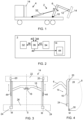
Figure 1 is a simplified illustration of a working equipment mounted to a vehicle and provided with a lift frame assembly. -
Figure 2 is a block diagram of the working equipment according to the present invention. -
Figures 3 and 4 show front and side views of the lift frame assembly according to the present invention. -
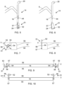
Figures 5 and 6 are schematic illustrations of a side view of a lift frame assembly according to embodiments of the present invention showing two different stages of the operation. -
Figures 7 and 8 are schematic illustrations according to embodiments of the present invention showing the connecting structure in two different stages of the operation. -
Figures 9 and 10 are schematic and simplified illustrations showing embodiments of the connecting structures in two different stages of the operation. - The lift frame assembly, a working equipment comprising the lift frame assembly and a vehicle provided with the working equipment, will now be described in detail with references to the appended figures. Throughout the figures the same, or similar, items have the same reference signs. Moreover, the items and the figures are not necessarily to scale, emphasis instead being placed upon illustrating the principles of the invention.
- The lift frame assembly, defined by the appended claims includes the new solution for the corner connectors, also referred to as grippers, which is the focus of the present invention, and which are structured to be used together with a working equipment for loading and unloading load carrying objects to and from a vehicle.
- First, with references to
figures 1-4 , a workingequipment 2 arranged to be mounted to avehicle 4, will be described in detail. - The working
equipment 2 comprises amovable arm 6 for loading and unloading aload carrying object 8, such as a container, to/from thevehicle 4. Themovable arm 6 has afirst end 10 connected to the vehicle and asecond end 12 arranged to connect themovable arm 6 to theload carrying object 8 during the loading or unloading. - The working
equipment 2 further comprises alift frame assembly 14 comprising hydraulic and/orelectrical actuators 44 arranged to operate the pivoting movements of connecting structures 51 (seefigures 5-10 ), which will be further described below, anactuator system 32, and further asensor system 34 provided to monitor the movements of the workingequipment 2 and thelift frame 16. Acontrol unit 36 is provided configured to generatecontrol instructions 38 to control the operation of theactuator system 32 in response to a loading/unloading command 40 for the loading and/or unloading of theload carrying object 8 and sensor signals 42 received from thesensor system 34. Hoses for a possible hydraulic system and/or electrical cables for electric actuators and/or sensors may be guided from the vehicle and/or working equipment to the lift frame assembly via the movable arm. - Preferably, the set of
actuators 44 comprises actuators configured to change the positions ofupper connectors 20 relative to anattachment part 18 along parallel movement axes M, when the working equipment is configured to perform an attachment procedure, i.e. a procedure for attaching the lift frame to the load carrying object. Thecontrol unit 36 is further configured to generateinstructions 46 to control the set ofactuators 44 to change the positions of theupper connectors 20 along the movement axes M during an attachment procedure for attaching thelift frame 16 to theload carrying object 8 in response of anattachment command 48, and sensor signals 42 from thesensor system 34. Theinstructions 46 may then include instructions to change the positions of theupper connectors 20, and/or also instructions to perform the actual attachments of these connectors to the load carrying object during an attachment procedure. - The set of
actuators 44 are preferably provided with position sensors, which may be applied to adjust the distance between upper and lower connectors to correspond to the dimension of the load carrying object. - The unloading and/or loading with the lift frame together with a working equipment and vehicle are preferably part of an autonomous or semiautonomous loading sequence.
- Thus, a
lift frame assembly 14 is provided, for a workingequipment 2 arranged to load and unload aload carrying object 8 to/from avehicle 4. Referring also tofigures 5-10 , thelift frame assembly 14 comprises alift frame 16 arranged to connect the workingequipment 2 to theload carrying object 8 during loading and unloading to/from thevehicle 4. Thelift frame 16 has arear side 55 arranged towards the workingequipment 2, afront side 56 arranged to face theload carrying object 8, during the loading and unloading, and a set ofconnectors lift frame 16 that is further arranged to lock thelift frame 16 to corresponding connectingportions load carrying object 8 during loading and unloading to/from thevehicle 4. - Each of at least two of the connectors of the set of
connectors structure 51 arranged to pivot around a pivot axle, having a longitudinal extension along apivot axis 57, between a closed position wherein thelift frame 16 is arranged to be locked to theload carrying object 8 and a retracted position range wherein thelift frame 16 is not locked to theload carrying object 8. - The
pivot axis 57 being parallel to a vertical symmetry axis S (seefigure 3 ) of the lift frame. Infigures 3 and 4 are shown movement axes M illustrating movement directions of the set of connectors, according to one example of an embodiment of the invention. - Each connecting
structure 51 comprises a locking protrusion 52 (seefigures 7-10 ) arranged to engage with a corresponding cavity at aconnection portion load carrying object 8 to lock, when in the closed position, thelift frame 16 to theload carrying object 8. The connecting structure also comprises anactuator 53 arranged to operate the pivoting movement of the connectingstructure 51 between the closed position and the retracted position range by moving the connectingstructure 51 around thepivot axis 57. Furthermore, when the connectingstructure 51 is in the retracted position range, the connectingstructure 51 is arranged to be pivoted into a fully retracted position range, being a position range where no part of the connectingstructure 51 extends beyond a planar virtual contact plane V defined by load carrying object contacting surfaces of thefront side 56 of thelift frame 16 in the direction of theload carrying object 8. -
Figures 7-10 are schematic views from above of one side (figures 7 and 8 ) and of both sides (figures 9 and 10 ) of a part of thelift frame 16 where the connectingstructure 51 is arranged, and where the planar virtual contact plane V is shown as dashed lines. - In
figures 7 and 9 the connectingstructure 51 is in its fully retracted position range, i.e. in a position range where no part extends beyond the virtual contact plane V, and thereby not will interfere with any part of theload carrying object 8 during an alignment procedure.Figures 8 and 10 show the connecting structure moved into a closed position wherein it is arranged for locking the lift frame to the load carrying object. - In one embodiment illustrated by
figures 7 and 8 , the connectingstructure 51 comprises a pivotingarm 58 having a first end connected to a pivot axle which is directed along saidpivot axis 57, and a second end where the lockingprotrusion 52 is provided. In the closed position, seefigure 8 , the pivotingarm 58 is configured to extend essentially perpendicular to thefront side 56 of thelift frame 16 in the direction of theload carrying object 8, and in said retracted position range, seefigure 7 , the pivotingarm 58 is arranged to perform its pivoting movement in a movement space beyond a plane defined by atransversal side 54 of thelift frame 16. Thetransversal side 54 has an extension essentially perpendicular to therear side 55 and thefront side 56 of thelift frame 16. - According to one embodiment, the
pivot axis 57 is aligned with thetransversal side 54 of thelift frame 16, and that the transversal side has an extension essentially perpendicular to saidrear side 55 andfront side 56 of thelift frame 16. - According to one embodiment of the
lift frame assembly 14, thepivot axis 57 is aligned with therear side 55 of the lift frame. The extension of thetransversal side 54 will in this embodiment further support the position of the connectingstructure 51 in its closed position enabling a robust and rigid locking of the lift frame to the load carrying object and further to support the alignment of the lift frame to the load carrying object. - In still another embodiment, the
actuator 53 is a linear actuator, which may e.g. be hydraulically, or electrically, operated. - According to another embodiment, the
pivot axis 57 is aligned with therear side 55 of thelift frame 16, and that theactuator 53 is a linear actuator, and that the linear actuator is attached to thelift frame 16 close to thefront side 56 of thelift frame 16, and configured to apply pivotal movement to the connectingstructure 51 by applying pushing and/or pulling linear forces to a pivotingarm 58 of the connectingstructure 51. This embodiment is illustrated byfigures 7 and 8 . - There are important advantages with arranging the
pivot axis 57 at a distance to the front wall of the load carrying object, i.e. closer to therear side 55 of the lift frame than thefront side 56 of the lift frame, and in a vertically orientation with reference to the vertical side walls of the load carrying object. One advantage is that it allows for a connection to thelinear actuator 53 which may be attached to inner parts of thelift frame 16 and is thereby protected from outside manipulation, and another advantage is that the connecting structure will be operated with a pulling force when moved to the closed position, which results in an advantageous use of the applied movement energy. - In one other embodiment, the
actuator 53 instead is a torsional actuator configured to apply torsional movement to a pivot axle, directed along thepivot axis 57, of the connectingstructure 51. - According to an embodiment, the
pivot axis 57 is hence arranged in a plane of therear side 55 of the lift frame, or in its close proximity. In a preferred embodiment thepivot axis 57 is arranged to be parallel to the vertical sides of theload carrying object 8 during loading and unloading. - However, the
pivot axis 57 may be arranged in the plane of thetransversal side 55 of the lift frame, at any position between therear side 55 and thefront side 56 which is generally illustrated by the schematic illustrations shown infigures 9 and 10 . - In
figure 5 the connectingstructure 51 is in its fully retracted position range, and infigure 6 the connectingstructure 51 is in its closed position. As seen fromfigures 5 and 6 the connecting structure illustrated therein has an essentially triangular shape along the pivoting arm from thepivot axis 57 to the lockingprotrusion 52. It is advantageous that the connectingstructure 51 has a certain surface area that extends from the pivot axis to the locking protrusion as it may then be used during an alignment procedure to gently guide, during movement of the connecting structure, the load carrying object into a position where the locking protrusion may be inserted into a mating connector cavity of the load carrying object. The size and shape of the connecting structure may naturally vary, e.g. having an extension along thepivot axis 57 in the range of 10-40 cm, and along the pivotingarm 58 in the range of 10-40 cm. A relatively large extension of the connecting structure along the pivot axis will result in a robust and rigid locking of the lift frame to the load carrying object without otherwise adding to the thickness of the connecting structure. - Particularly with reference to
figure 3 , thelift frame 16 is provided with anattachment part 18 that may be in the shape of a bar adapted to engage with a hook at thesecond end 12 of themovable arm 6. This type of attachment provides a releasable connection between the parts that further allows for the lift frame assembly to pivot around the connection point. This type of attachment may further allow the lift frame assembly to be horizontally aligned when it is free-hanging at the hook. - Other alternatives for
attachment part 18 and thesecond end 12 are further possible that would provide a similar releasable and pivoting connection. As yet another alternative, a non-releasable attachment between theattachment part 18 and thesecond end 12 may be provided. - It should be noted that the schematic illustrations shown in
figures 4-6 are applicable both for a releasable and a non-releasable attachment between the lift frame and the second end of the movable arm. - The
lift frame 16 has preferably the shape of the letter "H" with two vertical side structures that a set ofactuators 44 that is configured to change the positions of the upper connectors may be mounted to. A structure connecting, or linking, these two vertical side structures are further part of the lift frame in the H-shaped embodiment. Theattachment part 18 may further be arranged at this connecting, or linking, structure in this embodiment. - An alternative to the "H" shape of the
lift frame 16 may however be an "X" shape. A rear side of thelift frame 16 faces the working equipment and theattachment part 18 is hence accessible from the rear side, while the front side of thelift frame 16 is directed towards theload carrying object 8. - The H-shape is advantageous in that it provides a structure and symmetry of the lift frame that results in a natural horizontal levelling when the lift frame is hanging free at the
second end 12 of the movable arm. The vertical side structures may further be arranged to at least partly cover and protect theactuators 44. Thus, the lift frame, as illustrated infigure 3 has essentially the shape of the capital letter H. - In another embodiment, the set of connectors comprises a pair of
upper connectors 20 mounted at opposite sides of anupper part 22 of thelift frame 16, and a pair oflower connectors 24 mounted at opposite sides of alower part 26 of thelift frame 16, and that each of thelower connectors 24 comprises one connectingstructure 51. - The connectors, or grippers, are in the figures shown as pairs of upper and
lower connectors lower parts lift frame 16 to a correspondingupper part 28 andlower part 30, respectively, of theload carrying object 8. The upper and lower parts of the load carrying object are provided with openings/orifices according to a specified standard, where the connectors of the lift frame will attach and lock in order to perform a loading/unloading procedure. - The
upper connectors 20, and thelower connectors 24, may be of the same type or may alternatively be specifically adapted to e.g. the locking to the upper or lower portion of theload carrying object 8. In order to be remotely controlled, the connectors' movements are operated by actuators, e.g. electrical or hydraulic actuators, so that there is no need for the operator to get out of the cabin during this operation. - In particular, the front side of the lift frame, i.e. the side of the lift frame facing the load carrying object during use, is provided with surfaces intended to be in physical contact with the vertical front face or rear face of the load carrying object when the lift frame is connected to the load carrying object. The plane defined by these contact surfaces defines the planar virtual contact plane V.
- The present invention is not limited to the above-described preferred embodiments. Various alternatives, and modifications may be used. Therefore, the above embodiments should not be taken as limiting the scope of the invention, which is defined by the appending claims.
Claims (11)
- A lift frame assembly (14) for a working equipment (2) arranged to load and unload a load carrying object (8) to/from a vehicle (4), the lift frame assembly (14) comprises a lift frame (16) arranged to connect the working equipment (2) to the load carrying object (8) during loading and unloading to/from the vehicle (4), wherein the lift frame (16) has a rear side (55) arranged towards the working equipment (2), a front side (56) arranged to face the load carrying object (8), during the loading and unloading, and a set of connectors (20, 24) mounted to the lift frame (16) that is further arranged to lock the lift frame (16) to corresponding connecting portions (28, 30) of the load carrying object (8) during loading and unloading to/from the vehicle (4), characterized in that each of at least two of the set of connectors (20, 24) comprises a connecting structure (51) arranged to pivot around a pivot axis (57) between a closed position wherein the lift frame (16) is arranged to be locked to the load carrying object (8) and a retracted position range wherein the lift frame (16) is not locked to the load carrying object (8), and that said pivot axis (57) being parallel to a vertical symmetry axis S of the lift frame, each connecting structure (51) comprises a locking protrusion (52) arranged to engage with a corresponding cavity at a connection portion (28, 30) of the load carrying object (8) to lock, when in the closed position, the lift frame (16) to the load carrying object (8), and an actuator (53) arranged to operate the pivoting movement of the connecting structure (51) between the closed position and the retracted position range by moving the connecting structure (51) around said pivot axis (57), and wherein, in the retracted position range, the connecting structure (51) is arranged to be pivoted into a fully retracted position range, being a position range where no part of the connecting structure (51) extends beyond a planar virtual contact plane V defined by load carrying object contacting surfaces of the front side (56) of the lift frame (16) in the direction of the load carrying object (8).
- The lift frame assembly (14) according to claim 1, wherein the connecting structure (51) comprises a pivoting arm (58) having a first end connected to a pivot axle directed along said pivot axis (57), and a second end where the locking protrusion (52) is provided, wherein in said closed position the pivoting arm (58) is configured to extend essentially perpendicular to said front side (56) of the lift frame (16) in the direction of the load carrying object (8), and in said retracted position range, the pivoting arm (58) is arranged to perform its pivoting movement in a movement space beyond a plane defined by a transversal side (54) of the lift frame (16), wherein said transversal side has an extension essentially perpendicular to said rear side (55) and said front side (56) of the lift frame (16).
- The lift frame assembly (14) according to claim 1 or 2, wherein said pivot axis (57) is aligned with a transversal side (54) of said lift frame (16), and wherein said transversal side has an extension essentially perpendicular to said rear side (55) and front side (56) of the lift frame (16).
- The lift frame assembly (14) according to any of claims 1-3, wherein said pivot axis (57) is aligned with the rear side (55) of the lift frame.
- The lift frame assembly (14) according to any of claims 1-4, wherein said actuator (53) is a linear actuator.
- The lift frame assembly (14) according to any of claims 1-3, wherein said pivot axis (57) is aligned with the rear side (55) of the lift frame (16), and that said actuator (53) is a linear actuator, and wherein said linear actuator is attached to the lift frame (16) close to said front side (56) of the lift frame (16), and configured to apply pivotal movement to said connecting structure (51) by applying pushing and/or pulling linear forces to a pivoting arm (58) of said connecting structure (51).
- The lift frame assembly (14) according to any of claims 1-4, wherein said actuator (53) is a torsional actuator configured to apply torsional movement to a pivot axle, directed along said pivot axis (57), of the connecting structure (51).
- The lift frame assembly (14) according to any of claims 1-7, wherein all said connecting structures (51) are configured to be controlled to be in said fully retracted position range during an alignment process when aligning the lift frame (16) to the load carrying object (8) in order to proceed with the loading by locking the lift frame (16) to the load carrying object (8).
- The lift frame assembly (14) according to any of claims 1-8, wherein said set of connectors comprises a pair of upper connectors (20) mounted at opposite sides of an upper part (22) of the lift frame (16), and a pair of lower connectors (24) mounted at opposite sides of a lower part (26) of the lift frame (16), and wherein each of said lower connectors (24) comprises a said connecting structure (51).
- A working equipment (2) comprising a movable arm (6) for loading and unloading a load carrying object (8), such as a container, to/from a vehicle (4), the movable arm (6) has a first end (10) connected to the vehicle and a second end (12) arranged to connect the movable arm (6) to the load carrying object (8) during the loading or unloading, characterized in that the working equipment (2) comprises a lift frame assembly (14) according to any of claims 1-9 and comprising hydraulic and/or electrical actuators (44, 53) arranged to operate the pivoting movements of the connecting structures (51), an actuator system (32), a sensor system (34) provided to monitor the movements of the working equipment (2) and the lift frame (16), and a control unit (36) configured to generate control instructions (38, 46) to control the operation of the actuator system (32) and of the hydraulic and/or electrical actuators (44, 53) in response to a loading/unloading command (40) for the loading and/or unloading of the load carrying object (8) and sensor signals (42) received from the sensor system (34).
- A vehicle comprising the working equipment according to claim 10.
Priority Applications (5)
| Application Number | Priority Date | Filing Date | Title |
|---|---|---|---|
| ES23168729T ES3067855T3 (en) | 2023-04-19 | 2023-04-19 | Lift frame assembly |
| EP23168729.4A EP4316907B1 (en) | 2023-04-19 | 2023-04-19 | Lift frame assembly |
| AU2024201944A AU2024201944A1 (en) | 2023-04-19 | 2024-03-26 | Lift frame assembly |
| CA3233879A CA3233879A1 (en) | 2023-04-19 | 2024-03-28 | Lift frame assembly |
| US18/634,477 US20240351504A1 (en) | 2023-04-19 | 2024-04-12 | Lift frame assembly |
Applications Claiming Priority (1)
| Application Number | Priority Date | Filing Date | Title |
|---|---|---|---|
| EP23168729.4A EP4316907B1 (en) | 2023-04-19 | 2023-04-19 | Lift frame assembly |
Publications (3)
| Publication Number | Publication Date |
|---|---|
| EP4316907A1 true EP4316907A1 (en) | 2024-02-07 |
| EP4316907B1 EP4316907B1 (en) | 2026-03-11 |
| EP4316907C0 EP4316907C0 (en) | 2026-03-11 |
Family
ID=86095915
Family Applications (1)
| Application Number | Title | Priority Date | Filing Date |
|---|---|---|---|
| EP23168729.4A Active EP4316907B1 (en) | 2023-04-19 | 2023-04-19 | Lift frame assembly |
Country Status (5)
| Country | Link |
|---|---|
| US (1) | US20240351504A1 (en) |
| EP (1) | EP4316907B1 (en) |
| AU (1) | AU2024201944A1 (en) |
| CA (1) | CA3233879A1 (en) |
| ES (1) | ES3067855T3 (en) |
Citations (5)
| Publication number | Priority date | Publication date | Assignee | Title |
|---|---|---|---|---|
| NL9300079A (en) * | 1993-01-15 | 1994-08-01 | John Francis Heymans | Device for gripping containers |
| JP2020104768A (en) | 2018-12-28 | 2020-07-09 | 新明和工業株式会社 | Container handling vehicle |
| WO2020174265A1 (en) | 2019-02-28 | 2020-09-03 | Ironarm S.R.L. | A container handling device for a wheeled means of transport and wheeled means of transport provided with such handling device |
| EP3838666A1 (en) | 2019-12-16 | 2021-06-23 | Guima Palfinger S.A.S. | Support for lifting container by upper holes of the container |
| WO2021255345A1 (en) | 2020-06-18 | 2021-12-23 | Contle Oy | Loading arrangement for loading and unloading load units on and off a vehicle |
Family Cites Families (2)
| Publication number | Priority date | Publication date | Assignee | Title |
|---|---|---|---|---|
| CA2952502A1 (en) * | 2016-12-22 | 2018-06-22 | Southland Trailer Corp. | Hooklift trailer |
| JP7184461B2 (en) * | 2018-12-28 | 2022-12-06 | 新明和工業株式会社 | Adapter for container handling vehicle |
-
2023
- 2023-04-19 EP EP23168729.4A patent/EP4316907B1/en active Active
- 2023-04-19 ES ES23168729T patent/ES3067855T3/en active Active
-
2024
- 2024-03-26 AU AU2024201944A patent/AU2024201944A1/en active Pending
- 2024-03-28 CA CA3233879A patent/CA3233879A1/en active Pending
- 2024-04-12 US US18/634,477 patent/US20240351504A1/en active Pending
Patent Citations (5)
| Publication number | Priority date | Publication date | Assignee | Title |
|---|---|---|---|---|
| NL9300079A (en) * | 1993-01-15 | 1994-08-01 | John Francis Heymans | Device for gripping containers |
| JP2020104768A (en) | 2018-12-28 | 2020-07-09 | 新明和工業株式会社 | Container handling vehicle |
| WO2020174265A1 (en) | 2019-02-28 | 2020-09-03 | Ironarm S.R.L. | A container handling device for a wheeled means of transport and wheeled means of transport provided with such handling device |
| EP3838666A1 (en) | 2019-12-16 | 2021-06-23 | Guima Palfinger S.A.S. | Support for lifting container by upper holes of the container |
| WO2021255345A1 (en) | 2020-06-18 | 2021-12-23 | Contle Oy | Loading arrangement for loading and unloading load units on and off a vehicle |
Also Published As
| Publication number | Publication date |
|---|---|
| CA3233879A1 (en) | 2025-06-18 |
| AU2024201944A1 (en) | 2024-11-07 |
| EP4316907B1 (en) | 2026-03-11 |
| US20240351504A1 (en) | 2024-10-24 |
| EP4316907C0 (en) | 2026-03-11 |
| ES3067855T3 (en) | 2026-05-26 |
Similar Documents
| Publication | Publication Date | Title |
|---|---|---|
| CN113165565B (en) | Loading arm arrangement for drop and pull transporter for loading transport containers with hooks | |
| EP3668813B1 (en) | Laterally operating payload handling device | |
| US12415453B2 (en) | Loading arrangement for loading and unloading load units on and off a vehicle | |
| EP4335696A1 (en) | A locking assembly | |
| US6406247B1 (en) | Apparatus for loading and unloading a container on to and off a vehicle | |
| US20240208392A1 (en) | Working equipment with a lift frame assembly with alignment capabilities | |
| EP4316907B1 (en) | Lift frame assembly | |
| EP1202926B1 (en) | Vehicle for handling sheet metal coils | |
| US4983094A (en) | Load lifting attachment | |
| EP4282706B1 (en) | Working equipment with a lift frame assembly | |
| FI96404B (en) | Systems for handling cargo flasks and connection means useful in systems | |
| EP0701964B1 (en) | A side-lift yoke for handling containers | |
| WO2020174265A1 (en) | A container handling device for a wheeled means of transport and wheeled means of transport provided with such handling device | |
| US5186598A (en) | Retractable arm loading/unloading device and vehicle comprising same | |
| EP4339018B1 (en) | Working equipment assembly | |
| CA1210366A (en) | Method for loading an exchange platform, loading equipment, and exchange platform | |
| CA3256588A1 (en) | Working Equipment Assembly | |
| CA2092643A1 (en) | Hitching device for industrial vehicle | |
| WO2025081240A1 (en) | Container securing device | |
| SE2250895A1 (en) | Interchangeable load unit for an intermodal container and method for loading an intermodal container | |
| GB2129403A (en) | Vehicle mounted lifting device for transport and handling of container-type freight carriers | |
| HK40033072B (en) | Laterally operating payload handling device | |
| HK40033072A (en) | Laterally operating payload handling device | |
| GB1574578A (en) | Device for transferring load units |
Legal Events
| Date | Code | Title | Description |
|---|---|---|---|
| PUAI | Public reference made under article 153(3) epc to a published international application that has entered the european phase |
Free format text: ORIGINAL CODE: 0009012 |
|
| STAA | Information on the status of an ep patent application or granted ep patent |
Free format text: STATUS: THE APPLICATION HAS BEEN PUBLISHED |
|
| AK | Designated contracting states |
Kind code of ref document: A1 Designated state(s): AL AT BE BG CH CY CZ DE DK EE ES FI FR GB GR HR HU IE IS IT LI LT LU LV MC ME MK MT NL NO PL PT RO RS SE SI SK SM TR |
|
| STAA | Information on the status of an ep patent application or granted ep patent |
Free format text: STATUS: REQUEST FOR EXAMINATION WAS MADE |
|
| 17P | Request for examination filed |
Effective date: 20240704 |
|
| RAP3 | Party data changed (applicant data changed or rights of an application transferred) |
Owner name: HIAB AB |
|
| RBV | Designated contracting states (corrected) |
Designated state(s): AL AT BE BG CH CY CZ DE DK EE ES FI FR GB GR HR HU IE IS IT LI LT LU LV MC ME MK MT NL NO PL PT RO RS SE SI SK SM TR |
|
| RIC1 | Information provided on ipc code assigned before grant |
Ipc: B60P 1/48 20060101AFI20250916BHEP Ipc: B60P 1/64 20060101ALI20250916BHEP Ipc: B66F 9/18 20060101ALI20250916BHEP Ipc: B66C 1/10 20060101ALI20250916BHEP Ipc: B66C 1/66 20060101ALI20250916BHEP |
|
| GRAP | Despatch of communication of intention to grant a patent |
Free format text: ORIGINAL CODE: EPIDOSNIGR1 |
|
| STAA | Information on the status of an ep patent application or granted ep patent |
Free format text: STATUS: GRANT OF PATENT IS INTENDED |
|
| INTG | Intention to grant announced |
Effective date: 20251031 |
|
| GRAS | Grant fee paid |
Free format text: ORIGINAL CODE: EPIDOSNIGR3 |
|
| GRAA | (expected) grant |
Free format text: ORIGINAL CODE: 0009210 |
|
| STAA | Information on the status of an ep patent application or granted ep patent |
Free format text: STATUS: THE PATENT HAS BEEN GRANTED |
|
| AK | Designated contracting states |
Kind code of ref document: B1 Designated state(s): AL AT BE BG CH CY CZ DE DK EE ES FI FR GB GR HR HU IE IS IT LI LT LU LV MC ME MK MT NL NO PL PT RO RS SE SI SK SM TR |
|
| REG | Reference to a national code |
Ref country code: CH Ref legal event code: F10 Free format text: ST27 STATUS EVENT CODE: U-0-0-F10-F00 (AS PROVIDED BY THE NATIONAL OFFICE) Effective date: 20260311 Ref country code: GB Ref legal event code: FG4D |
|
| REG | Reference to a national code |
Ref country code: DE Ref legal event code: R096 Ref document number: 602023013207 Country of ref document: DE |
|
| REG | Reference to a national code |
Ref country code: IE Ref legal event code: FG4D |
|
| U01 | Request for unitary effect filed |
Effective date: 20260323 |
|
| U07 | Unitary effect registered |
Designated state(s): AT BE BG DE DK EE FI FR IT LT LU LV MT NL PT RO SE SI Effective date: 20260327 |
|
| REG | Reference to a national code |
Ref country code: ES Ref legal event code: FG2A Ref document number: 3067855 Country of ref document: ES Kind code of ref document: T3 Effective date: 20260526 |
|
| U20 | Renewal fee for the european patent with unitary effect paid |
Year of fee payment: 4 Effective date: 20260525 |
|
| PG25 | Lapsed in a contracting state [announced via postgrant information from national office to epo] |
Ref country code: RS Free format text: LAPSE BECAUSE OF FAILURE TO SUBMIT A TRANSLATION OF THE DESCRIPTION OR TO PAY THE FEE WITHIN THE PRESCRIBED TIME-LIMIT Effective date: 20260611 |
|
| PG25 | Lapsed in a contracting state [announced via postgrant information from national office to epo] |
Ref country code: GR Free format text: LAPSE BECAUSE OF FAILURE TO SUBMIT A TRANSLATION OF THE DESCRIPTION OR TO PAY THE FEE WITHIN THE PRESCRIBED TIME-LIMIT Effective date: 20260612 |
|
| PGFP | Annual fee paid to national office [announced via postgrant information from national office to epo] |
Ref country code: NO Payment date: 20260526 Year of fee payment: 4 |
|
| PG25 | Lapsed in a contracting state [announced via postgrant information from national office to epo] |
Ref country code: HR Free format text: LAPSE BECAUSE OF FAILURE TO SUBMIT A TRANSLATION OF THE DESCRIPTION OR TO PAY THE FEE WITHIN THE PRESCRIBED TIME-LIMIT Effective date: 20260311 |
|
| PGFP | Annual fee paid to national office [announced via postgrant information from national office to epo] |
Ref country code: CZ Payment date: 20260602 Year of fee payment: 4 |