EP4316891A1 - Drive system for dump truck - Google Patents
Drive system for dump truck Download PDFInfo
- Publication number
- EP4316891A1 EP4316891A1 EP22774728.4A EP22774728A EP4316891A1 EP 4316891 A1 EP4316891 A1 EP 4316891A1 EP 22774728 A EP22774728 A EP 22774728A EP 4316891 A1 EP4316891 A1 EP 4316891A1
- Authority
- EP
- European Patent Office
- Prior art keywords
- auxiliary
- converter
- bus
- power
- winding
- Prior art date
- Legal status (The legal status is an assumption and is not a legal conclusion. Google has not performed a legal analysis and makes no representation as to the accuracy of the status listed.)
- Withdrawn
Links
Images




Classifications
-
- B—PERFORMING OPERATIONS; TRANSPORTING
- B60—VEHICLES IN GENERAL
- B60L—PROPULSION OF ELECTRICALLY-PROPELLED VEHICLES; SUPPLYING ELECTRIC POWER FOR AUXILIARY EQUIPMENT OF ELECTRICALLY-PROPELLED VEHICLES; ELECTRODYNAMIC BRAKE SYSTEMS FOR VEHICLES IN GENERAL; MAGNETIC SUSPENSION OR LEVITATION FOR VEHICLES; MONITORING OPERATING VARIABLES OF ELECTRICALLY-PROPELLED VEHICLES; ELECTRIC SAFETY DEVICES FOR ELECTRICALLY-PROPELLED VEHICLES
- B60L50/00—Electric propulsion with power supplied within the vehicle
- B60L50/10—Electric propulsion with power supplied within the vehicle using propulsion power supplied by engine-driven generators, e.g. generators driven by combustion engines
- B60L50/13—Electric propulsion with power supplied within the vehicle using propulsion power supplied by engine-driven generators, e.g. generators driven by combustion engines using AC generators and AC motors
-
- B—PERFORMING OPERATIONS; TRANSPORTING
- B60—VEHICLES IN GENERAL
- B60L—PROPULSION OF ELECTRICALLY-PROPELLED VEHICLES; SUPPLYING ELECTRIC POWER FOR AUXILIARY EQUIPMENT OF ELECTRICALLY-PROPELLED VEHICLES; ELECTRODYNAMIC BRAKE SYSTEMS FOR VEHICLES IN GENERAL; MAGNETIC SUSPENSION OR LEVITATION FOR VEHICLES; MONITORING OPERATING VARIABLES OF ELECTRICALLY-PROPELLED VEHICLES; ELECTRIC SAFETY DEVICES FOR ELECTRICALLY-PROPELLED VEHICLES
- B60L7/00—Electrodynamic brake systems for vehicles in general
- B60L7/10—Dynamic electric regenerative braking
- B60L7/14—Dynamic electric regenerative braking for vehicles propelled by AC motors
-
- B—PERFORMING OPERATIONS; TRANSPORTING
- B60—VEHICLES IN GENERAL
- B60K—ARRANGEMENT OR MOUNTING OF PROPULSION UNITS OR OF TRANSMISSIONS IN VEHICLES; ARRANGEMENT OR MOUNTING OF PLURAL DIVERSE PRIME-MOVERS IN VEHICLES; AUXILIARY DRIVES FOR VEHICLES; INSTRUMENTATION OR DASHBOARDS FOR VEHICLES; ARRANGEMENTS IN CONNECTION WITH COOLING, AIR INTAKE, GAS EXHAUST OR FUEL SUPPLY OF PROPULSION UNITS IN VEHICLES
- B60K6/00—Arrangement or mounting of plural diverse prime-movers for mutual or common propulsion, e.g. hybrid propulsion systems comprising electric motors and internal combustion engines
- B60K6/20—Arrangement or mounting of plural diverse prime-movers for mutual or common propulsion, e.g. hybrid propulsion systems comprising electric motors and internal combustion engines the prime-movers consisting of electric motors and internal combustion engines, e.g. HEVs
- B60K6/22—Arrangement or mounting of plural diverse prime-movers for mutual or common propulsion, e.g. hybrid propulsion systems comprising electric motors and internal combustion engines the prime-movers consisting of electric motors and internal combustion engines, e.g. HEVs characterised by apparatus, components or means specially adapted for HEVs
- B60K6/26—Arrangement or mounting of plural diverse prime-movers for mutual or common propulsion, e.g. hybrid propulsion systems comprising electric motors and internal combustion engines the prime-movers consisting of electric motors and internal combustion engines, e.g. HEVs characterised by apparatus, components or means specially adapted for HEVs characterised by the motors or the generators
-
- B—PERFORMING OPERATIONS; TRANSPORTING
- B60—VEHICLES IN GENERAL
- B60K—ARRANGEMENT OR MOUNTING OF PROPULSION UNITS OR OF TRANSMISSIONS IN VEHICLES; ARRANGEMENT OR MOUNTING OF PLURAL DIVERSE PRIME-MOVERS IN VEHICLES; AUXILIARY DRIVES FOR VEHICLES; INSTRUMENTATION OR DASHBOARDS FOR VEHICLES; ARRANGEMENTS IN CONNECTION WITH COOLING, AIR INTAKE, GAS EXHAUST OR FUEL SUPPLY OF PROPULSION UNITS IN VEHICLES
- B60K6/00—Arrangement or mounting of plural diverse prime-movers for mutual or common propulsion, e.g. hybrid propulsion systems comprising electric motors and internal combustion engines
- B60K6/20—Arrangement or mounting of plural diverse prime-movers for mutual or common propulsion, e.g. hybrid propulsion systems comprising electric motors and internal combustion engines the prime-movers consisting of electric motors and internal combustion engines, e.g. HEVs
- B60K6/42—Arrangement or mounting of plural diverse prime-movers for mutual or common propulsion, e.g. hybrid propulsion systems comprising electric motors and internal combustion engines the prime-movers consisting of electric motors and internal combustion engines, e.g. HEVs characterised by the architecture of the hybrid electric vehicle
- B60K6/46—Series type
-
- B—PERFORMING OPERATIONS; TRANSPORTING
- B60—VEHICLES IN GENERAL
- B60L—PROPULSION OF ELECTRICALLY-PROPELLED VEHICLES; SUPPLYING ELECTRIC POWER FOR AUXILIARY EQUIPMENT OF ELECTRICALLY-PROPELLED VEHICLES; ELECTRODYNAMIC BRAKE SYSTEMS FOR VEHICLES IN GENERAL; MAGNETIC SUSPENSION OR LEVITATION FOR VEHICLES; MONITORING OPERATING VARIABLES OF ELECTRICALLY-PROPELLED VEHICLES; ELECTRIC SAFETY DEVICES FOR ELECTRICALLY-PROPELLED VEHICLES
- B60L1/00—Supplying electric power to auxiliary equipment of vehicles
- B60L1/003—Supplying electric power to auxiliary equipment of vehicles to auxiliary motors, e.g. for pumps, compressors
-
- B—PERFORMING OPERATIONS; TRANSPORTING
- B60—VEHICLES IN GENERAL
- B60W—CONJOINT CONTROL OF VEHICLE SUB-UNITS OF DIFFERENT TYPE OR DIFFERENT FUNCTION; CONTROL SYSTEMS SPECIALLY ADAPTED FOR HYBRID VEHICLES; ROAD VEHICLE DRIVE CONTROL SYSTEMS FOR PURPOSES NOT RELATED TO THE CONTROL OF A PARTICULAR SUB-UNIT
- B60W20/00—Control systems specially adapted for hybrid vehicles
-
- H—ELECTRICITY
- H02—GENERATION; CONVERSION OR DISTRIBUTION OF ELECTRIC POWER
- H02M—APPARATUS FOR CONVERSION BETWEEN AC AND AC, BETWEEN AC AND DC, OR BETWEEN DC AND DC, AND FOR USE WITH MAINS OR SIMILAR POWER SUPPLY SYSTEMS; CONVERSION OF DC OR AC INPUT POWER INTO SURGE OUTPUT POWER; CONTROL OR REGULATION THEREOF
- H02M3/00—Conversion of DC power input into DC power output
-
- H—ELECTRICITY
- H02—GENERATION; CONVERSION OR DISTRIBUTION OF ELECTRIC POWER
- H02P—CONTROL OR REGULATION OF ELECTRIC MOTORS, ELECTRIC GENERATORS OR DYNAMO-ELECTRIC CONVERTERS; CONTROLLING TRANSFORMERS, REACTORS OR CHOKE COILS
- H02P9/00—Arrangements for controlling electric generators for the purpose of obtaining a desired output
-
- H—ELECTRICITY
- H02—GENERATION; CONVERSION OR DISTRIBUTION OF ELECTRIC POWER
- H02P—CONTROL OR REGULATION OF ELECTRIC MOTORS, ELECTRIC GENERATORS OR DYNAMO-ELECTRIC CONVERTERS; CONTROLLING TRANSFORMERS, REACTORS OR CHOKE COILS
- H02P9/00—Arrangements for controlling electric generators for the purpose of obtaining a desired output
- H02P9/14—Arrangements for controlling electric generators for the purpose of obtaining a desired output by variation of field
- H02P9/26—Arrangements for controlling electric generators for the purpose of obtaining a desired output by variation of field using discharge tubes or semiconductor devices
- H02P9/30—Arrangements for controlling electric generators for the purpose of obtaining a desired output by variation of field using discharge tubes or semiconductor devices using semiconductor devices
-
- B—PERFORMING OPERATIONS; TRANSPORTING
- B60—VEHICLES IN GENERAL
- B60L—PROPULSION OF ELECTRICALLY-PROPELLED VEHICLES; SUPPLYING ELECTRIC POWER FOR AUXILIARY EQUIPMENT OF ELECTRICALLY-PROPELLED VEHICLES; ELECTRODYNAMIC BRAKE SYSTEMS FOR VEHICLES IN GENERAL; MAGNETIC SUSPENSION OR LEVITATION FOR VEHICLES; MONITORING OPERATING VARIABLES OF ELECTRICALLY-PROPELLED VEHICLES; ELECTRIC SAFETY DEVICES FOR ELECTRICALLY-PROPELLED VEHICLES
- B60L2200/00—Type of vehicles
- B60L2200/36—Vehicles designed to transport cargo, e.g. trucks
-
- B—PERFORMING OPERATIONS; TRANSPORTING
- B60—VEHICLES IN GENERAL
- B60L—PROPULSION OF ELECTRICALLY-PROPELLED VEHICLES; SUPPLYING ELECTRIC POWER FOR AUXILIARY EQUIPMENT OF ELECTRICALLY-PROPELLED VEHICLES; ELECTRODYNAMIC BRAKE SYSTEMS FOR VEHICLES IN GENERAL; MAGNETIC SUSPENSION OR LEVITATION FOR VEHICLES; MONITORING OPERATING VARIABLES OF ELECTRICALLY-PROPELLED VEHICLES; ELECTRIC SAFETY DEVICES FOR ELECTRICALLY-PROPELLED VEHICLES
- B60L2200/00—Type of vehicles
- B60L2200/40—Working vehicles
- B60L2200/44—Industrial trucks or floor conveyors
-
- B—PERFORMING OPERATIONS; TRANSPORTING
- B60—VEHICLES IN GENERAL
- B60L—PROPULSION OF ELECTRICALLY-PROPELLED VEHICLES; SUPPLYING ELECTRIC POWER FOR AUXILIARY EQUIPMENT OF ELECTRICALLY-PROPELLED VEHICLES; ELECTRODYNAMIC BRAKE SYSTEMS FOR VEHICLES IN GENERAL; MAGNETIC SUSPENSION OR LEVITATION FOR VEHICLES; MONITORING OPERATING VARIABLES OF ELECTRICALLY-PROPELLED VEHICLES; ELECTRIC SAFETY DEVICES FOR ELECTRICALLY-PROPELLED VEHICLES
- B60L2210/00—Converter types
- B60L2210/10—DC to DC converters
-
- B—PERFORMING OPERATIONS; TRANSPORTING
- B60—VEHICLES IN GENERAL
- B60L—PROPULSION OF ELECTRICALLY-PROPELLED VEHICLES; SUPPLYING ELECTRIC POWER FOR AUXILIARY EQUIPMENT OF ELECTRICALLY-PROPELLED VEHICLES; ELECTRODYNAMIC BRAKE SYSTEMS FOR VEHICLES IN GENERAL; MAGNETIC SUSPENSION OR LEVITATION FOR VEHICLES; MONITORING OPERATING VARIABLES OF ELECTRICALLY-PROPELLED VEHICLES; ELECTRIC SAFETY DEVICES FOR ELECTRICALLY-PROPELLED VEHICLES
- B60L2210/00—Converter types
- B60L2210/30—AC to DC converters
-
- B—PERFORMING OPERATIONS; TRANSPORTING
- B60—VEHICLES IN GENERAL
- B60L—PROPULSION OF ELECTRICALLY-PROPELLED VEHICLES; SUPPLYING ELECTRIC POWER FOR AUXILIARY EQUIPMENT OF ELECTRICALLY-PROPELLED VEHICLES; ELECTRODYNAMIC BRAKE SYSTEMS FOR VEHICLES IN GENERAL; MAGNETIC SUSPENSION OR LEVITATION FOR VEHICLES; MONITORING OPERATING VARIABLES OF ELECTRICALLY-PROPELLED VEHICLES; ELECTRIC SAFETY DEVICES FOR ELECTRICALLY-PROPELLED VEHICLES
- B60L2210/00—Converter types
- B60L2210/40—DC to AC converters
-
- B—PERFORMING OPERATIONS; TRANSPORTING
- B60—VEHICLES IN GENERAL
- B60L—PROPULSION OF ELECTRICALLY-PROPELLED VEHICLES; SUPPLYING ELECTRIC POWER FOR AUXILIARY EQUIPMENT OF ELECTRICALLY-PROPELLED VEHICLES; ELECTRODYNAMIC BRAKE SYSTEMS FOR VEHICLES IN GENERAL; MAGNETIC SUSPENSION OR LEVITATION FOR VEHICLES; MONITORING OPERATING VARIABLES OF ELECTRICALLY-PROPELLED VEHICLES; ELECTRIC SAFETY DEVICES FOR ELECTRICALLY-PROPELLED VEHICLES
- B60L2220/00—Electrical machine types; Structures or applications thereof
- B60L2220/50—Structural details of electrical machines
- B60L2220/54—Windings for different functions
-
- B—PERFORMING OPERATIONS; TRANSPORTING
- B60—VEHICLES IN GENERAL
- B60L—PROPULSION OF ELECTRICALLY-PROPELLED VEHICLES; SUPPLYING ELECTRIC POWER FOR AUXILIARY EQUIPMENT OF ELECTRICALLY-PROPELLED VEHICLES; ELECTRODYNAMIC BRAKE SYSTEMS FOR VEHICLES IN GENERAL; MAGNETIC SUSPENSION OR LEVITATION FOR VEHICLES; MONITORING OPERATING VARIABLES OF ELECTRICALLY-PROPELLED VEHICLES; ELECTRIC SAFETY DEVICES FOR ELECTRICALLY-PROPELLED VEHICLES
- B60L2240/00—Control parameters of input or output; Target parameters
- B60L2240/10—Vehicle control parameters
- B60L2240/12—Speed
-
- Y—GENERAL TAGGING OF NEW TECHNOLOGICAL DEVELOPMENTS; GENERAL TAGGING OF CROSS-SECTIONAL TECHNOLOGIES SPANNING OVER SEVERAL SECTIONS OF THE IPC; TECHNICAL SUBJECTS COVERED BY FORMER USPC CROSS-REFERENCE ART COLLECTIONS [XRACs] AND DIGESTS
- Y02—TECHNOLOGIES OR APPLICATIONS FOR MITIGATION OR ADAPTATION AGAINST CLIMATE CHANGE
- Y02T—CLIMATE CHANGE MITIGATION TECHNOLOGIES RELATED TO TRANSPORTATION
- Y02T10/00—Road transport of goods or passengers
- Y02T10/60—Other road transportation technologies with climate change mitigation effect
- Y02T10/62—Hybrid vehicles
-
- Y—GENERAL TAGGING OF NEW TECHNOLOGICAL DEVELOPMENTS; GENERAL TAGGING OF CROSS-SECTIONAL TECHNOLOGIES SPANNING OVER SEVERAL SECTIONS OF THE IPC; TECHNICAL SUBJECTS COVERED BY FORMER USPC CROSS-REFERENCE ART COLLECTIONS [XRACs] AND DIGESTS
- Y02—TECHNOLOGIES OR APPLICATIONS FOR MITIGATION OR ADAPTATION AGAINST CLIMATE CHANGE
- Y02T—CLIMATE CHANGE MITIGATION TECHNOLOGIES RELATED TO TRANSPORTATION
- Y02T10/00—Road transport of goods or passengers
- Y02T10/60—Other road transportation technologies with climate change mitigation effect
- Y02T10/72—Electric energy management in electromobility
Definitions
- the present invention relates to a drive system that includes a two-winding induction generator having a primary winding including a main winding and an auxiliary winding.
- the electric drive system for a dump truck includes a main generator that supplies electric power to a traction motor, an auxiliary generator that supplies electric power to an auxiliary machine device, and a DC-DC converter that receives regenerative power from the traction motor, which is generated upon retarding (electric braking) of the vehicle, as an input thereto and supplies electric power to the auxiliary machine device, and the electric drive system can thereby reduce the energy consumption of the auxiliary generator.
- the electric drive system includes a converter that converts a high voltage power supply to a low voltage and includes an auxiliary battery that supplies electric power to various electrical equipment.
- an alternator is linked to an engine separately such that, even in a case where the auxiliary power supply fails, operation of the various electrical equipment can be performed.
- the main generator and the auxiliary generator are configured from field winding generators separate from each other, and also some slip rings for supplying field current to a rotor are needed for each of the field winding of the generators.
- the DC-DC converter that supplies electric power to the auxiliary machine equipment supplies regenerative power from the traction motor upon retarding (electric braking) of the vehicle, and nothing is mentioned about scaling down of the converter for power generation that operates upon normal traveling of the vehicle.
- Patent Document 2 describes nothing of means for supplying electric power to the various electric equipment simultaneously from the auxiliary power supply and the alternator, and each of the power supplies can solely supply electric power to the electric equipment. Patent Document.2 thus mentions nothing about scaling down of the various power supplies.
- a two-winding induction generator in which a winding of a main generator and a winding of an auxiliary generator are formed as an integrated generator (of the two-winding type) and no slip ring is needed.
- this two-winding induction generator seems to have problems in that it needs a converter for control and that, in order to satisfy power generation of the main winding side and power generation of the auxiliary winding side at the same time, the converter is increased in size.
- the present invention has been made in view of the problems described above, and the object of the present invention resides in provision of a drive system for a dump truck capable of suppressing increase in size of a converter that controls a two-winding induction generator.
- a drive system for a dump truck including a two-winding induction generator having a primary winding including a main winding and an auxiliary winding, a rectifier,that rectifies AC power generated in the main winding into DC power, an auxiliary converter that converts AC power generated in the auxiliary winding into DC power, a traction inverter that is connected to the rectifier through a main side DC bus, converts the DC power supplied from the rectifier into AC power, and supplies the AC power to a traction motor of the dump truck, an auxiliary machine inverter that is connected to the auxiliary converter through an auxiliary side DC bus, converts the DC power supplied from the auxiliary converter into AC power, and supplies the AC power to an auxiliary machine motor of the dump truck, and a controller that controls the auxiliary converter, in which the drive system further includes a DC-DC converter connected to the main side DC bus and the auxiliary side DC bus, and the controller controls the DC-DC converter such
- the present invention in the drive system for a dump truck that includes a two-winding induction generator, it becomes possible to suppress increase in size of the converters that control the two-winding induction generator.
- the dump truck for mining repeatedly performs a series of work cycles of loading sediment at a loading place, traveling from the loading place to an unloading place, discharging the sediment at the unloading place, and traveling from the unloading place to the loading place.
- FIG. 1 depicts a configuration of a dump truck for mining.
- the dump truck for mining includes a carrier 7 attached pivotably in an upward and downward direction at an upper side rear portion of a vehicle body, and a.driving seat 6 provided at an upper side front portion of the vehicle body.
- a pair of left and right driven wheels 4L and 4R are disposed on the lower front side of the vehicle body, and a pair of left and right driving wheels 5L and 5R are disposed on the lower rear side of the vehicle body.
- the driving wheels 5L and 5R are driven by a traction motor 3.
- FIG. 2 depicts a configuration of a drive system according to a prior art.
- the drive system 100X includes a main generator (MG: Main Generator) 2 and an auxiliary generator.(SG: Sub Generator) 14 that are driven by an engine 1, a traction motor 3 that drives the driving wheels 5L and 5R, an auxiliary machine motor 13, a traction inverter 9, an auxiliary machine inverter 12, a rectifier 8, an auxiliary rectifier 11, a discharging resistor 15, and a power generation controller 30X that controls the main generator 2 and the auxiliary generator 14.
- MG Main Generator
- auxiliary generator Sub Generator
- the main generator 2 and the auxiliary generator 14 convert rotational energy of the engine 1 into electric energy (AC power).
- the rectifier 8 rectifies AC power supplied from the main generator 2 into DC power and supplies the DC power to the traction inverter 9.
- the traction inverter 9 converts the DC power supplied from the rectifier 8 into AC power and supplies the AC power to the traction motor 3.
- the auxiliary generator 14 is utilized as a power supply for an auxiliary machine system that drives an auxiliary machine such as cooling equipment.
- the auxiliary rectifier 11 rectifies AC power supplied from the auxiliary generator 14 into DC power and supplies the DC power to the auxiliary machine inverter 12.
- the auxiliary machine inverter 12 converts the DC power supplied from the auxiliary rectifier 11 into AC power and supplies the AC power to the auxiliary machine motor 13.
- the auxiliary machine motor 13 drives cooling equipment (not depicted) such as a blower. It is to be noted that, although only one set of the auxiliary machine inverter 12 and the auxiliary machine motor 13 is depicted as the auxiliary machine system in FIG. 2 , since an actual vehicle includes a plurality of equipment that correspond to auxiliary machines, a plurality of auxiliary machine inverters and a plurality of auxiliary machine motors having capacities different from each other are incorporated.
- a configuration which includes a DC-DC converter 10 that connects a main side DC bus 16 and an auxiliary side DC bus 17 to each other in order to make it possible to supply electric power of the main side DC bus 16 to the auxiliary side DC bus 17 in the drive system 100X depicted in FIG. 2 .
- a power generation controller 30Y can drive the auxiliary machine motor 13 by stepping down regenerative power from the traction motor 3, which is generated upon retarding (electric braking) of the vehicle, by the DC-DC converter 10 and supplying the stepped down regenerative power to the auxiliary machine inverter 12..
- regenerative power of the traction motor 3 upon retarding of the vehicle to drive the auxiliary machine, it becomes possible to reduce the power of the engine 1, which is consumed for driving of the auxiliary machine upon braking of the vehicle. This can contribute to reduction of the fuel consumption of the engine 1,
- the regenerative electric power from the traction motor 3 is usually higher than power needed by the auxiliary machine and cannot be absorbed only by the DC-DC converter 10. Therefore, by consuming surplus regenerative power by the discharging resistor 15, electric braking force can be obtained without shortage from the traction motor 3.
- the drive system 100Y described above basically is a drive system of the diesel electric type and drives the tires through a torque converter or a transmission without directly driving the tires, using rotation force of the engine as in a mechanically driven dump, and rotational driving of the engine is utilized for electric power generation of a generator.
- the drive system 100Y includes a main generator 2 that generates electric power to be used for traveling and an auxiliary generator 14 that generates electric power to be used for auxiliary machine driving.
- the types of the generators are not specifically restricted, for example, if they are formed as field winding generators in which a field winding is provided on the rotor, then a converter that is needed when generated electric power is converted into direct current as depicted in FIG. 3 can be formed from an inexpensive rectifier.
- the main generator 2 and the auxiliary generator 14 are configured from separate generators and need a slip ring for supplying field current to the rotor, resulting in increase in size of the physique of the overall generator and also in cost.
- a two-winding induction generator in which the winding of the main generator 2 and the winding of the auxiliary generator 14 are formed as an integrated generator (of the two-winding type) and besides do not need a slip ring is applied.
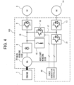
- FIG. 4 depicts a configuration of a drive system according, to the present embodiment.
- the drive system 100 includes a two-winding induction generator (IG: Induced Generator) 20, a traction inverter 9, an auxiliary machine inverter 12, a rectifier 8, an auxiliary converter 21, a discharging resistor 15, a DC-DC converter 10, and a power generation controller 30 that controls, the auxiliary converter 21 and the auxiliary converter 21.
- IG Induced Generator
- the rectifier 8 is connected, at the AC .side thereof, to the main winding of the two-winding induction generator 20 and connected, at the DC side thereof, to the traction inverter 9 and the discharging resistor 15 through the main side DC bus 16.
- the rectifier 8 rectifies AC power generated in the main winding into DC power and supplies the DC power to the main side DC bus 16.
- the discharging resistor 15 is connected to the main side DC bus 16.
- the discharging resistor 15 is energized upon regeneration action (upon retarding) of the traction motor 3 and consumes electric power (regenerative power) generated by a regeneration action of the traction motor 3.
- the auxiliary converter 21 is connected, at the AC side thereof, to the auxiliary winding of the two-winding induction generator 20 and connected, at the DC side thereof, to the auxiliary machine inverter 12.through the auxiliary side DC bus 17.
- the auxiliary converter 21 converts AC power generated in the auxiliary winding into DC power and supplies the DC power to the auxiliary side DC bus 17.
- the output voltage of the main winding of the two-winding induction generator 20 need not be a fixed voltage. Further, the voltages of the main winding and the auxiliary winding of the two-winding induction generator 20 vary substantially in proportion to each other. Therefore, by changing the voltage of the auxiliary winding of the two-winding induction generator 20 by the auxiliary converter 21, the output voltage of the main winding can be changed. Since the main winding can be excited from the auxiliary winding of the two-winding induction generator 20 by the auxiliary converter 21, the generator including the main side and the auxiliary side can be configured in a brushless configuration.
- the capacity of the traction inverter 9 is greater than the capacity of the auxiliary machine inverter 12, it is advantageous in terms of the cost that a converter that is more expensive than a rectifier is connected not to the traction inverter 9 but to the auxiliary machine inverter 12 whose demanded electric power is low.
- the auxiliary machine inverter 12 is controlled with a fixed voltage, the auxiliary winding of the two-winding induction generator 20 is controlled with a variable voltage.
- the auxiliary converter 21 can step up the voltage of the auxiliary winding of the two-winding induction generator 20, by designing the two-winding induction generator 20 such that the voltage of the auxiliary winding of the two-winding induction generator 20 becomes lower than the voltage demanded by the auxiliary machine inverter 12, the two-winding induction generator 20 can operate with the voltage demanded by the auxiliary machine inverter 12.
- FIG. 5 a relation between an action of the dump truck and an action of the two-winding induction generator 20 is depicted in FIG. 5 .
- the axis of abscissa indicates the engine speed and the axis of ordinate indicates the voltages of the main side DC bus 16 and the auxiliary side DC bus 17.
- the auxiliary side DC bus voltage in this instance is fixed at Vmin from the engine speed (Nmin) upon idling to the maximum speed (Nmax) of the engine.
- the main side DC bus voltage is the lowest voltage (> Vmin) upon idling and increases as the engine speed increases.
- the main side DC bus voltage Upon retarding (electric braking) of the vehicle, the main side DC bus voltage operates in the proximity of the maximum voltage Vmax.
- the main side DC bus voltage varies within this voltage range.
- the power generation controller 30 controls the field current of the two-winding induction generator 20 via the auxiliary converter 21 such that, in such an action of the vehicle and a voltage range as just described, the main side output power (load) and the auxiliary side output power (load) of the two-winding induction generator 20 are balanced.
- a vehicle that has an electric drive system such as a dump truck has actions that do not consume the load on the main side, namely, actions such as idling and retarding (electric braking). Since the main side output power is zero in the two actions, when the auxiliary side outputs electric power at this time, the voltage on the main side increases significantly. As a countermeasure for this case, it is conceivable, for example, to cause also the main side to generate electric power and cause the discharging resistor 15 depicted in FIG. 4 to consume the electric power thereby to establish output power balance between the main side and the auxiliary side.
- the DC-DC converter 10 depicted in FIG. 4 is used such that it acts to supply electric power generated by the main side to the auxiliary machine inverter 12. Since the DC-DC converter 10 acts in this manner, electric power generated by the main side upon idling or upon retarding can be supplied to the auxiliary machine. Therefore, the generated electric power is not consumed as loss by the discharging resistor 15 anymore and also it is possible to suppress deterioration of the fuel cost.
- the DC-DC converter 10 is a converter of the step-down type, and therefore, by decreasing the main side DC bus voltage, which varies within a voltage range higher than that of the auxiliary side DC bus 17 in response to a vehicle action, to the auxiliary side DC bus voltage, electric power can be supplied from the main side DC bus 16 to the auxiliary machine inverter 12.
- FIG. 6 is a functional block diagram of the power generation controller 30.
- the power generation controller 30 includes a vehicle action decision section 31, a converter output power determination section 32, an auxiliary converter controlling section 33, and a DC-DC converter controlling section 34.
- the power generation controller 30 is configured from a controller having a computation processing function and implements functions of the sections by executing a program stored in a storage device such as a ROM.
- the vehicle action decision section 31 decides which one of normal traveling, idling, and retarding the vehicle action is on the basis of an accelerator signal, a brake signal, a vehicle speed, and an engine speed, and outputs a result of the decision (vehicle action decision result) to the converter output power determination section 32.
- the accelerator signal, brake signal, vehicle speed, and engine speed are inputted, for example, from the control system of the dump truck or various sensors to the power generation controller 30.
- the converter output power determination section 32 determines an output power of the auxiliary converter 21 and an output power of the DC-DC converter 10 on the basis of a vehicle action decision result inputted from the vehicle action decision section 31 and an auxiliary machine demanded electric power signal (signal indicative of demanded electric power of the auxiliary machine inverter 12) inputted, for example, from the control system of the dump truck.
- the output power of the auxiliary converter 21 and the output power of the DC-DC converter 10 are determined such that the sum of the output power of the auxiliary converter 21 and the output power of the DC-DC converter 10 becomes equal to the auxiliary machine demanded electric power.
- the converter output power determination section 32 outputs a command for the instruction of the output electric power of the auxiliary converter 2.1 (auxiliary converter output power command) to the auxiliary converter controlling section 33, and outputs a command for the instruction of the output electric power of the DC-DC converter 10 (DC-DC converter output power command) to the DC-DC converter controlling section 34.
- the auxiliary converter controlling section 33 determines an output voltage of the auxiliary converter 21 in accordance with the auxiliary converter output power command and outputs a command signal (auxiliary converter voltage command signal) for the instruction of the output voltage to the DC-DC converter 10.
- the DC-DC converter controlling section 34 determines the output voltage of the DC-DC converter 10 in accordance with the DC-DC converter output power command and outputs a command signal (DC-DC converter voltage command) for the instruction of the output voltage to the DC-DC converter 10.
- FIG. 7 is a functional block diagram of the auxiliary converter controlling section 33.
- the auxiliary converter controlling section 33 includes a voltage controlling section 33a, a current limiting section 33b, and a current controlling section 33c.
- the auxiliary converter controlling section 33 performs feedback control of the auxiliary side DC bus voltage such that electric power corresponding to an auxiliary converter output power command is outputted from the auxiliary converter 21 to the auxiliary side DC bus 17.
- the voltage controlling section 33a determines output current of the auxiliary converter 21 (auxiliary converter current command) such that the difference between an auxiliary side DC bus voltage command from the converter output power determination section 32 and an auxiliary side DC bus voltage determined in advance is minimized, and outputs the determined output current to the current limiting section 33b.
- the current limiting section 33b limits the auxiliary converter current command in accordance with the auxiliary converter output power command and outputs the limited auxiliary converter current command to the current controlling section 33c.
- the current controlling section 33c determines an output voltage of the auxiliary converter 21 such that the difference between the auxiliary converter current command and the auxiliary converter current is minimized, and outputs a command signal for the instruction of the output voltage (auxiliary converter voltage command signal) to the auxiliary converter 21. Consequently, electric power corresponding to the auxiliary converter output power command is supplied from the auxiliary converter 21 to the auxiliary side DC bus 17.
- FIG. 8 is a functional block diagram of the DC-DC converter controlling section 34.
- the DC-DC converter controlling section 34 includes a current command computation section 34a and a current controlling section 34b.
- the DC-DC converter controlling section 34 performs feedback control of the DC-DC converter current such that electric power corresponding to the DC-DC converter output.power command is outputted from the DC-DC converter 10 to the auxiliary side DC bus 17.
- the current command computation section 34a determines output current of the DC-DC converter 10 (DC-DC converter current command) such that electric power corresponding to the DC-DC converter output power command is outputted from the DC-DC converter 10, and outputs the determined output current to the current controlling section 34b.
- the current controlling section 34b determines an output voltage of the DC-DC converter 10 such that the difference between the DC-DC converter current command and a DC-DC converter current determined in advance is minimized, and outputs a command signal according to the output voltage (DC-DC converter voltage command signal) to the DC-DC converter 10. Consequently, electric power corresponding to the DC-DC converter output power command is supplied from the DC-DC converter 10 to the auxiliary side DC bus 17.
- FIG. 9 is a flow chart depicting processing contents of the power generation controller 30. In the following, individual steps are described in order.
- the converter output power determination section 32 of the power generation controller 30 decides, on the basis of an accelerator signal, a brake signal, a vehicle speed, and an engine speed, which one of normal traveling, idling, and retarding the vehicle action is (step S100). For example, where conditions that the accelerator is OFF, that the brake is OFF, that the vehicle speed is lower than a threshold value that is set a little higher than zero, and that the engine speed is within a predetermined range lower than that upon normal traveling are satisfied, the converter output power determination section 32 decides that the vehicle action is idling.
- the converter output power determination section 32 decides that the vehicle action is retarding.
- the converter output power determination section 32 decides that the vehicle action is normal traveling.
- step S101 the converter output power determination section 32 and the auxiliary converter controlling section 33 carry out voltage control of the auxiliary side DC bus 17 (step S101). Consequently, the two-winding induction generator 20 generates electric power demanded by the auxiliary machine inverter 12 by the auxiliary winding thereof and drives the auxiliary machine motor 13.
- step S102 the power generation amount correction of the main winding can be carried out, for example, by distributing the power generation amount from the main winding to the auxiliary machine inverter 12 through the DC-DC converter 10.
- the converter output power determination section 32 determines an output power of the auxiliary converter 21 and an output power of the DC-DC converter 10 (step S103).
- the converter output power determination section 32 receives, as an input thereto, an auxiliary machine demanded electric power determined separately from the state of the vehicle at the time, determines output power commands for the auxiliary converter 21 and the DC-DC converter 10, and controls the output power of them on the basis of the output power commands.
- an action signal of the vehicle and an auxiliary machine demanded electric power may be inputted thereto to determine output power commands for the converters by table search or determine such output power commands by computation on the basis of a characteristic formula of the generator.
- an output power command of each converter although it is possible to change the magnitude of it freely, for example, if the converters individually share one half of the auxiliary machine demanded electric power, then the capacities of them can be minimized and besides made same as each other.
- step S103 the auxiliary converter controlling section 33 controls the output power of the auxiliary converter 21 and the DC-DC converter controlling section 34 controls the output power of the DC-DC converter 10 (step S104).
- step S104 the processes in and after S100 are repeated.
- FIG. 10 depicts a flow of electric power of the drive system 100 in a case where it is decided that the vehicle action is normal traveling.
- electric power generated in the main winding of the two-winding induction generator 20 is supplied to the main side DC bus 16 via the rectifier 8.
- the electric power supplied to the main side DC bus 16 is supplied to the traction motor 3 via the traction inverter 9.
- Electric power generated in the auxiliary winding of the two-winding induction generator 20 is supplied to the auxiliary side DC bus 17 via the auxiliary converter 21.
- the electric power supplied to the auxiliary side DC bus 17 is supplied to the auxiliary machine motor 13 via the auxiliary machine inverter 12.
- FIG. 11 depicts a flow of electric power of the drive system 100 when it is decided that the vehicle action is idling.
- electric power generated in the main winding of the two-winding induction generator 20 is supplied to the main side DC bus 16 via the rectifier 8.
- the electric power supplied to the main side DC bus 16 is supplied to the auxiliary side DC bus 17 via the DC-DC converter 10.
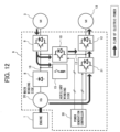
- FIG. 12 depicts a flow of electric power of the drive system 100 in a case where it is decided that the vehicle action is retarding.
- the rectifier 8 and the main winding of the two-winding induction generator 20 are placed into a non-conducting state.
- Part of the regenerative power supplied to the main side DC bus 16 is supplied to the auxiliary side DC bus 17 via the DC-DC converter 10.
- the remaining part of the regeneration action supplied to the main side DC bus 16 is consumed by the discharging resistor 15.
- the drive system 100 for a dump truck includes a two-winding induction generator 20 having a primary winding including a main winding and an auxiliary winding, a rectifier 8 that rectifies AC power generated in the main winding into DC power, an auxiliary converter 21 that converts AC power generated in the auxiliary winding into DC power, a traction inverter 9 that is connected to the rectifier 8 via a main side DC bus 16, converts the DCpower supplied from the rectifier 8 into AC power, and supplies the AC power to a traction motor 3, an auxiliary machine inverter 12 that is connected to the auxiliary converter 21 via an auxiliary side DC bus 17, converts the DC power supplied from the auxiliary converter 21 into AC power, and supplies the AC power to an auxiliary machine motor 13, and a controller 30 that controls the auxiliary converter 21, in which the drive system 100 includes a DC-DC converter 10 connected to the main side DC bus 16 and the auxiliary side DC bus 17, and the controller 30 controls the DC-DC converter 10 such that electric power of the main side DC bus 16 is supplied
- the controller 30 decides, on the basis of control signals of the dump truck (accelerator signal, brake signal, vehicle speed, and engine speed), which one of normal traveling, idling, and retarding the action of the dump truck is, and controls, when it is decided that the action of the dump truck is idling or retarding, the DC-DC converter 10 such that electric power of the main side DC bus 16 is supplied to the auxiliary side DC bus 17 via the DC-DC converter 10. Consequently, when there is no load on the main winding side (no load on the traction motor 3) (upon idling or upon retarding), it is possible to supply electric power generated in the main winding or regenerative power of the traction motor 3 to the auxiliary machine inverter 12.
- the controller 30, when electric power is to be supplied from the main side DC bus 16 to the auxiliary side DC bus 17 via the DC-DC converter 10, controls the auxiliary converter 21 and the DC-DC converter 10 such that the sum of electric power to be supplied to the auxiliary side DC bus 17 via the auxiliary converter 21 and electric power to be supplied to the auxiliary side DC bus 17 via the DC-DC converter 10 becomes equal to demanded electric power of the auxiliary machine inverter 12. Consequently, it becomes possible to supply just enough auxiliary machine demanded electric power from the auxiliary converter 21 and the DC-DC converter 10 to the auxiliary machine inverter 12.
Landscapes
- Engineering & Computer Science (AREA)
- Power Engineering (AREA)
- Transportation (AREA)
- Mechanical Engineering (AREA)
- Chemical & Material Sciences (AREA)
- Combustion & Propulsion (AREA)
- Automation & Control Theory (AREA)
- Electric Propulsion And Braking For Vehicles (AREA)
- Dc-Dc Converters (AREA)
- Hybrid Electric Vehicles (AREA)
- Control Of Eletrric Generators (AREA)
Abstract
Description
- The present invention relates to a drive system that includes a two-winding induction generator having a primary winding including a main winding and an auxiliary winding.
- In a mine, in order to transport ores or stripped soil from a loading place to an unloading place, a large number of dump trucks having a load capacity of 100 tons or more are operating. A route from the loading place to the unloading place is determined fixedly, and a dump truck repeatedly travels back and forth along the same route. Along one route, a plurality of dumps of the same vehicle rank travel, and the operating time of them is 24 hours. In regard to a plurality of dump trucks that are large in size and operate for a long period of time, the transportation efficiency indicated by a work load per unit cost (initial cost + running cost) is emphasized. Therefore, for dump trucks, in order to aim for improvement of this barometer, various measures are taken such that the initial cost is suppressed as far as possible and the running cost is reduced. In order to reduce the running cost, a drive system that is high in efficiency and requires a less maintenance cost is needed in order to reduce the fuel consumption. An electric drive system is available as one of such drive systems that are high in efficiency and can suppress the cost required for the maintenance. While a mechanical drive system transmits power of an engine to tires using a torque converter and a speed change gear, the electric drive system drives a generator by an engine and uses electric power generated by the generator to drive a traction motor linked to a tire shaft. As such an electric drive system for a dump truck as just described, for example, a technology disclosed in
Patent Document 1 is available. According to this technology, the electric drive system for a dump truck includes a main generator that supplies electric power to a traction motor, an auxiliary generator that supplies electric power to an auxiliary machine device, and a DC-DC converter that receives regenerative power from the traction motor, which is generated upon retarding (electric braking) of the vehicle, as an input thereto and supplies electric power to the auxiliary machine device, and the electric drive system can thereby reduce the energy consumption of the auxiliary generator. - Further, in regard to a hybrid vehicle to which an electric drive system is applied, for example, a technology disclosed in another patent document is available. According to this technology, the electric drive system includes a converter that converts a high voltage power supply to a low voltage and includes an auxiliary battery that supplies electric power to various electrical equipment. For the backup of the auxiliary power supply circuit, an alternator is linked to an engine separately such that, even in a case where the auxiliary power supply fails, operation of the various electrical equipment can be performed.
-
- Patent Document 1:
PCT Patent Publication No. WO2018/047270 - Patent Document 2:
JP-2000-224709-A - In
Patent Document 1, the main generator and the auxiliary generator are configured from field winding generators separate from each other, and also some slip rings for supplying field current to a rotor are needed for each of the field winding of the generators. This makes the physique of the overall generators large and also increases the cost. Further, the DC-DC converter that supplies electric power to the auxiliary machine equipment supplies regenerative power from the traction motor upon retarding (electric braking) of the vehicle, and nothing is mentioned about scaling down of the converter for power generation that operates upon normal traveling of the vehicle. - Meanwhile,
Patent Document 2 describes nothing of means for supplying electric power to the various electric equipment simultaneously from the auxiliary power supply and the alternator, and each of the power supplies can solely supply electric power to the electric equipment. Patent Document.2 thus mentions nothing about scaling down of the various power supplies. - Therefore, it is conceivable to use, as means for solving the problems described above, a two-winding induction generator in which a winding of a main generator and a winding of an auxiliary generator are formed as an integrated generator (of the two-winding type) and no slip ring is needed. However, this two-winding induction generator seems to have problems in that it needs a converter for control and that, in order to satisfy power generation of the main winding side and power generation of the auxiliary winding side at the same time, the converter is increased in size.
- The present invention has been made in view of the problems described above, and the object of the present invention resides in provision of a drive system for a dump truck capable of suppressing increase in size of a converter that controls a two-winding induction generator.
- In order to achieve the object described above, according to the present invention, there is provided a drive system for a dump truck, the drive system including a two-winding induction generator having a primary winding including a main winding and an auxiliary winding, a rectifier,that rectifies AC power generated in the main winding into DC power, an auxiliary converter that converts AC power generated in the auxiliary winding into DC power, a traction inverter that is connected to the rectifier through a main side DC bus, converts the DC power supplied from the rectifier into AC power, and supplies the AC power to a traction motor of the dump truck, an auxiliary machine inverter that is connected to the auxiliary converter through an auxiliary side DC bus, converts the DC power supplied from the auxiliary converter into AC power, and supplies the AC power to an auxiliary machine motor of the dump truck, and a controller that controls the auxiliary converter, in which the drive system further includes a DC-DC converter connected to the main side DC bus and the auxiliary side DC bus, and the controller controls the DC-DC converter such that electric power of the main side DC bus is supplied to the auxiliary side DC bus via the DC-DC converter.
- With the present invention configured in such a manner as described above, since electric power can be supplied from both of the auxiliary converter and the DC-DC converter to the auxiliary machine inverter, increase in reactive electric current flow to the auxiliary converter (drop of the power factor on the auxiliary winding side) can be suppressed. Consequently, it is possible to scale down the auxiliary converter while the efficiency of the drive system is maintained.
- With the present invention, in the drive system for a dump truck that includes a two-winding induction generator, it becomes possible to suppress increase in size of the converters that control the two-winding induction generator.
-
-
FIG. 1 is a schematic diagram of a dump truck for mining in which a drive system according to an embodiment of the present invention is incorporated. -
FIG. 2 is a block diagram of a drive system according to a prior art. -
FIG. 3 is a block diagram depicting a modification of the drive system according to the prior art. -
FIG. 4 is a block diagram of the drive system according to the embodiment of the present invention. -
FIG. 5 is a view depicting a relation between an action of a dump truck and an action of a two-winding induction generator. -
FIG. 6 is a functional block diagram of a power generation controller. , -
FIG. 7 is a functional block diagram of an auxiliary converter controlling section. -
FIG. 8 is a functional block diagram of a DC-DC converter controlling section. -
FIG. 9 is a flow chart depicting processing contents of the power generation controller. -
FIG. 10 is a view depicting a flow of electric power of the drive system in a case where it is decided that the vehicle action is normal traveling. -
FIG. 11 is a view depicting a flow of electric power of the drive system in a case where it is decided that the vehicle action is idling. -
FIG. 12 is a view depicting a flow of electric power of the drive system in a case where it is decided that the vehicle action is retarding. - In the following, an embodiment of the present invention is described with reference to the drawings. It is to be noted that, in the figures, like elements are denoted by like reference characters and overlapping description of them is omitted suitably.
- First, a dump truck for mining in which a drive system according to the embodiment of the present invention is incorporated is described. The dump truck for mining repeatedly performs a series of work cycles of loading sediment at a loading place, traveling from the loading place to an unloading place, discharging the sediment at the unloading place, and traveling from the unloading place to the loading place.
-
FIG. 1 depicts a configuration of a dump truck for mining. Referring toFIG. 1 , the dump truck for mining includes acarrier 7 attached pivotably in an upward and downward direction at an upper side rear portion of a vehicle body, and a.driving seat 6 provided at an upper side front portion of the vehicle body. Further, a pair of left and right drivenwheels right driving wheels driving wheels traction motor 3. - Now, a drive system of the electrically driven type that drives the
driving wheels -
FIG. 2 depicts a configuration of a drive system according to a prior art. Referring toFIG. 2 , thedrive system 100X includes a main generator (MG: Main Generator) 2 and an auxiliary generator.(SG: Sub Generator) 14 that are driven by anengine 1, atraction motor 3 that drives thedriving wheels auxiliary machine motor 13, atraction inverter 9, anauxiliary machine inverter 12, arectifier 8, anauxiliary rectifier 11, adischarging resistor 15, and apower generation controller 30X that controls themain generator 2 and theauxiliary generator 14. - The
main generator 2 and theauxiliary generator 14 convert rotational energy of theengine 1 into electric energy (AC power). Therectifier 8 rectifies AC power supplied from themain generator 2 into DC power and supplies the DC power to thetraction inverter 9. Thetraction inverter 9 converts the DC power supplied from therectifier 8 into AC power and supplies the AC power to thetraction motor 3. - The
auxiliary generator 14 is utilized as a power supply for an auxiliary machine system that drives an auxiliary machine such as cooling equipment. Theauxiliary rectifier 11 rectifies AC power supplied from theauxiliary generator 14 into DC power and supplies the DC power to theauxiliary machine inverter 12. Theauxiliary machine inverter 12 converts the DC power supplied from theauxiliary rectifier 11 into AC power and supplies the AC power to theauxiliary machine motor 13. Theauxiliary machine motor 13 drives cooling equipment (not depicted) such as a blower. It is to be noted that, although only one set of theauxiliary machine inverter 12 and theauxiliary machine motor 13 is depicted as the auxiliary machine system inFIG. 2 , since an actual vehicle includes a plurality of equipment that correspond to auxiliary machines, a plurality of auxiliary machine inverters and a plurality of auxiliary machine motors having capacities different from each other are incorporated. - Here, a configuration is examined which includes a DC-
DC converter 10 that connects a mainside DC bus 16 and an auxiliaryside DC bus 17 to each other in order to make it possible to supply electric power of the mainside DC bus 16 to the auxiliaryside DC bus 17 in thedrive system 100X depicted inFIG. 2 . - Referring to.
FIG. 3 , apower generation controller 30Y can drive theauxiliary machine motor 13 by stepping down regenerative power from thetraction motor 3, which is generated upon retarding (electric braking) of the vehicle, by the DC-DC converter 10 and supplying the stepped down regenerative power to theauxiliary machine inverter 12.. By using regenerative power of thetraction motor 3 upon retarding of the vehicle to drive the auxiliary machine, it becomes possible to reduce the power of theengine 1, which is consumed for driving of the auxiliary machine upon braking of the vehicle. This can contribute to reduction of the fuel consumption of theengine 1, It is to be noted that the regenerative electric power from thetraction motor 3 is usually higher than power needed by the auxiliary machine and cannot be absorbed only by the DC-DC converter 10. Therefore, by consuming surplus regenerative power by the dischargingresistor 15, electric braking force can be obtained without shortage from thetraction motor 3. - The
drive system 100Y described above basically is a drive system of the diesel electric type and drives the tires through a torque converter or a transmission without directly driving the tires, using rotation force of the engine as in a mechanically driven dump, and rotational driving of the engine is utilized for electric power generation of a generator. Thedrive system 100Y includes amain generator 2 that generates electric power to be used for traveling and anauxiliary generator 14 that generates electric power to be used for auxiliary machine driving. Although the types of the generators are not specifically restricted, for example, if they are formed as field winding generators in which a field winding is provided on the rotor, then a converter that is needed when generated electric power is converted into direct current as depicted inFIG. 3 can be formed from an inexpensive rectifier. However, where the field winding type generator described above is used, themain generator 2 and theauxiliary generator 14 are configured from separate generators and need a slip ring for supplying field current to the rotor, resulting in increase in size of the physique of the overall generator and also in cost. - Therefore, as means for solving the problems, it is conceivable to use, in place of the
main generator 2 and theauxiliary generator 14, a two-winding induction generator in which the winding of themain generator 2 and the winding of theauxiliary generator 14 are formed as an integrated generator (of the two-winding type) and besides do not need a slip ring is applied. -
FIG. 4 depicts a configuration of a drive system according, to the present embodiment. Referring toFIG. 4 , thedrive system 100 includes a two-winding induction generator (IG: Induced Generator) 20, atraction inverter 9, anauxiliary machine inverter 12, arectifier 8, anauxiliary converter 21, a dischargingresistor 15, a DC-DC converter 10, and apower generation controller 30 that controls, theauxiliary converter 21 and theauxiliary converter 21. - The
rectifier 8 is connected, at the AC .side thereof, to the main winding of the two-windinginduction generator 20 and connected, at the DC side thereof, to thetraction inverter 9 and the dischargingresistor 15 through the mainside DC bus 16. Therectifier 8 rectifies AC power generated in the main winding into DC power and supplies the DC power to the mainside DC bus 16. The dischargingresistor 15 is connected to the mainside DC bus 16. The dischargingresistor 15 is energized upon regeneration action (upon retarding) of thetraction motor 3 and consumes electric power (regenerative power) generated by a regeneration action of thetraction motor 3. Theauxiliary converter 21 is connected, at the AC side thereof, to the auxiliary winding of the two-windinginduction generator 20 and connected, at the DC side thereof, to the auxiliary machine inverter 12.through the auxiliaryside DC bus 17. Theauxiliary converter 21 converts AC power generated in the auxiliary winding into DC power and supplies the DC power to the auxiliaryside DC bus 17. - Here, since the main winding of the two-winding
induction generator 20 is connected to thetraction inverter 9 only by therectifier 8 without connection of a battery or a capacity of a large capacity or is not connected to an electric power system, the output voltage of the main winding of the two-windinginduction generator 20 need not be a fixed voltage. Further, the voltages of the main winding and the auxiliary winding of the two-windinginduction generator 20 vary substantially in proportion to each other. Therefore, by changing the voltage of the auxiliary winding of the two-windinginduction generator 20 by theauxiliary converter 21, the output voltage of the main winding can be changed. Since the main winding can be excited from the auxiliary winding of the two-windinginduction generator 20 by theauxiliary converter 21, the generator including the main side and the auxiliary side can be configured in a brushless configuration. - In the
drive system 100 according to the present embodiment, since the capacity of thetraction inverter 9 is greater than the capacity of theauxiliary machine inverter 12, it is advantageous in terms of the cost that a converter that is more expensive than a rectifier is connected not to thetraction inverter 9 but to theauxiliary machine inverter 12 whose demanded electric power is low. Further, although theauxiliary machine inverter 12 is controlled with a fixed voltage, the auxiliary winding of the two-windinginduction generator 20 is controlled with a variable voltage. Since theauxiliary converter 21 can step up the voltage of the auxiliary winding of the two-windinginduction generator 20, by designing the two-windinginduction generator 20 such that the voltage of the auxiliary winding of the two-windinginduction generator 20 becomes lower than the voltage demanded by theauxiliary machine inverter 12, the two-windinginduction generator 20 can operate with the voltage demanded by theauxiliary machine inverter 12. - Here, a relation between an action of the dump truck and an action of the two-winding
induction generator 20 is depicted inFIG. 5 . The axis of abscissa indicates the engine speed and the axis of ordinate indicates the voltages of the mainside DC bus 16 and the auxiliaryside DC bus 17. The auxiliary side DC bus voltage in this instance is fixed at Vmin from the engine speed (Nmin) upon idling to the maximum speed (Nmax) of the engine. In contrast, the main side DC bus voltage is the lowest voltage (> Vmin) upon idling and increases as the engine speed increases. Upon retarding (electric braking) of the vehicle, the main side DC bus voltage operates in the proximity of the maximum voltage Vmax. On the other hand, upon normal traveling of the vehicle, the main side DC bus voltage varies within this voltage range. Thepower generation controller 30 controls the field current of the two-windinginduction generator 20 via theauxiliary converter 21 such that, in such an action of the vehicle and a voltage range as just described, the main side output power (load) and the auxiliary side output power (load) of the two-windinginduction generator 20 are balanced. - On the other hand, a vehicle that has an electric drive system such as a dump truck has actions that do not consume the load on the main side, namely, actions such as idling and retarding (electric braking). Since the main side output power is zero in the two actions, when the auxiliary side outputs electric power at this time, the voltage on the main side increases significantly. As a countermeasure for this case, it is conceivable, for example, to cause also the main side to generate electric power and cause the discharging
resistor 15 depicted inFIG. 4 to consume the electric power thereby to establish output power balance between the main side and the auxiliary side. However, with this technique, the electric power generated by the main side is merely consumed by the dischargingresistor 15 and therefore becomes mere loss, and as a result, the fuel cost of the vehicle is deteriorated. Further, upon idling, since the engine speed is low, also it is supposed that the discharge starting voltage of the dischargingresistor 15 is not reached. - In order to cope with the subject described above, in the present embodiment, the DC-
DC converter 10 depicted inFIG. 4 is used such that it acts to supply electric power generated by the main side to theauxiliary machine inverter 12. Since the DC-DC converter 10 acts in this manner, electric power generated by the main side upon idling or upon retarding can be supplied to the auxiliary machine. Therefore, the generated electric power is not consumed as loss by the dischargingresistor 15 anymore and also it is possible to suppress deterioration of the fuel cost. Further, the DC-DC converter 10 is a converter of the step-down type, and therefore, by decreasing the main side DC bus voltage, which varies within a voltage range higher than that of the auxiliaryside DC bus 17 in response to a vehicle action, to the auxiliary side DC bus voltage, electric power can be supplied from the mainside DC bus 16 to theauxiliary machine inverter 12. -
FIG. 6 is a functional block diagram of thepower generation controller 30. Referring toFIG. 6 , thepower generation controller 30 includes a vehicleaction decision section 31, a converter outputpower determination section 32, an auxiliaryconverter controlling section 33, and a DC-DCconverter controlling section 34. Thepower generation controller 30 is configured from a controller having a computation processing function and implements functions of the sections by executing a program stored in a storage device such as a ROM. - The vehicle
action decision section 31 decides which one of normal traveling, idling, and retarding the vehicle action is on the basis of an accelerator signal, a brake signal, a vehicle speed, and an engine speed, and outputs a result of the decision (vehicle action decision result) to the converter outputpower determination section 32. Here, the accelerator signal, brake signal, vehicle speed, and engine speed are inputted, for example, from the control system of the dump truck or various sensors to thepower generation controller 30. - The converter output
power determination section 32 determines an output power of theauxiliary converter 21 and an output power of the DC-DC converter 10 on the basis of a vehicle action decision result inputted from the vehicleaction decision section 31 and an auxiliary machine demanded electric power signal (signal indicative of demanded electric power of the auxiliary machine inverter 12) inputted, for example, from the control system of the dump truck. Here, the output power of theauxiliary converter 21 and the output power of the DC-DC converter 10 are determined such that the sum of the output power of theauxiliary converter 21 and the output power of the DC-DC converter 10 becomes equal to the auxiliary machine demanded electric power. Further, the distribution of the output power of theauxiliary converter 21 and the output power of the DC-DC converter 10 from the auxiliary machine demanded electric power is adjusted in response to the vehicle action. The converter outputpower determination section 32 outputs a command for the instruction of the output electric power of the auxiliary converter 2.1 (auxiliary converter output power command) to the auxiliaryconverter controlling section 33, and outputs a command for the instruction of the output electric power of the DC-DC converter 10 (DC-DC converter output power command) to the DC-DCconverter controlling section 34. - The auxiliary
converter controlling section 33 determines an output voltage of theauxiliary converter 21 in accordance with the auxiliary converter output power command and outputs a command signal (auxiliary converter voltage command signal) for the instruction of the output voltage to the DC-DC converter 10. The DC-DCconverter controlling section 34 determines the output voltage of the DC-DC converter 10 in accordance with the DC-DC converter output power command and outputs a command signal (DC-DC converter voltage command) for the instruction of the output voltage to the DC-DC converter 10. -
FIG. 7 is a functional block diagram of the auxiliaryconverter controlling section 33. Referring toFIG. 7 , the auxiliaryconverter controlling section 33 includes avoltage controlling section 33a, a current limitingsection 33b, and acurrent controlling section 33c. The auxiliaryconverter controlling section 33 performs feedback control of the auxiliary side DC bus voltage such that electric power corresponding to an auxiliary converter output power command is outputted from theauxiliary converter 21 to the auxiliaryside DC bus 17. - The
voltage controlling section 33a determines output current of the auxiliary converter 21 (auxiliary converter current command) such that the difference between an auxiliary side DC bus voltage command from the converter outputpower determination section 32 and an auxiliary side DC bus voltage determined in advance is minimized, and outputs the determined output current to the current limitingsection 33b. The current limitingsection 33b limits the auxiliary converter current command in accordance with the auxiliary converter output power command and outputs the limited auxiliary converter current command to thecurrent controlling section 33c. Thecurrent controlling section 33c determines an output voltage of theauxiliary converter 21 such that the difference between the auxiliary converter current command and the auxiliary converter current is minimized, and outputs a command signal for the instruction of the output voltage (auxiliary converter voltage command signal) to theauxiliary converter 21. Consequently, electric power corresponding to the auxiliary converter output power command is supplied from theauxiliary converter 21 to the auxiliaryside DC bus 17. -
FIG. 8 is a functional block diagram of the DC-DCconverter controlling section 34. Referring toFIG. 8 , the DC-DCconverter controlling section 34 includes a currentcommand computation section 34a and acurrent controlling section 34b. The DC-DCconverter controlling section 34 performs feedback control of the DC-DC converter current such that electric power corresponding to the DC-DC converter output.power command is outputted from the DC-DC converter 10 to the auxiliaryside DC bus 17. - The current
command computation section 34a determines output current of the DC-DC converter 10 (DC-DC converter current command) such that electric power corresponding to the DC-DC converter output power command is outputted from the DC-DC converter 10, and outputs the determined output current to thecurrent controlling section 34b. Thecurrent controlling section 34b determines an output voltage of the DC-DC converter 10 such that the difference between the DC-DC converter current command and a DC-DC converter current determined in advance is minimized, and outputs a command signal according to the output voltage (DC-DC converter voltage command signal) to the DC-DC converter 10. Consequently, electric power corresponding to the DC-DC converter output power command is supplied from the DC-DC converter 10 to the auxiliaryside DC bus 17. -
FIG. 9 is a flow chart depicting processing contents of thepower generation controller 30. In the following, individual steps are described in order. - First, the converter output
power determination section 32 of thepower generation controller 30 decides, on the basis of an accelerator signal, a brake signal, a vehicle speed, and an engine speed, which one of normal traveling, idling, and retarding the vehicle action is (step S100). For example, where conditions that the accelerator is OFF, that the brake is OFF, that the vehicle speed is lower than a threshold value that is set a little higher than zero, and that the engine speed is within a predetermined range lower than that upon normal traveling are satisfied, the converter outputpower determination section 32 decides that the vehicle action is idling. Meanwhile, for example, where conditions that the brake is ON, that the vehicle speed is equal to or higher than the threshold value, and that the engine speed is equal to or higher than a predetermined value are satisfied, the converter outputpower determination section 32 decides that the vehicle action is retarding. On the other hand, where conditions that the brake is OFF, that the vehicle speed is equal to or higher than the threshold value, and that the engine speed is equal to or higher than the predetermined value are.satisfied, the converter outputpower determination section 32 decides that the vehicle action is normal traveling. - Where it is decided in step S100 that the vehicle action is normal traveling, the converter output
power determination section 32 and the auxiliaryconverter controlling section 33 carry out voltage control of the auxiliary side DC bus 17 (step S101). Consequently, the two-windinginduction generator 20 generates electric power demanded by theauxiliary machine inverter 12 by the auxiliary winding thereof and drives theauxiliary machine motor 13. Here, if the power generation amount of the auxiliary winding in the two-windinginduction generator 20 varies, then also the power generation amount and the voltage of the main winding vary. As a result, if an influence of the variation on the action of thetraction motor 3 occurs, then the power generation amount of the main winding is corrected (step S102). This power generation amount correction of the main winding can be carried out, for example, by distributing the power generation amount from the main winding to theauxiliary machine inverter 12 through the DC-DC converter 10. After step S102, processes in and after step S100 are performed repeatedly. - Where it is decided in step S100 that the vehicle action is retarding or idling, the converter output
power determination section 32 determines an output power of theauxiliary converter 21 and an output power of the DC-DC converter 10 (step S103). In particular, the converter outputpower determination section 32 receives, as an input thereto, an auxiliary machine demanded electric power determined separately from the state of the vehicle at the time, determines output power commands for theauxiliary converter 21 and the DC-DC converter 10, and controls the output power of them on the basis of the output power commands. It is to be noted that, in regard to the configuration of the converter outputpower determination section 32, an action signal of the vehicle and an auxiliary machine demanded electric power may be inputted thereto to determine output power commands for the converters by table search or determine such output power commands by computation on the basis of a characteristic formula of the generator. Further, as regards an output power command of each converter, although it is possible to change the magnitude of it freely, for example, if the converters individually share one half of the auxiliary machine demanded electric power, then the capacities of them can be minimized and besides made same as each other. - Subsequently to step S103, the auxiliary
converter controlling section 33 controls the output power of theauxiliary converter 21 and the DC-DCconverter controlling section 34 controls the output power of the DC-DC converter 10 (step S104). After step S104, the processes in and after S100 are repeated. -
FIG. 10 depicts a flow of electric power of thedrive system 100 in a case where it is decided that the vehicle action is normal traveling. Referring toFIG. 10 , electric power generated in the main winding of the two-windinginduction generator 20 is supplied to the mainside DC bus 16 via therectifier 8. The electric power supplied to the mainside DC bus 16 is supplied to thetraction motor 3 via thetraction inverter 9. Electric power generated in the auxiliary winding of the two-windinginduction generator 20 is supplied to the auxiliaryside DC bus 17 via theauxiliary converter 21. The electric power supplied to the auxiliaryside DC bus 17 is supplied to theauxiliary machine motor 13 via theauxiliary machine inverter 12. -
FIG. 11 depicts a flow of electric power of thedrive system 100 when it is decided that the vehicle action is idling. Referring toFIG. 11 , electric power generated in the main winding of the two-windinginduction generator 20 is supplied to the mainside DC bus 16 via therectifier 8. The electric power supplied to the mainside DC bus 16 is supplied to the auxiliaryside DC bus 17 via the DC-DC converter 10. Electric power generated in the auxiliary winding is supplied to the auxiliaryside DC bus 17 via theauxiliary converter 21. Consequently, the sum of the output electric power of theauxiliary converter 21 and the output electric power of the DC-DC converter 10 (= auxiliary machine demanded electric power) is supplied to theauxiliary machine inverter 12. -
FIG. 12 depicts a flow of electric power of thedrive system 100 in a case where it is decided that the vehicle action is retarding. Referring toFIG. 12 , if regenerative power of thetraction motor 3 is supplied to the mainside DC bus 16, then since the voltage of the mainside DC bus 16 is higher than the output voltage of therectifier 8, therectifier 8 and the main winding of the two-windinginduction generator 20 are placed into a non-conducting state. Part of the regenerative power supplied to the mainside DC bus 16 is supplied to the auxiliaryside DC bus 17 via the DC-DC converter 10. The remaining part of the regeneration action supplied to the mainside DC bus 16 is consumed by the dischargingresistor 15. Electric power generated in the auxiliary winding is supplied to the auxiliaryside DC bus 17 via theauxiliary converter 21. Consequently, the sum of the output electric power of theauxiliary converter 21 and the output electric power of the DC-DC converter 10 (= auxiliary machine demanded electric power) is supplied to theauxiliary machine inverter 12. - In the present embodiment, the
drive system 100 for a dump truck includes a two-windinginduction generator 20 having a primary winding including a main winding and an auxiliary winding, arectifier 8 that rectifies AC power generated in the main winding into DC power, anauxiliary converter 21 that converts AC power generated in the auxiliary winding into DC power, atraction inverter 9 that is connected to therectifier 8 via a mainside DC bus 16, converts the DCpower supplied from therectifier 8 into AC power, and supplies the AC power to atraction motor 3, anauxiliary machine inverter 12 that is connected to theauxiliary converter 21 via an auxiliaryside DC bus 17, converts the DC power supplied from theauxiliary converter 21 into AC power, and supplies the AC power to anauxiliary machine motor 13, and acontroller 30 that controls theauxiliary converter 21, in which thedrive system 100 includes a DC-DC converter 10 connected to the mainside DC bus 16 and the auxiliaryside DC bus 17, and thecontroller 30 controls the DC-DC converter 10 such that electric power of the mainside DC bus 16 is supplied to the auxiliaryside DC bus 17 via the DC-DC converter 10. - With the present embodiment configured in such a manner as described above, since electric power can be supplied from both of the
auxiliary converter 21 and the DC-DC converter 10 to theauxiliary machine inverter 12, increase in reactive electric current flow to the auxiliary converter 21 (drop of the power factor on the auxiliary winding side) can be suppressed. Consequently, it is possible to scale down the auxiliary converter while the efficiency of the drive system is maintained. - Further, the
controller 30 decides, on the basis of control signals of the dump truck (accelerator signal, brake signal, vehicle speed, and engine speed), which one of normal traveling, idling, and retarding the action of the dump truck is, and controls, when it is decided that the action of the dump truck is idling or retarding, the DC-DC converter 10 such that electric power of the mainside DC bus 16 is supplied to the auxiliaryside DC bus 17 via the DC-DC converter 10. Consequently, when there is no load on the main winding side (no load on the traction motor 3) (upon idling or upon retarding), it is possible to supply electric power generated in the main winding or regenerative power of thetraction motor 3 to theauxiliary machine inverter 12. - Further, the
controller 30, when electric power is to be supplied from the mainside DC bus 16 to the auxiliaryside DC bus 17 via the DC-DC converter 10, controls theauxiliary converter 21 and the DC-DC converter 10 such that the sum of electric power to be supplied to the auxiliaryside DC bus 17 via theauxiliary converter 21 and electric power to be supplied to the auxiliaryside DC bus 17 via the DC-DC converter 10 becomes equal to demanded electric power of theauxiliary machine inverter 12. Consequently, it becomes possible to supply just enough auxiliary machine demanded electric power from theauxiliary converter 21 and the DC-DC converter 10 to theauxiliary machine inverter 12. - Although the embodiment of the present invention has been described in detail, the present invention is not limited to the embodiment described above but includes various modifications. For example, the embodiment described above has been explained in detail in order to explain the present invention in a way easy to understand and is not necessarily restricted to those that include all. configurations described above.
-
- 1: Engine
- 2: Main generator
- 3: Traction motor
- 4: Driven wheel
- 5: Driving wheel
- 6: Driving seat
- 7: Carrier
- 8: Rectifier
- 9: Traction inverter
- 10: DC-DC converter
- 11: Auxiliary rectifier
- 12: Auxiliary machine inverter
- 13: Auxiliary machine motor
- 14: Auxiliary generator
- 15: Discharging resistor
- 16: Main side DC bus
- 17: Auxiliary side DC bus
- 20: Two-winding induction generator
- 21: Auxiliary converter
- 30, 30X, 30Y: Power generation controller (controller)
- 31: Vehicle action decision section
- 32: Converter output power determination section
- 33: Auxiliary converter controlling section
- 33a: Voltage controlling section
- 33b: Current limiting section
- 33c: Current controlling section
- 34: DC-DC converter controlling section
- 34a: Current command computation section
- 34b: Current controlling section
- 100, 100X, 100Y: Drive system
Claims (3)
- A drive system for a dump truck, the drive system comprising:a two-winding induction generator having a primary winding including a main winding and an auxiliary winding;a rectifier that rectifies alternating-current power generated in the main winding into direct-current power;an auxiliary converter that converts alternating-current power generated in the auxiliary winding into direct-current power;a traction inverter that is connected to the rectifier through a main side DC bus, converts the direct-current power supplied from the rectifier into alternating-current power, and supplies the alternating-current power to a traction motor of the dump truck;an auxiliary machine inverter that is connected to the auxiliary converter through an auxiliary side DC bus, converts the direct-current power supplied from the auxiliary converter into alternating-current power, and supplies the alternating-current power to an auxiliary machine motor of the dump truck; anda controller that controls the auxiliary converter, whereinthe drive system includes a DC-DC converter connected to the main side DC bus and the auxiliary side DC bus, andthe controller is configured to control the DC-DC converter such that electric power of the main side DC bus is supplied to the auxiliary side DC bus via the DC-DC converter.
- The drive system for a dump truck according to claim 1, wherein
the controller is configured to decide, on a basis of a control signal of the dump truck, which one of normal traveling, idling, and retarding an action of the dump truck is and control, in a case where it is decided that the action of the dump truck is.idling or retarding, the DC-DC converter such that electric power of the main side DC bus is supplied to the auxiliary side DC bus via the DC-DC converter. - The drive system for a dump truck according to claim 2, wherein,
the controller is configured to, in a case where electric power is to be supplied from the main side DC bus to the auxiliary side DC bus via the DC-DC converter, control the auxiliary converter and the DC-DC converter such that sum of electric power to be supplied to the auxiliary side DC bus via the auxiliary converter and electric power to be supplied to the auxiliary side DC bus via the DC-DC converter becomes equal to demanded electric power of the auxiliary machine inverter.
Applications Claiming Priority (2)
| Application Number | Priority Date | Filing Date | Title |
|---|---|---|---|
| JP2021053049A JP7053919B1 (en) | 2021-03-26 | 2021-03-26 | Dump truck drive system |
| PCT/JP2022/004956 WO2022201927A1 (en) | 2021-03-26 | 2022-02-08 | Drive system for dump truck |
Publications (2)
| Publication Number | Publication Date |
|---|---|
| EP4316891A1 true EP4316891A1 (en) | 2024-02-07 |
| EP4316891A4 EP4316891A4 (en) | 2025-01-15 |
Family
ID=81260047
Family Applications (1)
| Application Number | Title | Priority Date | Filing Date |
|---|---|---|---|
| EP22774728.4A Withdrawn EP4316891A4 (en) | 2021-03-26 | 2022-02-08 | DRIVE SYSTEM FOR DUMP TRUCK |
Country Status (5)
| Country | Link |
|---|---|
| US (1) | US12319155B2 (en) |
| EP (1) | EP4316891A4 (en) |
| JP (1) | JP7053919B1 (en) |
| CN (1) | CN116056938A (en) |
| WO (1) | WO2022201927A1 (en) |
Families Citing this family (2)
| Publication number | Priority date | Publication date | Assignee | Title |
|---|---|---|---|---|
| JP6923722B1 (en) * | 2020-07-28 | 2021-08-25 | 日立建機株式会社 | Drive system |
| JP2024130088A (en) * | 2023-03-14 | 2024-09-30 | 日立建機株式会社 | Electric Drive System |
Family Cites Families (15)
| Publication number | Priority date | Publication date | Assignee | Title |
|---|---|---|---|---|
| JPS61124278A (en) * | 1984-11-21 | 1986-06-12 | Hitachi Ltd | Starting method of induction motor |
| US4742288A (en) * | 1985-10-08 | 1988-05-03 | Hitachi, Ltd. | Control system for AC motor/generator of secondary AC excitation type |
| JPH0614600A (en) * | 1992-06-25 | 1994-01-21 | Shinko Electric Co Ltd | Engine generator |
| DE4302704A1 (en) * | 1993-02-01 | 1994-08-04 | Krupp Verkehrstechnik Gmbh | Power supply arrangement for a diesel electric locomotive |
| JP3515404B2 (en) * | 1999-01-29 | 2004-04-05 | 日産ディーゼル工業株式会社 | Power supply |
| US7479757B2 (en) * | 2004-05-27 | 2009-01-20 | Siemens Energy & Automation, Inc. | System and method for a cooling system |
| JP4872393B2 (en) * | 2006-03-14 | 2012-02-08 | 株式会社日立製作所 | Wind power generation hydrogen production system |
| US8786116B2 (en) | 2010-08-26 | 2014-07-22 | Mitsubishi Electric Corporation | Vehicle control device and diesel hybrid vehicle system |
| EP2672624B1 (en) * | 2012-06-05 | 2014-10-29 | Siemens Aktiengesellschaft | Current controller and generator system |
| JP6358993B2 (en) * | 2015-09-11 | 2018-07-18 | 三菱重工業株式会社 | Wind turbine generator and method for inserting wind turbine generator |
| WO2018047270A1 (en) | 2016-09-08 | 2018-03-15 | 日立建機株式会社 | Regenerative braking device and dump truck |
| JP6592470B2 (en) * | 2017-03-10 | 2019-10-16 | 日立建機株式会社 | Electric drive dump truck |
| JP6909694B2 (en) * | 2017-09-29 | 2021-07-28 | 日立建機株式会社 | Work vehicle power regeneration system |
| JP7051377B2 (en) * | 2017-11-10 | 2022-04-11 | 株式会社豊田中央研究所 | In-vehicle power converter |
| JP7102053B2 (en) * | 2018-12-05 | 2022-07-19 | 日立建機株式会社 | Regenerative braking system and electrically driven work vehicle using it |
-
2021
- 2021-03-26 JP JP2021053049A patent/JP7053919B1/en active Active
-
2022
- 2022-02-08 EP EP22774728.4A patent/EP4316891A4/en not_active Withdrawn
- 2022-02-08 CN CN202280005929.6A patent/CN116056938A/en not_active Withdrawn
- 2022-02-08 WO PCT/JP2022/004956 patent/WO2022201927A1/en not_active Ceased
- 2022-02-08 US US18/025,002 patent/US12319155B2/en active Active
Also Published As
| Publication number | Publication date |
|---|---|
| JP7053919B1 (en) | 2022-04-12 |
| US12319155B2 (en) | 2025-06-03 |
| EP4316891A4 (en) | 2025-01-15 |
| WO2022201927A1 (en) | 2022-09-29 |
| CN116056938A (en) | 2023-05-02 |
| US20230373320A1 (en) | 2023-11-23 |
| JP2022150448A (en) | 2022-10-07 |
Similar Documents
| Publication | Publication Date | Title |
|---|---|---|
| JP4780402B2 (en) | Vehicle power supply | |
| JP5099230B2 (en) | Electric vehicle power supply system and control method thereof | |
| US8089177B2 (en) | Power supply system, vehicle having power supply system, and control method of power supply system | |
| US10661670B2 (en) | Power supply system, transportation apparatus, and power transmission method | |
| JP2006238686A (en) | Topology of double-ended inverter drive system for hybrid vehicles | |
| CN110446639A (en) | The electric regenerative system of working truck | |
| US12319155B2 (en) | Drive system for dump truck | |
| US10457272B2 (en) | Motive power system, transportation apparatus, and electric power transmission method | |
| US11708060B2 (en) | Electrified powertrain with centralized power distribution strategy and decentralized inverters | |
| JP5344090B2 (en) | Vehicle regeneration control system | |
| US7308958B2 (en) | Method for controlling a series hybrid electric vehicle | |
| JP4845515B2 (en) | Railway vehicle drive system | |
| US12583327B2 (en) | System and method for power conversion in an electrical system | |
| US10300904B2 (en) | Motive power system, transportation apparatus, and power transmission method | |
| JP2010288346A (en) | Electric vehicle power supply system and electric vehicle | |
| EP4691827A1 (en) | Dump truck | |
| US20230163703A1 (en) | Electrical drive system for a work machine having two electric motors that can be regulated independently of one another | |
| JP2013133062A (en) | Hybrid vehicle | |
| US20250326301A1 (en) | Drive System for Dump Truck | |
| JP2011172400A (en) | Power supply system for electric vehicle, and electric vehicle | |
| JP2020141539A (en) | Electric car | |
| JP4501604B2 (en) | Electrical system control equipment | |
| JP2023045709A (en) | Dump truck | |
| KR20260027297A (en) | How to operate an electric drivetrain | |
| JP2021133722A (en) | Charging control device |
Legal Events
| Date | Code | Title | Description |
|---|---|---|---|
| STAA | Information on the status of an ep patent application or granted ep patent |
Free format text: STATUS: THE INTERNATIONAL PUBLICATION HAS BEEN MADE |
|
| PUAI | Public reference made under article 153(3) epc to a published international application that has entered the european phase |
Free format text: ORIGINAL CODE: 0009012 |
|
| STAA | Information on the status of an ep patent application or granted ep patent |
Free format text: STATUS: REQUEST FOR EXAMINATION WAS MADE |
|
| 17P | Request for examination filed |
Effective date: 20230317 |
|
| AK | Designated contracting states |
Kind code of ref document: A1 Designated state(s): AL AT BE BG CH CY CZ DE DK EE ES FI FR GB GR HR HU IE IS IT LI LT LU LV MC MK MT NL NO PL PT RO RS SE SI SK SM TR |
|
| DAV | Request for validation of the european patent (deleted) | ||
| DAX | Request for extension of the european patent (deleted) | ||
| A4 | Supplementary search report drawn up and despatched |
Effective date: 20241216 |
|
| RIC1 | Information provided on ipc code assigned before grant |
Ipc: H02M 3/00 20060101ALI20241210BHEP Ipc: B60L 50/61 20190101ALI20241210BHEP Ipc: B60L 50/13 20190101ALI20241210BHEP Ipc: B60L 9/18 20060101ALI20241210BHEP Ipc: B60K 6/46 20071001ALI20241210BHEP Ipc: B60K 6/26 20071001ALI20241210BHEP Ipc: B60W 20/00 20160101ALI20241210BHEP Ipc: H02P 9/30 20060101ALI20241210BHEP Ipc: H02P 9/00 20060101ALI20241210BHEP Ipc: B60L 7/14 20060101ALI20241210BHEP Ipc: B60L 1/00 20060101AFI20241210BHEP |
|
| STAA | Information on the status of an ep patent application or granted ep patent |
Free format text: STATUS: THE APPLICATION IS DEEMED TO BE WITHDRAWN |
|
| 18D | Application deemed to be withdrawn |
Effective date: 20250711 |