EP4316870A1 - Motorcycle tire for running on rough terrain - Google Patents
Motorcycle tire for running on rough terrain Download PDFInfo
- Publication number
- EP4316870A1 EP4316870A1 EP23186775.5A EP23186775A EP4316870A1 EP 4316870 A1 EP4316870 A1 EP 4316870A1 EP 23186775 A EP23186775 A EP 23186775A EP 4316870 A1 EP4316870 A1 EP 4316870A1
- Authority
- EP
- European Patent Office
- Prior art keywords
- tire
- block
- tread
- protrusion
- side wall
- Prior art date
- Legal status (The legal status is an assumption and is not a legal conclusion. Google has not performed a legal analysis and makes no representation as to the accuracy of the status listed.)
- Granted
Links
Images



Classifications
-
- B—PERFORMING OPERATIONS; TRANSPORTING
- B60—VEHICLES IN GENERAL
- B60C—VEHICLE TYRES; TYRE INFLATION; TYRE CHANGING; CONNECTING VALVES TO INFLATABLE ELASTIC BODIES IN GENERAL; DEVICES OR ARRANGEMENTS RELATED TO TYRES
- B60C11/00—Tyre tread bands; Tread patterns; Anti-skid inserts
- B60C11/03—Tread patterns
- B60C11/11—Tread patterns in which the raised area of the pattern consists only of isolated elements, e.g. blocks
-
- B—PERFORMING OPERATIONS; TRANSPORTING
- B60—VEHICLES IN GENERAL
- B60C—VEHICLE TYRES; TYRE INFLATION; TYRE CHANGING; CONNECTING VALVES TO INFLATABLE ELASTIC BODIES IN GENERAL; DEVICES OR ARRANGEMENTS RELATED TO TYRES
- B60C11/00—Tyre tread bands; Tread patterns; Anti-skid inserts
- B60C11/03—Tread patterns
- B60C11/032—Patterns comprising isolated recesses
-
- B—PERFORMING OPERATIONS; TRANSPORTING
- B60—VEHICLES IN GENERAL
- B60C—VEHICLE TYRES; TYRE INFLATION; TYRE CHANGING; CONNECTING VALVES TO INFLATABLE ELASTIC BODIES IN GENERAL; DEVICES OR ARRANGEMENTS RELATED TO TYRES
- B60C11/00—Tyre tread bands; Tread patterns; Anti-skid inserts
- B60C11/03—Tread patterns
- B60C11/0302—Tread patterns directional pattern, i.e. with main rolling direction
-
- B—PERFORMING OPERATIONS; TRANSPORTING
- B60—VEHICLES IN GENERAL
- B60C—VEHICLE TYRES; TYRE INFLATION; TYRE CHANGING; CONNECTING VALVES TO INFLATABLE ELASTIC BODIES IN GENERAL; DEVICES OR ARRANGEMENTS RELATED TO TYRES
- B60C2200/00—Tyres specially adapted for particular applications
- B60C2200/10—Tyres specially adapted for particular applications for motorcycles, scooters or the like
-
- B—PERFORMING OPERATIONS; TRANSPORTING
- B60—VEHICLES IN GENERAL
- B60C—VEHICLE TYRES; TYRE INFLATION; TYRE CHANGING; CONNECTING VALVES TO INFLATABLE ELASTIC BODIES IN GENERAL; DEVICES OR ARRANGEMENTS RELATED TO TYRES
- B60C2200/00—Tyres specially adapted for particular applications
- B60C2200/14—Tyres specially adapted for particular applications for off-road use
Definitions
- the present invention relates to a motorcycle tire for running on rough terrain.
- a motorcycle tire for running on rough terrain includes a tread portion having a block pattern provided with a plurality of blocks.
- At least one of the blocks of the tire includes a pair of lateral narrow groove portions extending in a tire axial direction on a tread surface that has a pair of lateral edges extending in the tire axial direction, and a pair of edge-side pieces each defined between the lateral edge and the lateral narrow groove portion.
- At least one of the pair of edge-side pieces has a narrow width portion having the minimum length in a tire circumferential direction, and has a length in the tire circumferential direction increasing from the narrow width portion toward both sides in the tire axial direction.
- the present invention has been made in view of the above circumstances, and the main object of the present invention is to provide a motorcycle tire for running on rough terrain capable of achieving excellent rolling characteristics.
- the present invention is directed to a motorcycle tire for running on rough terrain, the motorcycle tire including a tread portion, wherein the tread portion includes a tire equator, a first tread end, and a plurality of first blocks disposed on the first tread end side with respect to the tire equator, each of the plurality of first blocks includes a tread surface facing outward in a tire radial direction and an outer side wall on the first tread end side, the tread surface includes an outer edge between the tread surface and the outer side wall, the outer edge includes a protrusion protruding locally on the first tread end side, a first portion located on one side in a tire circumferential direction of the protrusion, and a second portion located on another side in the tire circumferential direction of the protrusion, and the first portion and the second portion are disposed so as to form a minor angle therebetween on the first tread end side.
- the motorcycle tire for running on rough terrain according to the present invention can achieve excellent rolling characteristics.
- FIG. 1 is a cross-sectional view of a tread portion 2 of a motorcycle tire (hereinafter, also referred to simply as "tire") 1 for running on rough terrain according to the present embodiment in a standardized state.
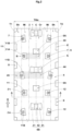
- FIG. 2 is a development of the tread portion 2 of the tire 1 laid out to be flat.
- FIG. 1 corresponds to a cross-sectional view taken along a line A-A in FIG. 2 .
- the "standardized state” represents a state in which a tire is fitted on a standardized rim and is inflated to a standardized internal pressure and no load is applied to the tire when the tire is a tire for which various standards are defined.
- the standardized state represents a standard use state, corresponding to a purpose of use of the tire, in which no load is applied to the tire.
- the dimensions of the components and the like are represented by values measured in the standardized state.
- the "standardized rim” represents a rim that is defined by a standard for each tire, in a standard system including the standard on which the tire is based, and is, for example, “standard rim” in the JATMA standard, "Design Rim” in the TRA standard, or “Measuring Rim” in the ETRTO standard.
- the "standardized internal pressure” represents an air pressure that is defined by a standard for each tire, in a standard system including the standard on which the tire is based, and is “maximum air pressure” in the JATMA standard, the maximum value recited in the table "TIRE LOAD LIMITS AT VARIOUS COLD INFLATION PRESSURES" in the TRA standard, or "INFLATION PRESSURE” in the ETRTO standard.
- the tire 1 of the present embodiment as shown in FIG. 1 is preferably used as a tire for motocross racing, for example.
- the tire 1 of the present embodiment is preferably used as a tire for the rear wheel of a motocross vehicle, for example.
- the present invention is not limited thereto.
- the tread portion 2 has an outer surface curved in an arc shape that is convex outward in a tire radial direction, on a transverse cross-section thereof.
- the tire 1 of the present embodiment for example, includes a carcass and a tread reinforcing layer (not shown).
- a carcass for example, includes a carcass and a tread reinforcing layer (not shown).
- tread reinforcing layer for these components, known configurations are used as appropriate.
- the tread portion 2 of the tire 1 of the present invention includes a directional pattern having a designated rotation direction R.
- the rotation direction R is indicated, for example, on each sidewall portion 3 (shown in FIG. 1 ) by characters or symbols.
- the present invention is not limited thereto.
- the tread portion 2 is, for example, divided into a crown region Cr, middle regions Mi, and shoulder regions Sh.
- the crown region Cr is a region centered at a tire equator C and having a width that is 1/3 of a tread development width TWe.
- Each shoulder region Sh is a region having a width that is 1/6 of the tread development width TWe and extending from a first tread end T1 or a second tread end T2 toward the tire equator C side.
- Each middle region Mi is a region between the crown region Cr and the shoulder region Sh.
- the tread development width TWe is a distance from the first tread end T1 to the second tread end T2 in a tire axial direction when the tread portion 2 is laid out to be flat.
- the first tread end T1 and the second tread end T2 each correspond to the end edges, on the outer side in the tire axial direction, of blocks included in a block row located on the outermost side in the tire axial direction, among blocks disposed in the tread portion 2.
- the first tread end T1 is shown as a tread end on the left side and the second tread end T2 is shown as a tread end on the right side, but the present invention is not limited thereto.
- the tread portion 2 includes a base surface 4, and a plurality of blocks 5 raised outward in the tire radial direction from the base surface 4.
- a tread surface, facing outward in the tire radial direction, of each block 5 extends parallel to the base surface 4.
- the blocks 5 of the present embodiment include a plurality of crown blocks 6 on the tire equator C side, a plurality of shoulder blocks 8 on the first tread end T1 or the second tread end T2 side, and a plurality of middle blocks 7 disposed between the crown blocks 6 and the shoulder blocks 8.
- the centroid of the tread surface thereof meaning a surface that comes into contact with a flat surface when the tire is made to run thereon, the same applies below
- on the outer side in the tire radial direction is located within the crown region Cr.
- centroid of the tread surface thereof is located within the middle region Mi.
- centroid of the tread surface thereof is located within the shoulder region Sh.
- the centroid means the centroid of the tread surface in a state where all the grooves are filled.
- the tread portion 2 of the present invention includes a plurality of first blocks 11 disposed on the first tread end T1 side with respect to the tire equator C.
- the first blocks 11 of the present embodiment are configured as the middle blocks 7 disposed in the middle region Mi, but the first blocks 11 may be disposed in the shoulder region Sh.
- the first blocks 11 of the present embodiment include a plurality of first inner blocks 11A disposed relatively on the tire equator C side, and a plurality of first outer blocks 11B disposed on the first tread end T1 side with respect to the first inner blocks 11A. Whereas the entire first inner blocks 11A are disposed in the middle region Mi, the first outer blocks 11B are each disposed so as to be located in both the middle region Mi and the shoulder region Sh. In a preferable mode, the first inner blocks 11A and the first outer blocks 11B alternate in a tire circumferential direction. However, the present invention is not limited thereto.
- the configuration of each first block 11 the configuration of the first inner block 11A will be mainly described as an example.
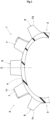
- FIG. 3 shows an enlarged perspective view of the first block 11
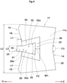
- FIG. 4 shows an enlarged plan view of the first block 11.
- an enlarged plan view of the tread surface of the block as shown in FIG. 4 clearly illustrates the contour of the tread surface of the block mainly.
- the configurations of side surfaces or the root of the block may be omitted, even if the configuration thereof can be observed in a plan view of the block.
- the plurality of first blocks 11 each include a tread surface 11s facing outward in the tire radial direction, and an outer side wall 13 on the first tread end T1 side.
- the tread surface 11s includes an outer edge 15 between the tread surface 11s and the outer side wall 13.
- the outer edge 15 corresponds to a ridgeline formed between the tread surface 11s and the outer side wall 13.
- the outer edge 15 corresponds to a set of the center positions of arcs observed in cross-sections of the curved surface.
- the outer edge 15 includes a protrusion 18, a first portion 16, and a second portion 17.
- the protrusion 18 protrudes locally on the first tread end T1 side.
- the first portion 16 is located on one side in the tire circumferential direction of the protrusion 18.
- the second portion 17 is located on the other side in the tire circumferential direction of the protrusion 18.
- the first portion 16 and the second portion 17 are disposed so as to form a minor angle therebetween on the first tread end T1 side. That is, of a conjugate angle on the tire equator C side and a conjugate angle on the first tread end T1 side that are formed by the first portion 16 and the second portion 17, the conjugate angle on the first tread end T1 side is an angle smaller than 180°.
- the tire 1 of the present invention can achieve excellent rolling characteristics.
- the rolling characteristics mean overall impression that a driver can feel when rolling a vehicle during cornering. Accordingly, the rolling characteristics include at least lightness during rolling, response during rolling, and the like.
- the lightness during rolling means characteristics that the vehicle can be rolled with smaller force.
- the response during rolling means characteristics that the driver receives moderate reaction force from the vehicle during rolling and the reaction force is linear. "Excellent rolling characteristics" means that these characteristics are exhibited in a well-balanced manner, so that an excellent result can be expected in motocross racing or the like.
- the tread surface 11s of the first block 11 includes the protrusion 18, whereby deformation of the first block 11 (deformation caused when the block falls down excessively on the first tread end side) of the first block 11 can be inhibited during rolling. Accordingly, the driver can receive sufficient response during rolling.
- the first portion 16 and the second portion 17 of the outer edge 15 are disposed so as to form a minor angle therebetween on the first tread end T1 side. Accordingly, when the outer edge 15 comes into contact with the ground during cornering, the outer edge 15 and the outer side wall 13 are moderately deformed such that the minor angle becomes larger.
- Such an effect serves to enhance lightness during rolling, and, in cooperation with the above-described effect of the protrusion 18, excellent rolling characteristics can be achieved.
- the outer side wall 13 of the present embodiment includes a first side wall portion 21, a second side wall portion 22, and a protruding side wall 23 that are each planar and are respectively connected to the first portion 16, the second portion 17, and the protrusion 18.
- the first side wall portion 21 extends from the first portion 16 toward the root of the first block 11.
- the second side wall portion 22 extends from the second portion 17 toward the above-mentioned root.
- the protruding side wall 23 extends from the protrusion 18 toward the root of the first block 11.
- the outer side wall 13 of the present embodiment has a shape that is recessed on the tire equator C side and formed by the first side wall portion 21 and the second side wall portion 22.
- the protruding side wall 23 protrudes locally from the bottom portion of the outer side wall 13.
- the tread surface 11s of the first block 11 of the present embodiment is provided with one narrow groove 25.
- the narrow groove 25 has a semi-annular shape with both ends opened at the outer side wall 13.
- the first block 11 includes a protruding block piece 26 surrounded by the narrow groove 25.
- the protruding block piece 26 includes the protrusion 18.
- the present invention is not limited thereto. Even if the narrow groove 25 and the protruding block piece 26 are not formed, the above-described effect can be expected as long as the tread surface 11s includes the above-described first portion 16, second portion 17, and protrusion 18.
- the protrusion 18 protrudes outward in a block width direction by 1 mm or more from the first portion 16 and the second portion 17. That is, a distance L1 in the tire axial direction from the end on the protrusion 18 side of the first portion 16 or the second portion 17 to the end on the first tread end T1 side of the protrusion 18 is 1 mm or more. In a preferable mode, the distance L1 is 1.0 to 3.0 mm. Such a configuration facilitates moderate deformation of the part around the protrusion 18, and mud and dirt attached around the first block 11 can be effectively removed during running on a muddy road, for example.
- a maximum length L3 in the tire circumferential direction of the protruding side wall 23 is, for example, 5% to 75% of a maximum length L2 in the tire circumferential direction of the tread surface 11s of the first block 11.
- the length L3 of the protruding side wall 23 is 5% to 25% of the length L2 of the tread surface 11s of the first block 11, and more preferably 5% to 15% thereof. Accordingly, the protruding block piece 26 has appropriate stiffness to exert great reaction force in the tire circumferential direction, so that traction performance is improved.
- an angle ⁇ 1 which is the minor angle between the first portion 16 and the second portion 17 is, for example, 140 to 160°. Accordingly, the above-described effect is reliably achieved.
- FIG. 5 is an enlarged side view (side view observed in the direction of an arrow B in FIG. 2 ) of the first block 11 illustrating the first portion 16, the second portion 17, and the protrusion 18.
- the protrusion 18 includes a portion that is more protruded in the height direction of the first block 11 than the first portion 16 and second portion 17.
- the entire protrusion 18 is more protruded in the height direction than the first portion 16 and the second portion 17.
- the entire tread surface 26s of the protruding block piece 26 is more protruded in the height direction than the other parts of the first block 11.
- a maximum height h1 measured at the protrusion 18 of the first block 11 is 102% to 120% of a maximum height h2 measured at the first portion 16 or the second portion 17 of the first block 11.
- the relationship between the height of the protrusion 18 and the height of the first portion 16 or the second portion 17 is applied to the relationship between the height of the protruding block piece 26 measured at the tread surface 26s and the height of the first block 11 measured at the tread surface 11s except for the tread surface 26s.
- the tread surface 26s of the protruding block piece 26 includes a constant width portion 31 that extends toward the tire equator C side so as to have a width equal to the length of the protrusion 18, and a widening portion 32 of which a width in the tire circumferential direction increases toward the tire equator C side.
- the widening portion 32 is largely surrounded by the narrow groove 25.
- most of the constant width portion 31 (80% or more of the area of the constant width portion 31) is located on the first tread end T1 side with respect to a virtual line (not shown) obtained by connecting the end on the protrusion 18 side of the first portion 16 and the end on the protrusion 18 side of the second portion 17.
- the protruding block piece 26 having such a tread surface 26s allows the edge of the constant width portion 31 to provide a grip force in the tire circumferential direction, thereby enhancing the traction performance.
- the area of the widening portion 32 is preferably larger than that of the constant width portion 31.
- the area of the widening portion 32 is, for example, 3.0 to 4.0 times that of the constant width portion 31. Accordingly, damage to the protruding block piece 26 is effectively reduced.
- the widening portion 32 includes two edges 32e that linearly extend.
- the two edges 32e extend non-parallel to each other.
- An angle ⁇ 2 between the two edges 32e is, for example, 20 to 40°, and preferably 25 to 35°.
- Such a widening portion 32 can prevent excessive falling of the protruding block piece 26 on the first tread end T1 side and can improve response during rolling.
- the narrow groove 25 includes two lateral groove portions 35 and one longitudinal groove portion 36.
- Each of the two lateral groove portions 35 extends from the outer side wall 13 toward the tire equator C side.
- the longitudinal groove portion 36 extends from an end portion on the tire equator C side of one lateral groove portion 35 to an end portion on the tire equator C side of the other lateral groove portion 35.
- each of the lateral groove portions 35 and the longitudinal groove portion 36 linearly extends.
- Each lateral groove portion 35 and the longitudinal groove portion 36 are connected so as to form acute angles therebetween.
- the two lateral groove portions 35 extend so as to be inclined in a direction away from each other toward the tire equator C side.
- An angle between the two lateral groove portions 35 is substantially the same as the angle ⁇ 2 between the two edges 32e of the widening portion 32.
- the longitudinal groove portion 36 is preferably disposed at a center portion of the first block 11. From this viewpoint, in the present embodiment, in a case where, in a state where the narrow groove 25 is filled, the first block 11 is divided into three regions having equal areas by two virtual straight lines extending parallel with the tire circumferential direction, at least a part of the longitudinal groove portion 36 of the tread surface 11s is positioned at a center region of the three regions. In a more preferable mode, the entire longitudinal groove portion 36 is positioned at the center region of the three regions. Such positioning of the longitudinal groove portion 36 serves to inhibit uneven wear of the first block 11.
- a maximum groove width W1 of the narrow groove 25 is preferably 70% to 90% of the maximum length L3 in the tire circumferential direction of the protruding side wall 23. Such a narrow groove 25 inhibits uneven wear of the block and serves to enhance grip performance on a muddy road.
- the first block 11 includes an inner side wall 14 on the tire equator C side.
- the inner side wall 14 is preferably recessed toward the first tread end T1 side.
- the tread surface 11s includes an inner edge 20 between the tread surface 11s and the inner side wall 14, and the inner edge 20 is composed of two linear edges disposed so as to form a minor angle therebetween on the tire equator C side.
- the inner side wall 14 includes two flat surfaces (not shown) extending from the two straight-line edges to the root of the first block 11. Such an inner side wall 14 provides great reaction force in the tire axial direction particularly during cornering on a muddy road, thereby enhancing cornering performance.
- an angle ⁇ 3 which is the minor angle formed by the inner edge 20 is larger than the angle ⁇ 1 (shown in FIG. 2 ) which is the minor angle between the first portion 16 and the second portion 17 of the outer edge 15.
- the angle ⁇ 3 which is the minor angle is 150 to 170°. Accordingly, the change in the response during rolling becomes linear, thereby further improving rolling characteristics.
- FIG. 6 is an enlarged plan view of the first outer block 11B.
- the above-described characteristics of the first block 11 can be applied to the first outer block 11B as shown in FIG. 6 .
- the first outer block 11B is formed as a longitudinally elongated shape in the tire circumferential direction, as compared to the first inner block 11A. Accordingly, as for an aspect ratio obtained by dividing the maximum length in the tire circumferential direction of the tread surface 1 1s by the maximum length in the tire axial direction of the tread surface 11s, the aspect ratio of the first outer block 11B is larger than the aspect ratio of the first inner block 11A. Specifically, while the aspect ratio of the first inner block 11A is 1.25 to 1.40, the aspect ratio of the first outer block 11B is 1.40 to 1.50. Accordingly, the first outer block 11B can provide great reaction force in the tire axial direction, thereby improving cornering performance.
- an angle ⁇ 4 which is a minor angle between the first portion 16 and the second portion 17 of the outer edge 15 of the first outer block 11B is preferably larger than the angle ⁇ 1 of the first inner block 11A.
- the angle ⁇ 4 is 165 to 170°, and the difference between the angle ⁇ 4 and the angle ⁇ 1 is 10 to 25°. Accordingly, excellent rolling characteristics can be achieved in various road surface conditions.
- an angle ⁇ 5 which is a minor angle formed by an inner edge 20 of the first outer block 11B as shown in FIG. 6 is preferably larger than the angle ⁇ 3 (shown in FIG. 4 ) which is the minor angle formed by the inner edge 20 of the first inner block 11A.
- the angle ⁇ 5 is 165 to 175°, and the difference between the angle ⁇ 3 and the angle ⁇ 5 is 5 to 10°.
- first crown blocks 6A and second crown blocks 6B having shapes different from each other alternate in the tire circumferential direction.
- the first crown blocks 6A each have a substantially rectangular tread surface, and no groove is provided to the tread surface.
- the second crown blocks 6B each include two block pieces 41 and a tie bar 42 connecting the block pieces 41.
- the crown blocks 6 are not limited thereto.
- a virtual region 43 obtained by extending the first inner block 11A in a direction parallel with the tire axial direction toward the tire equator C side is preferably overlapped with at least a part of the first crown block 6A.
- a virtual region 44 obtained by extending the first outer block 11B parallel with the tire axial direction toward the tire equator C side is preferably overlapped with at least a part of the second crown block 6B.
- the crown blocks 6 and the first blocks 11 cooperate to provide great reaction force in the tire circumferential direction during running on a muddy road, thereby serving to improve traction performance.
- each shoulder region Sh a plurality of shoulder blocks 8 are provided.
- none of the virtual regions 45 obtained by extending the first blocks 11 (including both the first inner block 11A and the first outer block 11B) parallel with the tire axial direction toward the first tread end T1 side is overlapped with the shoulder block 8.
- dirt and mud are less likely to be retained between the first blocks 11 and the shoulder blocks 8, thereby continuously achieving excellent rolling characteristics.
- the tread portion 2 of the present embodiment includes a plurality of second blocks 12 disposed on the second tread end T2 side with respect to the tire equator C.
- the second blocks 12 have substantially the same characteristics as the above-described first blocks 11.
- a rear wheel tire for a motorcycle for running on rough terrain having the basic pattern in FIG. 2 was produced as a test tire.
- a tire having a tread pattern shown in FIG. 7 was produced as a test tire.
- the tire of the comparative example is based on the tread pattern shown in FIG. 2 , but, instead of the first blocks and the second blocks, blocks a which do not have the characteristics of the present invention are disposed.
- the tire of the comparative example is substantially the same as the tire of the example, except for the above matters. For these test tires, rolling characteristics were tested.
- the specifications common to the test tires and the test method are as follows.
- the present invention includes the following aspects.
- a motorcycle tire for running on rough terrain including a tread portion, wherein
- the motorcycle tire for running on rough terrain according to Present Invention 1, wherein in a planar view of the tread surface, the protrusion protrudes outward in a block width direction by 1 mm or more from the first portion and the second portion.
- the protrusion includes a portion that is more protruded in a height direction of the first block than the first portion and second portion.
- a maximum height measured at the protrusion of the first block is 102% to 120% of a maximum height measured at the first portion or the second portion of the first block.
Landscapes
- Engineering & Computer Science (AREA)
- Mechanical Engineering (AREA)
- Tires In General (AREA)
Abstract
Description
- The present invention relates to a motorcycle tire for running on rough terrain.
- In
Japanese Laid-Open Patent Publication No. 2019-108037 - In the above-described tire, there is room for improvement in rolling characteristics (characteristics including lightness during rolling and response during rolling) when a vehicle is leaned during cornering.
- The present invention has been made in view of the above circumstances, and the main object of the present invention is to provide a motorcycle tire for running on rough terrain capable of achieving excellent rolling characteristics.
- The present invention is directed to a motorcycle tire for running on rough terrain, the motorcycle tire including a tread portion, wherein the tread portion includes a tire equator, a first tread end, and a plurality of first blocks disposed on the first tread end side with respect to the tire equator, each of the plurality of first blocks includes a tread surface facing outward in a tire radial direction and an outer side wall on the first tread end side, the tread surface includes an outer edge between the tread surface and the outer side wall, the outer edge includes a protrusion protruding locally on the first tread end side, a first portion located on one side in a tire circumferential direction of the protrusion, and a second portion located on another side in the tire circumferential direction of the protrusion, and the first portion and the second portion are disposed so as to form a minor angle therebetween on the first tread end side.
- As a result of adopting the above configuration, the motorcycle tire for running on rough terrain according to the present invention can achieve excellent rolling characteristics.
-
-
FIG. 1 is a cross-sectional view of a tread portion of a motorcycle tire for running on rough terrain according to the present embodiment; -
FIG. 2 is a development of the tread portion inFIG. 1 ; -
FIG. 3 is an enlarged perspective view of a first block inFIG. 2 ; -
FIG. 4 is an enlarged plan view of the first block inFIG. 2 ; -
FIG. 5 is an enlarged side view illustrating a first portion, a second portion, and a protrusion of the first block; -
FIG. 6 is an enlarged plan view of a first outer block inFIG. 2 ; and -
FIG. 7 is a development of a tread portion of a tire of a comparative example. - Hereinafter, an embodiment of the present invention will be described with reference to the drawings.
FIG. 1 is a cross-sectional view of atread portion 2 of a motorcycle tire (hereinafter, also referred to simply as "tire") 1 for running on rough terrain according to the present embodiment in a standardized state.FIG. 2 is a development of thetread portion 2 of thetire 1 laid out to be flat.FIG. 1 corresponds to a cross-sectional view taken along a line A-A inFIG. 2 . - The "standardized state" represents a state in which a tire is fitted on a standardized rim and is inflated to a standardized internal pressure and no load is applied to the tire when the tire is a tire for which various standards are defined. For tires for which various standards are not defined, the standardized state represents a standard use state, corresponding to a purpose of use of the tire, in which no load is applied to the tire. In the present application, unless otherwise specified, the dimensions of the components and the like are represented by values measured in the standardized state.
- The "standardized rim" represents a rim that is defined by a standard for each tire, in a standard system including the standard on which the tire is based, and is, for example, "standard rim" in the JATMA standard, "Design Rim" in the TRA standard, or "Measuring Rim" in the ETRTO standard.
- The "standardized internal pressure" represents an air pressure that is defined by a standard for each tire, in a standard system including the standard on which the tire is based, and is "maximum air pressure" in the JATMA standard, the maximum value recited in the table "TIRE LOAD LIMITS AT VARIOUS COLD INFLATION PRESSURES" in the TRA standard, or "INFLATION PRESSURE" in the ETRTO standard.
- The
tire 1 of the present embodiment as shown inFIG. 1 is preferably used as a tire for motocross racing, for example. Thetire 1 of the present embodiment is preferably used as a tire for the rear wheel of a motocross vehicle, for example. However, the present invention is not limited thereto. In thetire 1 of the present embodiment, thetread portion 2 has an outer surface curved in an arc shape that is convex outward in a tire radial direction, on a transverse cross-section thereof. - The
tire 1 of the present embodiment, for example, includes a carcass and a tread reinforcing layer (not shown). For these components, known configurations are used as appropriate. - As shown in
FIG. 2 , thetread portion 2 of thetire 1 of the present invention includes a directional pattern having a designated rotation direction R. The rotation direction R is indicated, for example, on each sidewall portion 3 (shown inFIG. 1 ) by characters or symbols. However, the present invention is not limited thereto. - The
tread portion 2 is, for example, divided into a crown region Cr, middle regions Mi, and shoulder regions Sh. - The crown region Cr is a region centered at a tire equator C and having a width that is 1/3 of a tread development width TWe. Each shoulder region Sh is a region having a width that is 1/6 of the tread development width TWe and extending from a first tread end T1 or a second tread end T2 toward the tire equator C side. Each middle region Mi is a region between the crown region Cr and the shoulder region Sh.
- The tread development width TWe is a distance from the first tread end T1 to the second tread end T2 in a tire axial direction when the
tread portion 2 is laid out to be flat. The first tread end T1 and the second tread end T2 each correspond to the end edges, on the outer side in the tire axial direction, of blocks included in a block row located on the outermost side in the tire axial direction, among blocks disposed in thetread portion 2. InFIG. 2 , the first tread end T1 is shown as a tread end on the left side and the second tread end T2 is shown as a tread end on the right side, but the present invention is not limited thereto. - The
tread portion 2 includes abase surface 4, and a plurality ofblocks 5 raised outward in the tire radial direction from thebase surface 4. A tread surface, facing outward in the tire radial direction, of eachblock 5 extends parallel to thebase surface 4. Theblocks 5 of the present embodiment include a plurality of crown blocks 6 on the tire equator C side, a plurality ofshoulder blocks 8 on the first tread end T1 or the second tread end T2 side, and a plurality ofmiddle blocks 7 disposed between the crown blocks 6 and theshoulder blocks 8. In each crown block 6, the centroid of the tread surface thereof (meaning a surface that comes into contact with a flat surface when the tire is made to run thereon, the same applies below) on the outer side in the tire radial direction is located within the crown region Cr. In eachmiddle block 7, the centroid of the tread surface thereof is located within the middle region Mi. In eachshoulder block 8, the centroid of the tread surface thereof is located within the shoulder region Sh. When the tread surface is provided with grooves, the centroid means the centroid of the tread surface in a state where all the grooves are filled. - The
tread portion 2 of the present invention includes a plurality offirst blocks 11 disposed on the first tread end T1 side with respect to the tire equator C. Thefirst blocks 11 of the present embodiment are configured as themiddle blocks 7 disposed in the middle region Mi, but thefirst blocks 11 may be disposed in the shoulder region Sh. - The
first blocks 11 of the present embodiment include a plurality of firstinner blocks 11A disposed relatively on the tire equator C side, and a plurality of firstouter blocks 11B disposed on the first tread end T1 side with respect to the firstinner blocks 11A. Whereas the entire firstinner blocks 11A are disposed in the middle region Mi, the firstouter blocks 11B are each disposed so as to be located in both the middle region Mi and the shoulder region Sh. In a preferable mode, the firstinner blocks 11A and the firstouter blocks 11B alternate in a tire circumferential direction. However, the present invention is not limited thereto. Hereinafter, as the configuration of eachfirst block 11, the configuration of the firstinner block 11A will be mainly described as an example. -
FIG. 3 shows an enlarged perspective view of thefirst block 11, andFIG. 4 shows an enlarged plan view of thefirst block 11. In the present specification, an enlarged plan view of the tread surface of the block as shown inFIG. 4 clearly illustrates the contour of the tread surface of the block mainly. However, the configurations of side surfaces or the root of the block may be omitted, even if the configuration thereof can be observed in a plan view of the block. - As shown in
FIG. 3 andFIG. 4 , the plurality offirst blocks 11 each include atread surface 11s facing outward in the tire radial direction, and anouter side wall 13 on the first tread end T1 side. Thetread surface 11s includes anouter edge 15 between thetread surface 11s and theouter side wall 13. Theouter edge 15 corresponds to a ridgeline formed between thetread surface 11s and theouter side wall 13. In the case where thetread surface 11s and theouter side wall 13 are connected so as to form a minute curved surface, theouter edge 15 corresponds to a set of the center positions of arcs observed in cross-sections of the curved surface. - As shown in
FIG. 3 , theouter edge 15 includes aprotrusion 18, afirst portion 16, and asecond portion 17. Theprotrusion 18 protrudes locally on the first tread end T1 side. Thefirst portion 16 is located on one side in the tire circumferential direction of theprotrusion 18. Thesecond portion 17 is located on the other side in the tire circumferential direction of theprotrusion 18. - As shown in
FIG. 4 , thefirst portion 16 and thesecond portion 17 are disposed so as to form a minor angle therebetween on the first tread end T1 side. That is, of a conjugate angle on the tire equator C side and a conjugate angle on the first tread end T1 side that are formed by thefirst portion 16 and thesecond portion 17, the conjugate angle on the first tread end T1 side is an angle smaller than 180°. As a result of adopting the above configuration, thetire 1 of the present invention can achieve excellent rolling characteristics. - The rolling characteristics mean overall impression that a driver can feel when rolling a vehicle during cornering. Accordingly, the rolling characteristics include at least lightness during rolling, response during rolling, and the like. The lightness during rolling means characteristics that the vehicle can be rolled with smaller force. The response during rolling means characteristics that the driver receives moderate reaction force from the vehicle during rolling and the reaction force is linear. "Excellent rolling characteristics" means that these characteristics are exhibited in a well-balanced manner, so that an excellent result can be expected in motocross racing or the like.
- The reason why the
tire 1 of the present invention can achieve excellent rolling characteristics is as follows. In the present invention, thetread surface 11s of thefirst block 11 includes theprotrusion 18, whereby deformation of the first block 11 (deformation caused when the block falls down excessively on the first tread end side) of thefirst block 11 can be inhibited during rolling. Accordingly, the driver can receive sufficient response during rolling. In addition, in thetire 1 of the present invention, thefirst portion 16 and thesecond portion 17 of theouter edge 15 are disposed so as to form a minor angle therebetween on the first tread end T1 side. Accordingly, when theouter edge 15 comes into contact with the ground during cornering, theouter edge 15 and theouter side wall 13 are moderately deformed such that the minor angle becomes larger. Such an effect serves to enhance lightness during rolling, and, in cooperation with the above-described effect of theprotrusion 18, excellent rolling characteristics can be achieved. - Hereinafter, more detailed configurations of the present embodiment will be described. The configurations described below show a specific mode of the present embodiment. Therefore, it is needless to say that the present invention can achieve the above-described effect even when the configurations described below are not provided. In addition, even when any one of the configurations described below is independently applied to the tire according to the present invention having the above-described characteristics, performance improvement corresponding to each configuration can be expected. Furthermore, when some of the configurations described below are applied in combination, complex performance improvement corresponding to each configuration can be expected.
- As shown in
FIG. 3 , thefirst portion 16, thesecond portion 17, and theprotrusion 18 linearly extend. Theouter side wall 13 of the present embodiment includes a firstside wall portion 21, a secondside wall portion 22, and a protrudingside wall 23 that are each planar and are respectively connected to thefirst portion 16, thesecond portion 17, and theprotrusion 18. The firstside wall portion 21 extends from thefirst portion 16 toward the root of thefirst block 11. The secondside wall portion 22 extends from thesecond portion 17 toward the above-mentioned root. The protrudingside wall 23 extends from theprotrusion 18 toward the root of thefirst block 11. Theouter side wall 13 of the present embodiment has a shape that is recessed on the tire equator C side and formed by the firstside wall portion 21 and the secondside wall portion 22. In addition, the protrudingside wall 23 protrudes locally from the bottom portion of theouter side wall 13. - As shown in
FIG. 4 , thetread surface 11s of thefirst block 11 of the present embodiment is provided with onenarrow groove 25. Thenarrow groove 25 has a semi-annular shape with both ends opened at theouter side wall 13. In addition, thefirst block 11 includes a protrudingblock piece 26 surrounded by thenarrow groove 25. In the present embodiment, the protrudingblock piece 26 includes theprotrusion 18. However, the present invention is not limited thereto. Even if thenarrow groove 25 and the protrudingblock piece 26 are not formed, the above-described effect can be expected as long as thetread surface 11s includes the above-describedfirst portion 16,second portion 17, andprotrusion 18. - In a planar view of the
tread surface 11s, theprotrusion 18 protrudes outward in a block width direction by 1 mm or more from thefirst portion 16 and thesecond portion 17. That is, a distance L1 in the tire axial direction from the end on theprotrusion 18 side of thefirst portion 16 or thesecond portion 17 to the end on the first tread end T1 side of theprotrusion 18 is 1 mm or more. In a preferable mode, the distance L1 is 1.0 to 3.0 mm. Such a configuration facilitates moderate deformation of the part around theprotrusion 18, and mud and dirt attached around thefirst block 11 can be effectively removed during running on a muddy road, for example. - A maximum length L3 in the tire circumferential direction of the protruding
side wall 23 is, for example, 5% to 75% of a maximum length L2 in the tire circumferential direction of thetread surface 11s of thefirst block 11. In a preferable mode, the length L3 of the protrudingside wall 23 is 5% to 25% of the length L2 of thetread surface 11s of thefirst block 11, and more preferably 5% to 15% thereof. Accordingly, the protrudingblock piece 26 has appropriate stiffness to exert great reaction force in the tire circumferential direction, so that traction performance is improved. - As shown in
FIG. 2 , an angle θ1 which is the minor angle between thefirst portion 16 and thesecond portion 17 is, for example, 140 to 160°. Accordingly, the above-described effect is reliably achieved. -
FIG. 5 is an enlarged side view (side view observed in the direction of an arrow B inFIG. 2 ) of thefirst block 11 illustrating thefirst portion 16, thesecond portion 17, and theprotrusion 18. As shown inFIG. 5 , theprotrusion 18 includes a portion that is more protruded in the height direction of thefirst block 11 than thefirst portion 16 andsecond portion 17. In a preferable mode, theentire protrusion 18 is more protruded in the height direction than thefirst portion 16 and thesecond portion 17. In a more preferable mode, theentire tread surface 26s of the protrudingblock piece 26 is more protruded in the height direction than the other parts of thefirst block 11. A maximum height h1 measured at theprotrusion 18 of thefirst block 11 is 102% to 120% of a maximum height h2 measured at thefirst portion 16 or thesecond portion 17 of thefirst block 11. In the present embodiment, the relationship between the height of theprotrusion 18 and the height of thefirst portion 16 or thesecond portion 17 is applied to the relationship between the height of the protrudingblock piece 26 measured at thetread surface 26s and the height of thefirst block 11 measured at thetread surface 11s except for thetread surface 26s. With such afirst block 11, rolling characteristics are improved, great grip force is exerted by the protrudingblock piece 26, and traction performance and cornering performance are also improved. - As shown in
FIG. 4 , thetread surface 26s of the protrudingblock piece 26 includes aconstant width portion 31 that extends toward the tire equator C side so as to have a width equal to the length of theprotrusion 18, and a wideningportion 32 of which a width in the tire circumferential direction increases toward the tire equator C side. In the present embodiment, in a planar view of thetread surface 11s of thefirst block 11, the wideningportion 32 is largely surrounded by thenarrow groove 25. Also, in the planar view, most of the constant width portion 31 (80% or more of the area of the constant width portion 31) is located on the first tread end T1 side with respect to a virtual line (not shown) obtained by connecting the end on theprotrusion 18 side of thefirst portion 16 and the end on theprotrusion 18 side of thesecond portion 17. The protrudingblock piece 26 having such atread surface 26s allows the edge of theconstant width portion 31 to provide a grip force in the tire circumferential direction, thereby enhancing the traction performance. - The area of the widening
portion 32 is preferably larger than that of theconstant width portion 31. The area of the wideningportion 32 is, for example, 3.0 to 4.0 times that of theconstant width portion 31. Accordingly, damage to the protrudingblock piece 26 is effectively reduced. - The widening
portion 32 includes twoedges 32e that linearly extend. The twoedges 32e extend non-parallel to each other. An angle θ2 between the twoedges 32e is, for example, 20 to 40°, and preferably 25 to 35°. Such a wideningportion 32 can prevent excessive falling of the protrudingblock piece 26 on the first tread end T1 side and can improve response during rolling. - The
narrow groove 25 includes twolateral groove portions 35 and onelongitudinal groove portion 36. Each of the twolateral groove portions 35 extends from theouter side wall 13 toward the tire equator C side. Thelongitudinal groove portion 36 extends from an end portion on the tire equator C side of onelateral groove portion 35 to an end portion on the tire equator C side of the otherlateral groove portion 35. In addition, each of thelateral groove portions 35 and thelongitudinal groove portion 36 linearly extends. Eachlateral groove portion 35 and thelongitudinal groove portion 36 are connected so as to form acute angles therebetween. - The two
lateral groove portions 35 extend so as to be inclined in a direction away from each other toward the tire equator C side. An angle between the twolateral groove portions 35 is substantially the same as the angle θ2 between the twoedges 32e of the wideningportion 32. - The
longitudinal groove portion 36 is preferably disposed at a center portion of thefirst block 11. From this viewpoint, in the present embodiment, in a case where, in a state where thenarrow groove 25 is filled, thefirst block 11 is divided into three regions having equal areas by two virtual straight lines extending parallel with the tire circumferential direction, at least a part of thelongitudinal groove portion 36 of thetread surface 11s is positioned at a center region of the three regions. In a more preferable mode, the entirelongitudinal groove portion 36 is positioned at the center region of the three regions. Such positioning of thelongitudinal groove portion 36 serves to inhibit uneven wear of thefirst block 11. - A maximum groove width W1 of the
narrow groove 25 is preferably 70% to 90% of the maximum length L3 in the tire circumferential direction of the protrudingside wall 23. Such anarrow groove 25 inhibits uneven wear of the block and serves to enhance grip performance on a muddy road. - The
first block 11 includes aninner side wall 14 on the tire equator C side. Theinner side wall 14 is preferably recessed toward the first tread end T1 side. Specifically, thetread surface 11s includes aninner edge 20 between thetread surface 11s and theinner side wall 14, and theinner edge 20 is composed of two linear edges disposed so as to form a minor angle therebetween on the tire equator C side. In addition, theinner side wall 14 includes two flat surfaces (not shown) extending from the two straight-line edges to the root of thefirst block 11. Such aninner side wall 14 provides great reaction force in the tire axial direction particularly during cornering on a muddy road, thereby enhancing cornering performance. - In a preferable mode, an angle θ3 which is the minor angle formed by the
inner edge 20 is larger than the angle θ1 (shown inFIG. 2 ) which is the minor angle between thefirst portion 16 and thesecond portion 17 of theouter edge 15. Specifically, the angle θ3 which is the minor angle is 150 to 170°. Accordingly, the change in the response during rolling becomes linear, thereby further improving rolling characteristics. -
FIG. 6 is an enlarged plan view of the firstouter block 11B. The above-described characteristics of the first block 11 (firstinner block 11A) can be applied to the firstouter block 11B as shown inFIG. 6 . - The first
outer block 11B is formed as a longitudinally elongated shape in the tire circumferential direction, as compared to the firstinner block 11A. Accordingly, as for an aspect ratio obtained by dividing the maximum length in the tire circumferential direction of thetread surface 1 1s by the maximum length in the tire axial direction of thetread surface 11s, the aspect ratio of the firstouter block 11B is larger than the aspect ratio of the firstinner block 11A. Specifically, while the aspect ratio of the firstinner block 11A is 1.25 to 1.40, the aspect ratio of the firstouter block 11B is 1.40 to 1.50. Accordingly, the firstouter block 11B can provide great reaction force in the tire axial direction, thereby improving cornering performance. - As shown in
FIG. 2 , an angle θ4 which is a minor angle between thefirst portion 16 and thesecond portion 17 of theouter edge 15 of the firstouter block 11B is preferably larger than the angle θ1 of the firstinner block 11A. Specifically, the angle θ4 is 165 to 170°, and the difference between the angle θ4 and the angle θ1 is 10 to 25°. Accordingly, excellent rolling characteristics can be achieved in various road surface conditions. - From the same viewpoint, an angle θ5 which is a minor angle formed by an
inner edge 20 of the firstouter block 11B as shown inFIG. 6 is preferably larger than the angle θ3 (shown inFIG. 4 ) which is the minor angle formed by theinner edge 20 of the firstinner block 11A. Specifically, the angle θ5 is 165 to 175°, and the difference between the angle θ3 and the angle θ5 is 5 to 10°. - As shown in
FIG. 2 , in the crown region Cr, the plurality of crown blocks 6 are provided, for example. In the present embodiment, first crown blocks 6A and second crown blocks 6B having shapes different from each other alternate in the tire circumferential direction. - The first crown blocks 6A each have a substantially rectangular tread surface, and no groove is provided to the tread surface. The second crown blocks 6B each include two
block pieces 41 and atie bar 42 connecting theblock pieces 41. However, the crown blocks 6 are not limited thereto. - In a planar view of the
tread portion 2, avirtual region 43 obtained by extending the firstinner block 11A in a direction parallel with the tire axial direction toward the tire equator C side is preferably overlapped with at least a part of thefirst crown block 6A. Similarly, avirtual region 44 obtained by extending the firstouter block 11B parallel with the tire axial direction toward the tire equator C side is preferably overlapped with at least a part of thesecond crown block 6B. In such an arrangement of blocks, the crown blocks 6 and thefirst blocks 11 cooperate to provide great reaction force in the tire circumferential direction during running on a muddy road, thereby serving to improve traction performance. - In each shoulder region Sh, a plurality of
shoulder blocks 8 are provided. In the present embodiment, in a planar view of thetread portion 2, none of thevirtual regions 45 obtained by extending the first blocks 11 (including both the firstinner block 11A and the firstouter block 11B) parallel with the tire axial direction toward the first tread end T1 side is overlapped with theshoulder block 8. In such an arrangement of blocks, dirt and mud are less likely to be retained between thefirst blocks 11 and theshoulder blocks 8, thereby continuously achieving excellent rolling characteristics. - The
tread portion 2 of the present embodiment includes a plurality ofsecond blocks 12 disposed on the second tread end T2 side with respect to the tire equator C. The second blocks 12 have substantially the same characteristics as the above-described first blocks 11. - Although the preferable modes of the motorcycle tire for running on rough terrain according to the present invention have been described in detail above, the present invention is not limited to the above-described specific embodiment, and various modifications can be made to implement the present invention.
- A rear wheel tire for a motorcycle for running on rough terrain having the basic pattern in
FIG. 2 was produced as a test tire. As a comparative example, a tire having a tread pattern shown inFIG. 7 was produced as a test tire. As shown inFIG. 7 , the tire of the comparative example is based on the tread pattern shown inFIG. 2 , but, instead of the first blocks and the second blocks, blocks a which do not have the characteristics of the present invention are disposed. The tire of the comparative example is substantially the same as the tire of the example, except for the above matters. For these test tires, rolling characteristics were tested. The specifications common to the test tires and the test method are as follows. - Used vehicle: motocross racing vehicle with an engine displacement of 450 cc
- Tire size: 120/80-19
- Rim size: 2.15WM
- Internal pressure: 80 kPa
- The test method is as follows.
- Sensory evaluation for rolling characteristics was made by a test rider when the test rider drove the above-described test vehicle on a motocross course. The rolling characteristics represent the total score of rolling lightness and response during rolling, and these items were evaluated in a five-point method. The greater the value is, the better the characteristics of each item are.
- The results of the test are indicated in Table 1.
[Table 1] Comparative Example Example Drawing showing tread pattern FIG. 7 FIG. 2 Rolling lightness (score) 3.50 3.70 Response during rolling (score) 3.50 3.95 Rolling characteristics (total score of above two items) 7.00 7.65 - As shown in Table 1, it is confirmed that the tire of the example can achieve excellent rolling characteristics.
- The present invention includes the following aspects.
- A motorcycle tire for running on rough terrain, the motorcycle tire including a tread portion, wherein
- the tread portion includes a tire equator, a first tread end, and a plurality of first blocks disposed on the first tread end side with respect to the tire equator,
- each of the plurality of first blocks includes a tread surface facing outward in a tire radial direction and an outer side wall on the first tread end side,
- the tread surface includes an outer edge between the tread surface and the outer side wall,
- the outer edge includes a protrusion protruding locally on the first tread end side, a first portion located on one side in a tire circumferential direction of the protrusion, and a second portion located on another side in the tire circumferential direction of the protrusion, and
- the first portion and the second portion are disposed so as to form a minor angle therebetween on the first tread end side.
- The motorcycle tire for running on rough terrain according to
Present Invention 1, wherein in a planar view of the tread surface, the protrusion protrudes outward in a block width direction by 1 mm or more from the first portion and the second portion. - The motorcycle tire for running on rough terrain according to
Present Invention - the outer side wall includes a protruding side wall extending from the protrusion toward a root of the first block, and
- a maximum length in the tire circumferential direction of the protruding side wall is 5% to 75% of a maximum length in the tire circumferential direction of the tread surface of the first block.
- The motorcycle tire for running on rough terrain according to any one of
Present Inventions 1 to 3, wherein the protrusion includes a portion that is more protruded in a height direction of the first block than the first portion and second portion. - The motorcycle tire for running on rough terrain according to
Present Invention 4, wherein a maximum height measured at the protrusion of the first block is 102% to 120% of a maximum height measured at the first portion or the second portion of the first block. - The motorcycle tire for running on rough terrain according to any one of
Present Inventions 1 to 5, wherein - the tread surface is provided with one narrow groove,
- the narrow groove has a semi-annular shape with both ends opened at the outer side wall, and
- the first block includes the protrusion, and a protruding block piece surrounded by the narrow groove.
- The motorcycle tire for running on rough terrain according to any one of
Present Inventions 1 to 6, wherein - the first block includes an inner side wall on the tire equator side, and
- the inner side wall is recessed toward the first tread end side.
Claims (7)
- A motorcycle tire (1) for running on rough terrain, the motorcycle tire (1) comprising a tread portion (2), whereinthe tread portion (2) includes a tire equator (C), a first tread end (T1), and a plurality of first blocks (11) disposed on the first tread end (T1) side with respect to the tire equator (C),each of the plurality of first blocks (11) includes a tread surface (11s) facing outward in a tire radial direction and an outer side wall (13) on the first tread end (T1) side,the tread surface (11s) includes an outer edge (15) between the tread surface (11s) and the outer side wall (13),the outer edge (15) includes a protrusion (18) protruding locally on the first tread end (T1) side, a first portion (16) located on one side in a tire circumferential direction of the protrusion (18), and a second portion (17) located on another side in the tire circumferential direction of the protrusion (18), andthe first portion (16) and the second portion (17) are disposed so as to form a minor angle therebetween on the first tread end (T1) side.
- The motorcycle tire (1) for running on rough terrain according to claim 1, wherein in a planar view of the tread surface (11s), the protrusion (18) protrudes outward in a block width direction by 1 mm or more from the first portion (16) and the second portion (17).
- The motorcycle tire (1) for running on rough terrain according to claim 1 or 2, whereinthe outer side wall (13) includes a protruding side wall (23) extending from the protrusion (18) toward a root of the first block (11), anda maximum length (L3) in the tire circumferential direction of the protruding side wall (23) is 5% to 75% of a maximum length (L2) in the tire circumferential direction of the tread surface (11s) of the first block (11).
- The motorcycle tire (1) for running on rough terrain according to claim 1 or 2, wherein the protrusion (18) includes a portion that is more protruded in a height direction of the first block (11) than the first portion (16) and second portion (17).
- The motorcycle tire (1) for running on rough terrain according to claim 4, wherein a maximum height (h1) measured at the protrusion (18) of the first block (11) is 102% to 120% of a maximum height (h2) measured at the first portion (16) or the second portion (17) of the first block (11).
- The motorcycle tire (1) for running on rough terrain according to claim 1 or 2, whereinthe tread surface (11s) is provided with one narrow groove (25),the narrow groove (25) has a semi-annular shape with both ends opened at the outer side wall (13), andthe first block (11) includes the protrusion (18), and a protruding block piece (26) surrounded by the narrow groove (25).
- The motorcycle tire (1) for running on rough terrain according to claim 1 or 2, whereinthe first block (11) includes a second side wall (14) on the tire equator (C) side, andthe second side wall (14) is recessed toward the first tread end (T1) side.
Applications Claiming Priority (1)
| Application Number | Priority Date | Filing Date | Title |
|---|---|---|---|
| JP2022122756A JP2024019954A (en) | 2022-08-01 | 2022-08-01 | Motorcycle tires for riding on rough terrain |
Publications (2)
| Publication Number | Publication Date |
|---|---|
| EP4316870A1 true EP4316870A1 (en) | 2024-02-07 |
| EP4316870B1 EP4316870B1 (en) | 2025-07-02 |
Family
ID=87429670
Family Applications (1)
| Application Number | Title | Priority Date | Filing Date |
|---|---|---|---|
| EP23186775.5A Active EP4316870B1 (en) | 2022-08-01 | 2023-07-20 | Motorcycle tire for running on rough terrain |
Country Status (3)
| Country | Link |
|---|---|
| US (1) | US12570108B2 (en) |
| EP (1) | EP4316870B1 (en) |
| JP (1) | JP2024019954A (en) |
Citations (4)
| Publication number | Priority date | Publication date | Assignee | Title |
|---|---|---|---|---|
| US20180178588A1 (en) * | 2016-12-22 | 2018-06-28 | Sumitomo Rubber Industries, Ltd. | Tire |
| US20190184758A1 (en) * | 2017-12-19 | 2019-06-20 | Sumitomo Rubber Industries, Ltd. | Motorcycle tire for traveling on rough terrain |
| US20200023687A1 (en) * | 2018-07-19 | 2020-01-23 | Sumitomo Rubber Industries, Ltd. | Tyre |
| US20200207156A1 (en) * | 2018-12-28 | 2020-07-02 | Sumitomo Rubber Industries, Ltd. | Off-road tyre |
Family Cites Families (4)
| Publication number | Priority date | Publication date | Assignee | Title |
|---|---|---|---|---|
| FR2954732B1 (en) * | 2009-12-30 | 2012-01-06 | Michelin Soc Tech | TIRE TREAD FOR VEHICLE TWO WHEELS. |
| JP5161933B2 (en) * | 2010-07-28 | 2013-03-13 | 住友ゴム工業株式会社 | Motorcycle tires for running on rough terrain |
| CN202727890U (en) * | 2012-08-24 | 2013-02-13 | 厦门正新橡胶工业有限公司 | All-terrain automotive inflatable tire |
| CN111670125B (en) * | 2018-02-02 | 2022-04-12 | 株式会社普利司通 | Motorcycle tires |
-
2022
- 2022-08-01 JP JP2022122756A patent/JP2024019954A/en active Pending
-
2023
- 2023-07-20 EP EP23186775.5A patent/EP4316870B1/en active Active
- 2023-07-26 US US18/226,282 patent/US12570108B2/en active Active
Patent Citations (5)
| Publication number | Priority date | Publication date | Assignee | Title |
|---|---|---|---|---|
| US20180178588A1 (en) * | 2016-12-22 | 2018-06-28 | Sumitomo Rubber Industries, Ltd. | Tire |
| US20190184758A1 (en) * | 2017-12-19 | 2019-06-20 | Sumitomo Rubber Industries, Ltd. | Motorcycle tire for traveling on rough terrain |
| JP2019108037A (en) | 2017-12-19 | 2019-07-04 | 住友ゴム工業株式会社 | Off-road traveling tire for motorcycle |
| US20200023687A1 (en) * | 2018-07-19 | 2020-01-23 | Sumitomo Rubber Industries, Ltd. | Tyre |
| US20200207156A1 (en) * | 2018-12-28 | 2020-07-02 | Sumitomo Rubber Industries, Ltd. | Off-road tyre |
Also Published As
| Publication number | Publication date |
|---|---|
| US20240034097A1 (en) | 2024-02-01 |
| US12570108B2 (en) | 2026-03-10 |
| EP4316870B1 (en) | 2025-07-02 |
| JP2024019954A (en) | 2024-02-14 |
Similar Documents
| Publication | Publication Date | Title |
|---|---|---|
| EP3647077B1 (en) | Tire | |
| JP4272244B2 (en) | Pneumatic tire for running on rough terrain | |
| JP4312226B2 (en) | Pneumatic tire for running on rough terrain | |
| CN112238712B (en) | tire | |
| EP3885164B1 (en) | Motorcycle tire for running on rough terrain | |
| EP3603992B1 (en) | Tyre for running on rough terrain | |
| CN110481245B (en) | Motorcycle tire for running on rough terrain | |
| CN114103557A (en) | Tyre for vehicle wheels | |
| EP3689642B1 (en) | Tire | |
| EP4000961B1 (en) | Tyre | |
| EP3611037B1 (en) | Tyre for running on rough terrain | |
| EP4163129B1 (en) | Tire for rough terrain | |
| EP3597451B1 (en) | Tyre | |
| CN110126554B (en) | Tire for two-wheeled vehicle | |
| EP3915809B1 (en) | Tire for motorcycle for running on rough terrain | |
| US11560019B2 (en) | Tire | |
| US20250178379A1 (en) | Two-wheeled vehicle tire for running on rough terrain | |
| EP4316870B1 (en) | Motorcycle tire for running on rough terrain | |
| US11427034B2 (en) | Tire | |
| EP4163128B1 (en) | Tire for rough terrain | |
| US11884108B2 (en) | Tire | |
| EP3970996B1 (en) | Tire | |
| EP3885165B1 (en) | Motorcycle tire for running on rough terrain | |
| US11498367B2 (en) | Tire | |
| US11772429B2 (en) | Tire |
Legal Events
| Date | Code | Title | Description |
|---|---|---|---|
| PUAI | Public reference made under article 153(3) epc to a published international application that has entered the european phase |
Free format text: ORIGINAL CODE: 0009012 |
|
| STAA | Information on the status of an ep patent application or granted ep patent |
Free format text: STATUS: THE APPLICATION HAS BEEN PUBLISHED |
|
| AK | Designated contracting states |
Kind code of ref document: A1 Designated state(s): AL AT BE BG CH CY CZ DE DK EE ES FI FR GB GR HR HU IE IS IT LI LT LU LV MC ME MK MT NL NO PL PT RO RS SE SI SK SM TR |
|
| STAA | Information on the status of an ep patent application or granted ep patent |
Free format text: STATUS: REQUEST FOR EXAMINATION WAS MADE |
|
| 17P | Request for examination filed |
Effective date: 20240328 |
|
| P01 | Opt-out of the competence of the unified patent court (upc) registered |
Effective date: 20240327 |
|
| RBV | Designated contracting states (corrected) |
Designated state(s): AL AT BE BG CH CY CZ DE DK EE ES FI FR GB GR HR HU IE IS IT LI LT LU LV MC ME MK MT NL NO PL PT RO RS SE SI SK SM TR |
|
| GRAP | Despatch of communication of intention to grant a patent |
Free format text: ORIGINAL CODE: EPIDOSNIGR1 |
|
| STAA | Information on the status of an ep patent application or granted ep patent |
Free format text: STATUS: GRANT OF PATENT IS INTENDED |
|
| INTG | Intention to grant announced |
Effective date: 20250408 |
|
| GRAS | Grant fee paid |
Free format text: ORIGINAL CODE: EPIDOSNIGR3 |
|
| GRAA | (expected) grant |
Free format text: ORIGINAL CODE: 0009210 |
|
| STAA | Information on the status of an ep patent application or granted ep patent |
Free format text: STATUS: THE PATENT HAS BEEN GRANTED |
|
| AK | Designated contracting states |
Kind code of ref document: B1 Designated state(s): AL AT BE BG CH CY CZ DE DK EE ES FI FR GB GR HR HU IE IS IT LI LT LU LV MC ME MK MT NL NO PL PT RO RS SE SI SK SM TR |
|
| REG | Reference to a national code |
Ref country code: GB Ref legal event code: FG4D |
|
| REG | Reference to a national code |
Ref country code: CH Ref legal event code: EP |
|
| REG | Reference to a national code |
Ref country code: DE Ref legal event code: R096 Ref document number: 602023004462 Country of ref document: DE |
|
| REG | Reference to a national code |
Ref country code: IE Ref legal event code: FG4D |
|
| PGFP | Annual fee paid to national office [announced via postgrant information from national office to epo] |
Ref country code: FR Payment date: 20250829 Year of fee payment: 3 Ref country code: AT Payment date: 20251020 Year of fee payment: 3 |
|
| REG | Reference to a national code |
Ref country code: NL Ref legal event code: MP Effective date: 20250702 |
|
| PG25 | Lapsed in a contracting state [announced via postgrant information from national office to epo] |
Ref country code: PT Free format text: LAPSE BECAUSE OF FAILURE TO SUBMIT A TRANSLATION OF THE DESCRIPTION OR TO PAY THE FEE WITHIN THE PRESCRIBED TIME-LIMIT Effective date: 20251103 |
|
| PG25 | Lapsed in a contracting state [announced via postgrant information from national office to epo] |
Ref country code: NL Free format text: LAPSE BECAUSE OF FAILURE TO SUBMIT A TRANSLATION OF THE DESCRIPTION OR TO PAY THE FEE WITHIN THE PRESCRIBED TIME-LIMIT Effective date: 20250702 |
|
| REG | Reference to a national code |
Ref country code: AT Ref legal event code: MK05 Ref document number: 1808843 Country of ref document: AT Kind code of ref document: T Effective date: 20250702 |
|
| PG25 | Lapsed in a contracting state [announced via postgrant information from national office to epo] |
Ref country code: IS Free format text: LAPSE BECAUSE OF FAILURE TO SUBMIT A TRANSLATION OF THE DESCRIPTION OR TO PAY THE FEE WITHIN THE PRESCRIBED TIME-LIMIT Effective date: 20251102 |
|
| PGFP | Annual fee paid to national office [announced via postgrant information from national office to epo] |
Ref country code: DE Payment date: 20250926 Year of fee payment: 3 |
|
| PG25 | Lapsed in a contracting state [announced via postgrant information from national office to epo] |
Ref country code: NO Free format text: LAPSE BECAUSE OF FAILURE TO SUBMIT A TRANSLATION OF THE DESCRIPTION OR TO PAY THE FEE WITHIN THE PRESCRIBED TIME-LIMIT Effective date: 20251002 |
|
| REG | Reference to a national code |
Ref country code: LT Ref legal event code: MG9D |
|
| PG25 | Lapsed in a contracting state [announced via postgrant information from national office to epo] |
Ref country code: AT Free format text: LAPSE BECAUSE OF FAILURE TO SUBMIT A TRANSLATION OF THE DESCRIPTION OR TO PAY THE FEE WITHIN THE PRESCRIBED TIME-LIMIT Effective date: 20250702 |
|
| PG25 | Lapsed in a contracting state [announced via postgrant information from national office to epo] |
Ref country code: FI Free format text: LAPSE BECAUSE OF FAILURE TO SUBMIT A TRANSLATION OF THE DESCRIPTION OR TO PAY THE FEE WITHIN THE PRESCRIBED TIME-LIMIT Effective date: 20250702 |
|
| PG25 | Lapsed in a contracting state [announced via postgrant information from national office to epo] |
Ref country code: HR Free format text: LAPSE BECAUSE OF FAILURE TO SUBMIT A TRANSLATION OF THE DESCRIPTION OR TO PAY THE FEE WITHIN THE PRESCRIBED TIME-LIMIT Effective date: 20250702 |
|
| PG25 | Lapsed in a contracting state [announced via postgrant information from national office to epo] |
Ref country code: GR Free format text: LAPSE BECAUSE OF FAILURE TO SUBMIT A TRANSLATION OF THE DESCRIPTION OR TO PAY THE FEE WITHIN THE PRESCRIBED TIME-LIMIT Effective date: 20251003 |
|
| PG25 | Lapsed in a contracting state [announced via postgrant information from national office to epo] |
Ref country code: CZ Free format text: LAPSE BECAUSE OF FAILURE TO SUBMIT A TRANSLATION OF THE DESCRIPTION OR TO PAY THE FEE WITHIN THE PRESCRIBED TIME-LIMIT Effective date: 20250702 Ref country code: SE Free format text: LAPSE BECAUSE OF FAILURE TO SUBMIT A TRANSLATION OF THE DESCRIPTION OR TO PAY THE FEE WITHIN THE PRESCRIBED TIME-LIMIT Effective date: 20250702 |
|
| PG25 | Lapsed in a contracting state [announced via postgrant information from national office to epo] |
Ref country code: LV Free format text: LAPSE BECAUSE OF FAILURE TO SUBMIT A TRANSLATION OF THE DESCRIPTION OR TO PAY THE FEE WITHIN THE PRESCRIBED TIME-LIMIT Effective date: 20250702 |
|
| PG25 | Lapsed in a contracting state [announced via postgrant information from national office to epo] |
Ref country code: BG Free format text: LAPSE BECAUSE OF FAILURE TO SUBMIT A TRANSLATION OF THE DESCRIPTION OR TO PAY THE FEE WITHIN THE PRESCRIBED TIME-LIMIT Effective date: 20250702 Ref country code: PL Free format text: LAPSE BECAUSE OF FAILURE TO SUBMIT A TRANSLATION OF THE DESCRIPTION OR TO PAY THE FEE WITHIN THE PRESCRIBED TIME-LIMIT Effective date: 20250702 |
|
| PG25 | Lapsed in a contracting state [announced via postgrant information from national office to epo] |
Ref country code: RS Free format text: LAPSE BECAUSE OF FAILURE TO SUBMIT A TRANSLATION OF THE DESCRIPTION OR TO PAY THE FEE WITHIN THE PRESCRIBED TIME-LIMIT Effective date: 20251002 |
|
| PG25 | Lapsed in a contracting state [announced via postgrant information from national office to epo] |
Ref country code: ES Free format text: LAPSE BECAUSE OF FAILURE TO SUBMIT A TRANSLATION OF THE DESCRIPTION OR TO PAY THE FEE WITHIN THE PRESCRIBED TIME-LIMIT Effective date: 20250702 |
|
| PG25 | Lapsed in a contracting state [announced via postgrant information from national office to epo] |
Ref country code: LU Free format text: LAPSE BECAUSE OF NON-PAYMENT OF DUE FEES Effective date: 20250720 Ref country code: RO Free format text: LAPSE BECAUSE OF FAILURE TO SUBMIT A TRANSLATION OF THE DESCRIPTION OR TO PAY THE FEE WITHIN THE PRESCRIBED TIME-LIMIT Effective date: 20250702 |
|
| REG | Reference to a national code |
Ref country code: BE Ref legal event code: MM Effective date: 20250731 |
|
| PG25 | Lapsed in a contracting state [announced via postgrant information from national office to epo] |
Ref country code: SM Free format text: LAPSE BECAUSE OF FAILURE TO SUBMIT A TRANSLATION OF THE DESCRIPTION OR TO PAY THE FEE WITHIN THE PRESCRIBED TIME-LIMIT Effective date: 20250702 |
|
| PG25 | Lapsed in a contracting state [announced via postgrant information from national office to epo] |
Ref country code: DK Free format text: LAPSE BECAUSE OF FAILURE TO SUBMIT A TRANSLATION OF THE DESCRIPTION OR TO PAY THE FEE WITHIN THE PRESCRIBED TIME-LIMIT Effective date: 20250702 |
|
| PG25 | Lapsed in a contracting state [announced via postgrant information from national office to epo] |
Ref country code: IT Free format text: LAPSE BECAUSE OF FAILURE TO SUBMIT A TRANSLATION OF THE DESCRIPTION OR TO PAY THE FEE WITHIN THE PRESCRIBED TIME-LIMIT Effective date: 20250702 Ref country code: BE Free format text: LAPSE BECAUSE OF NON-PAYMENT OF DUE FEES Effective date: 20250731 |
|
| PG25 | Lapsed in a contracting state [announced via postgrant information from national office to epo] |
Ref country code: EE Free format text: LAPSE BECAUSE OF FAILURE TO SUBMIT A TRANSLATION OF THE DESCRIPTION OR TO PAY THE FEE WITHIN THE PRESCRIBED TIME-LIMIT Effective date: 20250702 Ref country code: SK Free format text: LAPSE BECAUSE OF FAILURE TO SUBMIT A TRANSLATION OF THE DESCRIPTION OR TO PAY THE FEE WITHIN THE PRESCRIBED TIME-LIMIT Effective date: 20250702 |
|
| PLBE | No opposition filed within time limit |
Free format text: ORIGINAL CODE: 0009261 |
|
| STAA | Information on the status of an ep patent application or granted ep patent |
Free format text: STATUS: NO OPPOSITION FILED WITHIN TIME LIMIT |