EP4316789B1 - Tire vulcanizing equipment - Google Patents
Tire vulcanizing equipment Download PDFInfo
- Publication number
- EP4316789B1 EP4316789B1 EP22902957.4A EP22902957A EP4316789B1 EP 4316789 B1 EP4316789 B1 EP 4316789B1 EP 22902957 A EP22902957 A EP 22902957A EP 4316789 B1 EP4316789 B1 EP 4316789B1
- Authority
- EP
- European Patent Office
- Prior art keywords
- magnetic body
- rotating shaft
- shaft
- hood
- sealing
- Prior art date
- Legal status (The legal status is an assumption and is not a legal conclusion. Google has not performed a legal analysis and makes no representation as to the accuracy of the status listed.)
- Active
Links
Images


Classifications
-
- B—PERFORMING OPERATIONS; TRANSPORTING
- B29—WORKING OF PLASTICS; WORKING OF SUBSTANCES IN A PLASTIC STATE IN GENERAL
- B29D—PRODUCING PARTICULAR ARTICLES FROM PLASTICS OR FROM SUBSTANCES IN A PLASTIC STATE
- B29D30/00—Producing pneumatic or solid tyres or parts thereof
- B29D30/06—Pneumatic tyres or parts thereof (e.g. produced by casting, moulding, compression moulding, injection moulding, centrifugal casting)
- B29D30/0601—Vulcanising tyres; Vulcanising presses for tyres
- B29D30/0605—Vulcanising presses characterised by moulds integral with the presses having radially movable sectors
-
- B—PERFORMING OPERATIONS; TRANSPORTING
- B29—WORKING OF PLASTICS; WORKING OF SUBSTANCES IN A PLASTIC STATE IN GENERAL
- B29D—PRODUCING PARTICULAR ARTICLES FROM PLASTICS OR FROM SUBSTANCES IN A PLASTIC STATE
- B29D30/00—Producing pneumatic or solid tyres or parts thereof
- B29D30/06—Pneumatic tyres or parts thereof (e.g. produced by casting, moulding, compression moulding, injection moulding, centrifugal casting)
- B29D30/0601—Vulcanising tyres; Vulcanising presses for tyres
- B29D30/0654—Flexible cores therefor, e.g. bladders, bags, membranes, diaphragms
-
- B—PERFORMING OPERATIONS; TRANSPORTING
- B29—WORKING OF PLASTICS; WORKING OF SUBSTANCES IN A PLASTIC STATE IN GENERAL
- B29D—PRODUCING PARTICULAR ARTICLES FROM PLASTICS OR FROM SUBSTANCES IN A PLASTIC STATE
- B29D30/00—Producing pneumatic or solid tyres or parts thereof
- B29D30/06—Pneumatic tyres or parts thereof (e.g. produced by casting, moulding, compression moulding, injection moulding, centrifugal casting)
- B29D30/0601—Vulcanising tyres; Vulcanising presses for tyres
- B29D30/0662—Accessories, details or auxiliary operations
- B29D2030/0666—Heating by using fluids
- B29D2030/0667—Circulating the fluids, e.g. introducing and removing them into and from the moulds; devices therefor
- B29D2030/067—Circulating the fluids, e.g. introducing and removing them into and from the moulds; devices therefor the vulcanizing fluids being gases or vapours
Definitions
- the present invention relates to the fields of tire vulcanizing machines and rubber vulcanizing apparatuses, in particular to tire vulcanizing equipment.
- tires are generally vulcanized by using a combination of saturated steam and nitrogen.
- a vulcanizing process particularly begins with the introduction of saturated steam into a vulcanizing bladder to provide heat needed for vulcanization.
- Patent document JP 2006 022644 A discloses a tyre vulcanising apparatus provided with a sealing hood and a magnetic drive transmitting through it.
- the technical problem to be solved by the present invention is to overcome the defects in the prior art that the motor has a shortened service life for it is subjected to high temperature and high pressure environment, and thus a tire vulcanizing equipment is provided.
- the present invention provides a tire vulcanizing equipment according to claim 1.
- Reference List 1 mold assembly; 2 ring seat assembly; 3 cylinder body; 4 center rod; 5 driving motor; 6 sealing hood; 11 upper mold; 12 lower mold; 13 vulcanizing bladder; 14 upper chuck; 15 upper compression ring; 16 lower chuck; 17 lower steel ring; 21 gas circulating fan; 211 mating convex portion; 22 heating medium vent; 23 heater; 24 ring seat; 31 transmission box; 311 first shaft body; 32 rotating shaft; 321 annular flange; 322 accommodating concave portion; 51 second shaft body; 52 motor hood; 61 first magnetic body; 62 second magnetic body; 63 first seal; 64 second seal; 65 third seal; 66 fourth seal; 7 fixing component.
- the terms “mount”, “connect”, “couple” shall be understood in a broad sense.
- it can be a fixed connection, a removable connection, or an integral connection; it can be a mechanical connection or an electrical connection; it can be a direct connection or an indirect connection through an intermediate medium, and it can be a connection within two elements.
- mount can be a fixed connection, a removable connection, or an integral connection; it can be a mechanical connection or an electrical connection; it can be a direct connection or an indirect connection through an intermediate medium, and it can be a connection within two elements.
- the present invention discloses a tire vulcanizing equipment comprising a mold assembly 1, a ring seat assembly 2 provided on the inside of the mold assembly 1, a cylinder assembly supporting the ring seat assembly 2, a driving member and a transmission assembly, the ring seat assembly 2 being provided with a gas circulating fan 21, the driving member driving the gas circulating fan 21 via the transmission assembly, the cylinder assembly comprising a cylinder body 3 and a transmission box 31 provided on the cylinder body 3.
- the mold assembly 1 is a two-half mold, and may also be a two-half segment mold, an upper open segment mold or a lower open segment mold.
- the mold assembly 1 comprises an upper mold 11 and a lower mold 12, and the mold assembly 1 is also provided with a vulcanizing bladder 13 inside it for molding the tire.
- the ring seat assembly 2 is located inside the vulcanizing bladder 13, and is provided with a heating medium vent 22.
- the heating medium is preferably nitrogen.
- the ring seat assembly 2 is provided with a gas circulation fan 21 and a heater 23 which may be an electric heating tube, an induction heater, an infrared heater, a heat exchanger, etc.
- the heater 23 heats the heating medium, and the gas circulating fan 21 drives the flow of the heating medium to flow, ensuring efficient heat transfer to the vulcanizing bladder 13 and uniform temperature inside the vulcanizing bladder 13, to facilitate tire molding.
- the gas circulating fan may be an impeller, axial fan, etc.
- the tire vulcanizing equipment further comprises a center rod 4 threaded through the ring seat assembly 2.
- the mold assembly 1 further comprises an upper chuck 14, an upper compression ring 15, a lower chuck 16, and a lower steel ring 17, wherein the upper chuck 14 and the upper compression ring 15 clamp the upper edge of the vulcanizing bladder 13, and the lower chuck 16 and the lower steel ring 17 clamp the lower edge of the vulcanizing bladder 13.
- the lower chuck 16 is fixed to the ring seat assembly 2, and more particularly, the ring seat assembly 2 comprises a ring seat 24, and the lower chuck 16 is threadedly connected to the ring seat 24 and sealed with the ring seat 24 by a seal, which may be a sealing ring.
- the top end of the center rod 4 is threaded to the upper chuck 14 and is fixedly connected to, such as bolted to the upper chuck 14, and the top end of the center rod 4 is sealed to the upper chuck 14 by a seal, which may be a seal ring.
- the sealing system is formed by the inside of the mold assembly 1, the vulcanizing bladder 13, the ring seat assembly 2, and the cylinder assembly, and the driving member is provided outside the sealing system to reduce the damage to the driving member by the high temperature and high pressure environment inside the sealing system.
- the ring seat 24 and the cylinder body 3 can be provided as an integral structure, or they can also be bolted together and can also be sealed by a seal therebetween, the seal may be a sealing ring.
- the transmission box 31 and the cylinder body 3 can be provided as an integral structure, or of course they can also be bolted together and sealed by a seal therebetween, the seal may be a sealing ring.
- the driving member is a driving motor 5, or it can be a combustion engine.
- the preferred solution is a driving motor 5.
- the driving motor 5 drives the rotating shaft 32 to rotate, and in turn drives the gas circulating fan 21.
- the sealing system comprises a sealing hood 6, the material of which can be Hastelloy, titanium alloy, etc.
- the sealing hood 6 can function for sealing, magnetic conductivity and reducing eddy current of magnetic field.
- the sealing hood 6 is provided on the ring seat assembly 2 and is located between the gas circulating fan 21 and the rotating shaft 32, the gas circulating fan 21 can rotate unimpeded relative to the sealing hood 6, and the rotating shaft 32 drives the gas circulating fan 21 via magnetic members.
- a first seal 63 is provided between the sealing hood 6 and the center rod
- a second seal 64 is provided between the seal hood 6 and the ring seat, both the first seal 63 and the second seal 64 being sealing rings.
- the magnetic members particularly comprise a first magnetic body 61 provided at the bottom of the gas circulating fan 21 and a second magnetic body 62 provided at the top of the rotating shaft 32, wherein both the first magnetic body 61 and the second magnetic body 62 are magnets, particularly permanent magnets, and the first magnetic body 61 and the second magnetic body 62 have opposite magnetic poles.
- the top end of the rotating shaft 32 is provided with an annular flange 321 on which the second magnetic body 62 is provided, and the first magnetic body 61 and the second magnetic body 62 are positioned so that they correspond in the upper and lower positions, that is, the first magnetic body 61 and the second magnetic body 62 are disposed along the axial direction of the rotating shaft 32.
- the sealing hood 6 is located between the top end of the rotating shaft 32 and the gas circulating fan 21, the sealing hood 6 is sleeved on the center rod 4, a sealing ring is provided between the sealing hood 6 and the center rod 4, and a sealing ring is provided between the sealing hood 6 and the ring seat 24 for sealing.
- the first magnetic body 61 and the second magnetic body 62 may also be positioned in a horizontal direction in correspondence, that is, the first magnetic body 61 and the second magnetic body 62 are arranged along the radial direction of the rotating shaft 32.
- the top of the rotating shaft 32 is provided with an accommodating concave portion 322
- the middle part of the bottom end of the gas circulating fan 21 is provided with a cooperating convex portion 211, where the shape of the sealing hood 6 is adapted to the gap between the accommodating concave portion 322 and the cooperating convex portion 211.
- the cooperating convex portion 211 extends into the accommodating concave portion 322, the first magnetic body 61 is arranged on the side wall of the cooperating convex portion 211, and the second magnetic body 62 is arranged on the side wall of the accommodating concave portion 322.
- the concave-convex fit of the top end of the rotating shaft 32 and the gas circulating fan 21 changes, that is, the top end of the rotating shaft 32 is provided with a cooperating convex portion 211 and the middle part of the bottom surface of the gas circulating fan 21 is provided with an accommodating concave portion 322, and the sealing hood 6 is shaped to fit with the gap between the cooperating convex portion 211 and the accommodating concave portion 322.
- the accommodating concave portion 322 extends into the cooperating convex portion 211, the first magnetic body 61 is arranged on the side wall of the accommodating concave portion 322, and the second magnetic body 62 is arranged on the side wall of the cooperating convex portion 211.
- the implementation principle of the embodiment of the present invention is that at the beginning of tire vulcanizing, nitrogen is charged into the interior of the vulcanizing bladder 13 through the heating medium vent 22 to provide internal pressure to the vulcanizing bladder 13, and the heater 23 generates heat to provide heat to the vulcanizing bladder 13.
- the driving motor 5 is operated such that the output shaft of the driving motor 5 drives the rotating shaft 32 to rotate, and the gas circulating fan 21 works by means of the attraction of the first magnetic body 61 and the second magnetic body 62, to urge nitrogen circulation inside the vulcanizing bladder 13, thus improving the temperature uniformity.
- the driving motor 5 is isolated outside the sealing system by the sealing hood 6, such that the driving motor 5 works in a low temperature and pressure-free environment, reducing the damage to the driving motor 5, thus improving the service life of the driving motor 5.
- the transmission assembly comprises a first transmission member and a second transmission member, the first transmission member being a first shaft body 311 and the second transmission member being a second shaft body 51.
- the tire vulcanizing equipment further comprises a transmission box 31 provided on the cylinder body 3 with a rotating shaft 32 threading through the transmission box 31, the rotating shaft 32 being a hollow shaft sleeved on the center rod 4 and provided in the cylinder body 3, the top end of the rotating shaft 32 being connected to and driving the gas circulating fan 21 to rotate.
- the first shaft body 311 is provided in the transmission box 31.
- the first shaft body 311 and the rotating shaft 32 are engaged by means of gears, or may be driven by belts or sprockets. In this solution, they are preferably gear meshed.
- the lower end of the transmission box 31 and the center rod 4 may be sealed by a seal, or the lower end of the transmission box 31 and a fixed component 7 outside of the center rod 4 are sealed by a fourth seal 66.
- the fixed component 7 may be a cylinder block and the seal may be a sealing ring.
- the driving motor 5 is fixed to the transmission box 31, and the tire vulcanizing equipment further comprises a motor hood 52, one end of the motor hood 52 being connected to the transmission box 31, and the other end of the motor hood 52 being connected to the driving motor 5, and the way of connection can be bolted or welded.
- the output shaft of the driving motor 5 is also connected to a second shaft body 51, which may be connected by screws or couplings.
- the sealing hood 6 is provided on the transmission box 31 to separate the first shaft body 311 and the second shaft body 51 apart, and both the second shaft body 51 and the sealing hood 6 are located inside the motor hood 52.
- the axis of the first shaft body 311 and the second shaft body 51 are the same. In this sulution, the first shaft body 311 and the second shaft body 51 are connected by magnetic components, so that the second shaft body 51 can drive the first shaft body 311 to rotate.
- the first magnetic body 61 is provided on the first shaft body 311
- the second magnetic body 62 is provided on the second shaft body 51
- the first shaft body 311 projects outwardly
- the end of the second shaft body 51 is recessed near the first shaft body 311 to form an accommodating concave portion 322
- the second magnetic body 62 is located on the side wall of the accommodating concave portion 322 to cover the projecting end of the first shaft body 311, such that the first magnetic body 61 is provided radially opposite to the second magnetic body 62 relative to the first shaft body 311, and with the attraction of the first magnetic body 61 to the second magnetic body 62
- the driving motor 5 drives the second shaft body 51 to rotate
- the second shaft body 51 can follow the rotation, and in turn transmit the movement to the rotating shaft 32 which drives the gas circulating fan 21 to rotate.
- the third seal 65 is
- the concave-convex fit between the first shaft body 311 and the second shaft body 51 is also interchangeable, that is, the end of the first shaft body 311 near the second shaft body 51 is provided with an accommodating concave portion 322, and the end of the second shaft body 51 near the first shaft body 311 is provided with a cooperating convex portion 211, and when the first shaft body 311 and the second shaft body 51 fit to each other, the cooperating convex portion 211 is located in the accommodating concave portion 322.
- the first magnetic body 61 is provided on the side wall of the accommodating concave portion 322
- the second magnetic body 62 is provided on the side wall of the cooperating convex portion211
- the first magnetic body 61 and the second magnetic body 62 are provided side by side in the radial direction of the first shaft body 311.
- the implementation principle of this embodiment of the present invention is that at the beginning of tire vulcanizing, nitrogen is charged into the interior of the vulcanizing bladder 13 through the heating medium vent 22 to provide internal pressure to the vulcanizing bladder 13, and the heater 23 generates heat to provide heat to the vulcanizing bladder 13.
- the driving motor 5 is operated such that the output shaft of the driving motor 5 drives the rotating shaft 32 to rotate, and by means of the attraction of the first magnetic body 61 and the second magnetic body 62, the second shaft 51 drives the first shaft 311 to rotate, and the first shaft 311 drives the rotating shaft 32 by means of the engagement of the gears to rotate the rotating shaft 32, so that the rotating shaft 32 rotates together, and the rotating shaft 32 then drives the gas circulating fan 21 to work, urging the nitrogen circulation inside the vulcanizing bladder 13 and improving the temperature uniformity.
- the driving motor 5 is isolated outside the sealing system by the sealing hood 6, which reduces the damage to the driving motor 5.
- the first magnetic body 61 and the second magnetic body 62 are provided at different positions.
- the first shaft body 311 and the second shaft body 51 are provided coaxially, the sealing hood 6 separates the first shaft body 311 and the second shaft body 51 apart, the first magnetic body 61 is provided at the end of the first shaft body 311 near the second shaft body 51, and the second magnetic body 62 is provided at the end of the second shaft body 51 near the first shaft body 311.
- the first axis body 311 and the second axis body 51 are axially facing each other.
Landscapes
- Engineering & Computer Science (AREA)
- Mechanical Engineering (AREA)
- Heating, Cooling, Or Curing Plastics Or The Like In General (AREA)
- Moulds For Moulding Plastics Or The Like (AREA)
- Structures Of Non-Positive Displacement Pumps (AREA)
Description
- The present invention relates to the fields of tire vulcanizing machines and rubber vulcanizing apparatuses, in particular to tire vulcanizing equipment.
- Currently, tires are generally vulcanized by using a combination of saturated steam and nitrogen. Such a vulcanizing process particularly begins with the introduction of saturated steam into a vulcanizing bladder to provide heat needed for vulcanization.
- However, with the energy shortage, rising steam prices and the "double carbon target" raised, electric heating vulcanizing machines are gradually applied, which are based on the principle of providing heater and fan or other disturbing components inside the bladder of the vulcanizing machine, and the motor or other driving device drives the fan or other disturbing components to rotate, to produce a uniform high temperature and high pressure environment inside the vulcanizing bladder.
- However, the high temperature and high pressure environment will damage the motor, resulting in a shortened service life of the motor.
- Patent document
JP 2006 022644 A - Therefore, the technical problem to be solved by the present invention is to overcome the defects in the prior art that the motor has a shortened service life for it is subjected to high temperature and high pressure environment, and thus a tire vulcanizing equipment is provided.
- In order to solve the above problem, the present invention provides a tire vulcanizing equipment according to
claim 1. - The present invention has following advantages:
- 1. By means of the provision of the sealing hood, high temperature and high pressure gas is isolated and the driving motor is isolated outside the sealing hood, avoiding the problem of shortened service life of the driving motor due to the high temperature and high pressure gas, and thus increasing the service life of the driving motor by more than 60%,
- 2. By means of the provision of the sealing hood, the driving motor is not directly connected to the rotating shaft, avoiding the problems of high temperature, leakage and easy damage of the rotary seal, and also avoiding the influence of high temperature and high pressure on the service life of the driving motor, and further increase the service life of the driving motor.
- In order to more clearly illustrate the technical solutions in the specific embodiments or prior art of the present invention, accompanying drawings that need to be used in the description of the specific embodiments or prior art are briefly described in the following. It is obvious that the accompanying drawings in the following description are some of the embodiments of the present invention, and that other drawings can be obtained on the basis of these accompanying drawings without any creative work for those skilled in the art.
-
FIG. 1 illustrates an overall schematic diagram of the tire vulcanizing equipment of a first embodiment of the present invention; -
FIG. 2 illustrates a partial schematic diagram of the tire vulcanizing equipment of the first embodiment of the present invention; -
FIG. 3 illustrates an enlarged view at part A inFIG. 2 ; -
FIG. 4 illustrates a schematic diagram of one implementation of the first magnetic body and the second magnetic body radially disposed of the first embodiment of the present invention; -
FIG. 5 illustrates an enlarged view at part B inFIG. 4 ; -
FIG. 6 illustrates a schematic diagram of another implementation of the first magnetic body and the second magnetic body radially disposed of the first embodiment of the present invention; -
FIG. 7 illustrates an enlarged view at part C inFIG. 6 ; -
FIG. 8 illustrates an overall schematic diagram of the tire vulcanizing equipment of a second embodiment of the present invention; -
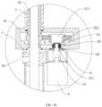
FIG. 9 illustrates a schematic diagram of one implementation of the first magnetic body and the second magnetic body radially disposed at the sealing hood of the second embodiment of the present invention; -
FIG. 10 illustrates a schematic diagram of another implementation of the first magnetic body and the second magnetic body radially disposed at the sealing hood of the second embodiment of the present invention; -
FIG. 11 illustrates a schematic diagram of one implementation of the first magnetic body and the second magnetic body axially disposed at the sealing hood of the second embodiment of the present invention. - Reference List: 1 mold assembly; 2 ring seat assembly; 3 cylinder body; 4 center rod; 5 driving motor; 6 sealing hood; 11 upper mold; 12 lower mold; 13 vulcanizing bladder; 14 upper chuck; 15 upper compression ring; 16 lower chuck; 17 lower steel ring; 21 gas circulating fan; 211 mating convex portion; 22 heating medium vent; 23 heater; 24 ring seat; 31 transmission box; 311 first shaft body; 32 rotating shaft; 321 annular flange; 322 accommodating concave portion; 51 second shaft body; 52 motor hood; 61 first magnetic body; 62 second magnetic body; 63 first seal; 64 second seal; 65 third seal; 66 fourth seal; 7 fixing component.
- The technical solutions of the present invention will be clearly and completely described below in conjunction with the accompanying drawings. Apparently, the described embodiments are some of the embodiments of the present invention, not all of them. Based on the embodiments of the present invention, all other embodiments obtained by those skilled in the art without making creative efforts fall into the protection scope of the present invention.
- In the description of the present invention, it should be noted that the orientation or positional relationship indicated by the terms "center", "upper", "lower", "left", "right", "vertical", "horizontal", "inside", "outside" and the like are based on the orientation or positional relationships shown in the accompanying drawings and are intended only to facilitate and simplify the description of the invention instead of indicating or implying that the device or element referred to must have a particular orientation, must be constructed and operated in a particular orientation, and therefore shall not be construed as limiting the invention. Furthermore, the terms "first", "second" and "third" are used for descriptive purposes only and shall not be construed as indicating or implying relative importance.
- In the description of the present invention, it is to be noted that, unless otherwise expressly specified and limited, the terms "mount", "connect", "couple" shall be understood in a broad sense. For example, it can be a fixed connection, a removable connection, or an integral connection; it can be a mechanical connection or an electrical connection; it can be a direct connection or an indirect connection through an intermediate medium, and it can be a connection within two elements. Those skilled in the art can understand the specific meanings of the above terms in the present invention according to specific situations.
- In addition, the technical features involved in the different embodiments of the invention described below can be combined with each other as long as they do not conflict to each other.
- Referring to
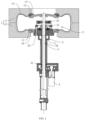
FIG. 1 , the present invention discloses a tire vulcanizing equipment comprising amold assembly 1, aring seat assembly 2 provided on the inside of themold assembly 1, a cylinder assembly supporting thering seat assembly 2, a driving member and a transmission assembly, thering seat assembly 2 being provided with agas circulating fan 21, the driving member driving thegas circulating fan 21 via the transmission assembly, the cylinder assembly comprising acylinder body 3 and atransmission box 31 provided on thecylinder body 3. - Referring to
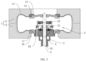
FIGS. 1 and2 , themold assembly 1 is a two-half mold, and may also be a two-half segment mold, an upper open segment mold or a lower open segment mold. Particularly, themold assembly 1 comprises anupper mold 11 and alower mold 12, and themold assembly 1 is also provided with avulcanizing bladder 13 inside it for molding the tire. Thering seat assembly 2 is located inside thevulcanizing bladder 13, and is provided with aheating medium vent 22. The heating medium is preferably nitrogen. Thering seat assembly 2 is provided with agas circulation fan 21 and aheater 23 which may be an electric heating tube, an induction heater, an infrared heater, a heat exchanger, etc. Theheater 23 heats the heating medium, and thegas circulating fan 21 drives the flow of the heating medium to flow, ensuring efficient heat transfer to the vulcanizingbladder 13 and uniform temperature inside thevulcanizing bladder 13, to facilitate tire molding. The gas circulating fan may be an impeller, axial fan, etc. - Referring to
FIGS. 1 and2 , the tire vulcanizing equipment further comprises acenter rod 4 threaded through thering seat assembly 2. Themold assembly 1 further comprises anupper chuck 14, anupper compression ring 15, alower chuck 16, and alower steel ring 17, wherein theupper chuck 14 and theupper compression ring 15 clamp the upper edge of thevulcanizing bladder 13, and thelower chuck 16 and thelower steel ring 17 clamp the lower edge of thevulcanizing bladder 13. Thelower chuck 16 is fixed to thering seat assembly 2, and more particularly, thering seat assembly 2 comprises aring seat 24, and thelower chuck 16 is threadedly connected to thering seat 24 and sealed with thering seat 24 by a seal, which may be a sealing ring. The top end of thecenter rod 4 is threaded to theupper chuck 14 and is fixedly connected to, such as bolted to theupper chuck 14, and the top end of thecenter rod 4 is sealed to theupper chuck 14 by a seal, which may be a seal ring. The sealing system is formed by the inside of themold assembly 1, thevulcanizing bladder 13, thering seat assembly 2, and the cylinder assembly, and the driving member is provided outside the sealing system to reduce the damage to the driving member by the high temperature and high pressure environment inside the sealing system. - Referring to
FIGS. 1 and2 , thering seat 24 and thecylinder body 3 can be provided as an integral structure, or they can also be bolted together and can also be sealed by a seal therebetween, the seal may be a sealing ring. - The
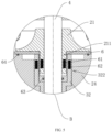
transmission box 31 and thecylinder body 3 can be provided as an integral structure, or of course they can also be bolted together and sealed by a seal therebetween, the seal may be a sealing ring. Referring toFIG. 1 and2 , the driving member is a drivingmotor 5, or it can be a combustion engine. Here the preferred solution is adriving motor 5. The drivingmotor 5 drives the rotatingshaft 32 to rotate, and in turn drives thegas circulating fan 21. The sealing system comprises asealing hood 6, the material of which can be Hastelloy, titanium alloy, etc. Thesealing hood 6 can function for sealing, magnetic conductivity and reducing eddy current of magnetic field. Thesealing hood 6 is provided on thering seat assembly 2 and is located between thegas circulating fan 21 and the rotatingshaft 32, thegas circulating fan 21 can rotate unimpeded relative to thesealing hood 6, and the rotatingshaft 32 drives thegas circulating fan 21 via magnetic members. Wherein afirst seal 63 is provided between thesealing hood 6 and the center rod, and asecond seal 64 is provided between theseal hood 6 and the ring seat, both thefirst seal 63 and thesecond seal 64 being sealing rings. - Referring to
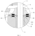
FIGS. 2 and3 , the magnetic members particularly comprise a firstmagnetic body 61 provided at the bottom of thegas circulating fan 21 and a secondmagnetic body 62 provided at the top of the rotatingshaft 32, wherein both the firstmagnetic body 61 and the secondmagnetic body 62 are magnets, particularly permanent magnets, and the firstmagnetic body 61 and the secondmagnetic body 62 have opposite magnetic poles. Further, the top end of therotating shaft 32 is provided with anannular flange 321 on which the secondmagnetic body 62 is provided, and the firstmagnetic body 61 and the secondmagnetic body 62 are positioned so that they correspond in the upper and lower positions, that is, the firstmagnetic body 61 and the secondmagnetic body 62 are disposed along the axial direction of therotating shaft 32. Wherein, the sealinghood 6 is located between the top end of therotating shaft 32 and thegas circulating fan 21, the sealinghood 6 is sleeved on thecenter rod 4, a sealing ring is provided between the sealinghood 6 and thecenter rod 4, and a sealing ring is provided between the sealinghood 6 and thering seat 24 for sealing. - Referring to
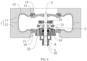
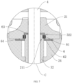
FIGS. 4 and5 , in an alternative implementation, the firstmagnetic body 61 and the secondmagnetic body 62 may also be positioned in a horizontal direction in correspondence, that is, the firstmagnetic body 61 and the secondmagnetic body 62 are arranged along the radial direction of therotating shaft 32. In particular, the top of therotating shaft 32 is provided with an accommodatingconcave portion 322, and the middle part of the bottom end of thegas circulating fan 21 is provided with a cooperatingconvex portion 211, where the shape of the sealinghood 6 is adapted to the gap between the accommodatingconcave portion 322 and the cooperatingconvex portion 211. During installation, the cooperatingconvex portion 211 extends into the accommodatingconcave portion 322, the firstmagnetic body 61 is arranged on the side wall of the cooperatingconvex portion 211, and the secondmagnetic body 62 is arranged on the side wall of the accommodatingconcave portion 322. - Referring to
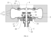
FIGS. 6 and7 , in another embodiment in which the first magnetic member and the second magnetic member are arranged in the radial direction of therotating shaft 32, the concave-convex fit of the top end of therotating shaft 32 and thegas circulating fan 21 changes, that is, the top end of therotating shaft 32 is provided with a cooperatingconvex portion 211 and the middle part of the bottom surface of thegas circulating fan 21 is provided with an accommodatingconcave portion 322, and the sealinghood 6 is shaped to fit with the gap between the cooperatingconvex portion 211 and the accommodatingconcave portion 322. During installation, the accommodatingconcave portion 322 extends into the cooperatingconvex portion 211, the firstmagnetic body 61 is arranged on the side wall of the accommodatingconcave portion 322, and the secondmagnetic body 62 is arranged on the side wall of the cooperatingconvex portion 211. - The implementation principle of the embodiment of the present invention is that at the beginning of tire vulcanizing, nitrogen is charged into the interior of the vulcanizing
bladder 13 through theheating medium vent 22 to provide internal pressure to the vulcanizingbladder 13, and theheater 23 generates heat to provide heat to the vulcanizingbladder 13. The drivingmotor 5 is operated such that the output shaft of the drivingmotor 5 drives the rotatingshaft 32 to rotate, and thegas circulating fan 21 works by means of the attraction of the firstmagnetic body 61 and the secondmagnetic body 62, to urge nitrogen circulation inside the vulcanizingbladder 13, thus improving the temperature uniformity. Among them, the drivingmotor 5 is isolated outside the sealing system by the sealinghood 6, such that the drivingmotor 5 works in a low temperature and pressure-free environment, reducing the damage to the drivingmotor 5, thus improving the service life of the drivingmotor 5. - The difference between the second embodiment and the first embodiment is that the first
magnetic body 61 and the secondmagnetic body 62 are provided in different positions. Referring toFIGS. 8 and9 , the transmission assembly comprises a first transmission member and a second transmission member, the first transmission member being afirst shaft body 311 and the second transmission member being asecond shaft body 51. The tire vulcanizing equipment further comprises atransmission box 31 provided on thecylinder body 3 with arotating shaft 32 threading through thetransmission box 31, the rotatingshaft 32 being a hollow shaft sleeved on thecenter rod 4 and provided in thecylinder body 3, the top end of therotating shaft 32 being connected to and driving thegas circulating fan 21 to rotate. Thefirst shaft body 311 is provided in thetransmission box 31. Thefirst shaft body 311 and therotating shaft 32 are engaged by means of gears, or may be driven by belts or sprockets. In this solution, they are preferably gear meshed. - The lower end of the
transmission box 31 and thecenter rod 4 may be sealed by a seal, or the lower end of thetransmission box 31 and a fixed component 7 outside of thecenter rod 4 are sealed by afourth seal 66. The fixed component 7 may be a cylinder block and the seal may be a sealing ring. - Referring to
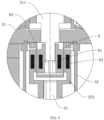
FIGS. 8 and9 , the drivingmotor 5 is fixed to thetransmission box 31, and the tire vulcanizing equipment further comprises amotor hood 52, one end of themotor hood 52 being connected to thetransmission box 31, and the other end of themotor hood 52 being connected to the drivingmotor 5, and the way of connection can be bolted or welded. The output shaft of the drivingmotor 5 is also connected to asecond shaft body 51, which may be connected by screws or couplings. The sealinghood 6 is provided on thetransmission box 31 to separate thefirst shaft body 311 and thesecond shaft body 51 apart, and both thesecond shaft body 51 and the sealinghood 6 are located inside themotor hood 52. The axis of thefirst shaft body 311 and thesecond shaft body 51 are the same. In this sulution, thefirst shaft body 311 and thesecond shaft body 51 are connected by magnetic components, so that thesecond shaft body 51 can drive thefirst shaft body 311 to rotate. - In particular, the first
magnetic body 61 is provided on thefirst shaft body 311, the secondmagnetic body 62 is provided on thesecond shaft body 51, wherein thefirst shaft body 311 projects outwardly, the end of thesecond shaft body 51 is recessed near thefirst shaft body 311 to form an accommodatingconcave portion 322, and the secondmagnetic body 62 is located on the side wall of the accommodatingconcave portion 322 to cover the projecting end of thefirst shaft body 311, such that the firstmagnetic body 61 is provided radially opposite to the secondmagnetic body 62 relative to thefirst shaft body 311, and with the attraction of the firstmagnetic body 61 to the secondmagnetic body 62, when the drivingmotor 5 drives thesecond shaft body 51 to rotate, thesecond shaft body 51 can follow the rotation, and in turn transmit the movement to therotating shaft 32 which drives thegas circulating fan 21 to rotate. There is also athird seal 65 provided between the sealinghood 6 and thetransmission box 31, and thethird seal 65 seals the gap between the sealinghood 6 and thetransmission box 31. Thethird seal 65 is preferably a sealing ring. - In another embodiment, referring to
FIGS. 8 and10 , the concave-convex fit between thefirst shaft body 311 and thesecond shaft body 51 is also interchangeable, that is, the end of thefirst shaft body 311 near thesecond shaft body 51 is provided with an accommodatingconcave portion 322, and the end of thesecond shaft body 51 near thefirst shaft body 311 is provided with a cooperatingconvex portion 211, and when thefirst shaft body 311 and thesecond shaft body 51 fit to each other, the cooperatingconvex portion 211 is located in the accommodatingconcave portion 322. Wherein, the firstmagnetic body 61 is provided on the side wall of the accommodatingconcave portion 322, the secondmagnetic body 62 is provided on the side wall of the cooperating convex portion211, and the firstmagnetic body 61 and the secondmagnetic body 62 are provided side by side in the radial direction of thefirst shaft body 311. - The implementation principle of this embodiment of the present invention is that at the beginning of tire vulcanizing, nitrogen is charged into the interior of the vulcanizing
bladder 13 through theheating medium vent 22 to provide internal pressure to the vulcanizingbladder 13, and theheater 23 generates heat to provide heat to the vulcanizingbladder 13. The drivingmotor 5 is operated such that the output shaft of the drivingmotor 5 drives the rotatingshaft 32 to rotate, and by means of the attraction of the firstmagnetic body 61 and the secondmagnetic body 62, thesecond shaft 51 drives thefirst shaft 311 to rotate, and thefirst shaft 311 drives the rotatingshaft 32 by means of the engagement of the gears to rotate therotating shaft 32, so that the rotatingshaft 32 rotates together, and therotating shaft 32 then drives thegas circulating fan 21 to work, urging the nitrogen circulation inside the vulcanizingbladder 13 and improving the temperature uniformity. Wherein, the drivingmotor 5 is isolated outside the sealing system by the sealinghood 6, which reduces the damage to the drivingmotor 5. - In another embodiment, the first
magnetic body 61 and the secondmagnetic body 62 are provided at different positions. Referring toFIG. 11 , particularly, thefirst shaft body 311 and thesecond shaft body 51 are provided coaxially, the sealinghood 6 separates thefirst shaft body 311 and thesecond shaft body 51 apart, the firstmagnetic body 61 is provided at the end of thefirst shaft body 311 near thesecond shaft body 51, and the secondmagnetic body 62 is provided at the end of thesecond shaft body 51 near thefirst shaft body 311. At this time, thefirst axis body 311 and thesecond axis body 51 are axially facing each other. When thesecond shaft body 51 rotates, thefirst shaft body 311 is rotated by means of magnetic attraction between the firstmagnetic body 61 and the secondmagnetic body 62.
Claims (7)
- A tire vulcanizing equipment comprising:a mold assembly (1) provided with a vulcanizing bladder (13) inside of the mold assembly for tire molding;a ring seat assembly (2) provided inside the mold assembly (1), the ring seat assembly (2) being provided with a gas circulating fan (21), the ring seat assembly (2) is provided with a heating medium vent (22);a cylinder assembly provided on the ring seat assembly (2), the cylinder assembly having a rotating shaft (32) provided within the cylinder assembly, the rotating shaft (32) being adapted to drive the gas circulating fan (21) to rotate;a driving member adapted to drive the rotating shaft (32) to rotate;a sealing hood (6) adapted to seal off gas inside the mold assembly (1);wherein the sealing hood (6) is provided on the ring seat assembly (2) and is located between the gas circulating fan (21) and the rotating shaft (32), the rotating shaft (32) driving the gas circulating fan (21) to rotate by means of magnetic members;the magnetic members comprising a first magnetic body (61) provided on the gas circulating fan (21) and a second magnetic body provided on the rotating shaft (32), the first magnetic body (61) and the second magnetic body being provided correspondingly;the tire vulcanizing equipment further comprising a center rod (4) threaded through the ring seat assembly (2), the ring seat assembly (2) comprising a ring seat (24) and a heater (23); characterised in that eitherthe sealing hood (6) is located between the top end of the rotating shaft (32) and the gas circulating fan (21), the sealing hood (6) is sleeved on the center rod (4); a first seal (63) is provided between the sealing hood (6) and the center rod (4), and a second seal (64) is provided between the sealing hood (6) and the ring seat (24);a sealing system is formed by the inside of the mold assembly (1), the vulcanizing bladder (13), the ring seat assembly (2), and the cylinder assembly, and the driving member is provided outside the sealing system;or in thatthe sealing hood (6) is provided on the cylinder assembly and is located between the rotating shaft (32) and the driving member, the driving member driving the rotating shaft (32) to rotate by means of magnetic members;the cylinder assembly comprises a cylinder body (3) and a transmission box (31) provided on the cylinder body (3), the sealing hood (6) being provided on the transmission box (31) and sealing the inner and outer space of the transmission box (31), wherein a first transmission member driving the rotating shaft (32) to rotate is provided inside the transmission box (31), and a second transmission member is provided outside the transmission box (31), the driving member being connected to the second transmission member, the first transmission member and the second transmission member being located on either side of the sealing hood (6) respectively; and the magnetic members comprise a first magnetic body (61) provided on the first transmission member and a second magnetic body provided on the second transmission member, the first magnetic body (61) and the second magnetic body being provided correspondingly;the first transmission member comprises a first shaft body (311) connected to the rotating shaft (32) through a gear mechanism, and the second transmission member comprises a second shaft body (51) connected to an output shaft of the driving member;the sealing hood (6) is provided on the transmission box (31) to separate the first shaft body (311) and the second shaft body (51) apart; a third seal (65) is provided between the sealing hood (6) and the cylinder assembly.
- The tire vulcanizing equipment according to claim 1, characterized in that the end of the rotating shaft (32) is provided with an annular flange (321), wherein the first magnetic body (61) is provided on the bottom wall of the gas circulating fan (21), the second magnetic body is provided on the annular flange (321), and the first magnetic body (61) and second magnetic body are arranged along the axial direction of the rotating shaft (32).
- The tire vulcanizing equipment according to claim 1, characterized in that an end of the rotating shaft (32) is provided with an accommodating concave portion (322) and a middle part of the gas circulating fan (21) is provided with a cooperating convex portion (211), the shape of the sealing hood (6) being adapted to the accommodating concave portion (322) and the cooperating convex portion (211), the cooperating convex portion (211) extending into the accommodating concave portion (322), wherein the first magnetic body (61) is provided on the side wall of the cooperating convex portion (211) and the second magnetic body is provided on the side wall of the accommodating concave portion (322), the first magnetic body (61) and the second magnetic body being arranged along the radial direction of the rotating shaft (32).
- The tire vulcanizing equipment according to claim 1, characterized in that an end of the rotating shaft (32) is provided with a cooperating convex portion (211) and a middle part of the gas circulating fan (21) is provided with an accommodating concave portion (322), the shape of the sealing hood (6) being adapted to the cooperating convex portion (211) and the accommodating concave portion (322), the accommodating concave portion (322) extending into the cooperating convex portion (211), wherein the first magnetic body (61) is provided on the side wall of the accommodating concave portion (322) and the second magnetic body is provided on the side wall of the cooperating convex portion (211), the first magnetic body (61) and the second magnetic body being arranged along the radial direction of the rotating shaft (32).
- The tire vulcanizing equipment according to claim 1, characterized in that the first magnetic body (61) is provided on the end face of the first shaft body (311) and the second magnetic body is provided on the end face of the second shaft body (51), both of which are arranged along the axial direction of the first shaft body (311).
- The tire vulcanizing equipment according to claim 1, characterized in that the sealing hood (6) projects toward the outside of the transmission box (31), the first shaft body (311) extends into the sealing hood (6), the second shaft body (51) is provided with an accommodating concave portion (322) on its end face, the sealing hood (6) extends into the accommodating concave portion (322), the first magnetic body (61) is provided on the side wall of the first shaft body (311), the second magnetic body is provided on the side wall of the accommodating concave portion (322), and the first magnetic body (61) and the second magnetic body are arranged along the radial direction of the first shaft body (311).
- The tire vulcanizing equipment according to claim 5 or 6, characterized in that the driving member is a driving motor (5), and the tire vulcanizing equipment further comprises a motor hood (52), one end of the motor hood (52) being connected to the transmission box (31), the other end of the motor hood (52) being connected to the driving motor (5), the sealing hood (6) and second shaft body (51) both being located within the motor hood (52).
Priority Applications (2)
| Application Number | Priority Date | Filing Date | Title |
|---|---|---|---|
| EP25155219.6A EP4523899A3 (en) | 2021-12-13 | 2022-09-23 | Tire vulcanizing equipment |
| HRP20250496TT HRP20250496T1 (en) | 2021-12-13 | 2022-09-23 | EQUIPMENT FOR TYRE VULCANIZATION |
Applications Claiming Priority (2)
| Application Number | Priority Date | Filing Date | Title |
|---|---|---|---|
| CN202111521976.XA CN114179409B (en) | 2021-12-13 | 2021-12-13 | A tire vulcanization equipment |
| PCT/CN2022/120732 WO2023103532A1 (en) | 2021-12-13 | 2022-09-23 | Tire vulcanizing equipment |
Related Child Applications (2)
| Application Number | Title | Priority Date | Filing Date |
|---|---|---|---|
| EP25155219.6A Division EP4523899A3 (en) | 2021-12-13 | 2022-09-23 | Tire vulcanizing equipment |
| EP25155219.6A Division-Into EP4523899A3 (en) | 2021-12-13 | 2022-09-23 | Tire vulcanizing equipment |
Publications (3)
| Publication Number | Publication Date |
|---|---|
| EP4316789A1 EP4316789A1 (en) | 2024-02-07 |
| EP4316789A4 EP4316789A4 (en) | 2024-06-19 |
| EP4316789B1 true EP4316789B1 (en) | 2025-03-12 |
Family
ID=80604814
Family Applications (2)
| Application Number | Title | Priority Date | Filing Date |
|---|---|---|---|
| EP22902957.4A Active EP4316789B1 (en) | 2021-12-13 | 2022-09-23 | Tire vulcanizing equipment |
| EP25155219.6A Pending EP4523899A3 (en) | 2021-12-13 | 2022-09-23 | Tire vulcanizing equipment |
Family Applications After (1)
| Application Number | Title | Priority Date | Filing Date |
|---|---|---|---|
| EP25155219.6A Pending EP4523899A3 (en) | 2021-12-13 | 2022-09-23 | Tire vulcanizing equipment |
Country Status (9)
| Country | Link |
|---|---|
| US (1) | US12151447B2 (en) |
| EP (2) | EP4316789B1 (en) |
| JP (1) | JP7513851B2 (en) |
| KR (1) | KR102796114B1 (en) |
| CN (1) | CN114179409B (en) |
| DE (1) | DE202022002843U1 (en) |
| HR (1) | HRP20250496T1 (en) |
| HU (1) | HUE071749T2 (en) |
| WO (1) | WO2023103532A1 (en) |
Families Citing this family (9)
| Publication number | Priority date | Publication date | Assignee | Title |
|---|---|---|---|---|
| CN114179410B (en) | 2021-12-13 | 2023-09-29 | 山东豪迈机械科技股份有限公司 | A vulcanization equipment |
| CN114179409B (en) | 2021-12-13 | 2023-09-29 | 山东豪迈机械科技股份有限公司 | A tire vulcanization equipment |
| CN116604853B (en) * | 2023-07-20 | 2023-09-29 | 山东豪迈机械科技股份有限公司 | Heating gas circulation mould subassembly and curing facilities |
| CN116604862B (en) * | 2023-07-20 | 2023-10-10 | 山东豪迈数控机床有限公司 | Tire vulcanizing equipment |
| CN116619799B (en) * | 2023-07-20 | 2023-10-03 | 山东豪迈数控机床有限公司 | Tire vulcanizing device |
| CN116604864B (en) * | 2023-07-20 | 2023-10-10 | 山东豪迈机械科技股份有限公司 | Gas circulation device and tire vulcanization equipment including the gas circulation device |
| CN116604863B (en) * | 2023-07-20 | 2023-12-01 | 山东豪迈机械科技股份有限公司 | Vulcanizing device |
| CN119408210A (en) * | 2025-01-06 | 2025-02-11 | 山东豪迈数控机床有限公司 | Electric heating vulcanization equipment |
| CN120396409B (en) * | 2025-07-01 | 2025-11-07 | 山东豪迈机械科技股份有限公司 | A tire vulcanizing equipment |
Citations (5)
| Publication number | Priority date | Publication date | Assignee | Title |
|---|---|---|---|---|
| JP2006022644A (en) * | 2002-03-07 | 2006-01-26 | Ichimaru Giken:Kk | Liquid feeding device and tire vulcanizing device using the same |
| WO2010109603A1 (en) * | 2009-03-25 | 2010-09-30 | 平田機工株式会社 | Tire vulcanizer |
| CN108162449A (en) | 2018-01-30 | 2018-06-15 | 青岛双星橡塑机械有限公司 | Energy-saving tyre vulcanizer |
| CN108297322A (en) | 2018-02-05 | 2018-07-20 | 青岛双星橡塑机械有限公司 | Energy-saving tyre vulcanizer |
| CN110181841A (en) | 2019-06-24 | 2019-08-30 | 张掖市麒祥轮胎技术开发有限公司 | A kind of central authority of tire short vulcanization machine |
Family Cites Families (15)
| Publication number | Priority date | Publication date | Assignee | Title |
|---|---|---|---|---|
| JPS59115827A (en) * | 1982-12-23 | 1984-07-04 | Bridgestone Corp | Vulcanizer for tire |
| DE3818890A1 (en) * | 1988-06-03 | 1989-12-07 | Ekato Ind Anlagen Verwalt | ARRANGEMENT FOR SECURELY SEALING THE BEARING OF A ROTATING SHAFT WITH AN RELATED DRIVE ELEMENT |
| JP3828726B2 (en) * | 2000-07-31 | 2006-10-04 | 株式会社神戸製鋼所 | Vulcanizer |
| EP2710719B2 (en) * | 2011-05-13 | 2020-04-29 | Carrier Corporation | Magnetic drive coupling apparatus |
| JP5400182B2 (en) * | 2012-01-11 | 2014-01-29 | 株式会社神戸製鋼所 | Vulcanizer |
| FR2990150B1 (en) * | 2012-05-02 | 2015-01-09 | Michelin & Cie | ENCLOSURE FOR VULCANIZING THE INNER PART OF A TIRE CONTAINING A FAN |
| CN104742284A (en) | 2013-12-26 | 2015-07-01 | 软控股份有限公司 | Tyre vulcanizer central mechanism and tyre vulcanizer |
| FR3028444B1 (en) * | 2014-11-19 | 2017-10-06 | Michelin & Cie | DEVICE AND METHOD FOR VULCANIZING TIRES |
| EP3192647B1 (en) * | 2016-01-14 | 2019-03-06 | Compagnie Générale des Etablissements Michelin | Operation of a tire vulcanization system |
| FR3048913B1 (en) | 2016-03-21 | 2018-03-09 | Compagnie Generale Des Etablissements Michelin | MAXIMIZE THE LIFETIME OF GUIDING MEANS IN TIRE VULCANIZATION SYSTEMS WITHOUT AFFECTING THERMAL STABILITY |
| CN209061033U (en) * | 2018-03-05 | 2019-07-05 | 四川省德名斯科技有限公司 | A kind of spiral tone pitch poking bar |
| CN108481768A (en) * | 2018-05-23 | 2018-09-04 | 青岛万龙智控科技有限公司 | Machine and mold integrated vulcanizing machine and its method |
| CN109795060B (en) * | 2019-04-01 | 2021-06-08 | 淮阴工学院 | A kind of vulcanization device and method for vibration curing rubber tire |
| CN112297483B (en) * | 2020-10-09 | 2021-09-14 | 江苏诚泰车辆有限公司 | Avoid waste gas pollution's vulcanizer for tire processing |
| CN114179409B (en) | 2021-12-13 | 2023-09-29 | 山东豪迈机械科技股份有限公司 | A tire vulcanization equipment |
-
2021
- 2021-12-13 CN CN202111521976.XA patent/CN114179409B/en active Active
-
2022
- 2022-09-23 HU HUE22902957A patent/HUE071749T2/en unknown
- 2022-09-23 US US18/558,813 patent/US12151447B2/en active Active
- 2022-09-23 EP EP22902957.4A patent/EP4316789B1/en active Active
- 2022-09-23 WO PCT/CN2022/120732 patent/WO2023103532A1/en not_active Ceased
- 2022-09-23 KR KR1020237038006A patent/KR102796114B1/en active Active
- 2022-09-23 EP EP25155219.6A patent/EP4523899A3/en active Pending
- 2022-09-23 DE DE202022002843.1U patent/DE202022002843U1/en active Active
- 2022-09-23 HR HRP20250496TT patent/HRP20250496T1/en unknown
- 2022-09-23 JP JP2023558221A patent/JP7513851B2/en active Active
Patent Citations (5)
| Publication number | Priority date | Publication date | Assignee | Title |
|---|---|---|---|---|
| JP2006022644A (en) * | 2002-03-07 | 2006-01-26 | Ichimaru Giken:Kk | Liquid feeding device and tire vulcanizing device using the same |
| WO2010109603A1 (en) * | 2009-03-25 | 2010-09-30 | 平田機工株式会社 | Tire vulcanizer |
| CN108162449A (en) | 2018-01-30 | 2018-06-15 | 青岛双星橡塑机械有限公司 | Energy-saving tyre vulcanizer |
| CN108297322A (en) | 2018-02-05 | 2018-07-20 | 青岛双星橡塑机械有限公司 | Energy-saving tyre vulcanizer |
| CN110181841A (en) | 2019-06-24 | 2019-08-30 | 张掖市麒祥轮胎技术开发有限公司 | A kind of central authority of tire short vulcanization machine |
Also Published As
| Publication number | Publication date |
|---|---|
| CN114179409A (en) | 2022-03-15 |
| US20240239070A1 (en) | 2024-07-18 |
| DE202022002843U1 (en) | 2023-10-04 |
| JP2024518872A (en) | 2024-05-08 |
| EP4316789A1 (en) | 2024-02-07 |
| US12151447B2 (en) | 2024-11-26 |
| KR102796114B1 (en) | 2025-04-14 |
| HRP20250496T1 (en) | 2025-06-20 |
| WO2023103532A1 (en) | 2023-06-15 |
| JP7513851B2 (en) | 2024-07-09 |
| KR20230158129A (en) | 2023-11-17 |
| EP4523899A2 (en) | 2025-03-19 |
| HUE071749T2 (en) | 2025-09-28 |
| EP4523899A3 (en) | 2025-06-25 |
| EP4316789A4 (en) | 2024-06-19 |
| CN114179409B (en) | 2023-09-29 |
Similar Documents
| Publication | Publication Date | Title |
|---|---|---|
| EP4316789B1 (en) | Tire vulcanizing equipment | |
| CN216400630U (en) | A tire vulcanization equipment | |
| US12179448B2 (en) | Vulcanizing equipment | |
| EP3433090B1 (en) | Maximizing the duration of guidance means in tire vulcanization systems without disturbing thermal stability | |
| CN110224552B (en) | Dual-cooling motor structure | |
| CN116604854B (en) | A vulcanization equipment | |
| CN114301223B (en) | Rotor heat dissipation mechanism of flywheel energy storage system | |
| WO2024067788A1 (en) | Tire curing press | |
| CN204068554U (en) | A kind of motor with pressure vessel coupling | |
| CN223785888U (en) | Tire vulcanizing machine motor cooling device | |
| CN116613922A (en) | Rotary drives and tire curing presses | |
| CN215885132U (en) | Combined permanent magnetic disk type electric roller | |
| CN207195656U (en) | Rubber antelabium friction pair type stern shaft seal gland | |
| CN223784336U (en) | Tire vulcanizing machine motor testing device | |
| CN214101161U (en) | Magnetic coupling assembly, fixing piece and transmission mechanism | |
| CN119427802B (en) | Tire vulcanizer | |
| CN110535281A (en) | A liquid-cooled motor housing and manufacturing method thereof | |
| CN121067051A (en) | A magnetically driven high-temperature and high-pressure sealed container internal flow field equalization device | |
| CN218217149U (en) | Conveying driving device used in vacuum environment | |
| CN204794571U (en) | High -effect energy -saving motor | |
| CN222875378U (en) | Tire vulcanizer | |
| CN215419937U (en) | An electric wheel hub motor | |
| CN221354022U (en) | Rotor support assembly | |
| CN116604864B (en) | Gas circulation device and tire vulcanization equipment including the gas circulation device | |
| CN104682624A (en) | Motor cooling water jacket |
Legal Events
| Date | Code | Title | Description |
|---|---|---|---|
| REG | Reference to a national code |
Ref country code: HR Ref legal event code: TUEP Ref document number: P20250496T Country of ref document: HR |
|
| STAA | Information on the status of an ep patent application or granted ep patent |
Free format text: STATUS: THE INTERNATIONAL PUBLICATION HAS BEEN MADE |
|
| PUAI | Public reference made under article 153(3) epc to a published international application that has entered the european phase |
Free format text: ORIGINAL CODE: 0009012 |
|
| STAA | Information on the status of an ep patent application or granted ep patent |
Free format text: STATUS: REQUEST FOR EXAMINATION WAS MADE |
|
| 17P | Request for examination filed |
Effective date: 20231027 |
|
| AK | Designated contracting states |
Kind code of ref document: A1 Designated state(s): AL AT BE BG CH CY CZ DE DK EE ES FI FR GB GR HR HU IE IS IT LI LT LU LV MC MK MT NL NO PL PT RO RS SE SI SK SM TR |
|
| TPAC | Observations filed by third parties |
Free format text: ORIGINAL CODE: EPIDOSNTIPA |
|
| A4 | Supplementary search report drawn up and despatched |
Effective date: 20240522 |
|
| RIC1 | Information provided on ipc code assigned before grant |
Ipc: B29D 30/06 20060101AFI20240515BHEP |
|
| GRAP | Despatch of communication of intention to grant a patent |
Free format text: ORIGINAL CODE: EPIDOSNIGR1 |
|
| STAA | Information on the status of an ep patent application or granted ep patent |
Free format text: STATUS: GRANT OF PATENT IS INTENDED |
|
| DAV | Request for validation of the european patent (deleted) | ||
| DAX | Request for extension of the european patent (deleted) | ||
| INTG | Intention to grant announced |
Effective date: 20241004 |
|
| GRAS | Grant fee paid |
Free format text: ORIGINAL CODE: EPIDOSNIGR3 |
|
| GRAA | (expected) grant |
Free format text: ORIGINAL CODE: 0009210 |
|
| STAA | Information on the status of an ep patent application or granted ep patent |
Free format text: STATUS: THE PATENT HAS BEEN GRANTED |
|
| AK | Designated contracting states |
Kind code of ref document: B1 Designated state(s): AL AT BE BG CH CY CZ DE DK EE ES FI FR GB GR HR HU IE IS IT LI LT LU LV MC MK MT NL NO PL PT RO RS SE SI SK SM TR |
|
| REG | Reference to a national code |
Ref country code: GB Ref legal event code: FG4D |
|
| REG | Reference to a national code |
Ref country code: CH Ref legal event code: EP |
|
| P01 | Opt-out of the competence of the unified patent court (upc) registered |
Free format text: CASE NUMBER: APP_7168/2025 Effective date: 20250212 |
|
| REG | Reference to a national code |
Ref country code: DE Ref legal event code: R096 Ref document number: 602022011818 Country of ref document: DE |
|
| REG | Reference to a national code |
Ref country code: IE Ref legal event code: FG4D |
|
| REG | Reference to a national code |
Ref country code: NL Ref legal event code: FP |
|
| REG | Reference to a national code |
Ref country code: HR Ref legal event code: T1PR Ref document number: P20250496 Country of ref document: HR |
|
| PG25 | Lapsed in a contracting state [announced via postgrant information from national office to epo] |
Ref country code: RS Free format text: LAPSE BECAUSE OF FAILURE TO SUBMIT A TRANSLATION OF THE DESCRIPTION OR TO PAY THE FEE WITHIN THE PRESCRIBED TIME-LIMIT Effective date: 20250612 |
|
| PG25 | Lapsed in a contracting state [announced via postgrant information from national office to epo] |
Ref country code: FI Free format text: LAPSE BECAUSE OF FAILURE TO SUBMIT A TRANSLATION OF THE DESCRIPTION OR TO PAY THE FEE WITHIN THE PRESCRIBED TIME-LIMIT Effective date: 20250312 |
|
| PG25 | Lapsed in a contracting state [announced via postgrant information from national office to epo] |
Ref country code: ES Free format text: LAPSE BECAUSE OF FAILURE TO SUBMIT A TRANSLATION OF THE DESCRIPTION OR TO PAY THE FEE WITHIN THE PRESCRIBED TIME-LIMIT Effective date: 20250312 |
|
| REG | Reference to a national code |
Ref country code: LT Ref legal event code: MG9D |
|
| PG25 | Lapsed in a contracting state [announced via postgrant information from national office to epo] |
Ref country code: NO Free format text: LAPSE BECAUSE OF FAILURE TO SUBMIT A TRANSLATION OF THE DESCRIPTION OR TO PAY THE FEE WITHIN THE PRESCRIBED TIME-LIMIT Effective date: 20250612 |
|
| PG25 | Lapsed in a contracting state [announced via postgrant information from national office to epo] |
Ref country code: LV Free format text: LAPSE BECAUSE OF FAILURE TO SUBMIT A TRANSLATION OF THE DESCRIPTION OR TO PAY THE FEE WITHIN THE PRESCRIBED TIME-LIMIT Effective date: 20250312 |
|
| PG25 | Lapsed in a contracting state [announced via postgrant information from national office to epo] |
Ref country code: GR Free format text: LAPSE BECAUSE OF FAILURE TO SUBMIT A TRANSLATION OF THE DESCRIPTION OR TO PAY THE FEE WITHIN THE PRESCRIBED TIME-LIMIT Effective date: 20250613 Ref country code: BG Free format text: LAPSE BECAUSE OF FAILURE TO SUBMIT A TRANSLATION OF THE DESCRIPTION OR TO PAY THE FEE WITHIN THE PRESCRIBED TIME-LIMIT Effective date: 20250312 |
|
| REG | Reference to a national code |
Ref country code: AT Ref legal event code: MK05 Ref document number: 1774688 Country of ref document: AT Kind code of ref document: T Effective date: 20250312 |
|
| PG25 | Lapsed in a contracting state [announced via postgrant information from national office to epo] |
Ref country code: SE Free format text: LAPSE BECAUSE OF FAILURE TO SUBMIT A TRANSLATION OF THE DESCRIPTION OR TO PAY THE FEE WITHIN THE PRESCRIBED TIME-LIMIT Effective date: 20250312 |
|
| PGFP | Annual fee paid to national office [announced via postgrant information from national office to epo] |
Ref country code: NL Payment date: 20250814 Year of fee payment: 4 |
|
| REG | Reference to a national code |
Ref country code: HR Ref legal event code: ODRP Ref document number: P20250496 Country of ref document: HR Payment date: 20250806 Year of fee payment: 4 |
|
| REG | Reference to a national code |
Ref country code: HU Ref legal event code: AG4A Ref document number: E071749 Country of ref document: HU |
|
| PG25 | Lapsed in a contracting state [announced via postgrant information from national office to epo] |
Ref country code: SM Free format text: LAPSE BECAUSE OF FAILURE TO SUBMIT A TRANSLATION OF THE DESCRIPTION OR TO PAY THE FEE WITHIN THE PRESCRIBED TIME-LIMIT Effective date: 20250312 |
|
| PG25 | Lapsed in a contracting state [announced via postgrant information from national office to epo] |
Ref country code: PT Free format text: LAPSE BECAUSE OF FAILURE TO SUBMIT A TRANSLATION OF THE DESCRIPTION OR TO PAY THE FEE WITHIN THE PRESCRIBED TIME-LIMIT Effective date: 20250714 |
|
| PGFP | Annual fee paid to national office [announced via postgrant information from national office to epo] |
Ref country code: DE Payment date: 20250730 Year of fee payment: 4 |
|
| PG25 | Lapsed in a contracting state [announced via postgrant information from national office to epo] |
Ref country code: PL Free format text: LAPSE BECAUSE OF FAILURE TO SUBMIT A TRANSLATION OF THE DESCRIPTION OR TO PAY THE FEE WITHIN THE PRESCRIBED TIME-LIMIT Effective date: 20250312 |
|
| PGFP | Annual fee paid to national office [announced via postgrant information from national office to epo] |
Ref country code: TR Payment date: 20250917 Year of fee payment: 4 Ref country code: LU Payment date: 20250912 Year of fee payment: 4 |
|
| PGFP | Annual fee paid to national office [announced via postgrant information from national office to epo] |
Ref country code: HU Payment date: 20250828 Year of fee payment: 4 |
|
| PGFP | Annual fee paid to national office [announced via postgrant information from national office to epo] |
Ref country code: HR Payment date: 20250806 Year of fee payment: 4 |
|
| PG25 | Lapsed in a contracting state [announced via postgrant information from national office to epo] |
Ref country code: AT Free format text: LAPSE BECAUSE OF FAILURE TO SUBMIT A TRANSLATION OF THE DESCRIPTION OR TO PAY THE FEE WITHIN THE PRESCRIBED TIME-LIMIT Effective date: 20250312 |
|
| PGFP | Annual fee paid to national office [announced via postgrant information from national office to epo] |
Ref country code: FR Payment date: 20250808 Year of fee payment: 4 |
|
| PG25 | Lapsed in a contracting state [announced via postgrant information from national office to epo] |
Ref country code: CZ Free format text: LAPSE BECAUSE OF FAILURE TO SUBMIT A TRANSLATION OF THE DESCRIPTION OR TO PAY THE FEE WITHIN THE PRESCRIBED TIME-LIMIT Effective date: 20250312 Ref country code: EE Free format text: LAPSE BECAUSE OF FAILURE TO SUBMIT A TRANSLATION OF THE DESCRIPTION OR TO PAY THE FEE WITHIN THE PRESCRIBED TIME-LIMIT Effective date: 20250312 |
|
| PGFP | Annual fee paid to national office [announced via postgrant information from national office to epo] |
Ref country code: RO Payment date: 20250828 Year of fee payment: 4 |
|
| PG25 | Lapsed in a contracting state [announced via postgrant information from national office to epo] |
Ref country code: SK Free format text: LAPSE BECAUSE OF FAILURE TO SUBMIT A TRANSLATION OF THE DESCRIPTION OR TO PAY THE FEE WITHIN THE PRESCRIBED TIME-LIMIT Effective date: 20250312 |
|
| PG25 | Lapsed in a contracting state [announced via postgrant information from national office to epo] |
Ref country code: IS Free format text: LAPSE BECAUSE OF FAILURE TO SUBMIT A TRANSLATION OF THE DESCRIPTION OR TO PAY THE FEE WITHIN THE PRESCRIBED TIME-LIMIT Effective date: 20250712 |
|
| REG | Reference to a national code |
Ref country code: DE Ref legal event code: R026 Ref document number: 602022011818 Country of ref document: DE |
|
| PLBI | Opposition filed |
Free format text: ORIGINAL CODE: 0009260 |