EP4316776A1 - Apparatus and method for pouch molding - Google Patents
Apparatus and method for pouch molding Download PDFInfo
- Publication number
- EP4316776A1 EP4316776A1 EP22911728.8A EP22911728A EP4316776A1 EP 4316776 A1 EP4316776 A1 EP 4316776A1 EP 22911728 A EP22911728 A EP 22911728A EP 4316776 A1 EP4316776 A1 EP 4316776A1
- Authority
- EP
- European Patent Office
- Prior art keywords
- pouch
- punch
- die groove
- die
- body part
- Prior art date
- Legal status (The legal status is an assumption and is not a legal conclusion. Google has not performed a legal analysis and makes no representation as to the accuracy of the status listed.)
- Granted
Links
Images


Classifications
-
- B—PERFORMING OPERATIONS; TRANSPORTING
- B29—WORKING OF PLASTICS; WORKING OF SUBSTANCES IN A PLASTIC STATE IN GENERAL
- B29C—SHAPING OR JOINING OF PLASTICS; SHAPING OF MATERIAL IN A PLASTIC STATE, NOT OTHERWISE PROVIDED FOR; AFTER-TREATMENT OF THE SHAPED PRODUCTS, e.g. REPAIRING
- B29C51/00—Shaping by thermoforming, i.e. shaping sheets or sheet like preforms after heating, e.g. shaping sheets in matched moulds or by deep-drawing; Apparatus therefor
- B29C51/08—Deep drawing or matched-mould forming, i.e. using mechanical means only
- B29C51/082—Deep drawing or matched-mould forming, i.e. using mechanical means only by shaping between complementary mould parts
-
- B—PERFORMING OPERATIONS; TRANSPORTING
- B29—WORKING OF PLASTICS; WORKING OF SUBSTANCES IN A PLASTIC STATE IN GENERAL
- B29C—SHAPING OR JOINING OF PLASTICS; SHAPING OF MATERIAL IN A PLASTIC STATE, NOT OTHERWISE PROVIDED FOR; AFTER-TREATMENT OF THE SHAPED PRODUCTS, e.g. REPAIRING
- B29C43/00—Compression moulding, i.e. applying external pressure to flow the moulding material; Apparatus therefor
- B29C43/32—Component parts, details or accessories; Auxiliary operations
- B29C43/36—Moulds for making articles of definite length, i.e. discrete articles
-
- B—PERFORMING OPERATIONS; TRANSPORTING
- B21—MECHANICAL METAL-WORKING WITHOUT ESSENTIALLY REMOVING MATERIAL; PUNCHING METAL
- B21D—WORKING OR PROCESSING OF SHEET METAL OR METAL TUBES, RODS OR PROFILES WITHOUT ESSENTIALLY REMOVING MATERIAL; PUNCHING METAL
- B21D22/00—Shaping without cutting, by stamping, spinning, or deep-drawing
- B21D22/20—Deep-drawing
- B21D22/208—Deep-drawing by heating the blank or deep-drawing associated with heat treatment
-
- B—PERFORMING OPERATIONS; TRANSPORTING
- B21—MECHANICAL METAL-WORKING WITHOUT ESSENTIALLY REMOVING MATERIAL; PUNCHING METAL
- B21D—WORKING OR PROCESSING OF SHEET METAL OR METAL TUBES, RODS OR PROFILES WITHOUT ESSENTIALLY REMOVING MATERIAL; PUNCHING METAL
- B21D53/00—Making other particular articles
-
- B—PERFORMING OPERATIONS; TRANSPORTING
- B29—WORKING OF PLASTICS; WORKING OF SUBSTANCES IN A PLASTIC STATE IN GENERAL
- B29C—SHAPING OR JOINING OF PLASTICS; SHAPING OF MATERIAL IN A PLASTIC STATE, NOT OTHERWISE PROVIDED FOR; AFTER-TREATMENT OF THE SHAPED PRODUCTS, e.g. REPAIRING
- B29C43/00—Compression moulding, i.e. applying external pressure to flow the moulding material; Apparatus therefor
- B29C43/32—Component parts, details or accessories; Auxiliary operations
- B29C43/36—Moulds for making articles of definite length, i.e. discrete articles
- B29C43/361—Moulds for making articles of definite length, i.e. discrete articles with pressing members independently movable of the parts for opening or closing the mould, e.g. movable pistons
-
- B—PERFORMING OPERATIONS; TRANSPORTING
- B29—WORKING OF PLASTICS; WORKING OF SUBSTANCES IN A PLASTIC STATE IN GENERAL
- B29C—SHAPING OR JOINING OF PLASTICS; SHAPING OF MATERIAL IN A PLASTIC STATE, NOT OTHERWISE PROVIDED FOR; AFTER-TREATMENT OF THE SHAPED PRODUCTS, e.g. REPAIRING
- B29C43/00—Compression moulding, i.e. applying external pressure to flow the moulding material; Apparatus therefor
- B29C43/32—Component parts, details or accessories; Auxiliary operations
- B29C43/52—Heating or cooling
-
- H—ELECTRICITY
- H01—ELECTRIC ELEMENTS
- H01M—PROCESSES OR MEANS, e.g. BATTERIES, FOR THE DIRECT CONVERSION OF CHEMICAL ENERGY INTO ELECTRICAL ENERGY
- H01M50/00—Constructional details or processes of manufacture of the non-active parts of electrochemical cells other than fuel cells, e.g. hybrid cells
- H01M50/10—Primary casings; Jackets or wrappings
- H01M50/102—Primary casings; Jackets or wrappings characterised by their shape or physical structure
- H01M50/105—Pouches or flexible bags
-
- B—PERFORMING OPERATIONS; TRANSPORTING
- B29—WORKING OF PLASTICS; WORKING OF SUBSTANCES IN A PLASTIC STATE IN GENERAL
- B29C—SHAPING OR JOINING OF PLASTICS; SHAPING OF MATERIAL IN A PLASTIC STATE, NOT OTHERWISE PROVIDED FOR; AFTER-TREATMENT OF THE SHAPED PRODUCTS, e.g. REPAIRING
- B29C43/00—Compression moulding, i.e. applying external pressure to flow the moulding material; Apparatus therefor
- B29C43/32—Component parts, details or accessories; Auxiliary operations
- B29C2043/3272—Component parts, details or accessories; Auxiliary operations driving means
- B29C2043/3283—Component parts, details or accessories; Auxiliary operations driving means for moving moulds or mould parts
-
- B—PERFORMING OPERATIONS; TRANSPORTING
- B29—WORKING OF PLASTICS; WORKING OF SUBSTANCES IN A PLASTIC STATE IN GENERAL
- B29C—SHAPING OR JOINING OF PLASTICS; SHAPING OF MATERIAL IN A PLASTIC STATE, NOT OTHERWISE PROVIDED FOR; AFTER-TREATMENT OF THE SHAPED PRODUCTS, e.g. REPAIRING
- B29C43/00—Compression moulding, i.e. applying external pressure to flow the moulding material; Apparatus therefor
- B29C43/32—Component parts, details or accessories; Auxiliary operations
- B29C43/36—Moulds for making articles of definite length, i.e. discrete articles
- B29C2043/3602—Moulds for making articles of definite length, i.e. discrete articles with means for positioning, fastening or clamping the material to be formed or preforms inside the mould
-
- B—PERFORMING OPERATIONS; TRANSPORTING
- B29—WORKING OF PLASTICS; WORKING OF SUBSTANCES IN A PLASTIC STATE IN GENERAL
- B29C—SHAPING OR JOINING OF PLASTICS; SHAPING OF MATERIAL IN A PLASTIC STATE, NOT OTHERWISE PROVIDED FOR; AFTER-TREATMENT OF THE SHAPED PRODUCTS, e.g. REPAIRING
- B29C43/00—Compression moulding, i.e. applying external pressure to flow the moulding material; Apparatus therefor
- B29C43/32—Component parts, details or accessories; Auxiliary operations
- B29C43/36—Moulds for making articles of definite length, i.e. discrete articles
- B29C43/361—Moulds for making articles of definite length, i.e. discrete articles with pressing members independently movable of the parts for opening or closing the mould, e.g. movable pistons
- B29C2043/3615—Forming elements, e.g. mandrels or rams or stampers or pistons or plungers or punching devices
-
- B—PERFORMING OPERATIONS; TRANSPORTING
- B29—WORKING OF PLASTICS; WORKING OF SUBSTANCES IN A PLASTIC STATE IN GENERAL
- B29C—SHAPING OR JOINING OF PLASTICS; SHAPING OF MATERIAL IN A PLASTIC STATE, NOT OTHERWISE PROVIDED FOR; AFTER-TREATMENT OF THE SHAPED PRODUCTS, e.g. REPAIRING
- B29C43/00—Compression moulding, i.e. applying external pressure to flow the moulding material; Apparatus therefor
- B29C43/32—Component parts, details or accessories; Auxiliary operations
- B29C43/36—Moulds for making articles of definite length, i.e. discrete articles
- B29C2043/3665—Moulds for making articles of definite length, i.e. discrete articles cores or inserts, e.g. pins, mandrels, sliders
-
- B—PERFORMING OPERATIONS; TRANSPORTING
- B29—WORKING OF PLASTICS; WORKING OF SUBSTANCES IN A PLASTIC STATE IN GENERAL
- B29C—SHAPING OR JOINING OF PLASTICS; SHAPING OF MATERIAL IN A PLASTIC STATE, NOT OTHERWISE PROVIDED FOR; AFTER-TREATMENT OF THE SHAPED PRODUCTS, e.g. REPAIRING
- B29C51/00—Shaping by thermoforming, i.e. shaping sheets or sheet like preforms after heating, e.g. shaping sheets in matched moulds or by deep-drawing; Apparatus therefor
- B29C51/08—Deep drawing or matched-mould forming, i.e. using mechanical means only
- B29C51/082—Deep drawing or matched-mould forming, i.e. using mechanical means only by shaping between complementary mould parts
- B29C51/087—Deep drawing or matched-mould forming, i.e. using mechanical means only by shaping between complementary mould parts with at least one of the mould parts comprising independently movable sections
-
- B—PERFORMING OPERATIONS; TRANSPORTING
- B29—WORKING OF PLASTICS; WORKING OF SUBSTANCES IN A PLASTIC STATE IN GENERAL
- B29C—SHAPING OR JOINING OF PLASTICS; SHAPING OF MATERIAL IN A PLASTIC STATE, NOT OTHERWISE PROVIDED FOR; AFTER-TREATMENT OF THE SHAPED PRODUCTS, e.g. REPAIRING
- B29C51/00—Shaping by thermoforming, i.e. shaping sheets or sheet like preforms after heating, e.g. shaping sheets in matched moulds or by deep-drawing; Apparatus therefor
- B29C51/26—Component parts, details or accessories; Auxiliary operations
- B29C51/30—Moulds
-
- B—PERFORMING OPERATIONS; TRANSPORTING
- B29—WORKING OF PLASTICS; WORKING OF SUBSTANCES IN A PLASTIC STATE IN GENERAL
- B29L—INDEXING SCHEME ASSOCIATED WITH SUBCLASS B29C, RELATING TO PARTICULAR ARTICLES
- B29L2031/00—Other particular articles
- B29L2031/712—Containers; Packaging elements or accessories, Packages
- B29L2031/7146—Battery-cases
-
- Y—GENERAL TAGGING OF NEW TECHNOLOGICAL DEVELOPMENTS; GENERAL TAGGING OF CROSS-SECTIONAL TECHNOLOGIES SPANNING OVER SEVERAL SECTIONS OF THE IPC; TECHNICAL SUBJECTS COVERED BY FORMER USPC CROSS-REFERENCE ART COLLECTIONS [XRACs] AND DIGESTS
- Y02—TECHNOLOGIES OR APPLICATIONS FOR MITIGATION OR ADAPTATION AGAINST CLIMATE CHANGE
- Y02E—REDUCTION OF GREENHOUSE GAS [GHG] EMISSIONS, RELATED TO ENERGY GENERATION, TRANSMISSION OR DISTRIBUTION
- Y02E60/00—Enabling technologies; Technologies with a potential or indirect contribution to GHG emissions mitigation
- Y02E60/10—Energy storage using batteries
Definitions
- the present invention relates to a pouch molding apparatus and method, and more particularly, to a pouch molding apparatus and method for molding a pouch used in manufacturing a secondary battery.
- Batteries storing electrical energy may be generally classified into primary batteries and secondary batteries.
- a primary battery is a disposable consumable battery.
- a secondary battery is a chargeable battery that is manufactured by using a material in which oxidation and reduction processes between current and the material are capable of being repeated. That is, when the reduction reaction to the material is performed by the current, power is charged. When the oxidation reaction to the material is performed by the current, power is discharged. Such charging-discharging are repeatedly performed to generate electricity.
- types of the secondary battery include nickel cadmium batteries, nickel hydrogen batteries, lithium ion batteries, and lithium ion polymer batteries.
- the lithium secondary batteries such as the lithium ion batteries, the lithium ion polymer batteries, and the like, which have advantages such as a high energy density, a discharge voltage, and output stability.
- Such a secondary battery is manufactured by accommodating an electrode assembly, in which stacked unit cells are gathered, in a specific case.
- Such a secondary battery is classified into a pouch-type secondary battery and a can-type secondary battery according to a material of a case accommodating the electrode assembly.
- the pouch-type secondary battery is manufactured in a manner, in which an electrode assembly is accommodated in a pouch made of a flexible polymer material having a variable shape.
- a pouch that is a case of the pouch-type secondary battery is manufactured by forming a cup part on a pouch film made of a flexible material. That is, when the cup part having an accommodation space for accommodating the electrode assembly is formed in the pouch film, the electrode assembly is accommodated in the accommodation space of the cup part, and a sealing part is sealed to manufacture a secondary battery.
- the present invention has been made to solve the above problem, and an object of the present invention is to a pouch molding apparatus in which a specific process is added in a pouch molding process to deform a pouch so that a large amount of clearance than an existing amount is secured to increase in capacity in an advantageous state for depth molding. That is, the present invention provides a pouch molding apparatus that is capable of improving moldability of a pouch to increase in depth and capacity of a pouch cup part.
- a pouch molding apparatus includes a die in which a die groove recessed in a shape, in which a pouch is molded, is formed, and a punch disposed above the die groove, wherein the punch may include a body part inserted into the die groove together with a pouch film disposed between the die and the punch, and a pressing part provided on each of both surfaces of the body part to press the pouch film toward an inner surface of the die groove.
- a bottom surface of the body part and a bottom surface of the pressing part may be disposed on one plane.
- the pressing part may include a horizontal portion disposed above the body part, and a vertical portion extending downward from one side of the horizontal portion and disposed on an outer surface of the body part to press an inner surface of the pouch film.
- a bottom surface of the horizontal portion and a top surface of the body part may be spaced apart from each other.
- the punch may further include a linear motion guide disposed between a top surface of the body part and a bottom surface of the horizontal portion to guide movement of the pressing part.
- the punch may further include a heating part disposed adjacent to the pressing part to apply heat to the pouch film pressed by the pressing part.
- the heating part may be disposed at an opposite side of the body part with respect to the pressing part.
- the pouch molding apparatus may further include a cylinder disposed above the body part to move the pressing part toward an inner surface of the die groove.
- the pouch molding apparatus may further include an elevator connected to an upper portion of the punch so that the punch approaches the die groove and is spaced apart from the die groove, wherein the cylinder may be coupled to a circumference of the elevator.
- the punch may further include a coupling part configured to couple the cylinder to the pressing part.
- a pouch molding method may include a disposing process of disposing a pouch film between a die, in which a die groove is formed, and a punch disposed above the die groove, a primary molding process of molding the pouch film while a body part of the punch is inserted into the die groove together with the pouch film, and a secondary molding process of allowing a plurality of pressing parts respectively provided on both surfaces of the body part to press the pouch film toward an inner surface of the die groove after the primary molding process.
- the pressing parts may press the pouch film, and simultaneously, a heating part provided in each of the pressing parts may apply heat.
- a state in which the pressing parts press the pouch film toward the inner surface of the die groove may be maintained for a predetermined time.
- the pouch molding apparatus may include the die, in which the die groove recessed in a shape, in which a pouch is molded, is formed, and the punch disposed above the die groove, and the punch may include the body part inserted into the die groove together with the pouch film disposed between the die and the punch and the pressing part provided on each of both the surfaces of the body part to press the pouch film toward the inner surface of the die groove.
- the pouch molding apparatus may deform the pouch by adding the specific process in the pouch molding process so that the large amount of clearance than the existing amount is secured to increase in capacity in the advantageous state for the depth molding. Therefore, the moldability of the pouch may be improved to increase in depth and capacity of the cup part of the pouch.
- the present invention provides a pouch molding apparatus as Embodiment 1.
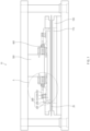
- FIG. 1 is a schematic front view illustrating a pouch molding apparatus 10 according to Embodiment 1 of the present invention.
- the pouch molding apparatus 10 may be an apparatus for molding a pouch used for manufacturing a secondary battery, and specifically, may be used for molding a cup part having an accommodation space for accommodating an electrode assembly.
- the pouch molding apparatus according to Embodiment 1 of the present invention may include a die 100, a punch 200, and an elevator 300.
- the pouch molding apparatus 10 may require a recessed space having the same shape as the accommodation space for accommodating the electrode assembly to form the pouch.
- the pouch molding apparatus 10 according to Embodiment 1 of the present invention may include the die 100.
- the die 100 may be disposed below the pouch molding apparatus 10 and may have a flat plate shape on a surface facing the punch 200 to be described later. However, this is only one example and is not necessarily limited thereto.
- the die 100 may have a die groove 110 recessed into a shape in which the pouch film 20 is formed at a center of a top surface thereof. That is, the die groove 110 may be formed as a space into which the punch 200 is introduced.
- the punch 200 may press the pouch film 20 disposed on the die 100 while moving into the die groove 110 formed in the die 100, and thus, the pouch film 20 may be molded in the shape of the die groove 110.
- the pouch used for manufacturing a pouch-type secondary battery may include a space having a rectangular shape when viewed downward from the top to accommodate the electrode assembly.
- the die groove 110 formed in the die 100 according to the present invention may form a rectangular parallelepiped-shaped empty space.
- the space of the die groove 110 is not necessarily limited thereto and may vary depending on the shape of the required pouch.
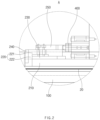
- FIG. 2 is a schematic enlarged view illustrating a portion A of FIG. 1 .
- the pouch molding apparatus 10 may include the punch 200.
- the punch 200 may have the same shape as the space formed by the die groove 110. However, since the punch 200 presses the pouch film 20 while being introduced into the die groove 110, an area of a bottom surface of the punch 200 may be less than that of a bottom surface of the die groove 110.
- the punch 200 may descend to be inserted into the die groove 110, but also the die 100 may ascend so that the punch 200 is inserted into the die groove 110 to press the pouch film 20.
- the punch 200 descends to be inserted into the die groove 110 up to a specific depth will be described as an example.
- the punch 200 may be disposed above the die groove 110 so as to be movable vertically.
- the pouch film 20 to be molded may be disposed on the top surface of the die 100 or disposed between the die 100 and the punch 200, and the punch 200 may descend toward the pouch film 20 disposed at a predetermined position. While the punch 200 descends toward the pouch film 20, the punch 200 may descend together with the pouch film 20 from the moment at which the punch 200 is in contact with the pouch film 20.
- the punch 200 may descend up to the inside of the die groove 110 by a set depth together with the pouch film 20, and after the pouch film 20 is formed while descending to a set depth together with the punch 200, the descending of the punch 200 may be stopped. When the molding of the pouch film 20 is completed, the punch 200 may ascend toward the original position again.
- the pouch molding apparatus 10 may include the elevator 300.
- the elevator 300 may be connected to an upper portion of the punch 200 to move the punch 200 vertically while approaching to and separated from the die groove 110.
- the elevator 300 is not particularly limited in shape as long as the elevator 300 moves the punch 200 by being connected to the punch 200.
- the elevator 300 may have a cylinder shape capable of moving the punch 200 vertically using a pressure or the like.
- the punch 200 may include various components that are necessary for forming the pouch. Among them, the body part 210 of the punch 200 may be inserted into the die groove 110 together with the pouch film 20 disposed between the die 100 and the punch 200.
- the body part 210 may have a shape in which the pouch film 20 is easily inserted into the die groove 110 by pressing the pouch film 20.
- the body part 210 may have a rectangular parallelepiped shape. Therefore, since the bottom surface of the body part 210 presses the pouch film 20 to descend into the die groove 110 by a set depth, the body part 210 may preferably have a flat bottom surface. Since the shape of the body part 210 described in the present invention is merely an example, the present invention is not limited thereto.
- the pouch molding apparatus 10 is characterized in that an additional molding process of pressing toward both directions after molding due to the descending of the punch 200.
- the punch 200 may include a pressing part 220.
- the pressing part 220 may be provided on each of both surfaces of the body part 210 to press the pouch film 20 toward an inner surface of the die groove 110. Particularly, after the punch 200 descends together with the pouch film 20 up to the inside of the die groove 110 by a set depth, the pressing part 220 may press the pouch film 20 toward the inner surface formed on each of both sides of the die groove 110.
- the body part 210 when the body part 210 has a rectangular parallelepiped shape having a rectangular bottom surface, the body part 210 may include two surfaces including two long sides among rectangular four sides of the bottom surface.
- An interval between the pressing part 220 and the die groove 110 may be reduced through a process in which the pressing part 220 of the punch 200 presses the pouch film 20 toward the inner surface of the die groove 110. That is, the interval between the pouch film 20 and the inner surface of the die groove 110 may be reduced, and the molded capacity of the pouch film 20 may increase.
- the interval between the pressing part 220 and the die groove 110 which is about 2.5 mm before the pressing of the pressing part 220, may be reduced to about 0.5 mm after the pressing. That is, the interval between the pressing part 220 and the die groove 110 may be reduced by about 4 mm through adding up both the surfaces, and a degree of molding of the pouch film 20 may be changed.
- the pouch molding apparatus 10 may generate an effect of increasing in capacity while securing the clearance through the molding process using the pressing part 220 of the punch 200.
- a bottom surface of the body part 210 and a bottom surface of the pressing part 220 may be disposed on one plane.
- the body part 210 and the pressing part 220 of the punch 200 may simultaneously descend to press the pouch film 20.
- both the bottom surfaces of the body part 210 and the pressing part 220 may be in contact with the pouch film 20.
- the bottom surfaces of the body part 210 and the pressing part 220 are disposed on the one plane, one surface of the pouch film 20 pressed by the bottom surfaces of the body part 210 and the pressing part 220 may be molded into the flat surface.
- an uneven surface may be formed on one surface of the pouch film 20 due to a height difference between the bottom surfaces.
- the bottom surfaces of the body part 210 and the pressing part 220 disposed on the one plane may generate an effect of forming the even surface of the molded pouch.
- An edge of the bottom surface of the pressing part 220, which is in contact with the pouch film 20, may have a rounded shape.
- the process of pressing the pouch film 20 toward the inner surface of the die groove 110 by the pressing part 220 is a process added after the punch 200 presses the pouch film 20 while the descending. Therefore, a problem such as tearing by the edge that is in contact with the pouch film 20 on the bottom surface of the pressing part 220 may occur on the surface of the pouch film 20 that is molded already. In order to reduce possibility of occurrence of such the problem, a portion of the edge of the pressing part 220 may be processed to be rounded.
- the pressing part 220 of the punch 200 may include a horizontal portion 221 and a vertical portion 222.
- the horizontal portion 221 may be disposed above the body part 210, and the vertical portion 222 may extend downward from one side of the horizontal portion 221 and be disposed on an outer surface of the body part 210.
- the horizontal portion 221 may have a rectangular parallelepiped shape having a rectangular cross-section of which a width is greater than a length.
- the vertical portion 222 may have a rectangular parallelepiped shape having a rectangular cross-section of which a length is less than a width.
- the pressing part 220 may have a i-shaped cross-section or a reversed ⁇ -shaped cross-section when viewed from the front. Since the shape of the pressing part 220 according to Embodiment 1 is merely one example, this embodiment is not limited thereto.
- the pressing part 220 may easily obtain force that is necessary for pressing in the horizontal direction due to the horizontal portion 221 of the pressing part 220 and press the inner surface of the pouch film 20 due to the vertical portion 222.
- a bottom surface of the horizontal portion 221 and a top surface of the body part 210 may be spaced apart from each other.
- the horizontal movement of the pressing part 220 may be efficient.
- an additional configuration for improving efficiency of the horizontal movement of the pressing part 220 may be disposed.
- the punch 200 of the pouch molding apparatus 10 according to Embodiment 1 of the present invention may further include a linear motion guide 230.
- the linear motion guide 230 may be a configuration capable of guiding a linear motion to perform the linear motion that helps a ball inside so as to perform an infinite circulation motion.
- the linear motion guide 230 may be disposed between the top surface of the body part 210 and the bottom surface of the horizontal portion 221. As described above, when the bottom surface of the horizontal portion 221 and the top surface of the body part 210 are spaced apart from each other, the linear motion guide 230 may be disposed in the empty space between the horizontal portion 221 and the body part 210.
- the linear motion guide 230 may guide the horizontal movement of the pressing part 220. That is, when the pressing part 220 presses the pouch film 20 toward the inner surface of the die groove 110, efficient movement of the pressing part 220 may occur.
- the punch 200 of the pouch molding apparatus 10 according to Embodiment 1 of the present invention may further include a heating part 240.
- the heating part 240 may be disposed adjacent to the pressing part 220 to apply heat to the pouch film 20 pressed by the pressing part 220. That is, the heating part 240 may additionally apply heat to the pouch film 20 after the pressing part 220 presses the pouch film 20.
- the heating part 240 applies the heat to the pouch film 20 in various manners, a detailed description thereof will be omitted.
- the heating part 240 may be disposed at an opposite side of the body part 210 with respect to the pressing part 220. That is, the heating part 240 may be disposed to be in contact with the inner surface of the pouch film 20 pressed by the pressing part 220.
- the heating part 240 may apply the heat after pressing the inner surface of the pouch film 20 together when the pressing part 220 presses the inner surface of the pouch film 20.
- the heating part 240 may be disposed on a portion of the surface on which the pressing part 220 presses the inner surface of the pouch film 20 or may be disposed on the entire surface.
- the heating part 240 may directly apply the heat to the surface of the pouch film 20, the effect of improving the efficiency of the heat application process may occur.
- the pouch molding apparatus 10 may further include a cylinder 400.
- the cylinder 400 may be disposed above the body part 210 to move the pressing part 220 toward the inner surface of the die groove 110 so that the pressing part 220 presses the inner surface of the pouch film 20. That is, the cylinder 400 may provide force for the horizontal movement of the pressing part 220.
- the cylinder 400 should be able to push the pressing part 220 toward the inner surface of the die groove 110 or pull the pressing part 220 back to its original position.
- the cylinder 400 may be a pressure cylinder or a hydraulic cylinder capable of providing force in the horizontal direction to the pressing part 220 through a configuration such as a piston. Since the pressure cylinder or hydraulic cylinder is a commonly used and well-known configuration, a detailed description thereof will be omitted. Since this is merely examples of the cylinder 400, this embodiment is not necessarily limited thereto, and the force may be provided to the pressing part 220 in other manners.
- the cylinder 400 may be coupled to a circumference of the elevator 300 to ensure stability.
- movement such as vibration that may occur in the cylinder 400 when the cylinder 400 provides force for moving the pressing part 220 may be reduced.
- the punch 200 of the pouch molding apparatus 10 according to Embodiment 1 of the present invention further includes a coupling part 250.
- the coupling part 250 may be disposed above the horizontal portion 221 to couple the cylinder 400 and the pressing part 220 to each other.
- the coupling part 250 may have one side connected to the pressing part 220 and the other side connected to the cylinder 400 to couple the pressing part 220 to the cylinder 400.
- a component such as a pin or bolt may pass through one side of the coupling part 250 and the horizontal portion 221 of the pressing part 220 in the vertical direction so as to be connected to each other.
- a portion of the cylinder 400 extending toward the coupling part 250 may be connected in a manner such as being fitted. Since this is merely an example of the connection method, the connection methods between the coupling part 250 and the pressing part 220 and between the coupling part 250 and the cylinder 400 may vary.
- the cylinder 400 When an additional component such as the linear motion guide 230 is disposed below the horizontal portion 221, the cylinder 400 may be directly connected to the pressing part 220, and thus, it difficult to apply force. Even in this case, the coupling part 250 may generate an effect in which the force provided by the cylinder 400 is efficiently transmitted to the pressing part 220.
- FIG. 3 is a schematic front view illustrating a state in which the punch of the pouch molding apparatus approaches the die groove according to Embodiment 1 of the present invention
- FIG. 4 is a schematic front view illustrating a state in which the pressing part of the pouch molding apparatus presses the pouch film according to Embodiment 1 of the present invention.
- a portion of the punch 200 may be inserted into the die groove 110 formed in the die 100 together with the pouch film 20 while the punch 200 descends in the direction of the die 100 by the elevator 300.
- the bottom surface of the punch 200 may descend to the inside of the die groove 110 by a set depth together with the pouch film 20. Through this process, a depth of molding may be secured.
- the pressing part 220 of the punch 200 may press the pouch film 20 toward the inner surface of the die groove 110.
- the pressing part 220 connected to the coupling part 250 may press the pouch film 20 while moving toward the inner surface of the die groove 110 by the linear motion guide 230.
- the heating part 240 may apply heat to the pouch film 20 while the pressing part 220 presses the pouch film 20.
- the pouch molding apparatus 10 according to Embodiment 1 of the present invention may increase in molding depth and capacity of the pouch to generate an effect of improving moldability of a space accommodating the electrode assembly.
- the present invention provides a pouch molding method as Embodiment 2.
- FIG. 5 is a schematic flowchart illustrating a pouch molding method according to Embodiment 2 of the present invention.
- a pouch molding method may include a disposing process (S10), a primary molding process (S20), and a secondary molding process (S30).
- a process of disposing the pouch film 20 to be molded in the pouch molding apparatus 10 may be performed.
- the pouch film 20 may be disposed between a die 100 having a die groove 110 and a punch 200 disposed above the die groove 110.
- the pouch film When disposing the pouch film 20, the pouch film may be disposed to be in contact with a top surface of the die 100 above the die groove 110, or the pouch film 20 may be disposed between the die 100 and the punch 200 so as not to be in contact with the die 100.
- the primary molding process (S20) may be performed.
- the pouch film 20 may be molded while a body part 210 of the punch 200 is inserted into the die groove 110 together with the pouch film 20.
- the punch 200 is inserted into the die groove 110 together with the pouch film 20 to form a space in the pouch film 20 to accommodate the electrode assembly.
- An elevator 300 connected to an upper portion of the punch 200 may move the punch 200 vertically, and the primary molding process (S20) may proceed while the punch 200 descends by the elevator 300.
- the body part 210 at a lower portion of the punch 200 may be in contact with the pouch film 20 to press the pouch film 20. Therefore, after the primary molding process (S20) is performed, a bottom surface of the body part 210 may be in a state of descending up to the inside of the die groove 110 by a set depth.
- the secondary molding process (S30) may proceed.
- a plurality of pressing parts 220 provided at both sides of the body part 210 may press the pouch film 20 toward an inner surface of the die groove 110 after the primary molding process (S20).
- the pressing parts 220 may be provided at both the sides of the body part 210, respectively. As the pressing part 220 horizontally moves in a direction away from the body part 210 to press the pouch film 20, additional molding may be possible on the pouch film 20.
- An electrode assembly accommodation space formed in the pouch by the secondary molding process (S30) may secure more capacity.
- the pressing parts 220 may press the pouch film 20 while a heating part 240 applies heat to the pouch film 20.
- the heating part 240 may be provided on an outer surface of the pressing part 220 to apply the heat to the pouch film 20.
- the heating part 240 may also be in contact with the pouch film 20 to press the pouch film 20 together with the pressing part 220, and simultaneously, to apply the heat to the pouch film 20.
- the heating part 240 applies the heat to the pouch film 20, molding efficiency of the secondary molding process may be improved.
- the pressing part 220 may maintain a state in which the pouch film 20 is pressed for a predetermined time.
- the pressing part 220 may be stopped for a predetermined time period, and when the predetermined time period elapses, the pressing part 220 may move to its original position.
- a process in which the punch 200 is spaced apart from the die 100 through the ascending motion of the elevator 300 to ascend to the original position may be additionally performed.
- a detailed description of the processes that may generally be involved is omitted.
- capacity may increase by the secondary molding process (S30) in a state in which a depth of the molding is advantageously secured by securing a large clearance in the primary molding process (S20).
- a shape of the pouch molded according to the pouch molding method using the pouch molding apparatus of the present invention may be molded so that the inner surface of the pouch film 20 has a shape closer to that of an outer surface of the punch 200 compared to a case in which the process, in which the pressing part 220 of the punch 200 for pressing the pouch film 20 is not added.
Landscapes
- Engineering & Computer Science (AREA)
- Mechanical Engineering (AREA)
- Chemical & Material Sciences (AREA)
- Chemical Kinetics & Catalysis (AREA)
- Electrochemistry (AREA)
- General Chemical & Material Sciences (AREA)
- Physics & Mathematics (AREA)
- Thermal Sciences (AREA)
- Making Paper Articles (AREA)
- Sealing Battery Cases Or Jackets (AREA)
- Blow-Moulding Or Thermoforming Of Plastics Or The Like (AREA)
Abstract
Description
- The present application claims the benefit of the priority of
Korean Patent Application No. 10-2021-0183205, filed on December 20, 2021 - The present invention relates to a pouch molding apparatus and method, and more particularly, to a pouch molding apparatus and method for molding a pouch used in manufacturing a secondary battery.
- In recent years, the price of energy sources increases due to the depletion of fossil fuels, the interest in environmental pollution is amplified, and the demand for ecofriendly alternative energy sources is becoming an indispensable factor for future life. Accordingly, studies on various power generation technologies such as solar power, wind power, and tidal power are continuing, and power storage devices such as batteries for more efficiently using the generated electrical energy are also of great interest.
- Furthermore, as technology development and demand for electronic mobile devices and electric vehicles using batteries increase, the demands for batteries as energy sources are rapidly increasing. Thus, many studies on batteries which are capable of meeting various demands have been conducted.
- Batteries storing electrical energy may be generally classified into primary batteries and secondary batteries. Such a primary battery is a disposable consumable battery. On the other hand, such a secondary battery is a chargeable battery that is manufactured by using a material in which oxidation and reduction processes between current and the material are capable of being repeated. That is, when the reduction reaction to the material is performed by the current, power is charged. When the oxidation reaction to the material is performed by the current, power is discharged. Such charging-discharging are repeatedly performed to generate electricity.
- In general, types of the secondary battery include nickel cadmium batteries, nickel hydrogen batteries, lithium ion batteries, and lithium ion polymer batteries. In particular, in terms of materials, there is a high demand for the lithium secondary batteries such as the lithium ion batteries, the lithium ion polymer batteries, and the like, which have advantages such as a high energy density, a discharge voltage, and output stability.
- Such a secondary battery is manufactured by accommodating an electrode assembly, in which stacked unit cells are gathered, in a specific case. Such a secondary battery is classified into a pouch-type secondary battery and a can-type secondary battery according to a material of a case accommodating the electrode assembly.
- Among them, the pouch-type secondary battery is manufactured in a manner, in which an electrode assembly is accommodated in a pouch made of a flexible polymer material having a variable shape. A pouch that is a case of the pouch-type secondary battery is manufactured by forming a cup part on a pouch film made of a flexible material. That is, when the cup part having an accommodation space for accommodating the electrode assembly is formed in the pouch film, the electrode assembly is accommodated in the accommodation space of the cup part, and a sealing part is sealed to manufacture a secondary battery.
- In a process of forming a cup part in the pouch film as described above, a pouch molding apparatus is required, but there is a problem in that a depth and capacity of the cup part molded by the pouch molding apparatus according to the related art are insufficient.
- In order to solve this problem, there is a need for a method capable of increasing in molding depth and capacity of the cup part formed by the pouch molding.
- The present invention has been made to solve the above problem, and an object of the present invention is to a pouch molding apparatus in which a specific process is added in a pouch molding process to deform a pouch so that a large amount of clearance than an existing amount is secured to increase in capacity in an advantageous state for depth molding. That is, the present invention provides a pouch molding apparatus that is capable of improving moldability of a pouch to increase in depth and capacity of a pouch cup part.
- A pouch molding apparatus according to the present invention includes a die in which a die groove recessed in a shape, in which a pouch is molded, is formed, and a punch disposed above the die groove, wherein the punch may include a body part inserted into the die groove together with a pouch film disposed between the die and the punch, and a pressing part provided on each of both surfaces of the body part to press the pouch film toward an inner surface of the die groove.
- In the punch, a bottom surface of the body part and a bottom surface of the pressing part may be disposed on one plane.
- The pressing part may include a horizontal portion disposed above the body part, and a vertical portion extending downward from one side of the horizontal portion and disposed on an outer surface of the body part to press an inner surface of the pouch film.
- In the punch, a bottom surface of the horizontal portion and a top surface of the body part may be spaced apart from each other.
- The punch may further include a linear motion guide disposed between a top surface of the body part and a bottom surface of the horizontal portion to guide movement of the pressing part.
- The punch may further include a heating part disposed adjacent to the pressing part to apply heat to the pouch film pressed by the pressing part.
- The heating part may be disposed at an opposite side of the body part with respect to the pressing part.
- The pouch molding apparatus may further include a cylinder disposed above the body part to move the pressing part toward an inner surface of the die groove.
- The pouch molding apparatus may further include an elevator connected to an upper portion of the punch so that the punch approaches the die groove and is spaced apart from the die groove, wherein the cylinder may be coupled to a circumference of the elevator.
- The punch may further include a coupling part configured to couple the cylinder to the pressing part.
- A pouch molding method according to the present invention may include a disposing process of disposing a pouch film between a die, in which a die groove is formed, and a punch disposed above the die groove, a primary molding process of molding the pouch film while a body part of the punch is inserted into the die groove together with the pouch film, and a secondary molding process of allowing a plurality of pressing parts respectively provided on both surfaces of the body part to press the pouch film toward an inner surface of the die groove after the primary molding process.
- In the secondary molding process, the pressing parts may press the pouch film, and simultaneously, a heating part provided in each of the pressing parts may apply heat.
- In the secondary molding process, a state in which the pressing parts press the pouch film toward the inner surface of the die groove may be maintained for a predetermined time.
- The pouch molding apparatus according to the present invention may include the die, in which the die groove recessed in a shape, in which a pouch is molded, is formed, and the punch disposed above the die groove, and the punch may include the body part inserted into the die groove together with the pouch film disposed between the die and the punch and the pressing part provided on each of both the surfaces of the body part to press the pouch film toward the inner surface of the die groove.
- Therefore, the pouch molding apparatus may deform the pouch by adding the specific process in the pouch molding process so that the large amount of clearance than the existing amount is secured to increase in capacity in the advantageous state for the depth molding. Therefore, the moldability of the pouch may be improved to increase in depth and capacity of the cup part of the pouch.
-
-
FIG. 1 is a schematic front view illustrating a pouch molding apparatus according toEmbodiment 1 of the present invention. -
FIG. 2 is a schematic enlarged view illustrating a portion A ofFIG. 1 . -
FIG. 3 is a schematic front view illustrating a state in which a punch of the pouch molding apparatus approaches a die groove according toEmbodiment 1 of the present invention. -
FIG. 4 is a schematic front view illustrating a state in which a pressing part of the pouch molding apparatus presses a pouch film according toEmbodiment 1 of the present invention. -
FIG. 5 is a schematic flowchart illustrating a pouch molding method according to Embodiment 2 of the present invention. - Hereinafter, preferred embodiments of the present invention will be described in detail with reference to the accompanying drawings so that those of ordinary skill in the art can easily carry out the present invention. However, the present invention may be implemented in several different forms and is not limited or restricted by the following examples.
- In order to clearly explain the present invention, detailed descriptions of portions that are irrelevant to the description or related known technologies that may unnecessarily obscure the gist of the present invention have been omitted, and in the present specification, reference symbols are added to components in each drawing. In this case, the same or similar reference numerals are assigned to the same or similar elements throughout the specification.
- Also, terms or words used in this specification and claims should not be restrictively interpreted as ordinary meanings or dictionary-based meanings, but should be interpreted as meanings and concepts conforming to the scope of the present invention on the basis of the principle that an inventor can properly define the concept of a term to describe and explain his or her invention in the best ways.
- The present invention provides a pouch molding apparatus as
Embodiment 1. -
FIG. 1 is a schematic front view illustrating apouch molding apparatus 10 according toEmbodiment 1 of the present invention. - The
pouch molding apparatus 10 may be an apparatus for molding a pouch used for manufacturing a secondary battery, and specifically, may be used for molding a cup part having an accommodation space for accommodating an electrode assembly. Referring toFIG. 1 , the pouch molding apparatus according toEmbodiment 1 of the present invention may include adie 100, apunch 200, and anelevator 300. - The
pouch molding apparatus 10 may require a recessed space having the same shape as the accommodation space for accommodating the electrode assembly to form the pouch. As an example of a configuration including such a space, thepouch molding apparatus 10 according toEmbodiment 1 of the present invention may include thedie 100. - The die 100 may be disposed below the
pouch molding apparatus 10 and may have a flat plate shape on a surface facing thepunch 200 to be described later. However, this is only one example and is not necessarily limited thereto. - The
die 100 may have adie groove 110 recessed into a shape in which thepouch film 20 is formed at a center of a top surface thereof. That is, thedie groove 110 may be formed as a space into which thepunch 200 is introduced. Thepunch 200 may press thepouch film 20 disposed on thedie 100 while moving into thedie groove 110 formed in thedie 100, and thus, thepouch film 20 may be molded in the shape of thedie groove 110. - In general, the pouch used for manufacturing a pouch-type secondary battery may include a space having a rectangular shape when viewed downward from the top to accommodate the electrode assembly. Thus, the
die groove 110 formed in thedie 100 according to the present invention may form a rectangular parallelepiped-shaped empty space. However, the space of thedie groove 110 is not necessarily limited thereto and may vary depending on the shape of the required pouch. -
FIG. 2 is a schematic enlarged view illustrating a portion A ofFIG. 1 . - As an example of a configuration for pressing the die 100 described above, the
pouch molding apparatus 10 according toEmbodiment 1 of the present invention may include thepunch 200. - Since the
punch 200 molds thepouch film 20 while being inserted into thedie groove 110 formed in thedie 100, thepunch 200 may have the same shape as the space formed by thedie groove 110. However, since thepunch 200 presses thepouch film 20 while being introduced into thedie groove 110, an area of a bottom surface of thepunch 200 may be less than that of a bottom surface of thedie groove 110. - As an example of a method for pressing the
pouch film 20 by thepunch 200, not only thepunch 200 may descend to be inserted into thedie groove 110, but also thedie 100 may ascend so that thepunch 200 is inserted into thedie groove 110 to press thepouch film 20. In the present invention, a case in which thepunch 200 descends to be inserted into thedie groove 110 up to a specific depth will be described as an example. - The
punch 200 may be disposed above thedie groove 110 so as to be movable vertically. Thepouch film 20 to be molded may be disposed on the top surface of the die 100 or disposed between the die 100 and thepunch 200, and thepunch 200 may descend toward thepouch film 20 disposed at a predetermined position. While thepunch 200 descends toward thepouch film 20, thepunch 200 may descend together with thepouch film 20 from the moment at which thepunch 200 is in contact with thepouch film 20. Thepunch 200 may descend up to the inside of thedie groove 110 by a set depth together with thepouch film 20, and after thepouch film 20 is formed while descending to a set depth together with thepunch 200, the descending of thepunch 200 may be stopped. When the molding of thepouch film 20 is completed, thepunch 200 may ascend toward the original position again. - As an example of a configuration for vertically moving the
punch 200 disposed above thedie groove 110, thepouch molding apparatus 10 according toEmbodiment 1 of the present invention may include theelevator 300. - The
elevator 300 may be connected to an upper portion of thepunch 200 to move thepunch 200 vertically while approaching to and separated from thedie groove 110. - The
elevator 300 is not particularly limited in shape as long as theelevator 300 moves thepunch 200 by being connected to thepunch 200. Preferably, theelevator 300 may have a cylinder shape capable of moving thepunch 200 vertically using a pressure or the like. - Referring to
FIG. 2 , thepunch 200 may include various components that are necessary for forming the pouch. Among them, thebody part 210 of thepunch 200 may be inserted into thedie groove 110 together with thepouch film 20 disposed between the die 100 and thepunch 200. - The
body part 210 may have a shape in which thepouch film 20 is easily inserted into thedie groove 110 by pressing thepouch film 20. As an example, thebody part 210 may have a rectangular parallelepiped shape. Therefore, since the bottom surface of thebody part 210 presses thepouch film 20 to descend into thedie groove 110 by a set depth, thebody part 210 may preferably have a flat bottom surface. Since the shape of thebody part 210 described in the present invention is merely an example, the present invention is not limited thereto. - The
pouch molding apparatus 10 according to the present invention is characterized in that an additional molding process of pressing toward both directions after molding due to the descending of thepunch 200. As an example of a configuration for the additional molding process, thepunch 200 may include apressing part 220. - The
pressing part 220 may be provided on each of both surfaces of thebody part 210 to press thepouch film 20 toward an inner surface of thedie groove 110. Particularly, after thepunch 200 descends together with thepouch film 20 up to the inside of thedie groove 110 by a set depth, thepressing part 220 may press thepouch film 20 toward the inner surface formed on each of both sides of thedie groove 110. - Here, when the
body part 210 has a rectangular parallelepiped shape having a rectangular bottom surface, thebody part 210 may include two surfaces including two long sides among rectangular four sides of the bottom surface. - An interval between the
pressing part 220 and thedie groove 110 may be reduced through a process in which thepressing part 220 of thepunch 200 presses thepouch film 20 toward the inner surface of thedie groove 110. That is, the interval between thepouch film 20 and the inner surface of thedie groove 110 may be reduced, and the molded capacity of thepouch film 20 may increase. - As an example of deformation by the pressing, the interval between the
pressing part 220 and thedie groove 110, which is about 2.5 mm before the pressing of thepressing part 220, may be reduced to about 0.5 mm after the pressing. That is, the interval between thepressing part 220 and thedie groove 110 may be reduced by about 4 mm through adding up both the surfaces, and a degree of molding of thepouch film 20 may be changed. - When molding the pouch used in the pouch-type secondary battery, a large clearance between the die 100 and the
punch 200 may be secured, and thus, this may be advantageous in molding a depth of the space in which the electrode assembly is accommodated. Thepouch molding apparatus 10 according to the present invention may generate an effect of increasing in capacity while securing the clearance through the molding process using thepressing part 220 of thepunch 200. - As an example of a configuration for molding the
pouch film 20 into a flat shape of a lower portion when molding thepouch film 20 due to the descending of thepunch 200, in thepunch 200 of thepouch molding apparatus 10 according toEmbodiment 1 of the present invention, a bottom surface of thebody part 210 and a bottom surface of thepressing part 220 may be disposed on one plane. - The
body part 210 and thepressing part 220 of thepunch 200 may simultaneously descend to press thepouch film 20. Thus, both the bottom surfaces of thebody part 210 and thepressing part 220 may be in contact with thepouch film 20. If the bottom surfaces of thebody part 210 and thepressing part 220 are disposed on the one plane, one surface of thepouch film 20 pressed by the bottom surfaces of thebody part 210 and thepressing part 220 may be molded into the flat surface. However, if the bottom surfaces of thebody part 210 and thepressing part 220 are not disposed on the one plane, an uneven surface may be formed on one surface of thepouch film 20 due to a height difference between the bottom surfaces. - Thus, the bottom surfaces of the
body part 210 and thepressing part 220 disposed on the one plane may generate an effect of forming the even surface of the molded pouch. - An edge of the bottom surface of the
pressing part 220, which is in contact with thepouch film 20, may have a rounded shape. The process of pressing thepouch film 20 toward the inner surface of thedie groove 110 by thepressing part 220 is a process added after thepunch 200 presses thepouch film 20 while the descending. Therefore, a problem such as tearing by the edge that is in contact with thepouch film 20 on the bottom surface of thepressing part 220 may occur on the surface of thepouch film 20 that is molded already. In order to reduce possibility of occurrence of such the problem, a portion of the edge of thepressing part 220 may be processed to be rounded. - As an example of a configuration in which the
pressing part 220 of thepunch 200 easily presses thepouch film 20 in a horizontal direction toward the inner surface of thedie groove 110, thepressing part 220 of thepunch 200 of the present invention may include ahorizontal portion 221 and avertical portion 222. - The
horizontal portion 221 may be disposed above thebody part 210, and thevertical portion 222 may extend downward from one side of thehorizontal portion 221 and be disposed on an outer surface of thebody part 210. - When viewed from the front surface with reference to
FIG. 2 , thehorizontal portion 221 may have a rectangular parallelepiped shape having a rectangular cross-section of which a width is greater than a length. When viewed from the front surface with reference toFIG. 2 , thevertical portion 222 may have a rectangular parallelepiped shape having a rectangular cross-section of which a length is less than a width. Thus, thepressing part 220 may have a i-shaped cross-section or a reversed ¬-shaped cross-section when viewed from the front. Since the shape of thepressing part 220 according toEmbodiment 1 is merely one example, this embodiment is not limited thereto. - The
pressing part 220 may easily obtain force that is necessary for pressing in the horizontal direction due to thehorizontal portion 221 of thepressing part 220 and press the inner surface of thepouch film 20 due to thevertical portion 222. - As an example of a configuration for easily moving the
pressing part 220 in the horizontal direction, in thepunch 200 of thepouch molding apparatus 10 according toEmbodiment 1 of the present invention, a bottom surface of thehorizontal portion 221 and a top surface of thebody part 210 may be spaced apart from each other. - If the bottom surface of the
horizontal portion 221 and the top surface of thebody part 210 are spaced apart from each other so that an empty space is formed between thehorizontal portion 221 and thebody part 210, when thepressing part 220 moves in the horizontal direction to press thepouch film 20, since friction does not occur between thehorizontal portion 221 and thebody part 210, the horizontal movement of thepressing part 220 may be efficient. In addition, an additional configuration for improving efficiency of the horizontal movement of thepressing part 220 may be disposed. - As an example of an additional configuration for improving efficiency of the horizontal movement of the
pressing part 220, thepunch 200 of thepouch molding apparatus 10 according toEmbodiment 1 of the present invention may further include alinear motion guide 230. Thelinear motion guide 230 may be a configuration capable of guiding a linear motion to perform the linear motion that helps a ball inside so as to perform an infinite circulation motion. - The
linear motion guide 230 may be disposed between the top surface of thebody part 210 and the bottom surface of thehorizontal portion 221. As described above, when the bottom surface of thehorizontal portion 221 and the top surface of thebody part 210 are spaced apart from each other, thelinear motion guide 230 may be disposed in the empty space between thehorizontal portion 221 and thebody part 210. - The
linear motion guide 230 may guide the horizontal movement of thepressing part 220. That is, when thepressing part 220 presses thepouch film 20 toward the inner surface of thedie groove 110, efficient movement of thepressing part 220 may occur. - As an example of a configuration used in an additional process for efficiently molding the shape of the
pouch film 20, thepunch 200 of thepouch molding apparatus 10 according toEmbodiment 1 of the present invention may further include aheating part 240. - The
heating part 240 may be disposed adjacent to thepressing part 220 to apply heat to thepouch film 20 pressed by thepressing part 220. That is, theheating part 240 may additionally apply heat to thepouch film 20 after thepressing part 220 presses thepouch film 20. - Due to the
heating part 240 applying the heat, an effect of improving molding efficiency may occur compared to when thepouch film 20 is molded only by a pressure. - Since the
heating part 240 applies the heat to thepouch film 20 in various manners, a detailed description thereof will be omitted. - As an example of a configuration for efficiently applying the heat to the
pouch film 20, theheating part 240 may be disposed at an opposite side of thebody part 210 with respect to thepressing part 220. That is, theheating part 240 may be disposed to be in contact with the inner surface of thepouch film 20 pressed by thepressing part 220. - When the
heating part 240 is disposed at the opposite side of thebody part 210 with respect to thepressing part 220, theheating part 240 may apply the heat after pressing the inner surface of thepouch film 20 together when thepressing part 220 presses the inner surface of thepouch film 20. - The
heating part 240 may be disposed on a portion of the surface on which thepressing part 220 presses the inner surface of thepouch film 20 or may be disposed on the entire surface. - Due to the arrangement of the
heating part 240, since theheating part 240 may directly apply the heat to the surface of thepouch film 20, the effect of improving the efficiency of the heat application process may occur. - As an example of a configuration in which the
pressing part 220 provides a pressure for pressing the inner surface of thepouch film 20, thepouch molding apparatus 10 according toEmbodiment 1 of the present invention may further include acylinder 400. - The
cylinder 400 may be disposed above thebody part 210 to move thepressing part 220 toward the inner surface of thedie groove 110 so that thepressing part 220 presses the inner surface of thepouch film 20. That is, thecylinder 400 may provide force for the horizontal movement of thepressing part 220. - The
cylinder 400 should be able to push thepressing part 220 toward the inner surface of thedie groove 110 or pull thepressing part 220 back to its original position. For example, thecylinder 400 may be a pressure cylinder or a hydraulic cylinder capable of providing force in the horizontal direction to thepressing part 220 through a configuration such as a piston. Since the pressure cylinder or hydraulic cylinder is a commonly used and well-known configuration, a detailed description thereof will be omitted. Since this is merely examples of thecylinder 400, this embodiment is not necessarily limited thereto, and the force may be provided to thepressing part 220 in other manners. - The
cylinder 400 may be coupled to a circumference of theelevator 300 to ensure stability. When thecylinder 400 is coupled to theelevator 300, movement such as vibration that may occur in thecylinder 400 when thecylinder 400 provides force for moving thepressing part 220 may be reduced. - As an example of a configuration for efficiently moving the
pressing part 220 by thecylinder 400, thepunch 200 of thepouch molding apparatus 10 according toEmbodiment 1 of the present invention further includes acoupling part 250. - The
coupling part 250 may be disposed above thehorizontal portion 221 to couple thecylinder 400 and thepressing part 220 to each other. Specifically, thecoupling part 250 may have one side connected to thepressing part 220 and the other side connected to thecylinder 400 to couple thepressing part 220 to thecylinder 400. When one side of thecoupling part 250 is connected to thepressing part 220, a component such as a pin or bolt may pass through one side of thecoupling part 250 and thehorizontal portion 221 of thepressing part 220 in the vertical direction so as to be connected to each other. In addition, when the other side of thecoupling part 250 is connected to thecylinder 400, a portion of thecylinder 400 extending toward thecoupling part 250 may be connected in a manner such as being fitted. Since this is merely an example of the connection method, the connection methods between thecoupling part 250 and thepressing part 220 and between thecoupling part 250 and thecylinder 400 may vary. - When an additional component such as the
linear motion guide 230 is disposed below thehorizontal portion 221, thecylinder 400 may be directly connected to thepressing part 220, and thus, it difficult to apply force. Even in this case, thecoupling part 250 may generate an effect in which the force provided by thecylinder 400 is efficiently transmitted to thepressing part 220. -
FIG. 3 is a schematic front view illustrating a state in which the punch of the pouch molding apparatus approaches the die groove according toEmbodiment 1 of the present invention, andFIG. 4 is a schematic front view illustrating a state in which the pressing part of the pouch molding apparatus presses the pouch film according toEmbodiment 1 of the present invention. - The state of the
pouch molding apparatus 10 according to each process will be described with reference toFIGS. 3 and4 . - Referring to
FIG. 3 , in thepouch molding apparatus 10 according toEmbodiment 1 of the present invention, a portion of thepunch 200 may be inserted into thedie groove 110 formed in thedie 100 together with thepouch film 20 while thepunch 200 descends in the direction of thedie 100 by theelevator 300. Thus, the bottom surface of thepunch 200 may descend to the inside of thedie groove 110 by a set depth together with thepouch film 20. Through this process, a depth of molding may be secured. - Referring to
FIG. 4 , in thepouch molding apparatus 10 according toEmbodiment 1 of the present invention, in the state in which the bottom surface of thepunch 200 descends to the inside of thedie groove 110 formed in thedie 100 by a set depth, thepressing part 220 of thepunch 200 may press thepouch film 20 toward the inner surface of thedie groove 110. Specifically, when thecylinder 400 presses thecoupling part 250, thepressing part 220 connected to thecoupling part 250 may press thepouch film 20 while moving toward the inner surface of thedie groove 110 by thelinear motion guide 230. - Additionally, the
heating part 240 may apply heat to thepouch film 20 while thepressing part 220 presses thepouch film 20. - The
pouch molding apparatus 10 according toEmbodiment 1 of the present invention may increase in molding depth and capacity of the pouch to generate an effect of improving moldability of a space accommodating the electrode assembly. - The present invention provides a pouch molding method as Embodiment 2.
- Hereinafter, a detailed description of the same configuration as the
pouch molding apparatus 10 according toEmbodiment 1 of the present invention will be omitted. -
FIG. 5 is a schematic flowchart illustrating a pouch molding method according to Embodiment 2 of the present invention. - Referring to
FIG. 5 , a pouch molding method may include a disposing process (S10), a primary molding process (S20), and a secondary molding process (S30). - First, a process of disposing the
pouch film 20 to be molded in thepouch molding apparatus 10 may be performed. In the disposing process (S10), thepouch film 20 may be disposed between a die 100 having adie groove 110 and apunch 200 disposed above thedie groove 110. - When disposing the
pouch film 20, the pouch film may be disposed to be in contact with a top surface of thedie 100 above thedie groove 110, or thepouch film 20 may be disposed between the die 100 and thepunch 200 so as not to be in contact with thedie 100. - After the disposing process (S10) of disposing the
pouch film 20, the primary molding process (S20) may be performed. In the primary molding process (S20), thepouch film 20 may be molded while abody part 210 of thepunch 200 is inserted into thedie groove 110 together with thepouch film 20. - The
punch 200 is inserted into thedie groove 110 together with thepouch film 20 to form a space in thepouch film 20 to accommodate the electrode assembly. Anelevator 300 connected to an upper portion of thepunch 200 may move thepunch 200 vertically, and the primary molding process (S20) may proceed while thepunch 200 descends by theelevator 300. - The
body part 210 at a lower portion of thepunch 200 may be in contact with thepouch film 20 to press thepouch film 20. Therefore, after the primary molding process (S20) is performed, a bottom surface of thebody part 210 may be in a state of descending up to the inside of thedie groove 110 by a set depth. - After the depth forming of the
pouch film 20 is completed by the primary molding process (S20), the secondary molding process (S30) may proceed. In the secondary molding process (S30), a plurality ofpressing parts 220 provided at both sides of thebody part 210 may press thepouch film 20 toward an inner surface of thedie groove 110 after the primary molding process (S20). - The
pressing parts 220 may be provided at both the sides of thebody part 210, respectively. As thepressing part 220 horizontally moves in a direction away from thebody part 210 to press thepouch film 20, additional molding may be possible on thepouch film 20. - An electrode assembly accommodation space formed in the pouch by the secondary molding process (S30) may secure more capacity.
- In the secondary molding process (S30) of the pouch molding method according to Embodiment 2 of the present invention, the
pressing parts 220 may press thepouch film 20 while aheating part 240 applies heat to thepouch film 20. - Specifically, the
heating part 240 may be provided on an outer surface of thepressing part 220 to apply the heat to thepouch film 20. When theheating part 240 is provided on the outer surface of thepressing part 220, if thepressing parts 220 press thepouch film 20, theheating part 240 may also be in contact with thepouch film 20 to press thepouch film 20 together with thepressing part 220, and simultaneously, to apply the heat to thepouch film 20. - When the
pressing parts 220 press thepouch film 20, and also, theheating part 240 applies the heat to thepouch film 20, molding efficiency of the secondary molding process may be improved. - In the pouch molding method according to Embodiment 2 of the present invention, in the secondary molding process (S30), the
pressing part 220 may maintain a state in which thepouch film 20 is pressed for a predetermined time. - That is, in a state in which the
pressing part 220 presses thepouch film 20 while moving toward an inner surface of thedie groove 110, thepressing part 220 may be stopped for a predetermined time period, and when the predetermined time period elapses, thepressing part 220 may move to its original position. - In the pouch molding method according to Embodiment 2 of the present invention, after the secondary molding process (S30), a process in which the
punch 200 is spaced apart from thedie 100 through the ascending motion of theelevator 300 to ascend to the original position may be additionally performed. As described above, a detailed description of the processes that may generally be involved is omitted. - In the pouch molding method according to Embodiment 2 of the present invention, capacity may increase by the secondary molding process (S30) in a state in which a depth of the molding is advantageously secured by securing a large clearance in the primary molding process (S20).
- In addition, a shape of the pouch molded according to the pouch molding method using the pouch molding apparatus of the present invention may be molded so that the inner surface of the
pouch film 20 has a shape closer to that of an outer surface of thepunch 200 compared to a case in which the process, in which thepressing part 220 of thepunch 200 for pressing thepouch film 20 is not added. - While the embodiments of the present invention have been described with reference to the specific embodiments, it will be apparent to those skilled in the art that various changes and modifications may be made without departing from the spirit and scope of the invention as defined in the following claims.
-
- 10: Pouch molding apparatus
- 20: Pouch film
- 100: Die
- 110: Die groove
- 200: Punch
- 210: Body part
- 220: Pressing part
- 221: Horizontal portion
- 222: Vertical portion
- 230: Linear motion guide
- 240: Heating part
- 250: Coupling part
- 300: Elevator
- 400: Cylinder
Claims (13)
- A pouch molding apparatus comprising:a die in which a die groove recessed in a shape, in which a pouch is molded, is formed; anda punch disposed above the die groove,wherein the punch comprises:a body part inserted into the die groove together with a pouch film disposed between the die and the punch; anda pressing part provided on each of both surfaces of the body part to press the pouch film toward an inner surface of the die groove.
- The pouch molding apparatus of claim 1, wherein, in the punch, a bottom surface of the body part and a bottom surface of the pressing part are disposed on one plane.
- The pouch molding apparatus of claim 1, wherein the pressing part comprises:a horizontal portion disposed above the body part; anda vertical portion extending downward from one side of the horizontal portion and disposed on an outer surface of the body part to press an inner surface of the pouch film.
- The pouch molding apparatus of claim 3, wherein, in the punch, a bottom surface of the horizontal portion and a top surface of the body part are spaced apart from each other.
- The pouch molding apparatus of claim 3, wherein the punch further comprises a linear motion guide disposed between a top surface of the body part and a bottom surface of the horizontal portion to guide movement of the pressing part.
- The pouch molding apparatus of claim 1, wherein the punch further comprises a heating part disposed adjacent to the pressing part to apply heat to the pouch film pressed by the pressing part.
- The pouch molding apparatus of claim 6, wherein the heating part is disposed at an opposite side of the body part with respect to the pressing part.
- The pouch molding apparatus of claim 1, further comprising a cylinder disposed above the body part to move the pressing part toward an inner surface of the die groove.
- The pouch molding apparatus of claim 8, further comprising an elevator connected to an upper portion of the punch so that the punch approaches the die groove and is spaced apart from the die groove,
wherein the cylinder is coupled to a circumference of the elevator. - The pouch molding apparatus of claim 8, wherein the punch further comprises a coupling part configured to couple the cylinder to the pressing part.
- A pouch molding method comprising:a disposing process of disposing a pouch film between a die, in which a die groove is formed, and a punch disposed above the die groove;a primary molding process of molding the pouch film while a body part of the punch is inserted into the die groove together with the pouch film; anda secondary molding process of allowing a plurality of pressing parts respectively provided on both surfaces of the body part to press the pouch film toward an inner surface of the die groove after the primary molding process.
- The pouch molding method of claim 11, wherein, in the secondary molding process, the pressing parts press the pouch film, and simultaneously, a heating part provided in each of the pressing parts applies heat.
- The pouch molding method of claim 11, wherein, in the secondary molding process, a state in which the pressing parts press the pouch film toward the inner surface of the die groove is maintained for a predetermined time.
Applications Claiming Priority (2)
| Application Number | Priority Date | Filing Date | Title |
|---|---|---|---|
| KR1020210183205A KR102940422B1 (en) | 2021-12-20 | 2021-12-20 | The apparatus and the method for forming pouch |
| PCT/KR2022/020134 WO2023121095A1 (en) | 2021-12-20 | 2022-12-12 | Apparatus and method for pouch molding |
Publications (3)
| Publication Number | Publication Date |
|---|---|
| EP4316776A1 true EP4316776A1 (en) | 2024-02-07 |
| EP4316776A4 EP4316776A4 (en) | 2024-09-25 |
| EP4316776B1 EP4316776B1 (en) | 2025-09-10 |
Family
ID=86903270
Family Applications (1)
| Application Number | Title | Priority Date | Filing Date |
|---|---|---|---|
| EP22911728.8A Active EP4316776B1 (en) | 2021-12-20 | 2022-12-12 | Pouch molding apparatus and method |
Country Status (8)
| Country | Link |
|---|---|
| US (1) | US12434413B2 (en) |
| EP (1) | EP4316776B1 (en) |
| JP (1) | JP7643584B2 (en) |
| KR (1) | KR102940422B1 (en) |
| CN (1) | CN117157180A (en) |
| ES (1) | ES3046157T3 (en) |
| HU (1) | HUE073166T2 (en) |
| WO (1) | WO2023121095A1 (en) |
Family Cites Families (26)
| Publication number | Priority date | Publication date | Assignee | Title |
|---|---|---|---|---|
| DE742682C (en) * | 1938-04-15 | 1943-12-09 | Dynamit Act Ges Vormals Alfred | Multi-part compression mold for laminates |
| JPH04293920A (en) * | 1991-03-22 | 1992-10-19 | Teijin Ltd | Thermoforming material and thermoform |
| JPH05177697A (en) * | 1991-12-30 | 1993-07-20 | Konan Tokushu Sangyo Kk | Mold for synthetic resin molded item and method for molding thereof |
| FR2863543B1 (en) | 2003-12-16 | 2007-11-02 | Airbus France | METHOD FOR HOT STAMPING FORMING OF COMPLEX TOLERIE COMPONENT PIECES OF COMPOSITE MATERIAL AND TOOLING FOR IMPLEMENTING IT |
| WO2006118442A1 (en) * | 2005-05-03 | 2006-11-09 | Stork Sp Aerospace B.V. | Device for injecting a resin into at least one fibre layer of a fibre- reinforced product to be manufactured |
| JP5342808B2 (en) * | 2008-06-02 | 2013-11-13 | 日本板硝子株式会社 | Wind molding method |
| WO2014065290A1 (en) * | 2012-10-23 | 2014-05-01 | 新日鐵住金株式会社 | Press molding method and bottomed container |
| KR20150003358U (en) | 2014-03-03 | 2015-09-11 | 주식회사 엘지화학 | Secondary Battery Pouch |
| WO2015157877A1 (en) | 2014-04-15 | 2015-10-22 | 赖宗伸 | Manufacturing method for outer covering edge of molded cup lid and product |
| FR3029449B1 (en) * | 2014-12-03 | 2017-10-13 | Pole De Plasturgie De Lest | MOLDING DEVICE FOR MANUFACTURING COMPOSITE MATERIAL PARTS FROM LIQUID POLYMER RESIN. |
| KR102201640B1 (en) * | 2016-05-03 | 2021-01-11 | 주식회사 엘지화학 | Manufacturing Apparatus for Battery Case Capable of Deeply Forming Mounting Portion for Electrode Assembly and Method Using the Same |
| KR102150010B1 (en) | 2016-09-21 | 2020-08-31 | 주식회사 엘지화학 | Deep Drawing Apparatus for Laminated Sheet Capable of Adjusting Tension and Method for Deep Drawing Using the Same |
| CN108288682B (en) | 2017-01-09 | 2020-12-04 | 宁德新能源科技有限公司 | Shell flushing device |
| KR102309535B1 (en) | 2017-06-08 | 2021-10-07 | 주식회사 엘지에너지솔루션 | Forming apparatus and method for secondary battery |
| KR102075618B1 (en) | 2017-09-14 | 2020-02-10 | 주식회사 엘지화학 | Pouch type secondary battery and Apparatus for forming Pouch film |
| DE102018008119B4 (en) * | 2017-10-27 | 2019-06-06 | Kiefel Packaging B.V. | OF A FILM OF THERMOFORMED TANKS, USE OF A METHOD FOR THERMOFORMS OF A FILM, USE OF A TOOLING TOOL |
| KR102176631B1 (en) | 2017-11-28 | 2020-11-09 | 주식회사 엘지화학 | The Method And The Apparatus For Forming Pouch |
| KR102245128B1 (en) | 2018-01-30 | 2021-04-28 | 주식회사 엘지화학 | The Apparatus And The Method For Forming Pouch |
| KR102237954B1 (en) * | 2018-03-06 | 2021-04-08 | 주식회사 엘지화학 | Manufacturing apparatus and method for pouch, manufacturing method for secondary battery |
| JP7052571B2 (en) | 2018-06-04 | 2022-04-12 | トヨタ自動車株式会社 | Molding equipment and manufacturing method of molded products |
| CN109176723B (en) | 2018-08-30 | 2020-11-06 | 中宁县智才技术服务有限公司 | Punching machine for soft package lithium battery outer package aluminum plastic film |
| KR102667401B1 (en) | 2018-11-06 | 2024-05-21 | 주식회사 엘지에너지솔루션 | The Apparatus And The Method For Forming Pouch |
| KR102145494B1 (en) | 2018-11-23 | 2020-08-18 | 주식회사 엘지화학 | Pouch forming device and method, producing facility of secondary battery including the same |
| CN209329063U (en) | 2019-02-28 | 2019-08-30 | 三星(天津)电池有限公司 | Soft-package battery molding die |
| JP2020179419A (en) * | 2019-04-26 | 2020-11-05 | キヤノンマシナリー株式会社 | Drawer forming device, draw forming method, secondary battery manufacturing device, and secondary battery manufacturing method |
| DE102020101088A1 (en) | 2020-01-17 | 2021-07-22 | Volkswagen Aktiengesellschaft | Process for forming metal composite foils for battery cells |
-
2021
- 2021-12-20 KR KR1020210183205A patent/KR102940422B1/en active Active
-
2022
- 2022-12-12 ES ES22911728T patent/ES3046157T3/en active Active
- 2022-12-12 CN CN202280028769.7A patent/CN117157180A/en active Pending
- 2022-12-12 US US18/289,065 patent/US12434413B2/en active Active
- 2022-12-12 JP JP2023556882A patent/JP7643584B2/en active Active
- 2022-12-12 WO PCT/KR2022/020134 patent/WO2023121095A1/en not_active Ceased
- 2022-12-12 EP EP22911728.8A patent/EP4316776B1/en active Active
- 2022-12-12 HU HUE22911728A patent/HUE073166T2/en unknown
Also Published As
| Publication number | Publication date |
|---|---|
| ES3046157T3 (en) | 2025-12-01 |
| EP4316776A4 (en) | 2024-09-25 |
| WO2023121095A1 (en) | 2023-06-29 |
| US12434413B2 (en) | 2025-10-07 |
| EP4316776B1 (en) | 2025-09-10 |
| US20240217145A1 (en) | 2024-07-04 |
| JP7643584B2 (en) | 2025-03-11 |
| JP2024514761A (en) | 2024-04-03 |
| KR102940422B1 (en) | 2026-03-17 |
| HUE073166T2 (en) | 2026-01-28 |
| CN117157180A (en) | 2023-12-01 |
| KR20230094054A (en) | 2023-06-27 |
Similar Documents
| Publication | Publication Date | Title |
|---|---|---|
| EP3670154B1 (en) | Apparatus for sealing pouch case | |
| KR101467859B1 (en) | Battery Case for Secondary Battery | |
| KR102019850B1 (en) | Lead Bending Machine for Secondary Battery Cell | |
| EP4234196B1 (en) | Secondary battery pouch manufacturing apparatus | |
| EP3032609A1 (en) | Notching apparatus having scrap removing part | |
| KR102023735B1 (en) | Notching Apparatus Having Integral Die and Stripper | |
| KR20170104252A (en) | Jig Apparatus with Improved Compression Adjustment of Coil Spring | |
| KR20160074224A (en) | Battery Pack Comprising Cap Plate Having Inducing Portion of Electrolyte On Inner Surface Thereof | |
| EP4037078B1 (en) | Battery module comprising constant-force spring, and battery pack comprising same | |
| EP4316776B1 (en) | Pouch molding apparatus and method | |
| JP2013089369A (en) | Control valve type lead storage battery | |
| KR20130132093A (en) | Apparatus for forming a packing member for secondary battery | |
| US12337368B2 (en) | Apparatus for manufacturing pouch of secondary battery | |
| KR101818790B1 (en) | Negative tab fixing structure for secondary battery | |
| KR20240100071A (en) | Forming apparatus for pouche | |
| KR20190107397A (en) | Battery module, battery pack comprising the battery module and vehicle comprising the battery pack | |
| CN222830510U (en) | Punch structure and mold | |
| KR20150049456A (en) | Cell case, its manufacturing metallic mold and manufacturing method, battery cell | |
| EP4647228A1 (en) | Molding device and molding method | |
| EP4674596A1 (en) | Molding device | |
| KR20240066764A (en) | Molding apparatus, method for manufacturing pouch cell and battery case | |
| EP4571953A1 (en) | Pouch-type battery case and forming device therefor | |
| EP4241962A1 (en) | Secondary battery pouch manufacturing device and secondary battery pouch manufactured thereby | |
| KR20250011796A (en) | Forming apparatus of pouch cell and manufacturing method of pouch cell | |
| EP4234195A1 (en) | Apparatus for manufacturing secondary battery pouch |
Legal Events
| Date | Code | Title | Description |
|---|---|---|---|
| STAA | Information on the status of an ep patent application or granted ep patent |
Free format text: STATUS: THE INTERNATIONAL PUBLICATION HAS BEEN MADE |
|
| PUAI | Public reference made under article 153(3) epc to a published international application that has entered the european phase |
Free format text: ORIGINAL CODE: 0009012 |
|
| STAA | Information on the status of an ep patent application or granted ep patent |
Free format text: STATUS: REQUEST FOR EXAMINATION WAS MADE |
|
| 17P | Request for examination filed |
Effective date: 20231030 |
|
| AK | Designated contracting states |
Kind code of ref document: A1 Designated state(s): AL AT BE BG CH CY CZ DE DK EE ES FI FR GB GR HR HU IE IS IT LI LT LU LV MC ME MK MT NL NO PL PT RO RS SE SI SK SM TR |
|
| A4 | Supplementary search report drawn up and despatched |
Effective date: 20240827 |
|
| RIC1 | Information provided on ipc code assigned before grant |
Ipc: B29C 51/30 20060101ALI20240821BHEP Ipc: B21D 53/00 20060101ALI20240821BHEP Ipc: B21D 22/20 20060101ALI20240821BHEP Ipc: B29L 31/00 20060101ALI20240821BHEP Ipc: B29C 43/52 20060101ALI20240821BHEP Ipc: B29C 43/36 20060101ALI20240821BHEP Ipc: H01M 50/105 20210101ALI20240821BHEP Ipc: B29C 51/08 20060101AFI20240821BHEP |
|
| DAV | Request for validation of the european patent (deleted) | ||
| DAX | Request for extension of the european patent (deleted) | ||
| GRAP | Despatch of communication of intention to grant a patent |
Free format text: ORIGINAL CODE: EPIDOSNIGR1 |
|
| STAA | Information on the status of an ep patent application or granted ep patent |
Free format text: STATUS: GRANT OF PATENT IS INTENDED |
|
| INTG | Intention to grant announced |
Effective date: 20250603 |
|
| GRAS | Grant fee paid |
Free format text: ORIGINAL CODE: EPIDOSNIGR3 |
|
| P01 | Opt-out of the competence of the unified patent court (upc) registered |
Free format text: CASE NUMBER: APP_31595/2025 Effective date: 20250701 |
|
| GRAA | (expected) grant |
Free format text: ORIGINAL CODE: 0009210 |
|
| STAA | Information on the status of an ep patent application or granted ep patent |
Free format text: STATUS: THE PATENT HAS BEEN GRANTED |
|
| AK | Designated contracting states |
Kind code of ref document: B1 Designated state(s): AL AT BE BG CH CY CZ DE DK EE ES FI FR GB GR HR HU IE IS IT LI LT LU LV MC ME MK MT NL NO PL PT RO RS SE SI SK SM TR |
|
| REG | Reference to a national code |
Ref country code: GB Ref legal event code: FG4D |
|
| REG | Reference to a national code |
Ref country code: CH Ref legal event code: EP |
|
| REG | Reference to a national code |
Ref country code: DE Ref legal event code: R096 Ref document number: 602022021404 Country of ref document: DE |
|
| REG | Reference to a national code |
Ref country code: IE Ref legal event code: FG4D |
|
| REG | Reference to a national code |
Ref country code: ES Ref legal event code: FG2A Ref document number: 3046157 Country of ref document: ES Kind code of ref document: T3 Effective date: 20251201 |
|
| PGFP | Annual fee paid to national office [announced via postgrant information from national office to epo] |
Ref country code: DE Payment date: 20251120 Year of fee payment: 4 |
|
| PG25 | Lapsed in a contracting state [announced via postgrant information from national office to epo] |
Ref country code: NO Free format text: LAPSE BECAUSE OF FAILURE TO SUBMIT A TRANSLATION OF THE DESCRIPTION OR TO PAY THE FEE WITHIN THE PRESCRIBED TIME-LIMIT Effective date: 20251210 |
|
| REG | Reference to a national code |
Ref country code: LT Ref legal event code: MG9D |
|
| PGFP | Annual fee paid to national office [announced via postgrant information from national office to epo] |
Ref country code: AT Payment date: 20260113 Year of fee payment: 4 |
|
| PG25 | Lapsed in a contracting state [announced via postgrant information from national office to epo] |
Ref country code: FI Free format text: LAPSE BECAUSE OF FAILURE TO SUBMIT A TRANSLATION OF THE DESCRIPTION OR TO PAY THE FEE WITHIN THE PRESCRIBED TIME-LIMIT Effective date: 20250910 |
|
| REG | Reference to a national code |
Ref country code: NL Ref legal event code: MP Effective date: 20250910 |
|
| PG25 | Lapsed in a contracting state [announced via postgrant information from national office to epo] |
Ref country code: HR Free format text: LAPSE BECAUSE OF FAILURE TO SUBMIT A TRANSLATION OF THE DESCRIPTION OR TO PAY THE FEE WITHIN THE PRESCRIBED TIME-LIMIT Effective date: 20250910 |
|
| PGFP | Annual fee paid to national office [announced via postgrant information from national office to epo] |
Ref country code: HU Payment date: 20251216 Year of fee payment: 4 Ref country code: FR Payment date: 20251125 Year of fee payment: 4 |
|
| PG25 | Lapsed in a contracting state [announced via postgrant information from national office to epo] |
Ref country code: GR Free format text: LAPSE BECAUSE OF FAILURE TO SUBMIT A TRANSLATION OF THE DESCRIPTION OR TO PAY THE FEE WITHIN THE PRESCRIBED TIME-LIMIT Effective date: 20251211 |
|
| PGFP | Annual fee paid to national office [announced via postgrant information from national office to epo] |
Ref country code: BE Payment date: 20251120 Year of fee payment: 4 |
|
| PG25 | Lapsed in a contracting state [announced via postgrant information from national office to epo] |
Ref country code: SE Free format text: LAPSE BECAUSE OF FAILURE TO SUBMIT A TRANSLATION OF THE DESCRIPTION OR TO PAY THE FEE WITHIN THE PRESCRIBED TIME-LIMIT Effective date: 20250910 |
|
| PG25 | Lapsed in a contracting state [announced via postgrant information from national office to epo] |
Ref country code: LV Free format text: LAPSE BECAUSE OF FAILURE TO SUBMIT A TRANSLATION OF THE DESCRIPTION OR TO PAY THE FEE WITHIN THE PRESCRIBED TIME-LIMIT Effective date: 20250910 |
|
| PG25 | Lapsed in a contracting state [announced via postgrant information from national office to epo] |
Ref country code: BG Free format text: LAPSE BECAUSE OF FAILURE TO SUBMIT A TRANSLATION OF THE DESCRIPTION OR TO PAY THE FEE WITHIN THE PRESCRIBED TIME-LIMIT Effective date: 20250910 Ref country code: PL Free format text: LAPSE BECAUSE OF FAILURE TO SUBMIT A TRANSLATION OF THE DESCRIPTION OR TO PAY THE FEE WITHIN THE PRESCRIBED TIME-LIMIT Effective date: 20250910 |
|
| PG25 | Lapsed in a contracting state [announced via postgrant information from national office to epo] |
Ref country code: RS Free format text: LAPSE BECAUSE OF FAILURE TO SUBMIT A TRANSLATION OF THE DESCRIPTION OR TO PAY THE FEE WITHIN THE PRESCRIBED TIME-LIMIT Effective date: 20251210 |
|
| REG | Reference to a national code |
Ref country code: HU Ref legal event code: AG4A Ref document number: E073166 Country of ref document: HU |
|
| REG | Reference to a national code |
Ref country code: AT Ref legal event code: MK05 Ref document number: 1835454 Country of ref document: AT Kind code of ref document: T Effective date: 20250910 |
|
| PG25 | Lapsed in a contracting state [announced via postgrant information from national office to epo] |
Ref country code: NL Free format text: LAPSE BECAUSE OF FAILURE TO SUBMIT A TRANSLATION OF THE DESCRIPTION OR TO PAY THE FEE WITHIN THE PRESCRIBED TIME-LIMIT Effective date: 20250910 |
|
| PG25 | Lapsed in a contracting state [announced via postgrant information from national office to epo] |
Ref country code: SM Free format text: LAPSE BECAUSE OF FAILURE TO SUBMIT A TRANSLATION OF THE DESCRIPTION OR TO PAY THE FEE WITHIN THE PRESCRIBED TIME-LIMIT Effective date: 20250910 |
|
| PGFP | Annual fee paid to national office [announced via postgrant information from national office to epo] |
Ref country code: ES Payment date: 20260122 Year of fee payment: 4 |
|
| PG25 | Lapsed in a contracting state [announced via postgrant information from national office to epo] |
Ref country code: AT Free format text: LAPSE BECAUSE OF FAILURE TO SUBMIT A TRANSLATION OF THE DESCRIPTION OR TO PAY THE FEE WITHIN THE PRESCRIBED TIME-LIMIT Effective date: 20250910 |
|
| PG25 | Lapsed in a contracting state [announced via postgrant information from national office to epo] |
Ref country code: RO Free format text: LAPSE BECAUSE OF FAILURE TO SUBMIT A TRANSLATION OF THE DESCRIPTION OR TO PAY THE FEE WITHIN THE PRESCRIBED TIME-LIMIT Effective date: 20250910 Ref country code: IT Free format text: LAPSE BECAUSE OF FAILURE TO SUBMIT A TRANSLATION OF THE DESCRIPTION OR TO PAY THE FEE WITHIN THE PRESCRIBED TIME-LIMIT Effective date: 20250910 |
|
| PG25 | Lapsed in a contracting state [announced via postgrant information from national office to epo] |
Ref country code: IS Free format text: LAPSE BECAUSE OF FAILURE TO SUBMIT A TRANSLATION OF THE DESCRIPTION OR TO PAY THE FEE WITHIN THE PRESCRIBED TIME-LIMIT Effective date: 20260110 |
|
| PG25 | Lapsed in a contracting state [announced via postgrant information from national office to epo] |
Ref country code: PT Free format text: LAPSE BECAUSE OF FAILURE TO SUBMIT A TRANSLATION OF THE DESCRIPTION OR TO PAY THE FEE WITHIN THE PRESCRIBED TIME-LIMIT Effective date: 20260112 Ref country code: CZ Free format text: LAPSE BECAUSE OF FAILURE TO SUBMIT A TRANSLATION OF THE DESCRIPTION OR TO PAY THE FEE WITHIN THE PRESCRIBED TIME-LIMIT Effective date: 20250910 |
|
| PG25 | Lapsed in a contracting state [announced via postgrant information from national office to epo] |
Ref country code: EE Free format text: LAPSE BECAUSE OF FAILURE TO SUBMIT A TRANSLATION OF THE DESCRIPTION OR TO PAY THE FEE WITHIN THE PRESCRIBED TIME-LIMIT Effective date: 20250910 Ref country code: SK Free format text: LAPSE BECAUSE OF FAILURE TO SUBMIT A TRANSLATION OF THE DESCRIPTION OR TO PAY THE FEE WITHIN THE PRESCRIBED TIME-LIMIT Effective date: 20250910 |