EP4316768A1 - Vacuum insulated structure - Google Patents
Vacuum insulated structure Download PDFInfo
- Publication number
- EP4316768A1 EP4316768A1 EP23186488.5A EP23186488A EP4316768A1 EP 4316768 A1 EP4316768 A1 EP 4316768A1 EP 23186488 A EP23186488 A EP 23186488A EP 4316768 A1 EP4316768 A1 EP 4316768A1
- Authority
- EP
- European Patent Office
- Prior art keywords
- groove
- trim breaker
- vacuum insulated
- insulated structure
- atm
- Prior art date
- Legal status (The legal status is an assumption and is not a legal conclusion. Google has not performed a legal analysis and makes no representation as to the accuracy of the status listed.)
- Granted
Links
Images




Classifications
-
- F—MECHANICAL ENGINEERING; LIGHTING; HEATING; WEAPONS; BLASTING
- F25—REFRIGERATION OR COOLING; COMBINED HEATING AND REFRIGERATION SYSTEMS; HEAT PUMP SYSTEMS; MANUFACTURE OR STORAGE OF ICE; LIQUEFACTION SOLIDIFICATION OF GASES
- F25D—REFRIGERATORS; COLD ROOMS; ICE-BOXES; COOLING OR FREEZING APPARATUS NOT OTHERWISE PROVIDED FOR
- F25D23/00—General constructional features
- F25D23/02—Doors; Covers
-
- F—MECHANICAL ENGINEERING; LIGHTING; HEATING; WEAPONS; BLASTING
- F25—REFRIGERATION OR COOLING; COMBINED HEATING AND REFRIGERATION SYSTEMS; HEAT PUMP SYSTEMS; MANUFACTURE OR STORAGE OF ICE; LIQUEFACTION SOLIDIFICATION OF GASES
- F25D—REFRIGERATORS; COLD ROOMS; ICE-BOXES; COOLING OR FREEZING APPARATUS NOT OTHERWISE PROVIDED FOR
- F25D23/00—General constructional features
- F25D23/06—Walls
-
- F—MECHANICAL ENGINEERING; LIGHTING; HEATING; WEAPONS; BLASTING
- F25—REFRIGERATION OR COOLING; COMBINED HEATING AND REFRIGERATION SYSTEMS; HEAT PUMP SYSTEMS; MANUFACTURE OR STORAGE OF ICE; LIQUEFACTION SOLIDIFICATION OF GASES
- F25D—REFRIGERATORS; COLD ROOMS; ICE-BOXES; COOLING OR FREEZING APPARATUS NOT OTHERWISE PROVIDED FOR
- F25D23/00—General constructional features
- F25D23/06—Walls
- F25D23/065—Details
- F25D23/066—Liners
-
- F—MECHANICAL ENGINEERING; LIGHTING; HEATING; WEAPONS; BLASTING
- F25—REFRIGERATION OR COOLING; COMBINED HEATING AND REFRIGERATION SYSTEMS; HEAT PUMP SYSTEMS; MANUFACTURE OR STORAGE OF ICE; LIQUEFACTION SOLIDIFICATION OF GASES
- F25D—REFRIGERATORS; COLD ROOMS; ICE-BOXES; COOLING OR FREEZING APPARATUS NOT OTHERWISE PROVIDED FOR
- F25D23/00—General constructional features
- F25D23/08—Parts formed wholly or mainly of plastics materials
- F25D23/082—Strips
- F25D23/085—Breaking strips
-
- A—HUMAN NECESSITIES
- A47—FURNITURE; DOMESTIC ARTICLES OR APPLIANCES; COFFEE MILLS; SPICE MILLS; SUCTION CLEANERS IN GENERAL
- A47L—DOMESTIC WASHING OR CLEANING; SUCTION CLEANERS IN GENERAL
- A47L15/00—Washing or rinsing machines for crockery or tableware
- A47L15/42—Details
- A47L15/4209—Insulation arrangements, e.g. for sound damping or heat insulation
-
- F—MECHANICAL ENGINEERING; LIGHTING; HEATING; WEAPONS; BLASTING
- F24—HEATING; RANGES; VENTILATING
- F24C—DOMESTIC STOVES OR RANGES ; DETAILS OF DOMESTIC STOVES OR RANGES, OF GENERAL APPLICATION
- F24C15/00—Details
- F24C15/08—Foundations or supports plates; Legs or pillars; Casings; Wheels
-
- F—MECHANICAL ENGINEERING; LIGHTING; HEATING; WEAPONS; BLASTING
- F25—REFRIGERATION OR COOLING; COMBINED HEATING AND REFRIGERATION SYSTEMS; HEAT PUMP SYSTEMS; MANUFACTURE OR STORAGE OF ICE; LIQUEFACTION SOLIDIFICATION OF GASES
- F25D—REFRIGERATORS; COLD ROOMS; ICE-BOXES; COOLING OR FREEZING APPARATUS NOT OTHERWISE PROVIDED FOR
- F25D2201/00—Insulation
- F25D2201/10—Insulation with respect to heat
- F25D2201/14—Insulation with respect to heat using subatmospheric pressure
-
- F—MECHANICAL ENGINEERING; LIGHTING; HEATING; WEAPONS; BLASTING
- F25—REFRIGERATION OR COOLING; COMBINED HEATING AND REFRIGERATION SYSTEMS; HEAT PUMP SYSTEMS; MANUFACTURE OR STORAGE OF ICE; LIQUEFACTION SOLIDIFICATION OF GASES
- F25D—REFRIGERATORS; COLD ROOMS; ICE-BOXES; COOLING OR FREEZING APPARATUS NOT OTHERWISE PROVIDED FOR
- F25D23/00—General constructional features
- F25D23/02—Doors; Covers
- F25D23/028—Details
-
- F—MECHANICAL ENGINEERING; LIGHTING; HEATING; WEAPONS; BLASTING
- F25—REFRIGERATION OR COOLING; COMBINED HEATING AND REFRIGERATION SYSTEMS; HEAT PUMP SYSTEMS; MANUFACTURE OR STORAGE OF ICE; LIQUEFACTION SOLIDIFICATION OF GASES
- F25D—REFRIGERATORS; COLD ROOMS; ICE-BOXES; COOLING OR FREEZING APPARATUS NOT OTHERWISE PROVIDED FOR
- F25D23/00—General constructional features
- F25D23/06—Walls
- F25D23/065—Details
Definitions
- the present disclosure generally relates to a vacuum insulated structure, and more specifically, to a vacuum insulated structure for an appliance.
- a vacuum insulated structure for an appliance includes a trim breaker defining a first groove and a second groove.
- a first panel is disposed within the first groove and coupled to the trim breaker.
- a second panel is disposed within the second groove and coupled to the trim breaker.
- An adhesive is disposed within the first and second grooves and coupled to the first and second panels, respectively, wherein the trim breaker has a heat deflection temperature of at least 100 ° Celsius.
- a vacuum insulated structure for a refrigerator includes a trim breaker that defines a first groove and a second groove spaced from one another defining a cavity therebetween.
- a first panel is disposed within the first groove and coupled to the trim breaker.
- a second panel is disposed within the second groove and coupled to the trim breaker.
- An adhesive is disposed within the first and second grooves and coupled to the first and second panels, respectively.
- the trim breaker includes a polyethylene terephthalate copolyester resin and has a water vapor transmission rate of less than 25 cc.mm/m 2 /day/atm.
- a vacuum insulated panel for a refrigerator includes a trim breaker that defines a first groove and a second groove spaced from one another defining a cavity therebetween.
- a liner is disposed in the first groove and coupled to the trim breaker.
- a wrapper is disposed in the second groove and coupled to the trim breaker.
- An adhesive is disposed within the first and second grooves and coupled to the first and second panels, respectively.
- the trim breaker comprises a glycol-modified polyethylene terephthalate copolyester resin and has a heat deflection temperature of at least 100 ° Celsius.
- the terms “upper,” “lower,” “right,” “left,” “rear,” “front,” “vertical,” “horizontal,” and derivatives thereof shall relate to the disclosure as oriented in FIG. 1 .
- the term “front” shall refer to the surface of the element closer to an intended viewer, and the term “rear” shall refer to the surface of the element further from the intended viewer.
- the disclosure may assume various alternative orientations, except where expressly specified to the contrary.
- the specific devices and processes illustrated in the attached drawings, and described in the following specification are simply exemplary embodiments of the inventive concepts defined in the appended claims. Hence, specific dimensions and other physical characteristics relating to the embodiments disclosed herein are not to be considered as limiting, unless the claims expressly state otherwise.
- substantially is intended to note that a described feature is equal or approximately equal to a value or description.
- a “substantially planar” surface is intended to denote a surface that is planar or approximately planar.
- substantially is intended to denote that two values are equal or approximately equal.
- substantially may denote values within about 10% of each other, such as within about 5% of each other, or within about 2% of each other.
- reference numeral 10 generally designates an insulating structure for an appliance 14.
- the insulating structure 10 includes a trim breaker 18 that defines a first groove 22 and a second groove 26.
- the first groove 22 and the second groove 26 are spaced from another defining a cavity 28 therebetween.
- a first panel 30 is disposed within the first groove 22 and coupled to the trim breaker 18.
- a second panel 34 is disposed within the second groove 26 and coupled to the trim breaker 18.
- An adhesive 38 is disposed within the first and second grooves 22, 26 and coupled to the first and second panels 30, 34, respectively.
- the trim breaker 18 comprises a glycol-modified polyethylene terephthalate copolyester resin 42.
- the trim breaker 18 has a heat deflection temperature of at least 100 ° Celsius.
- the insulating structure 10 may be in the form of a vacuum insulated structural cabinet or a vacuum insulated panel that may be used as an insulation member for the appliance 14.
- the insulating structure 10 includes the first panel 30 and the second panel 34, which may alternatively be referred to as a liner and a wrapper, respectively.
- the first panel 30 is referred to as the liner 30, and the second panel 34 is referred to as the wrapper 34.
- the wrapper 34 and the liner 30, coupled to the trim breaker 18, define the insulating cavity 28 in which one or more insulation materials 54 may be disposed. It is generally contemplated that the insulation materials 54 are glass-type materials.
- the insulation materials 54 may be a carbon-based powder, silicon oxide-based materials, insulating gasses, and other standard insulation materials 54 as known in the art; such materials are described more fully below.
- the insulation materials 54 substantially fill the insulating cavity 28 forming a substantially continuous layer between the liner 30 and the wrapper 34.
- an at least partial vacuum 58 is defined within the insulating cavity 28, where the at least partial vacuum 58 defines a pressure differential 62 between an exterior 66 of the insulating structure 10 and the insulating cavity 28.
- This pressure differential 62 serves to define an inward compressive force 70 that is exerted upon both the wrapper 34 and the liner 30 and tends to bias the wrapper 34 and the liner 30 toward the insulating cavity 28 of the insulating structure 10.
- the at least partial vacuum 58 within the insulating cavity 28 also tends to cause gas to infiltrate into the insulating cavity 28 from an area outside of the appliance 14. This infiltration of gas is sometimes referred to as gas permeation.
- the insulating structure 10 as described may be used in a variety of locations in the appliance 14.
- the glass structures such as the glass trim breaker 18 or the adhesive 38 of the insulating structure 10 may be used in conduits and access ports 71, for running electrical wiring, refrigeration, and water pipes, within the wall of the insulating structure 10, a mullion 72 of the appliance 14, door panels 73, and other parts of the appliance 14 in which it may be advantageous to resist gas permeation.
- the wrapper 34 has a three-dimensional shape such that a plurality of panels define a central cavity 74.
- the liner 30 has a plurality of surfaces defining an inner cavity 78. It is generally contemplated that the liner 30 is received within the central cavity 74 of the wrapper 34, thus partially defining the insulating cavity 28.
- the wrapper 34 and the liner 30 include inner surfaces 82 and outer surfaces 86 and may be made from a material at least partially resistant to bending, biasing, or otherwise being formed in response to the inward compressive force 70.
- liner 30 and the wrapper 34 may include, but are not limited to, metals, polymers, metal alloys, combinations thereof, and other similar substantially rigid materials that can be used for vacuum insulated structures within appliances. It is contemplated that the liner 30 and the wrapper 34 may also be used to form a vacuum insulated panel. In such constructions, the liner 30 is referred to as the first panel, and the wrapper 34 is referred to as the second panel, as stated above.
- the trim breaker 18 may define a third groove 90. It is generally contemplated that the trim breaker 18 defines at least one groove, which may include the first, second, and third grooves 22, 26, 90.
- the first and second grooves 22, 26 are configured to receive the liner 30 and the wrapper 34, respectively, to define the insulating structure 10.
- the first groove 22 may alternatively be referred to as an inner groove
- the second groove 26 may be alternatively referred to as an outer groove.
- the third groove 90 may be referred to as a central groove.
- the first, second, and third grooves 22, 26, 90 are referred to as the inner, outer, and central grooves 22, 26, 90, respectively.
- the trim breaker 18 has a receiving surface 94 and a solid surface 96. It is generally contemplated that, along with the central groove 90, the inner and outer grooves 22, 26 are defined by the receiving surface 94 of the trim breaker 18, such that the liner 30 and the wrapper 34 are received by the inner and outer grooves 22, 26, respectively.
- the inner and outer grooves 22, 26 are filled with the adhesive 38 configured to couple the liner 30 and the wrapper 34 to the trim breaker 18.
- the inner and outer grooves 22, 26 include interior portions 100 that contact with and receive the adhesive 38 to secure the liner 30 and the wrapper 34 to the trim breaker 18.
- the central groove 90 may have a shallower depth than the inner and outer grooves 22, 26.
- the trim breaker 18 may be made of a mixture 104 that includes a polyethylene terephthalate copolyester resin 42.
- the mixture 104 may also include various flake-like particles. Such flake-like particles can include but are not limited to, mica, glass, other ceramic materials, combinations thereof, and other similar materials that can be made into fine flake-like particles or nanoflakes.
- the flakes 108 may limit gas permeability through the trim breaker 18.
- An epoxy coating 112 may be disposed on an outer surface of the trim breaker 18.
- the mixture 104 may include a plurality of glass fibers 116.
- An exemplary polymer trim breaker having gas-blocking flakes and an epoxy coating is disclosed in U.S. Patent Application No.
- the mixture 104 may be a homogenous mixture and that the resin 42 may comprise a polymer material and be molded to form the trim breaker 18. In some examples, the flakes 108 and the fibers 116 are omitted and the mixture 104 primarily employs the resin 42 to achieve the permeability rates described herein.
- the process of assembling the vacuum insulated structure 10 may be limited in time by a curing time associated with the adhesive 38.
- the curing time of the adhesive 38 is proportional to the temperature at which the adhesive 38 is applied in the first and second grooves 22, 26. For example, for lower temperatures of the adhesive 38 when applied to the trim breaker 18, longer curing times may result, and vice versa. Accordingly, to reduce assembly time for the vacuum insulated structure 10, the curing time may be reduced by increasing the temperature at which the adhesive 38 is applied.
- the trim breaker 18 may have a corresponding heat deflection temperature that is less than a heat deflection temperature of the first and second panels 30, 34 due, at least in part, to material property differences between the first and second panels 30, 34 and the trim breaker 18.
- the first and second panels 30, 34 may be made of metal
- the trim breaker 18 may be a polymer or plastic having a lower heat deflection temperature than metal.
- temperature fluctuation of an environment of the appliance 14 and/or the vacuum insulated structure 10 after assembly may also present heating conditions that exceed the heat deflection temperature of the trim breaker 18 and may result in variations of a connection formed between the trim breaker 18 and the first and second panels 30, 34.
- heating conditions that exceed the heat deflection temperature of the trim breaker 18 and may result in variations of a connection formed between the trim breaker 18 and the first and second panels 30, 34.
- environmental conditions exceeding the heat deflection temperature of a trim breaker may be presented and expose the vacuum insulated structure to deformation.
- the glycol modified polyethylene terephthalate copolyester resin 42 of the trim breaker 18 of the present disclosure may be incorporated to provide a high heat deflection temperature for the trim breaker 18 to limit or eliminate such deflections.
- the trim breaker 18 of the present disclosure may have a heat deflection temperature that exceeds 67°C.
- the trim breaker 18 of the present disclosure may a have heat deflection temperature in the range of 72°C-100°C.
- the heat deflection temperature of the present trim breaker 18 is at least 100°C. Because of the high heat deflection temperature of the trim breaker 18, the adhesive 38, or the epoxy, may be applied at a temperature approximating the heat deflection temperature.
- the adhesive 38 may be applied at a temperature that approaches 100°C without resulting in deflection of the trim breaker 18. Accordingly, an assembly time for the vacuum insulated structure may be reduced significantly from in the range of two hours or more to 30 minutes or less by reducing the curing time of the adhesive 38 in the first and second grooves 22, 26.
- the resin 42 may also provide for acceptable and/or reduced permeation rates of nitrogen, oxygen, water vapor, and other gases.
- one unit example of the chemical makeup of a glycol modified polyethylene terephthalate copolyester resin 42 material employed with the trim breaker 18 includes a polyester bonded with another terephthalate-alcohol group. It is contemplated that other functional groups may also be included to alter properties of the resin 42. It is further contemplated that the chemical structure sown in FIG. 7 is non-limiting, and that various alcohol-modified polyethylene terephthalate materials may be employed.
- the trim breaker 18 is substantially impermeable to gases and/or liquids.
- a permeation rate for oxygen through the trim breaker 18 is less than 2.5 cc.mm/m 2 /day/atm.
- the permeation rate for oxygen through the trim breaker 18 is between 1 and 20 cc.mm/m 2 /day/atm.
- a permeation rate for nitrogen through the trim breaker 18 is less than 2 cc.mm/m 2 /day/atm.
- the permeation rate for nitrogen is between 0.05 and 1.2 cc.mm/m 2 /day/atm.
- a permeation rate for water vapor transmission is less than 25 cc.mm/m 2 /day/atm. In some examples, the permeation rate for water vapor transmission is between 0.07 and 1.8 cc.mm/m 2 /day/atm. In general, the permeation rates described above are at 1 atmosphere and at room temperature. In some examples, the above rates are determined based on permeation from an interior of the vacuum-insulated structure 10 toward an exterior of the vacuum insulating structure 10, and such rates maybe determined along a longitudinal along a longitudinal axis of the trim breaker (e.g., in a direction parallel with the first and second panels 30, 34).
- the ranges described above may be achieved via the inclusion of the glycol modified polyethylene terephthalate polyester alone or in combination with the mica flakes or glass flakes described above.
- doping of the flakes 108 with the resin 42 may be employed to achieve the permeation rates, while the heating characteristics (e.g., a high heat deflection temperature (HDT)) of the trim breaker 18 may be a result of the inclusion of the particular type of copolyester resin 42 employed in the present disclosure.
- the doping may include injecting the flakes 108 into the resin 42 at high temperature and/or pressure via solid-state diffusion techniques. The result may present a heterogenous or homogenous mixture 104.
- the insulating structure 10 can be used in various appliances that can include but are not limited to, refrigerators, freezers, coolers, ovens, dishwashers, laundry appliances, water heaters, and other similar appliances and fixtures within household and commercial settings.
- the insulation materials 54 can be a free-flowing material that can be poured, blown, compacted or otherwise disposed within the insulating cavity 28.
- This free-flowing material can be in the form of various silica-based materials, such as fumed silica, precipitated silica, nano-sized and/or micro-sided aerogel powder, rice husk ash powder, perlite, glass spheres, hollow glass spheres, cenospheres, diatomaceous earth, combinations thereof, and other similar insulating particulate material.
- silica-based materials such as fumed silica, precipitated silica, nano-sized and/or micro-sided aerogel powder, rice husk ash powder, perlite, glass spheres, hollow glass spheres, cenospheres, diatomaceous earth, combinations thereof, and other similar insulating particulate material.
- a vacuum insulated structure for an appliance includes a trim breaker defining a first groove and a second groove.
- a first panel is disposed within the first groove and coupled to the trim breaker.
- a second panel is disposed within the second groove and coupled to the trim breaker.
- An adhesive is disposed within the first and second grooves and coupled to the first and second panels, respectively, wherein the trim breaker has a heat deflection temperature of at least 100 ° Celsius.
- the trim breaker comprises a glycol-modified polyethylene terephthalate copolyester.
- the trim breaker comprises mica flakes doped in the glycol-modified polyethylene terephthalate copolyester.
- the trim breaker has a nitrogen transmission rate of less than 2 cc.mm/m 2 /day/atm.
- the nitrogen transmission rate is between 0.05 and 1.2 cc.mm/m 2 /day/atm.
- the trim breaker has a water vapor transmission rate of less than 25 cc.mm/m 2 /day/atm.
- the water vapor transmission rate is between 0.07 and 1.8 cc.mm/m 2 /day/atm.
- the trim breaker has an oxygen transmission rate of less than 2.5 cc.mm/m 2 /day/atm.
- the trim breaker has an oxygen transmission rate of between 1 and 20 cc.mm/m 2 /day/atm.
- a vacuum insulated structure for a refrigerator includes a trim breaker that defines a first groove and a second groove spaced from one another defining a cavity therebetween.
- a first panel is disposed within the first groove and coupled to the trim breaker.
- a second panel is disposed within the second groove and coupled to the trim breaker.
- An adhesive is disposed within the first and second grooves and coupled to the first and second panels, respectively.
- the trim breaker includes a polyethylene terephthalate copolyester resin and has a water vapor transmission rate of less than 25 cc.mm/m 2 /day/atm.
- the polyethylene terephthalate copolyester resin includes glycol.
- the trim breaker has a heat deflection temperature of at least 100 ° Celsius.
- the trim breaker has a nitrogen transmission rate of less than 2 cc.mm/m 2 /day/atm.
- the nitrogen transmission rate is between 0.05 and 1.2 cc.mm/m 2 /day/atm.
- the water vapor transmission rate is between 0.07 and 1.8 cc.mm/m 2 /day/atm.
- the trim breaker has an oxygen transmission rate of less than 2.5 cc.mm/m 2 /day/atm.
- the trim breaker has an oxygen transmission rate of between 1 and 20 cc.mm/m 2 /day/atm.
- a vacuum insulated panel for a refrigerator includes a trim breaker that defines a first groove and a second groove spaced from one another defining a cavity therebetween.
- a liner is disposed in the first groove and coupled to the trim breaker.
- a wrapper is disposed in the second groove and coupled to the trim breaker.
- An adhesive is disposed within the first and second grooves and coupled to the first and second panels, respectively.
- the trim breaker comprises a glycol-modified polyethylene terephthalate copolyester resin and has a heat deflection temperature of at least 100 ° Celsius.
- the trim breaker comprises mica flakes doped in the glycol-modified polyethylene terephthalate copolyester resin.
- the trim breaker has a water vapor transmission rate of less than 25 cc.mm/m 2 /day/atm.
- the term "coupled” in all of its forms, couple, coupling, coupled, etc. generally means the joining of two components (electrical or mechanical) directly or indirectly to one another. Such joining may be stationary in nature or movable in nature. Such joining may be achieved with the two components (electrical or mechanical) and any additional intermediate members being integrally formed as a single unitary body with one another or with the two components. Such joining may be permanent in nature or may be removable or releasable in nature unless otherwise stated.
- elements shown as integrally formed may be constructed of multiple parts or elements shown as multiple parts may be integrally formed, the operation of the interfaces may be reversed or otherwise varied, the length or width of the structures and/or members or connector or other elements of the system may be varied, the nature or number of adjustment positions provided between the elements may be varied.
- the elements and/or assemblies of the system may be constructed from any of a wide variety of materials that provide sufficient strength or durability, in any of a wide variety of colors, textures, and combinations. Accordingly, all such modifications are intended to be included within the scope of the present innovations. Other substitutions, modifications, changes, and omissions may be made in the design, operating conditions, and arrangement of the desired and other exemplary embodiments without departing from the spirit of the present innovations.
Landscapes
- Engineering & Computer Science (AREA)
- Chemical & Material Sciences (AREA)
- Combustion & Propulsion (AREA)
- Physics & Mathematics (AREA)
- Mechanical Engineering (AREA)
- Thermal Sciences (AREA)
- General Engineering & Computer Science (AREA)
- Refrigerator Housings (AREA)
- Thermal Insulation (AREA)
Abstract
Description
- The present disclosure generally relates to a vacuum insulated structure, and more specifically, to a vacuum insulated structure for an appliance.
- According to one aspect of the present disclosure, a vacuum insulated structure for an appliance includes a trim breaker defining a first groove and a second groove. A first panel is disposed within the first groove and coupled to the trim breaker. A second panel is disposed within the second groove and coupled to the trim breaker. An adhesive is disposed within the first and second grooves and coupled to the first and second panels, respectively, wherein the trim breaker has a heat deflection temperature of at least 100° Celsius.
- According to another aspect of the present disclosure, a vacuum insulated structure for a refrigerator includes a trim breaker that defines a first groove and a second groove spaced from one another defining a cavity therebetween. A first panel is disposed within the first groove and coupled to the trim breaker. A second panel is disposed within the second groove and coupled to the trim breaker. An adhesive is disposed within the first and second grooves and coupled to the first and second panels, respectively. The trim breaker includes a polyethylene terephthalate copolyester resin and has a water vapor transmission rate of less than 25 cc.mm/m2/day/atm.
- According to yet another aspect of the present disclosure, a vacuum insulated panel for a refrigerator includes a trim breaker that defines a first groove and a second groove spaced from one another defining a cavity therebetween. A liner is disposed in the first groove and coupled to the trim breaker. A wrapper is disposed in the second groove and coupled to the trim breaker. An adhesive is disposed within the first and second grooves and coupled to the first and second panels, respectively. The trim breaker comprises a glycol-modified polyethylene terephthalate copolyester resin and has a heat deflection temperature of at least 100° Celsius.
- These and other features, advantages, and objects of the present disclosure will be further understood and appreciated by those skilled in the art by reference to the following specification, claims, and appended drawings.
- In the drawings:
-
FIG. 1 is a front perspective view of an appliance of the present disclosure; -
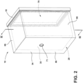
FIG. 2 is a side perspective view of an aspect of a vacuum insulated structure; -
FIG. 3 is an exploded side perspective view of a vacuum insulated structure for the appliance ofFIG. 2 ; -
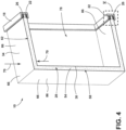
FIG. 4 is a cross-sectional view of the vacuum insulated structure ofFIG. 2 taken along the line IV-IV; -
FIG. 5 is a partial expanded view of a trim breaker and a barrier of the vacuum insulated structure ofFIG. 4 taken at area V; -
FIG. 6 is a schematic cross-sectional view of a trim breaker showing thin gas-blocking flakes set within a resin network along with various glass fiber and other silica-like material for creating the trim breaker; and -
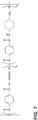
FIG. 7 is a chemical formula of one example of a resin employed in a trim breaker of the present disclosure. - The components in the figures are not necessarily to scale, emphasis instead being placed upon illustrating the principles described herein.
- The present illustrated embodiments reside primarily in combinations of method steps and apparatus components related to a vacuum insulated structure. Accordingly, the apparatus components and method steps have been represented, where appropriate, by conventional symbols in the drawings, showing only those specific details that are pertinent to understanding the embodiments of the present disclosure so as not to obscure the disclosure with details that will be readily apparent to those of ordinary skill in the art having the benefit of the description herein. Further, like numerals in the description and drawings represent like elements.
- For purposes of description herein, the terms "upper," "lower," "right," "left," "rear," "front," "vertical," "horizontal," and derivatives thereof shall relate to the disclosure as oriented in
FIG. 1 . Unless stated otherwise, the term "front" shall refer to the surface of the element closer to an intended viewer, and the term "rear" shall refer to the surface of the element further from the intended viewer. However, it is to be understood that the disclosure may assume various alternative orientations, except where expressly specified to the contrary. It is also to be understood that the specific devices and processes illustrated in the attached drawings, and described in the following specification are simply exemplary embodiments of the inventive concepts defined in the appended claims. Hence, specific dimensions and other physical characteristics relating to the embodiments disclosed herein are not to be considered as limiting, unless the claims expressly state otherwise. - The terms "including," "comprises," "comprising," or any other variation thereof, are intended to cover a non-exclusive inclusion, such that a process, method, article, or apparatus that comprises a list of elements does not include only those elements but may include other elements not expressly listed or inherent to such process, method, article, or apparatus. An element preceded by "comprises a ... " does not, without more constraints, preclude the existence of additional identical elements in the process, method, article, or apparatus that comprises the element.
- The terms "substantial," "substantially," and variations thereof as used herein are intended to note that a described feature is equal or approximately equal to a value or description. For example, a "substantially planar" surface is intended to denote a surface that is planar or approximately planar. Moreover, "substantially" is intended to denote that two values are equal or approximately equal. In some embodiments, "substantially" may denote values within about 10% of each other, such as within about 5% of each other, or within about 2% of each other.
- Referring to
FIGS. 1-7 ,reference numeral 10 generally designates an insulating structure for anappliance 14. Theinsulating structure 10 includes atrim breaker 18 that defines afirst groove 22 and asecond groove 26. Thefirst groove 22 and thesecond groove 26 are spaced from another defining acavity 28 therebetween. Afirst panel 30 is disposed within thefirst groove 22 and coupled to thetrim breaker 18. Asecond panel 34 is disposed within thesecond groove 26 and coupled to thetrim breaker 18. Anadhesive 38 is disposed within the first andsecond grooves second panels trim breaker 18 comprises a glycol-modified polyethyleneterephthalate copolyester resin 42. In some examples, thetrim breaker 18 has a heat deflection temperature of at least 100° Celsius. - Referring again to
FIGS. 1-4 , it is contemplated that theinsulating structure 10 may be in the form of a vacuum insulated structural cabinet or a vacuum insulated panel that may be used as an insulation member for theappliance 14. According to various examples, theinsulating structure 10 includes thefirst panel 30 and thesecond panel 34, which may alternatively be referred to as a liner and a wrapper, respectively. Hereinafter, thefirst panel 30 is referred to as theliner 30, and thesecond panel 34 is referred to as thewrapper 34. Thewrapper 34 and theliner 30, coupled to thetrim breaker 18, define theinsulating cavity 28 in which one ormore insulation materials 54 may be disposed. It is generally contemplated that theinsulation materials 54 are glass-type materials. However, it is also contemplated that theinsulation materials 54 may be a carbon-based powder, silicon oxide-based materials, insulating gasses, and otherstandard insulation materials 54 as known in the art; such materials are described more fully below. Theinsulation materials 54 substantially fill theinsulating cavity 28 forming a substantially continuous layer between theliner 30 and thewrapper 34. - In addition, an at least
partial vacuum 58 is defined within theinsulating cavity 28, where the at leastpartial vacuum 58 defines apressure differential 62 between anexterior 66 of theinsulating structure 10 and theinsulating cavity 28. Thispressure differential 62 serves to define an inwardcompressive force 70 that is exerted upon both thewrapper 34 and theliner 30 and tends to bias thewrapper 34 and theliner 30 toward theinsulating cavity 28 of theinsulating structure 10. The at leastpartial vacuum 58 within theinsulating cavity 28 also tends to cause gas to infiltrate into theinsulating cavity 28 from an area outside of theappliance 14. This infiltration of gas is sometimes referred to as gas permeation. - With continued reference to
FIGS. 1-4 , theinsulating structure 10 as described may be used in a variety of locations in theappliance 14. By way of example, not limitation, the glass structures, such as theglass trim breaker 18 or the adhesive 38 of theinsulating structure 10 may be used in conduits andaccess ports 71, for running electrical wiring, refrigeration, and water pipes, within the wall of theinsulating structure 10, amullion 72 of theappliance 14,door panels 73, and other parts of theappliance 14 in which it may be advantageous to resist gas permeation. - Referring now to
FIGS. 2-4 more particularly, as depicted in the form of a structural cabinet, thewrapper 34 has a three-dimensional shape such that a plurality of panels define acentral cavity 74. Correspondingly and as depicted, theliner 30 has a plurality of surfaces defining aninner cavity 78. It is generally contemplated that theliner 30 is received within thecentral cavity 74 of thewrapper 34, thus partially defining the insulatingcavity 28. Additionally, thewrapper 34 and theliner 30 includeinner surfaces 82 andouter surfaces 86 and may be made from a material at least partially resistant to bending, biasing, or otherwise being formed in response to the inwardcompressive force 70. These materials for theliner 30 and thewrapper 34 may include, but are not limited to, metals, polymers, metal alloys, combinations thereof, and other similar substantially rigid materials that can be used for vacuum insulated structures within appliances. It is contemplated that theliner 30 and thewrapper 34 may also be used to form a vacuum insulated panel. In such constructions, theliner 30 is referred to as the first panel, and thewrapper 34 is referred to as the second panel, as stated above. - Referring now to
FIG. 4 , it is contemplated that in addition to the first andsecond grooves trim breaker 18 may define athird groove 90. It is generally contemplated that thetrim breaker 18 defines at least one groove, which may include the first, second, andthird grooves second grooves liner 30 and thewrapper 34, respectively, to define the insulatingstructure 10. Additionally, thefirst groove 22 may alternatively be referred to as an inner groove, and thesecond groove 26 may be alternatively referred to as an outer groove. Further, thethird groove 90 may be referred to as a central groove. Hereinafter, the first, second, andthird grooves central grooves - In addition, the
trim breaker 18 has a receivingsurface 94 and asolid surface 96. It is generally contemplated that, along with thecentral groove 90, the inner andouter grooves surface 94 of thetrim breaker 18, such that theliner 30 and thewrapper 34 are received by the inner andouter grooves outer grooves liner 30 and thewrapper 34 to thetrim breaker 18. Moreover, the inner andouter grooves interior portions 100 that contact with and receive the adhesive 38 to secure theliner 30 and thewrapper 34 to thetrim breaker 18. Thecentral groove 90 may have a shallower depth than the inner andouter grooves - Referring now to
FIG. 6 , thetrim breaker 18 may be made of amixture 104 that includes a polyethyleneterephthalate copolyester resin 42. Themixture 104 may also include various flake-like particles. Such flake-like particles can include but are not limited to, mica, glass, other ceramic materials, combinations thereof, and other similar materials that can be made into fine flake-like particles or nanoflakes. In general, theflakes 108 may limit gas permeability through thetrim breaker 18. Anepoxy coating 112 may be disposed on an outer surface of thetrim breaker 18. Further, themixture 104 may include a plurality ofglass fibers 116. An exemplary polymer trim breaker having gas-blocking flakes and an epoxy coating is disclosed inU.S. Patent Application No. 16/520,572 , nowU.S. Patent No. 10,837,697 mixture 104 may be a homogenous mixture and that theresin 42 may comprise a polymer material and be molded to form thetrim breaker 18. In some examples, theflakes 108 and thefibers 116 are omitted and themixture 104 primarily employs theresin 42 to achieve the permeability rates described herein. - In general, the process of assembling the vacuum insulated
structure 10 may be limited in time by a curing time associated with the adhesive 38. In some examples, the curing time of the adhesive 38 is proportional to the temperature at which the adhesive 38 is applied in the first andsecond grooves trim breaker 18, longer curing times may result, and vice versa. Accordingly, to reduce assembly time for the vacuum insulatedstructure 10, the curing time may be reduced by increasing the temperature at which the adhesive 38 is applied. Although the first andsecond panels trim breaker 18 may have a corresponding heat deflection temperature that is less than a heat deflection temperature of the first andsecond panels second panels trim breaker 18. For example, the first andsecond panels trim breaker 18 may be a polymer or plastic having a lower heat deflection temperature than metal. In addition to deformation issues during an assembly of the vacuum insulated structure that may arise from plastics having low heat deflection temperatures, temperature fluctuation of an environment of theappliance 14 and/or the vacuum insulatedstructure 10 after assembly may also present heating conditions that exceed the heat deflection temperature of thetrim breaker 18 and may result in variations of a connection formed between thetrim breaker 18 and the first andsecond panels appliance 14 and/or the vacuum insulated structure, such as during storage of theappliance 14, shipping of theappliance 14, and the like, environmental conditions exceeding the heat deflection temperature of a trim breaker may be presented and expose the vacuum insulated structure to deformation. - The glycol modified polyethylene
terephthalate copolyester resin 42 of thetrim breaker 18 of the present disclosure may be incorporated to provide a high heat deflection temperature for thetrim breaker 18 to limit or eliminate such deflections. For example, thetrim breaker 18 of the present disclosure may have a heat deflection temperature that exceeds 67°C. In other examples, thetrim breaker 18 of the present disclosure may a have heat deflection temperature in the range of 72°C-100°C. In other examples, the heat deflection temperature of thepresent trim breaker 18 is at least 100°C. Because of the high heat deflection temperature of thetrim breaker 18, the adhesive 38, or the epoxy, may be applied at a temperature approximating the heat deflection temperature. For example, the adhesive 38 may be applied at a temperature that approaches 100°C without resulting in deflection of thetrim breaker 18. Accordingly, an assembly time for the vacuum insulated structure may be reduced significantly from in the range of two hours or more to 30 minutes or less by reducing the curing time of the adhesive 38 in the first andsecond grooves resin 42 may also provide for acceptable and/or reduced permeation rates of nitrogen, oxygen, water vapor, and other gases. - Referring now to
FIG. 7 , one unit example of the chemical makeup of a glycol modified polyethyleneterephthalate copolyester resin 42 material employed with thetrim breaker 18 includes a polyester bonded with another terephthalate-alcohol group. It is contemplated that other functional groups may also be included to alter properties of theresin 42. It is further contemplated that the chemical structure sown inFIG. 7 is non-limiting, and that various alcohol-modified polyethylene terephthalate materials may be employed. - In some examples, the
trim breaker 18 is substantially impermeable to gases and/or liquids. In some examples, a permeation rate for oxygen through thetrim breaker 18 is less than 2.5 cc.mm/m2/day/atm. In some examples, the permeation rate for oxygen through thetrim breaker 18 is between 1 and 20 cc.mm/m2/day/atm. In some examples, a permeation rate for nitrogen through thetrim breaker 18 is less than 2 cc.mm/m2/day/atm. In some examples, the permeation rate for nitrogen is between 0.05 and 1.2 cc.mm/m2/day/atm. In some examples, a permeation rate for water vapor transmission is less than 25 cc.mm/m2/day/atm. In some examples, the permeation rate for water vapor transmission is between 0.07 and 1.8 cc.mm/m2/day/atm. In general, the permeation rates described above are at 1 atmosphere and at room temperature. In some examples, the above rates are determined based on permeation from an interior of the vacuum-insulatedstructure 10 toward an exterior of thevacuum insulating structure 10, and such rates maybe determined along a longitudinal along a longitudinal axis of the trim breaker (e.g., in a direction parallel with the first andsecond panels 30, 34). - It is contemplated that the ranges described above may be achieved via the inclusion of the glycol modified polyethylene terephthalate polyester alone or in combination with the mica flakes or glass flakes described above. For example, doping of the
flakes 108 with theresin 42 may be employed to achieve the permeation rates, while the heating characteristics (e.g., a high heat deflection temperature (HDT)) of thetrim breaker 18 may be a result of the inclusion of the particular type ofcopolyester resin 42 employed in the present disclosure. In some examples, the doping may include injecting theflakes 108 into theresin 42 at high temperature and/or pressure via solid-state diffusion techniques. The result may present a heterogenous orhomogenous mixture 104. - According to the various examples, the insulating
structure 10 can be used in various appliances that can include but are not limited to, refrigerators, freezers, coolers, ovens, dishwashers, laundry appliances, water heaters, and other similar appliances and fixtures within household and commercial settings. Additionally, theinsulation materials 54 can be a free-flowing material that can be poured, blown, compacted or otherwise disposed within the insulatingcavity 28. This free-flowing material can be in the form of various silica-based materials, such as fumed silica, precipitated silica, nano-sized and/or micro-sided aerogel powder, rice husk ash powder, perlite, glass spheres, hollow glass spheres, cenospheres, diatomaceous earth, combinations thereof, and other similar insulating particulate material. - The invention disclosed herein is further summarized in the following paragraphs, and is further characterized by combinations of any and all of the various aspects described herein.
- According to one aspect of the present disclosure, a vacuum insulated structure for an appliance includes a trim breaker defining a first groove and a second groove. A first panel is disposed within the first groove and coupled to the trim breaker. A second panel is disposed within the second groove and coupled to the trim breaker. An adhesive is disposed within the first and second grooves and coupled to the first and second panels, respectively, wherein the trim breaker has a heat deflection temperature of at least 100° Celsius.
- According to another aspect of the present disclosure, the trim breaker comprises a glycol-modified polyethylene terephthalate copolyester.
- According to another aspect of the present disclosure, the trim breaker comprises mica flakes doped in the glycol-modified polyethylene terephthalate copolyester.
- According to another aspect of the present disclosure, the trim breaker has a nitrogen transmission rate of less than 2 cc.mm/m2/day/atm.
- According to another aspect of the present disclosure, the nitrogen transmission rate is between 0.05 and 1.2 cc.mm/m2/day/atm.
- According to another aspect of the present disclosure, the trim breaker has a water vapor transmission rate of less than 25 cc.mm/m2/day/atm.
- According to another aspect of the present disclosure, the water vapor transmission rate is between 0.07 and 1.8 cc.mm/m2/day/atm.
- According to another aspect of the present disclosure, the trim breaker has an oxygen transmission rate of less than 2.5 cc.mm/m2/day/atm.
- According to another aspect of the present disclosure, the trim breaker has an oxygen transmission rate of between 1 and 20 cc.mm/m2/day/atm.
- According to another aspect of the present disclosure, a vacuum insulated structure for a refrigerator includes a trim breaker that defines a first groove and a second groove spaced from one another defining a cavity therebetween. A first panel is disposed within the first groove and coupled to the trim breaker. A second panel is disposed within the second groove and coupled to the trim breaker. An adhesive is disposed within the first and second grooves and coupled to the first and second panels, respectively. The trim breaker includes a polyethylene terephthalate copolyester resin and has a water vapor transmission rate of less than 25 cc.mm/m2/day/atm.
- According to another aspect of the present disclosure, the polyethylene terephthalate copolyester resin includes glycol.
- According to another aspect of the present disclosure, the trim breaker has a heat deflection temperature of at least 100° Celsius.
- According to another aspect of the present disclosure, the trim breaker has a nitrogen transmission rate of less than 2 cc.mm/m2/day/atm.
- According to another aspect of the present disclosure, the nitrogen transmission rate is between 0.05 and 1.2 cc.mm/m2/day/atm.
- According to another aspect of the present disclosure, the water vapor transmission rate is between 0.07 and 1.8 cc.mm/m2/day/atm.
- According to another aspect of the present disclosure, the trim breaker has an oxygen transmission rate of less than 2.5 cc.mm/m2/day/atm.
- According to another aspect of the present disclosure, the trim breaker has an oxygen transmission rate of between 1 and 20 cc.mm/m2/day/atm.
- According to another aspect of the present disclosure, a vacuum insulated panel for a refrigerator includes a trim breaker that defines a first groove and a second groove spaced from one another defining a cavity therebetween. A liner is disposed in the first groove and coupled to the trim breaker. A wrapper is disposed in the second groove and coupled to the trim breaker. An adhesive is disposed within the first and second grooves and coupled to the first and second panels, respectively. The trim breaker comprises a glycol-modified polyethylene terephthalate copolyester resin and has a heat deflection temperature of at least 100° Celsius.
- According to another aspect of the present disclosure, the trim breaker comprises mica flakes doped in the glycol-modified polyethylene terephthalate copolyester resin.
- According to another aspect of the present disclosure, the trim breaker has a water vapor transmission rate of less than 25 cc.mm/m2/day/atm.
- It will be understood by one having ordinary skill in the art that construction of the described disclosure and other components is not limited to any specific material. Other exemplary embodiments of the disclosure disclosed herein may be formed from a wide variety of materials, unless described otherwise herein.
- For purposes of this disclosure, the term "coupled" (in all of its forms, couple, coupling, coupled, etc.) generally means the joining of two components (electrical or mechanical) directly or indirectly to one another. Such joining may be stationary in nature or movable in nature. Such joining may be achieved with the two components (electrical or mechanical) and any additional intermediate members being integrally formed as a single unitary body with one another or with the two components. Such joining may be permanent in nature or may be removable or releasable in nature unless otherwise stated.
- It is also important to note that the construction and arrangement of the elements of the disclosure as shown in the exemplary embodiments is illustrative only. Although only a few embodiments of the present innovations have been described in detail in this disclosure, those skilled in the art who review this disclosure will readily appreciate that many modifications are possible (e.g., variations in sizes, dimensions, structures, shapes, and proportions of the various elements, values of parameters, mounting arrangements, use of materials, colors, orientations, etc.) without materially departing from the novel teachings and advantages of the subject matter recited. For example, elements shown as integrally formed may be constructed of multiple parts or elements shown as multiple parts may be integrally formed, the operation of the interfaces may be reversed or otherwise varied, the length or width of the structures and/or members or connector or other elements of the system may be varied, the nature or number of adjustment positions provided between the elements may be varied. It should be noted that the elements and/or assemblies of the system may be constructed from any of a wide variety of materials that provide sufficient strength or durability, in any of a wide variety of colors, textures, and combinations. Accordingly, all such modifications are intended to be included within the scope of the present innovations. Other substitutions, modifications, changes, and omissions may be made in the design, operating conditions, and arrangement of the desired and other exemplary embodiments without departing from the spirit of the present innovations.
- It will be understood that any described processes or steps within described processes may be combined with other disclosed processes or steps to form structures within the scope of the present disclosure. The exemplary structures and processes disclosed herein are for illustrative purposes and are not to be construed as limiting.
Claims (15)
- A vacuum insulated structure (10) for an appliance (14), comprising:a trim breaker (18) defining a first groove (22) and a second groove (26);a first panel (30) disposed within the first groove (22) and coupled to the trim breaker (18);a second panel (34) disposed within the second groove (26) and coupled to the trim breaker (18); andan adhesive (38) disposed within the first groove (22) and within the second groove (26) and coupled to the first panel (30) and to the second panel (34), respectively,characterised in that the trim breaker (18) comprises a polyethylene terephthalate copolyester resin.
- The vacuum insulated structure (10) of claim 1, wherein the first groove (22) and the second groove (26) are spaced from one another to define a cavity (28) therebetween and/or wherein the first groove (22), the second groove (26) and the trim breaker (18) define together a cavity (28), in particular wherein insulation materials (54) fill the cavity (28) forming a substantially continuous layer between the first panel (30) and the second panel (34).
- The vacuum insulated structure (10) of claim 1 or claim 2, wherein the polyethylene terephthalate copolyester resin is a glycol-modified polyethylene terephthalate copolyester resin and/or wherein the polyethylene terephthalate copolyester resin includes glycol.
- The vacuum insulated structure (10) of any one of claims 1 to 3, wherein the trim breaker (18) has a heat deflection temperature of at least 100° Celsius.
- The vacuum insulated structure (10) of any one of claims 1 to 4, wherein the trim breaker (18) has a nitrogen transmission rate of less than 2 cc.mm/m2/day/atm, in particular wherein the nitrogen transmission rate is between 0.05 and 1.2 cc.mm/m2/day/atm.
- The vacuum insulated structure (10) of any one of claims 1 to 5, wherein the trim breaker (18) has a water vapor transmission rate of less than 25 cc.mm/m2/day/atm, in particular wherein the water vapor transmission rate is less than 20 cc.mm/m2/day/atm, more in particular wherein the water vapor transmission rate is between 0.07 and 1.8 cc.mm/m2/day/atm.
- The vacuum insulated structure (10) of any one of claims 1 to 6, wherein the trim breaker has an oxygen transmission rate of less than 20 cc.mm/m2/day/atm, in particular wherein the oxygen transmission rate is less than 2.5 cc.mm/m2/day/atm, more in particular wherein the trim breaker has an oxygen transmission rate of between 1 and 2.5 cc.mm/m2/day/atm.
- The vacuum insulated structure (10) of any one of claims 1 to 7, wherein the trim breaker (18) comprises flakes (108), in particular mica flakes or glass flakes or ceramic flakes, doped in the polyethylene terephthalate copolyester, in particular in the glycol-modified polyethylene terephthalate copolyester.
- The vacuum insulated structure (10) of any one of claims 1 to 8, wherein the trim breaker (18) comprises fibers (116), in particular glass fibers or fibers made of silica-like material.
- The vacuum insulated structure (10) of any one of claims 1 to 9, wherein an epoxy coating (112) is disposed on a surface of the trim breaker (18), in particular on an outer surface of the trim breaker (18).
- The vacuum insulated structure (10) of any one of claims 1 to 10, wherein the trim breaker (18) further defines a third groove (90), the third groove (90) being centrally arranged between the first groove (22) and the second groove (26), in particular wherein the third groove (90) has a shallower depth than the first groove (22) and the second groove (26).
- The vacuum insulated structure (10) of any one of claims 1 to 11, wherein the adhesive (38) is cured in the first groove (22) and in the second groove (26) and wherein the vacuum insulated structure (10) is assembled in a time of 30 minutes or less.
- A refrigerator comprising the vacuum insulated structure (10) of any one of claims 1 to 12, wherein the first panel (30) is a liner, in particular a plastic liner or a metal liner, and wherein the second panel (34) is a wrapper, in particular a plastic wrapper or a metal wrapper.
- The refrigerator of claim 13, wherein the vacuum insulated structure (10) forms a part of a door of the refrigerator.
- The refrigerator of claim 13 or claim 14, wherein the vacuum insulated structure (10) forms a part of a cabinet of the refrigerator.
Priority Applications (1)
| Application Number | Priority Date | Filing Date | Title |
|---|---|---|---|
| EP24218623.7A EP4517231A3 (en) | 2022-08-05 | 2023-07-19 | Vacuum insulated structure including a trim breaker |
Applications Claiming Priority (1)
| Application Number | Priority Date | Filing Date | Title |
|---|---|---|---|
| US17/881,788 US20240044571A1 (en) | 2022-08-05 | 2022-08-05 | Vacuum insulated structure |
Related Child Applications (2)
| Application Number | Title | Priority Date | Filing Date |
|---|---|---|---|
| EP24218623.7A Division EP4517231A3 (en) | 2022-08-05 | 2023-07-19 | Vacuum insulated structure including a trim breaker |
| EP24218623.7A Division-Into EP4517231A3 (en) | 2022-08-05 | 2023-07-19 | Vacuum insulated structure including a trim breaker |
Publications (2)
| Publication Number | Publication Date |
|---|---|
| EP4316768A1 true EP4316768A1 (en) | 2024-02-07 |
| EP4316768B1 EP4316768B1 (en) | 2025-01-15 |
Family
ID=87426565
Family Applications (2)
| Application Number | Title | Priority Date | Filing Date |
|---|---|---|---|
| EP23186488.5A Active EP4316768B1 (en) | 2022-08-05 | 2023-07-19 | Vacuum insulated structure |
| EP24218623.7A Pending EP4517231A3 (en) | 2022-08-05 | 2023-07-19 | Vacuum insulated structure including a trim breaker |
Family Applications After (1)
| Application Number | Title | Priority Date | Filing Date |
|---|---|---|---|
| EP24218623.7A Pending EP4517231A3 (en) | 2022-08-05 | 2023-07-19 | Vacuum insulated structure including a trim breaker |
Country Status (2)
| Country | Link |
|---|---|
| US (1) | US20240044571A1 (en) |
| EP (2) | EP4316768B1 (en) |
Citations (9)
| Publication number | Priority date | Publication date | Assignee | Title |
|---|---|---|---|---|
| US20030157284A1 (en) * | 2000-04-21 | 2003-08-21 | Yasuaki Tanimoto | Vacuum insulating material and device using the same |
| WO2010007706A1 (en) * | 2008-07-17 | 2010-01-21 | 日立アプライアンス株式会社 | Vacuum heat insulating material |
| KR101017776B1 (en) * | 2007-09-06 | 2011-02-28 | 히타치 어플라이언스 가부시키가이샤 | Vacuum Insulation and Refrigerator Using Them |
| EP2463605A2 (en) * | 2010-12-09 | 2012-06-13 | BSH Bosch und Siemens Hausgeräte GmbH | Housing components for a cooler |
| KR20130010815A (en) * | 2011-07-19 | 2013-01-29 | 히타치 어플라이언스 가부시키가이샤 | Refrigerator |
| US20150044412A1 (en) * | 2012-03-23 | 2015-02-12 | Panasonic Corporation | Vacuum insulation material and heat insulation housing using the same |
| US10837697B2 (en) | 2018-10-31 | 2020-11-17 | Whirlpool Corporation | Polymer trim breaker having gas-blocking flakes and an epoxy coating |
| US20200406527A1 (en) * | 2015-12-29 | 2020-12-31 | Whirlpool Corporation | Molded gas barrier parts for vacuum insulated structure |
| US20210199860A1 (en) * | 2018-01-29 | 2021-07-01 | Daicel Corporation | Molded article and method for manufacturing molded article |
Family Cites Families (12)
| Publication number | Priority date | Publication date | Assignee | Title |
|---|---|---|---|---|
| US7923506B2 (en) * | 2006-01-27 | 2011-04-12 | Sabic Innovative Plastics Ip B.V. | Molding compositions containing modified polybutylene terephthalate (PBT) random copolymers derived from polyethylene terephthalate (PET) |
| US20120246873A1 (en) * | 2011-04-01 | 2012-10-04 | Rama Konduri | Hollow articles comprising fiber-filled polyester compositions, methods of manufacture, and uses thereof |
| JP2014144584A (en) * | 2013-01-29 | 2014-08-14 | Mitsubishi Gas Chemical Co Inc | Method for preserving dried article |
| US20160258671A1 (en) * | 2015-03-02 | 2016-09-08 | Whirlpool Corporation | Gas barrier for vacuum insulation |
| US10830526B2 (en) * | 2016-09-26 | 2020-11-10 | Whirlpool Corporation | Vacuum generating system for an appliance incorporating a vacuum insulated structure |
| EP3519746B1 (en) * | 2016-10-03 | 2022-10-26 | Whirlpool Corporation | Encapsulation system for a thermal bridge breaker-to-metal liner |
| WO2018151705A1 (en) * | 2017-02-14 | 2018-08-23 | Whirlpool Corporation | Multi-layer encapsulation system for joint sealing of vacuum insulated cabinets |
| US10697699B2 (en) * | 2018-11-05 | 2020-06-30 | Whirlpool Corporation | Cabinet assembly of an appliance |
| US11346596B2 (en) * | 2019-12-30 | 2022-05-31 | Whirpool Corporation | Trim breaker for an insulated appliance |
| US10914514B1 (en) * | 2020-01-17 | 2021-02-09 | Whirlpool Corporation | Illuminated trim assembly for appliance |
| US11624547B2 (en) * | 2021-06-14 | 2023-04-11 | Whirlpool Corporation | Bin attachment assembly for a trim breaker |
| US12460457B2 (en) * | 2021-09-10 | 2025-11-04 | Andersen Corporation | Sash tilt bolt and checkrail bracket systems for coastal impact resistant fenestrations |
-
2022
- 2022-08-05 US US17/881,788 patent/US20240044571A1/en not_active Abandoned
-
2023
- 2023-07-19 EP EP23186488.5A patent/EP4316768B1/en active Active
- 2023-07-19 EP EP24218623.7A patent/EP4517231A3/en active Pending
Patent Citations (9)
| Publication number | Priority date | Publication date | Assignee | Title |
|---|---|---|---|---|
| US20030157284A1 (en) * | 2000-04-21 | 2003-08-21 | Yasuaki Tanimoto | Vacuum insulating material and device using the same |
| KR101017776B1 (en) * | 2007-09-06 | 2011-02-28 | 히타치 어플라이언스 가부시키가이샤 | Vacuum Insulation and Refrigerator Using Them |
| WO2010007706A1 (en) * | 2008-07-17 | 2010-01-21 | 日立アプライアンス株式会社 | Vacuum heat insulating material |
| EP2463605A2 (en) * | 2010-12-09 | 2012-06-13 | BSH Bosch und Siemens Hausgeräte GmbH | Housing components for a cooler |
| KR20130010815A (en) * | 2011-07-19 | 2013-01-29 | 히타치 어플라이언스 가부시키가이샤 | Refrigerator |
| US20150044412A1 (en) * | 2012-03-23 | 2015-02-12 | Panasonic Corporation | Vacuum insulation material and heat insulation housing using the same |
| US20200406527A1 (en) * | 2015-12-29 | 2020-12-31 | Whirlpool Corporation | Molded gas barrier parts for vacuum insulated structure |
| US20210199860A1 (en) * | 2018-01-29 | 2021-07-01 | Daicel Corporation | Molded article and method for manufacturing molded article |
| US10837697B2 (en) | 2018-10-31 | 2020-11-17 | Whirlpool Corporation | Polymer trim breaker having gas-blocking flakes and an epoxy coating |
Also Published As
| Publication number | Publication date |
|---|---|
| US20240044571A1 (en) | 2024-02-08 |
| EP4517231A2 (en) | 2025-03-05 |
| EP4316768B1 (en) | 2025-01-15 |
| EP4517231A3 (en) | 2025-04-30 |
Similar Documents
| Publication | Publication Date | Title |
|---|---|---|
| US20240167758A1 (en) | Vacuum insulated structure | |
| EP3387351B1 (en) | Vacuum insulation structures with multiple insulators | |
| US11692763B2 (en) | Insulation materials for a vacuum insulated structure and methods of forming | |
| US12049784B2 (en) | Insulated door assembly | |
| US12031771B2 (en) | Barrier layer for insulated structures | |
| EP3615872B1 (en) | Structural cabinet for an appliance | |
| US20230010720A1 (en) | Machine compartment for a vacuum insulated structure | |
| WO2018022007A1 (en) | Vacuum insulated structure trim breaker | |
| US20210207878A1 (en) | Vacuum insulated structure with thermal bridge breaker with heat loop | |
| CN111578571A (en) | Decorative partition for structural cabinets comprising a structural glass contact surface | |
| KR101560125B1 (en) | Method for manufacturing insulation box improved insulation performance and insulation box for the same | |
| EP4316768B1 (en) | Vacuum insulated structure | |
| KR20200001375A (en) | Vacuum adiabatic body and refrigerator | |
| US20240271859A1 (en) | Vacuum insulated structure with thermal bridge breaker with heat loop | |
| CN120027567A (en) | Decorative divider step cover | |
| JPH11199347A (en) | Thin hollow body and heat insulating material using the same |
Legal Events
| Date | Code | Title | Description |
|---|---|---|---|
| PUAI | Public reference made under article 153(3) epc to a published international application that has entered the european phase |
Free format text: ORIGINAL CODE: 0009012 |
|
| STAA | Information on the status of an ep patent application or granted ep patent |
Free format text: STATUS: THE APPLICATION HAS BEEN PUBLISHED |
|
| AK | Designated contracting states |
Kind code of ref document: A1 Designated state(s): AL AT BE BG CH CY CZ DE DK EE ES FI FR GB GR HR HU IE IS IT LI LT LU LV MC ME MK MT NL NO PL PT RO RS SE SI SK SM TR |
|
| STAA | Information on the status of an ep patent application or granted ep patent |
Free format text: STATUS: REQUEST FOR EXAMINATION WAS MADE |
|
| P01 | Opt-out of the competence of the unified patent court (upc) registered |
Effective date: 20240228 |
|
| 17P | Request for examination filed |
Effective date: 20240311 |
|
| RBV | Designated contracting states (corrected) |
Designated state(s): AL AT BE BG CH CY CZ DE DK EE ES FI FR GB GR HR HU IE IS IT LI LT LU LV MC ME MK MT NL NO PL PT RO RS SE SI SK SM TR |
|
| GRAP | Despatch of communication of intention to grant a patent |
Free format text: ORIGINAL CODE: EPIDOSNIGR1 |
|
| STAA | Information on the status of an ep patent application or granted ep patent |
Free format text: STATUS: GRANT OF PATENT IS INTENDED |
|
| INTG | Intention to grant announced |
Effective date: 20240705 |
|
| GRAS | Grant fee paid |
Free format text: ORIGINAL CODE: EPIDOSNIGR3 |
|
| GRAA | (expected) grant |
Free format text: ORIGINAL CODE: 0009210 |
|
| STAA | Information on the status of an ep patent application or granted ep patent |
Free format text: STATUS: THE PATENT HAS BEEN GRANTED |
|
| AK | Designated contracting states |
Kind code of ref document: B1 Designated state(s): AL AT BE BG CH CY CZ DE DK EE ES FI FR GB GR HR HU IE IS IT LI LT LU LV MC ME MK MT NL NO PL PT RO RS SE SI SK SM TR |
|
| REG | Reference to a national code |
Ref country code: CH Ref legal event code: EP Ref country code: GB Ref legal event code: FG4D |
|
| REG | Reference to a national code |
Ref country code: DE Ref legal event code: R096 Ref document number: 602023001670 Country of ref document: DE |
|
| REG | Reference to a national code |
Ref country code: IE Ref legal event code: FG4D |
|
| REG | Reference to a national code |
Ref country code: NL Ref legal event code: MP Effective date: 20250115 |
|
| PG25 | Lapsed in a contracting state [announced via postgrant information from national office to epo] |
Ref country code: NL Free format text: LAPSE BECAUSE OF FAILURE TO SUBMIT A TRANSLATION OF THE DESCRIPTION OR TO PAY THE FEE WITHIN THE PRESCRIBED TIME-LIMIT Effective date: 20250115 |
|
| PG25 | Lapsed in a contracting state [announced via postgrant information from national office to epo] |
Ref country code: RS Free format text: LAPSE BECAUSE OF FAILURE TO SUBMIT A TRANSLATION OF THE DESCRIPTION OR TO PAY THE FEE WITHIN THE PRESCRIBED TIME-LIMIT Effective date: 20250415 |
|
| PG25 | Lapsed in a contracting state [announced via postgrant information from national office to epo] |
Ref country code: FI Free format text: LAPSE BECAUSE OF FAILURE TO SUBMIT A TRANSLATION OF THE DESCRIPTION OR TO PAY THE FEE WITHIN THE PRESCRIBED TIME-LIMIT Effective date: 20250115 |
|
| PG25 | Lapsed in a contracting state [announced via postgrant information from national office to epo] |
Ref country code: PL Free format text: LAPSE BECAUSE OF FAILURE TO SUBMIT A TRANSLATION OF THE DESCRIPTION OR TO PAY THE FEE WITHIN THE PRESCRIBED TIME-LIMIT Effective date: 20250115 |
|
| PG25 | Lapsed in a contracting state [announced via postgrant information from national office to epo] |
Ref country code: ES Free format text: LAPSE BECAUSE OF FAILURE TO SUBMIT A TRANSLATION OF THE DESCRIPTION OR TO PAY THE FEE WITHIN THE PRESCRIBED TIME-LIMIT Effective date: 20250115 |
|
| REG | Reference to a national code |
Ref country code: LT Ref legal event code: MG9D |
|
| PG25 | Lapsed in a contracting state [announced via postgrant information from national office to epo] |
Ref country code: NO Free format text: LAPSE BECAUSE OF FAILURE TO SUBMIT A TRANSLATION OF THE DESCRIPTION OR TO PAY THE FEE WITHIN THE PRESCRIBED TIME-LIMIT Effective date: 20250415 Ref country code: IS Free format text: LAPSE BECAUSE OF FAILURE TO SUBMIT A TRANSLATION OF THE DESCRIPTION OR TO PAY THE FEE WITHIN THE PRESCRIBED TIME-LIMIT Effective date: 20250515 |
|
| REG | Reference to a national code |
Ref country code: AT Ref legal event code: MK05 Ref document number: 1759572 Country of ref document: AT Kind code of ref document: T Effective date: 20250115 |
|
| PG25 | Lapsed in a contracting state [announced via postgrant information from national office to epo] |
Ref country code: HR Free format text: LAPSE BECAUSE OF FAILURE TO SUBMIT A TRANSLATION OF THE DESCRIPTION OR TO PAY THE FEE WITHIN THE PRESCRIBED TIME-LIMIT Effective date: 20250115 |
|
| PG25 | Lapsed in a contracting state [announced via postgrant information from national office to epo] |
Ref country code: LV Free format text: LAPSE BECAUSE OF FAILURE TO SUBMIT A TRANSLATION OF THE DESCRIPTION OR TO PAY THE FEE WITHIN THE PRESCRIBED TIME-LIMIT Effective date: 20250115 Ref country code: PT Free format text: LAPSE BECAUSE OF FAILURE TO SUBMIT A TRANSLATION OF THE DESCRIPTION OR TO PAY THE FEE WITHIN THE PRESCRIBED TIME-LIMIT Effective date: 20250515 |
|
| PG25 | Lapsed in a contracting state [announced via postgrant information from national office to epo] |
Ref country code: GR Free format text: LAPSE BECAUSE OF FAILURE TO SUBMIT A TRANSLATION OF THE DESCRIPTION OR TO PAY THE FEE WITHIN THE PRESCRIBED TIME-LIMIT Effective date: 20250416 Ref country code: BG Free format text: LAPSE BECAUSE OF FAILURE TO SUBMIT A TRANSLATION OF THE DESCRIPTION OR TO PAY THE FEE WITHIN THE PRESCRIBED TIME-LIMIT Effective date: 20250115 |
|
| PG25 | Lapsed in a contracting state [announced via postgrant information from national office to epo] |
Ref country code: AT Free format text: LAPSE BECAUSE OF FAILURE TO SUBMIT A TRANSLATION OF THE DESCRIPTION OR TO PAY THE FEE WITHIN THE PRESCRIBED TIME-LIMIT Effective date: 20250115 |
|
| PG25 | Lapsed in a contracting state [announced via postgrant information from national office to epo] |
Ref country code: SE Free format text: LAPSE BECAUSE OF FAILURE TO SUBMIT A TRANSLATION OF THE DESCRIPTION OR TO PAY THE FEE WITHIN THE PRESCRIBED TIME-LIMIT Effective date: 20250115 |
|
| PG25 | Lapsed in a contracting state [announced via postgrant information from national office to epo] |
Ref country code: SM Free format text: LAPSE BECAUSE OF FAILURE TO SUBMIT A TRANSLATION OF THE DESCRIPTION OR TO PAY THE FEE WITHIN THE PRESCRIBED TIME-LIMIT Effective date: 20250115 |
|
| PG25 | Lapsed in a contracting state [announced via postgrant information from national office to epo] |
Ref country code: DK Free format text: LAPSE BECAUSE OF FAILURE TO SUBMIT A TRANSLATION OF THE DESCRIPTION OR TO PAY THE FEE WITHIN THE PRESCRIBED TIME-LIMIT Effective date: 20250115 |
|
| PGFP | Annual fee paid to national office [announced via postgrant information from national office to epo] |
Ref country code: DE Payment date: 20250728 Year of fee payment: 3 |
|
| PG25 | Lapsed in a contracting state [announced via postgrant information from national office to epo] |
Ref country code: IT Free format text: LAPSE BECAUSE OF FAILURE TO SUBMIT A TRANSLATION OF THE DESCRIPTION OR TO PAY THE FEE WITHIN THE PRESCRIBED TIME-LIMIT Effective date: 20250115 |
|
| REG | Reference to a national code |
Ref country code: DE Ref legal event code: R097 Ref document number: 602023001670 Country of ref document: DE |
|
| PG25 | Lapsed in a contracting state [announced via postgrant information from national office to epo] |
Ref country code: EE Free format text: LAPSE BECAUSE OF FAILURE TO SUBMIT A TRANSLATION OF THE DESCRIPTION OR TO PAY THE FEE WITHIN THE PRESCRIBED TIME-LIMIT Effective date: 20250115 Ref country code: CZ Free format text: LAPSE BECAUSE OF FAILURE TO SUBMIT A TRANSLATION OF THE DESCRIPTION OR TO PAY THE FEE WITHIN THE PRESCRIBED TIME-LIMIT Effective date: 20250115 |
|
| PG25 | Lapsed in a contracting state [announced via postgrant information from national office to epo] |
Ref country code: RO Free format text: LAPSE BECAUSE OF FAILURE TO SUBMIT A TRANSLATION OF THE DESCRIPTION OR TO PAY THE FEE WITHIN THE PRESCRIBED TIME-LIMIT Effective date: 20250115 |
|
| PG25 | Lapsed in a contracting state [announced via postgrant information from national office to epo] |
Ref country code: SK Free format text: LAPSE BECAUSE OF FAILURE TO SUBMIT A TRANSLATION OF THE DESCRIPTION OR TO PAY THE FEE WITHIN THE PRESCRIBED TIME-LIMIT Effective date: 20250115 |
|
| PLBE | No opposition filed within time limit |
Free format text: ORIGINAL CODE: 0009261 |
|
| STAA | Information on the status of an ep patent application or granted ep patent |
Free format text: STATUS: NO OPPOSITION FILED WITHIN TIME LIMIT |
|
| 26N | No opposition filed |
Effective date: 20251016 |
|
| PG25 | Lapsed in a contracting state [announced via postgrant information from national office to epo] |
Ref country code: LU Free format text: LAPSE BECAUSE OF NON-PAYMENT OF DUE FEES Effective date: 20250719 |
|
| REG | Reference to a national code |
Ref country code: BE Ref legal event code: MM Effective date: 20250731 |
|
| PG25 | Lapsed in a contracting state [announced via postgrant information from national office to epo] |
Ref country code: BE Free format text: LAPSE BECAUSE OF NON-PAYMENT OF DUE FEES Effective date: 20250731 |
|
| PG25 | Lapsed in a contracting state [announced via postgrant information from national office to epo] |
Ref country code: FR Free format text: LAPSE BECAUSE OF NON-PAYMENT OF DUE FEES Effective date: 20250731 |