EP4316767A1 - Device for manufacturing fiber-reinforced resin, and method for manufacturing fiber-reinforced resin - Google Patents
Device for manufacturing fiber-reinforced resin, and method for manufacturing fiber-reinforced resin Download PDFInfo
- Publication number
- EP4316767A1 EP4316767A1 EP22775240.9A EP22775240A EP4316767A1 EP 4316767 A1 EP4316767 A1 EP 4316767A1 EP 22775240 A EP22775240 A EP 22775240A EP 4316767 A1 EP4316767 A1 EP 4316767A1
- Authority
- EP
- European Patent Office
- Prior art keywords
- reinforcing fibers
- fiber
- resin
- section
- reinforcing
- Prior art date
- Legal status (The legal status is an assumption and is not a legal conclusion. Google has not performed a legal analysis and makes no representation as to the accuracy of the status listed.)
- Pending
Links
Images




Classifications
-
- B—PERFORMING OPERATIONS; TRANSPORTING
- B29—WORKING OF PLASTICS; WORKING OF SUBSTANCES IN A PLASTIC STATE IN GENERAL
- B29C—SHAPING OR JOINING OF PLASTICS; SHAPING OF MATERIAL IN A PLASTIC STATE, NOT OTHERWISE PROVIDED FOR; AFTER-TREATMENT OF THE SHAPED PRODUCTS, e.g. REPAIRING
- B29C70/00—Shaping composites, i.e. plastics material comprising reinforcements, fillers or preformed parts, e.g. inserts
- B29C70/04—Shaping composites, i.e. plastics material comprising reinforcements, fillers or preformed parts, e.g. inserts comprising reinforcements only, e.g. self-reinforcing plastics
- B29C70/06—Fibrous reinforcements only
- B29C70/10—Fibrous reinforcements only characterised by the structure of fibrous reinforcements, e.g. hollow fibres
- B29C70/16—Fibrous reinforcements only characterised by the structure of fibrous reinforcements, e.g. hollow fibres using fibres of substantial or continuous length
- B29C70/20—Fibrous reinforcements only characterised by the structure of fibrous reinforcements, e.g. hollow fibres using fibres of substantial or continuous length oriented in a single direction, e.g. roofing or other parallel fibres
-
- B—PERFORMING OPERATIONS; TRANSPORTING
- B29—WORKING OF PLASTICS; WORKING OF SUBSTANCES IN A PLASTIC STATE IN GENERAL
- B29B—PREPARATION OR PRETREATMENT OF THE MATERIAL TO BE SHAPED; MAKING GRANULES OR PREFORMS; RECOVERY OF PLASTICS OR OTHER CONSTITUENTS OF WASTE MATERIAL CONTAINING PLASTICS
- B29B15/00—Pretreatment of the material to be shaped, not covered by groups B29B7/00 - B29B13/00
- B29B15/08—Pretreatment of the material to be shaped, not covered by groups B29B7/00 - B29B13/00 of reinforcements or fillers
- B29B15/10—Coating or impregnating independently of the moulding or shaping step
- B29B15/12—Coating or impregnating independently of the moulding or shaping step of reinforcements of indefinite length
- B29B15/122—Coating or impregnating independently of the moulding or shaping step of reinforcements of indefinite length with a matrix in liquid form, e.g. as melt, solution or latex
-
- B—PERFORMING OPERATIONS; TRANSPORTING
- B29—WORKING OF PLASTICS; WORKING OF SUBSTANCES IN A PLASTIC STATE IN GENERAL
- B29C—SHAPING OR JOINING OF PLASTICS; SHAPING OF MATERIAL IN A PLASTIC STATE, NOT OTHERWISE PROVIDED FOR; AFTER-TREATMENT OF THE SHAPED PRODUCTS, e.g. REPAIRING
- B29C65/00—Joining or sealing of preformed parts, e.g. welding of plastics materials; Apparatus therefor
- B29C65/48—Joining or sealing of preformed parts, e.g. welding of plastics materials; Apparatus therefor using adhesives, i.e. using supplementary joining material; solvent bonding
- B29C65/50—Joining or sealing of preformed parts, e.g. welding of plastics materials; Apparatus therefor using adhesives, i.e. using supplementary joining material; solvent bonding using adhesive tape, e.g. thermoplastic tape; using threads or the like
-
- B—PERFORMING OPERATIONS; TRANSPORTING
- B29—WORKING OF PLASTICS; WORKING OF SUBSTANCES IN A PLASTIC STATE IN GENERAL
- B29C—SHAPING OR JOINING OF PLASTICS; SHAPING OF MATERIAL IN A PLASTIC STATE, NOT OTHERWISE PROVIDED FOR; AFTER-TREATMENT OF THE SHAPED PRODUCTS, e.g. REPAIRING
- B29C65/00—Joining or sealing of preformed parts, e.g. welding of plastics materials; Apparatus therefor
- B29C65/74—Joining or sealing of preformed parts, e.g. welding of plastics materials; Apparatus therefor by welding and severing, or by joining and severing, the severing being performed in the area to be joined, next to the area to be joined, in the joint area or next to the joint area
-
- B—PERFORMING OPERATIONS; TRANSPORTING
- B29—WORKING OF PLASTICS; WORKING OF SUBSTANCES IN A PLASTIC STATE IN GENERAL
- B29C—SHAPING OR JOINING OF PLASTICS; SHAPING OF MATERIAL IN A PLASTIC STATE, NOT OTHERWISE PROVIDED FOR; AFTER-TREATMENT OF THE SHAPED PRODUCTS, e.g. REPAIRING
- B29C66/00—General aspects of processes or apparatus for joining preformed parts
- B29C66/69—General aspects of joining filaments
-
- B—PERFORMING OPERATIONS; TRANSPORTING
- B29—WORKING OF PLASTICS; WORKING OF SUBSTANCES IN A PLASTIC STATE IN GENERAL
- B29C—SHAPING OR JOINING OF PLASTICS; SHAPING OF MATERIAL IN A PLASTIC STATE, NOT OTHERWISE PROVIDED FOR; AFTER-TREATMENT OF THE SHAPED PRODUCTS, e.g. REPAIRING
- B29C66/00—General aspects of processes or apparatus for joining preformed parts
- B29C66/80—General aspects of machine operations or constructions and parts thereof
- B29C66/84—Specific machine types or machines suitable for specific applications
- B29C66/853—Machines for changing web rolls or filaments, e.g. for joining a replacement web to an expiring web
-
- B—PERFORMING OPERATIONS; TRANSPORTING
- B29—WORKING OF PLASTICS; WORKING OF SUBSTANCES IN A PLASTIC STATE IN GENERAL
- B29C—SHAPING OR JOINING OF PLASTICS; SHAPING OF MATERIAL IN A PLASTIC STATE, NOT OTHERWISE PROVIDED FOR; AFTER-TREATMENT OF THE SHAPED PRODUCTS, e.g. REPAIRING
- B29C70/00—Shaping composites, i.e. plastics material comprising reinforcements, fillers or preformed parts, e.g. inserts
- B29C70/04—Shaping composites, i.e. plastics material comprising reinforcements, fillers or preformed parts, e.g. inserts comprising reinforcements only, e.g. self-reinforcing plastics
- B29C70/28—Shaping operations therefor
- B29C70/40—Shaping or impregnating by compression not applied
- B29C70/50—Shaping or impregnating by compression not applied for producing articles of indefinite length, e.g. prepregs, sheet moulding compounds [SMC] or cross moulding compounds [XMC]
- B29C70/504—Shaping or impregnating by compression not applied for producing articles of indefinite length, e.g. prepregs, sheet moulding compounds [SMC] or cross moulding compounds [XMC] using rollers or pressure bands
-
- B—PERFORMING OPERATIONS; TRANSPORTING
- B29—WORKING OF PLASTICS; WORKING OF SUBSTANCES IN A PLASTIC STATE IN GENERAL
- B29C—SHAPING OR JOINING OF PLASTICS; SHAPING OF MATERIAL IN A PLASTIC STATE, NOT OTHERWISE PROVIDED FOR; AFTER-TREATMENT OF THE SHAPED PRODUCTS, e.g. REPAIRING
- B29C70/00—Shaping composites, i.e. plastics material comprising reinforcements, fillers or preformed parts, e.g. inserts
- B29C70/04—Shaping composites, i.e. plastics material comprising reinforcements, fillers or preformed parts, e.g. inserts comprising reinforcements only, e.g. self-reinforcing plastics
- B29C70/28—Shaping operations therefor
- B29C70/40—Shaping or impregnating by compression not applied
- B29C70/50—Shaping or impregnating by compression not applied for producing articles of indefinite length, e.g. prepregs, sheet moulding compounds [SMC] or cross moulding compounds [XMC]
- B29C70/52—Pultrusion, i.e. forming and compressing by continuously pulling through a die
- B29C70/523—Pultrusion, i.e. forming and compressing by continuously pulling through a die and impregnating the reinforcement in the die
-
- B—PERFORMING OPERATIONS; TRANSPORTING
- B29—WORKING OF PLASTICS; WORKING OF SUBSTANCES IN A PLASTIC STATE IN GENERAL
- B29C—SHAPING OR JOINING OF PLASTICS; SHAPING OF MATERIAL IN A PLASTIC STATE, NOT OTHERWISE PROVIDED FOR; AFTER-TREATMENT OF THE SHAPED PRODUCTS, e.g. REPAIRING
- B29C70/00—Shaping composites, i.e. plastics material comprising reinforcements, fillers or preformed parts, e.g. inserts
- B29C70/04—Shaping composites, i.e. plastics material comprising reinforcements, fillers or preformed parts, e.g. inserts comprising reinforcements only, e.g. self-reinforcing plastics
- B29C70/28—Shaping operations therefor
- B29C70/54—Component parts, details or accessories; Auxiliary operations, e.g. feeding or storage of prepregs or SMC after impregnation or during ageing
-
- B—PERFORMING OPERATIONS; TRANSPORTING
- B65—CONVEYING; PACKING; STORING; HANDLING THIN OR FILAMENTARY MATERIAL
- B65H—HANDLING THIN OR FILAMENTARY MATERIAL, e.g. SHEETS, WEBS, CABLES
- B65H69/00—Methods of, or devices for, interconnecting successive lengths of material; Knot-tying devices ;Control of the correct working of the interconnecting device
- B65H69/02—Methods of, or devices for, interconnecting successive lengths of material; Knot-tying devices ;Control of the correct working of the interconnecting device by means of adhesives
-
- B—PERFORMING OPERATIONS; TRANSPORTING
- B05—SPRAYING OR ATOMISING IN GENERAL; APPLYING FLUENT MATERIALS TO SURFACES, IN GENERAL
- B05C—APPARATUS FOR APPLYING FLUENT MATERIALS TO SURFACES, IN GENERAL
- B05C1/00—Apparatus in which liquid or other fluent material is applied to the surface of the work by contact with a member carrying the liquid or other fluent material, e.g. a porous member loaded with a liquid to be applied as a coating
- B05C1/04—Apparatus in which liquid or other fluent material is applied to the surface of the work by contact with a member carrying the liquid or other fluent material, e.g. a porous member loaded with a liquid to be applied as a coating for applying liquid or other fluent material to work of indefinite length
- B05C1/08—Apparatus in which liquid or other fluent material is applied to the surface of the work by contact with a member carrying the liquid or other fluent material, e.g. a porous member loaded with a liquid to be applied as a coating for applying liquid or other fluent material to work of indefinite length using a roller or other rotating member which contacts the work along a generating line
- B05C1/12—Apparatus in which liquid or other fluent material is applied to the surface of the work by contact with a member carrying the liquid or other fluent material, e.g. a porous member loaded with a liquid to be applied as a coating for applying liquid or other fluent material to work of indefinite length using a roller or other rotating member which contacts the work along a generating line the work being fed round the roller
-
- B—PERFORMING OPERATIONS; TRANSPORTING
- B29—WORKING OF PLASTICS; WORKING OF SUBSTANCES IN A PLASTIC STATE IN GENERAL
- B29K—INDEXING SCHEME ASSOCIATED WITH SUBCLASSES B29B, B29C OR B29D, RELATING TO MOULDING MATERIALS OR TO MATERIALS FOR MOULDS, REINFORCEMENTS, FILLERS OR PREFORMED PARTS, e.g. INSERTS
- B29K2101/00—Use of unspecified macromolecular compounds as moulding material
- B29K2101/12—Thermoplastic materials
-
- B—PERFORMING OPERATIONS; TRANSPORTING
- B29—WORKING OF PLASTICS; WORKING OF SUBSTANCES IN A PLASTIC STATE IN GENERAL
- B29K—INDEXING SCHEME ASSOCIATED WITH SUBCLASSES B29B, B29C OR B29D, RELATING TO MOULDING MATERIALS OR TO MATERIALS FOR MOULDS, REINFORCEMENTS, FILLERS OR PREFORMED PARTS, e.g. INSERTS
- B29K2307/00—Use of elements other than metals as reinforcement
- B29K2307/04—Carbon
Definitions
- the present invention relates to a production apparatus for producing a fiber-reinforced resin and a production method for producing a fiber-reinforced resin.
- a fiber-reinforced resin (hereinafter, simply referred to as "Uni-Direction (UD) sheet”), which includes a plurality of reinforcing fibers arranged to be oriented in a single direction and a resin composition (matrix resin) impregnating the reinforcing fibers.
- This UD sheet is lighter in weight than a metal sheet, and nevertheless has a higher mechanical strength.
- the UD sheet has been studied for use as a reinforcing material or the like for covering the surface of a resin-molded article.
- the UD sheet is usually produced by impregnating a reinforcing fiber fed out from a roll body with a resin material (see, for example, Patent Literature (hereinafter, referred to as "PTL”) 1).
- PTL Patent Literature
- the UD sheet When the UD sheet is produced, a plurality of roll bodies are disposed in a creel, and reinforcing fibers are fed out from the roll bodies.
- the reinforcing fibers impregnated with the resin are switched to the reinforcing fibers (hereinafter, also simply referred to as “new reinforcing fibers") which are newly fed out from another one of the roll bodies.
- the new reinforcing fibers are connected to the reinforcing fibers (hereinafter, also simply referred to as "preceding reinforcing fibers") from the roll body which finishes feeding, so that the new reinforcing fibers are also impregnated with the resin continuously.
- PTL 2 describes a method of tying a fibrous material that is characterized by unlikeliness for a knot to be untied even when the knot is pulled from opposite ends, and ease of untying the knot after the fibrous material is cut.
- PTL 3 describes a method of coupling reinforcing fibers to one another by entangling the fibers with each other by an air jet
- PTL 4 describes an apparatus that includes a splicer for performing the coupling method and that automatically replaces a bobbin for supplying reinforcing fibers.
- the reinforcing fibers are moved to a resin impregnation section while being tensioned. Therefore, when the reinforcing fibers are switched, it is necessary to connect the reinforcing fibers to each other so as not to be untied even by the above-described tension.
- PTL 2 describes the method of tying reinforcing fibers, in which a knot is unlikely to be untied even when pulled from opposite ends (even when tension is applied).
- this tying method is complicated, and automation by a machine is difficult.
- the reinforcing fibers need to be connected manually by an operator. When the reinforcing fibers are manually connected, a production apparatus needs to be stopped for a long period of time at the time of connection, and thus it is difficult to improve the production efficiency of the UD sheet.
- PTL 3 and PTL 4 describe the method of connecting reinforcing fibers by entangling the fibers with each other by an air jet, and the automatic switching apparatus that uses the connecting method and that automatically switches the reinforcing fibers.
- the connection of the reinforcing fibers by the air jet is a relatively weak connection, and there is a possibility that the reinforcing fibers may be untied by tension.
- a plurality of reinforcing fibers fed out from a plurality of rolls are laterally arranged into a sheet shape, and the reinforcing fibers arranged in the sheet shape are impregnated with a resin. Therefore, an attempt to automate the switching of the reinforcing fibers by the method described in PTL 3 and PTL 4 simultaneously necessitates preparation of the same number of switching apparatuses as roll bodies that feed out the reinforcing fibers. It is thus not practical.
- the present invention has been made in view of the above-described problems of the prior art, and an object of the present invention is to provide a production apparatus for producing a fiber-reinforced resin in which preceding and following reinforcing fibers can be connected at the time of switching of the reinforcing fibers, and in which reinforcing fibers are arranged to be oriented in a single direction, and a production method for producing the fiber-reinforced resin using the apparatus.
- a production apparatus for producing a fiber-reinforced resin in which a reinforcing fiber is arranged to be oriented in a single direction includes: an impregnation section that impregnates the reinforcing fiber with a first resin; and a switching apparatus that switches the reinforcing fiber from a preceding reinforcing fiber to a new reinforcing fiber at an upstream side of the impregnation section.
- the switching apparatus connects the new reinforcing fiber to the preceding reinforcing fiber by forming a bonded body in which the preceding reinforcing fiber and the new reinforcing fiber are bonded by fusing a melted second resin in a form of a thin film.
- a production method for producing a fiber-reinforced resin in which a reinforcing fiber is arranged to be oriented in a single direction includes producing the fiber-reinforced resin while connecting the reinforcing fiber to one another by using a production apparatus for producing the fiber-reinforced resin.
- a production apparatus for producing a fiber-reinforced resin in which the reinforcing fibers are arranged to be oriented in a single direction the production apparatus being capable of connecting preceding and following reinforcing fibers at the time of switching of the reinforcing fibers with a relatively simple configuration, and, a production method for producing the fiber-reinforced resin using the apparatus are provided.
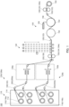
- FIG. 1 schematically illustrates an exemplary configuration of a production apparatus for producing a fiber-reinforced resin in which reinforcing fibers are arranged to be oriented in a single direction according to one embodiment of the present invention.
- FIG. 1 schematically illustrates an exemplary configuration of the production apparatus for producing a UD sheet as the fiber-reinforced resin.
- Production apparatus 100 for producing the fiber-reinforced resin in which the reinforcing fibers are arranged to be oriented in a single direction includes fiber feeding section 110, guide path 120, switching apparatus 130a and switching apparatus 130b, accumulator 140, impregnation section 150, and winding section 160.
- Fiber feeding section 110 supplies the reinforcing fibers that are to be impregnated with resin in impregnation section 150 to form the fiber-reinforced resin.
- fiber feeding section 110 is creel 114 in which a plurality of spindles 112 are disposed, and bobbins 116 around which reinforcing fibers 200 are wound are rotatably installed respectively on spindles 112.
- each of reinforcing fibers 200 is a carbon fiber.
- reinforcing fiber 200 may be any fiber used for the fiber-reinforced resin, such as a glass fiber and aramid fiber.
- Guide path 120 guides reinforcing fibers 200 supplied from fiber feeding section 110 to the components of switching apparatus 130, accumulator 140, impregnation section 150, and winding section 160 in this order.
- Guide path 120 includes a plurality of guide rolls 122, and, feeders 124 each of which is composed of two rolls opposed to each other across reinforcing fiber 200. The two rolls constituting feeder 124 rotate in opposite directions and in such a manner as to nip the reinforcing fiber, thereby moving reinforcing fiber 200 on a movement path formed by guide rolls 122.
- Reinforcing fiber 200 is continuously fed out from each of bobbins 116 and moved by feeders 124. Thus, reinforcing fibers 200 continue to move on guide path 120 without interrupted.
- feeders 124 apply a predetermined tension to reinforcing fibers 200. Due to the tension, the reinforcing fibers are linearly oriented in the moving direction.
- the UD sheet is produced which includes a plurality of reinforcing fibers 200 arranged to be oriented in a single direction and a matrix resin impregnating reinforcing fibers 200.
- guide path 120 includes two feeders 124a and 124b.
- Feeder 124a is disposed on the downstream side of switching apparatus 130 and on the upstream side of accumulator 140 in the moving direction of reinforcing fibers 200, and adjusts the moving speed of reinforcing fibers 200 until the reinforcing fibers pass through switching apparatus 130 after fed out from fiber feeding section 110.
- Feeder 124b is disposed on the downstream side of impregnation section 150 and on the upstream side of winding section 160 in the moving direction of reinforcing fibers 200, and adjusts the moving speed of reinforcing fibers 200 passing through impregnation section 150.
- the moving speed of reinforcing fibers 200 by feeder 124b defines the production speed of the fiber-reinforced resin produced by production apparatus 100.
- guide path 120 includes a plurality of holding sections 126a and 126b that, at different positions, hold reinforcing fibers 200a and reinforcing fibers 200b respectively fed out from bobbins 116a and bobbins 116b different from bobbin 116a.
- guide path 120 includes uniting section 128 for uniting reinforcing fibers 200a and reinforcing fibers 200b held by holding section 126a and holding section 126b, respectively.
- Guide path 120 guides reinforcing fibers 200 united at uniting section 128 to accumulator 140 and impregnation section 150.
- FIG. 2 schematically illustrates a state in which reinforcing fibers 200a and reinforcing fibers 200b are united at uniting section 128.
- holding section 126a introduces, into uniting section 128, a plurality of reinforcing fibers 200a fed out from a plurality of bobbins 116a (six reinforcing fibers 200a fed out from six bobbins 116a in FIG. 2 ).
- holding section 126b introduces, into uniting section 128, a plurality of reinforcing fibers 200b fed out from a plurality of bobbins 116b (six reinforcing fibers 200b fed out from six bobbins 116b in FIG. 2 ).
- FIG. 128 schematically illustrates a state in which reinforcing fibers 200a and reinforcing fibers 200b are united at uniting section 128.
- holding section 126a introduces, into uniting section 128, a plurality of reinforcing fibers 200a fed out
- reinforcing fibers 200 fed out from one bobbins 116 are collectively described as a single reinforcing fiber, but actually, each single reinforcing fiber 200 is a bundle (tow) of single fibers in which a plurality of single fibers are assembled and bound together by a binding member.
- a single tow is represented as single reinforcing fiber 200.
- Each of holding section 126a and holding section 126b holds the plurality of reinforcing fibers 200 such that the reinforcing fibers are spaced from one another. Then, in uniting section 128, one of reinforcing fibers 200b held by holding section 126b is disposed in a gap between reinforcing fibers 200a held by holding section 126a. Then, uniting section 128 alternately disposes reinforcing fibers 200a held by holding section 126a and reinforcing fibers 200b held by holding section 126b, and pressurizes reinforcing fibers 200 in the thickness direction by the pair of rolls 128a and 128b to arrange and unite the reinforcing fibers into a sheet shape.
- the plurality of reinforcing fibers 200 fed out from the plurality of bobbins 116 can be arranged in a planar shape (sheet shape) without any gap.
- the gaps between reinforcing fibers 200 may be more unlikely to occur. It is also possible to more evenly dispose the plurality of reinforcing fibers 200 fed out from the plurality of bobbins 116, and to suppress variations in physical properties of the UD sheet that could be caused due to uneven arrangement of the fibers in the produced UD sheet that is caused due to interference between the fibers during fiber opening.
- Switching apparatus 130a and switching apparatus 130b are disposed on the respective holding sections, and switch the reinforcing fibers held by the respective holding sections from the preceding reinforcing fibers to the new reinforcing fibers.
- the switching of reinforcing fibers 200 by switching apparatus 130a and switching apparatus 130b is performed when the remaining amount of reinforcing fibers 200a that can be fed out from bobbins 116a is small. Whether or not the remaining amount of reinforcing fibers 200a is small may be determined based on the amount of reinforcing fibers 200a having been fed out from bobbins 116a, or may be determined by measuring the amount of reinforcing fibers 200a currently wound on bobbins 116a (e.g., measuring the thickness or the like of the reinforcing fiber currently wound), or by reading, from fed reinforcing fibers 200a, a mark that is attached to reinforcing fibers 200a in advance and indicates that the remaining amount is small.
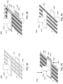
- FIGS. 3A to 3D schematically illustrate a state in which switching apparatus 130a according to the present embodiment switches preceding reinforcing fibers 210 held by holding section 126a to new reinforcing fibers 220.
- FIG. 3A schematically illustrates switching apparatus 130a prior to switching.
- Switching apparatus 130a includes pressurization head 1310 and pedestal portion 1320 disposed at positions opposed to each other such that the moving reinforcing fibers are interposed between the pressurization head and the pedestal portion.
- Pressurization head 1310 is heated by a heating section (not illustrated) and moves in a direction toward and away from pedestal portion 1320 by cylinder 1330 (vertical direction in the figures).
- Pedestal portion 1320 is heated by a heating section (not illustrated) and moves in a direction toward and away from pressurization head 1310 by cylinder 1340 (vertical direction in the figures). Note that pedestal portion 1320 does not have to be moved in the vertical direction by cylinder 1340, and a configuration may be adopted in which reinforcing fibers 200 are pressed against pedestal portion 1320 by the vertical movement of pressurization head 1310.
- FIGS. 3B and 3C schematically illustrate switching apparatus 130a at a time when the reinforcing fibers to be impregnated with resin are switched to new reinforcing fibers.
- FIG. 3B illustrates the operation of switching apparatus 130a at a time when the remaining amount of reinforcing fibers 200a (preceding reinforcing fibers 210) that can be fed out from bobbins 116a is small.
- FIG. 2 illustrates the remaining amount of reinforcing fibers 200a (preceding reinforcing fibers 210) that can be fed out from bobbins 116a is small.
- gripping section 1360 grips the end portions of reinforcing fibers 200a (new reinforcing fibers 220) wound around those bobbins 116a which are not feeding out the reinforcing fibers, and moves these reinforcing fibers through gaps between moving preceding reinforcing fibers 210 spaced from one another.
- preceding reinforcing fibers 210 continue to pass between pressurization head 1310 and pedestal portion 1320. Therefore, preceding reinforcing fibers 210 and new reinforcing fibers 220 move between pressurization head 1310 and pedestal portion 1320 while temporarily arranged in a planar shape (sheet shape) without any gap.
- resin film 230 which is a second resin in the form of a thin film, is supplied from a supply section (not illustrated) to each of the surfaces of pressurization head 1310 and pedestal portion 1320 facing each other.
- the resin film may be any resin in the form of a thin film as long as it can be fused to preceding reinforcing fibers 210 and new reinforcing fibers 220 by heating and pressurization, and may be a resin having a larger thickness such as a sheet. Because of the use of the second resin in the form of a thin film which melts by heating or the like, it is possible to cool and solidify the second resin after fusion so as to prevent the second resin from contaminating other components of production apparatus 100.
- pressurization head 1310 and pedestal portion 1320 are heated by the heating sections to melt resin films 230.
- cylinder 1330 moves pressurization head 1310 in the direction toward pedestal portion 1320
- cylinder 1340 moves pedestal portion 1320 in the direction toward pressurization head 1310.
- molten resin films 230 make contact respectively with both of preceding reinforcing fibers 210 and new reinforcing fibers 220, are disposed to sandwich the reinforcing fibers, pressurized, and fused to preceding reinforcing fibers 210 and new reinforcing fibers 220.
- pressurization head 1310 and pedestal portion 1320 act as a pressing section in the present embodiment.
- the configuration of the pressing section is not limited to pressurization head 1310 and pedestal portion 1320 described above, and for example, a configuration may be adopted in which molten resin films 230 are brought into contact with preceding reinforcing fibers 210 and new reinforcing fibers 220 by rotary rolls and the resin films are pressurized by these rolls.
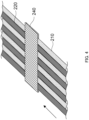
- bonded body 240 is formed by fusing resin films 230 to preceding reinforcing fibers 210 and new reinforcing fibers 220 arranged in a planar shape.
- preceding reinforcing fibers 210 and new reinforcing fibers 220 are firmly connected to each other by fusion of resin films 230.
- Bonded body 240 may have such a strength that preceding reinforcing fibers 210 and new reinforcing fibers 220 are not easily untied even by a tension applied to reinforcing fibers 200 by production apparatus 100.
- bonded body 240 may have a strength preventing the bonded body from being untied when the tension of 1,000 cN is applied to the bonded body in the length direction of the reinforcing fibers.
- each of resin films 230 is preferably 1 ⁇ m or more and 1 mm or less, and more preferably 25 ⁇ m or more and 150 ⁇ m or less.
- the length of resin film 230 in the moving direction of reinforcing fiber 200 is preferably equal to or greater than 1 cm, and more preferably equal to or greater than 5 cm.
- the length of resin film 230 is preferably equal to or less than 200 cm, and more preferably equal to or less than 100 cm.
- the width of each of resin films 230 in the direction perpendicular to the moving direction of reinforcing fibers 200 is preferably wider than the width of all reinforcing fibers 200 moving in parallel.
- Resin film 230 may be a film made of the same kind of resin as the resin (first resin) impregnating reinforcing fibers 200 in impregnation section 150, or may be a film made of a different resin. It is preferable that, among these resins of the same kind and different kinds, the resin film be made of the same kind of resin having high affinity with the first resin that makes contact with reinforcing fibers 200 and bonded body 240 in impregnation section 150.
- the resin forming the resin film be a resin having a glass-transition temperature higher than the heating temperature in impregnation section 150.
- switching apparatus 130a connects preceding reinforcing fibers 210 and new reinforcing fibers 220 by forming bonded body 240.
- FIG. 3D schematically illustrates switching apparatus 130a after switching. After the formation of bonded body 240, preceding reinforcing fibers 210 are cut to stop the feeding of the preceding reinforcing fibers. Accordingly, only new reinforcing fibers 220 are fed out and sent to impregnation section 150. Since new reinforcing fibers 220 sent at this time are connected to preceding reinforcing fibers 210 by bonded body 240, it is possible to continuously produce the UD sheet while switching the reinforcing fibers, without stopping production apparatus 100.
- the switching of the reinforcing fibers in one switching apparatus 130a has been described so far.
- the switching from the preceding reinforcing fibers to the new reinforcing fibers by forming the bonded body in the same manner is simultaneously performed also in the other switching apparatus 130b in the present embodiment.
- the new reinforcing fibers after the switching are arranged and united in a sheet shape at uniting section 128.
- bonded body 240 is formed by disposing new reinforcing fibers 220 between adjacent reinforcing fibers of a plurality of moving preceding reinforcing fibers 210 spaced from one another. After the switching, new reinforcing fibers 220 are moved to positions corresponding to the gaps between the fibers of preceding reinforcing fiber 210.
- each of two switching apparatuses 130a and 130b exchanges the positions where preceding reinforcing fibers 210 move with the positions where new reinforcing fibers 220 move.
- production apparatus 100 may slow the moving speed of reinforcing fibers 200 until the reinforcing fibers pass switching apparatus 130 after being fed out from fiber feeding section 110, by using feeder 124a disposed on the downstream side of switching apparatus 130a and switching apparatus 130b and on the upstream side of accumulator 140.
- feeder 124a disposed on the downstream side of switching apparatus 130a and switching apparatus 130b and on the upstream side of accumulator 140.
- accumulator 140 adjusts the length of the movement path of reinforcing fibers 200 to keep the moving speed of the reinforcing fibers at impregnation section 150 (the moving speed of the reinforcing fibers between accumulator 140 and winding section 160) at the same speed as in a case where the switching is not performed.
- accumulator 140 is configured to be capable of changing the length of the movement path of reinforcing fibers 200 to change the length (amount) of reinforcing fibers 200 passing through accumulator 140. Further, when reinforcing fibers 200 are not switched, the movement path of reinforcing fibers 200 at accumulator 140 is lengthened to increase the length (amount) of reinforcing fibers 200 passing through accumulator 140, and when switching apparatus 130 switches reinforcing fibers 200, the length (amount) of reinforcing fibers 200 passing through accumulator 140 is reduced.
- the amount of reinforcing fibers 200 sent from accumulator 140 to impregnation section 150 can be kept constant.
- accumulator 140 accumulates reinforcing fibers 200 when reinforcing fibers 200 are not switched, and discharges accumulated reinforcing fibers 200 little by little when switching apparatus 130 switches reinforcing fibers 200. Accordingly, the amount of reinforcing fibers 200 sent from accumulator 140 to impregnation section 150 can be kept constant.
- Impregnation section 150 opens reinforcing fibers 200 and impregnates reinforcing fibers 200 with resin.
- Impregnation section 150 first moves reinforcing fibers 200 along the surface of fiber-opening roller 152, and abrades reinforcing fibers 200 against fiber-opening roller 152 to open reinforcing fibers 200. Next, opened reinforcing fibers 200 are guided to impregnation roller 154 and moved along the surface of impregnation roller 154. Molten resin 158 (first resin) extruded from extruder 156 is attached to and rotationally moves on the surface of impregnation roller 154, and reinforcing fibers 200 and the surface of impregnation roller 154 come into contact with each other, whereby resin 158 impregnates reinforcing fibers 200.
- reinforcing fibers 200 may be abraded against a plurality of fiber-opening rollers during fiber opening, or vibrations may be applied to reinforcing fibers 200 during fiber opening.
- a sizing agent for facilitating impregnation with resin 158 may be applied to reinforcing fibers 200 during fiber opening.
- reinforcing fibers 200 may be impregnated with a resin by a method such as immersing the reinforcing fibers in a bath of molten resin.
- bonded body 240 which is a connecting portion of reinforcing fibers 200, is a portion where another resin derived from resin films 230 is mixed or the ratio between reinforcing fibers 200 and the resin is changed. Therefore, the portion corresponding to bonded body 240 may be cut from the UD sheet and removed during the production or after the production.
- production apparatus 100 may include a removal section that removes the portion where bonded body 240 is formed by fusing resin films 230 (portion including bonded body 240 and the first resin).
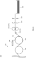
- production apparatus 300 for producing the fiber-reinforced resin in which the reinforcing fibers are arranged to be oriented in a single direction may include, on the downstream side of impregnation section 150, thickness measurement section 310 for measuring the thickness of a composite formed by impregnating reinforcing fibers 200 with resin, and cutting section 320 for cutting the composite. Since the configuration of production apparatus 300 on the upstream side of impregnation section 150 can be the same as that of production apparatus 100 illustrated in FIG. 1 , only the configuration on the downstream side of impregnation section 150 is illustrated in FIG. 6 .
- the composite to be subjected to thickness measurement and cutting may be a UD sheet in which the impregnating resin is cooled and solidified, or may be a composite before being cooled and solidified.
- Thickness measurement section 310 measures the thickness of the composite after impregnation with the resin.
- the portion where bonded body 240 is formed includes a larger amount of reinforcing fibers 200 than other portions, and/or the thickness of resin films 230 is added at this portion. Accordingly, the thickness of this portion of the composite is larger than the thickness of the other portions. Therefore, the portion where the thickness measured by thickness measurement section 310 is large can be determined as a portion of the composite where bonded body 240 is formed.
- Cutting section 320 cuts the composite at positions before and after the portion where the thickness measured by thickness measurement section 310 is large and which is thus determined to be the portion where bonded body 240 is formed. As a result, the portion where bonded body 240 is formed can be removed from the composite.
- cutting section 320 may also remove, from the composite, these portions of new reinforcing fibers 220 or preceding reinforcing fibers 210 that do not form bonded body 240.
- cutting section 320 may remove, from the composite, a portion of the composite that includes a portion corresponding to bonded body 240 and a portion that is shorter than the same length as bonded body 240 (preferably, shorter than half the length of bonded body 240) on each of the upstream side and on the downstream side along the moving direction of reinforcing fibers 200.
- the UD sheet from which the above-described portion have been removed is collected as the UD sheet in a sheet shape in collection section 330.
- a plurality of UD sheets are stacked and collected in collection section 330, but may also be collected in the form of a roll.
- the method of removing the portion where bonded body 240 is formed is not limited to the above-described cutting, and the above-described portion may be removed by punching or the like, for example.
- the method of determining the above-described portion is not limited to the determining method based on the thickness of the composite. For example, removal may be performed after reinforcing fibers 200 of a predetermined length (length corresponding to one bobbin) is impregnated with resin, or may be performed based on a signal indicating that the reinforcing fibers have been connected in switching apparatus 130a and switching apparatus 130b.
- FIG. 7 schematically illustrates an exemplary configuration of a production apparatus for producing a fiber-reinforced resin in which reinforcing fibers are arranged to be oriented in a single direction according to another embodiment of the present invention.
- FIG. 7 schematically illustrates an exemplary configuration of the production apparatus for producing, as the fiber-reinforced resin, a pelletized resin composition (Long Fiber Thermoplastics (LFT)) including the reinforcing fibers arranged to be oriented in a single direction.
- LFT Long Fiber Thermoplastics
- Production apparatus 700 for producing the fiber-reinforced resin in which the reinforcing fibers are arranged to be oriented in a single direction includes fiber feeding section 110, guide path 720, switching apparatus 730, accumulator 140, dividing section 770, impregnation section 750, removal section (thickness measurement section 310 and cutting section 320), and collection section 780.
- reinforcing fibers 200 are introduced respectively into individual die holes, and each of reinforcing fibers 200 is impregnated with the first resin. Then, a corresponding number of pellets (LFT) corresponding to the number of die holes that are formed by impregnating each of reinforcing fibers 200 with the first resin are obtained.
- LFT pellets
- guide path 720 does not have a configuration in which the reinforcing fibers from different holding sections 126 are united at uniting section 128, and moving reinforcing fibers 200 spaced from one another are guided to impregnation section 750 while being kept spaced from one another (without arranging reinforcing fibers 200 in a planar shape having no gap). Therefore, switching apparatus 730 also forms a bonded body without arranging preceding reinforcing fibers 210 and new reinforcing fibers 220 in a planar shape even during switching of reinforcing fibers 200.
- production apparatus 700 includes dividing section 770 that cuts the bonded body in the longitudinal direction (in the moving direction of reinforcing fibers 200) before the bonded body is introduced into impregnation section 750, to divide the bonded body for each reinforcing fiber 200. Further, in production apparatus 700, impregnation section 750 supplies the molten first resin to reinforcing fibers 200 (the bundles of reinforcing fibers in fact) passing through the insides of the die holes, and impregnates each of reinforcing fibers 200 with the first resin. Then, in the production apparatus, collection section 780 cuts, into pellets, a long composite obtained by impregnating reinforcing fibers 200 with the resin, and collects the pellets.
- Production apparatus 700 according to the present embodiment may have the same configuration as that of production apparatus 100 according to Embodiment 1 with respect to other configurations, and therefore, description of the same configurations will be omitted in the following.
- guide path 720 guides reinforcing fibers 200 supplied from fiber feeding section 110 to component sections of switching apparatus 730, accumulator 140, dividing section 770, impregnation section 750, and winding section 160 in this order, while moving the reinforcing fibers spaced from one another.
- the configurations and operations of accumulator 140 and winding section 160 are the same as those of production apparatus 100 according to Embodiment 1.
- FIGS. 8A to 8D illustrate a state in which switching apparatus 730 according to the present embodiment switches preceding reinforcing fibers 210 held by holding section 126 to new reinforcing fibers 220.
- FIG. 8A schematically illustrates switching apparatus 730 prior to switching.
- Switching apparatus 730 includes pressurization head 7310 that is vertically moved by cylinder 7330 and pedestal portion 7320 that is vertically moved by cylinder 7340, the pressurization head and the pedestal portion being disposed at positions opposed to each other such that moving reinforcing fibers are interposed between the pressurization head and the pedestal portion.
- the configurations and operations of pressurization head 7310 and pedestal portion 7320 are the same as those of switching apparatus 130 according to Embodiment 1.
- FIGS. 8B and 8C schematically illustrate switching apparatus 730 at a time when the reinforcing fibers to be impregnated with resin are switched to the new reinforcing fibers.
- FIG. 8B illustrates the operation of switching apparatus 730 at a time when the remaining amount of reinforcing fibers 200a (preceding reinforcing fibers 210) that can be fed out from bobbins 116a is small.
- FIG. 8B illustrates the operation of switching apparatus 730 at a time when the remaining amount of reinforcing fibers 200a (preceding reinforcing fibers 210) that can be fed out from bobbins 116a is small.
- gripping section 7360 grips the end portions of reinforcing fibers 200a (new reinforcing fibers 220) wound on bobbins 116a that are not feeding out the reinforcing fibers, and moves these reinforcing fibers to a position where these reinforcing fibers overlap vertically (in the pressing direction of pressurization head 7310 and pedestal portion 7320) with moving preceding reinforcing fibers 210 spaced from one another.
- preceding reinforcing fibers 210 continue to pass between pressurization head 7310 and pedestal portion 7320. Therefore, preceding reinforcing fibers 210 and new reinforcing fibers 220 move between pressurization head 7310 and pedestal portion 7320 while temporarily arranged to overlap with each other.
- resin film 230 is supplied from a supply section (not illustrated) to each of the surfaces of pressurization head 1310 and pedestal portion 1320 facing each other.
- pressurization head 7310 and pedestal portion 7320 are heated by the heating section to melt resin films 230.
- cylinder 7330 moves pressurization head 7310 in the direction toward pedestal portion 7320
- cylinder 7340 moves pedestal portion 7320 in the direction toward pressurization head 7310.
- molten resin films 230 make contact with preceding reinforcing fibers 210 and new reinforcing fibers 220, are disposed to sandwich the reinforcing fibers, pressurized, and fused to preceding reinforcing fibers 210 and new reinforcing fibers 220.
- pressurization head 7310 and pedestal portion 7320 act as a pressing section in the present embodiment.
- bonded body 840 is formed by fusing resin films 230 to preceding reinforcing fibers 210 and new reinforcing fibers 220 arranged to overlap with each other.
- preceding reinforcing fibers 210 and new reinforcing fibers 220 are firmly connected by fusion of resin films 230.
- Bonded body 840 may have such a strength that preceding reinforcing fibers 210 and new reinforcing fibers 220 are not easily untied even by a tension applied to reinforcing fibers 200 by production apparatus 100.
- bonded body 840 may have a strength preventing the bonded body from being untied when the tension of 1,000 cN is applied to the bonded body in the length direction of the reinforcing fibers.
- FIG. 10 schematically illustrates a state in which reinforcing fibers 200 on which bonded body 240 is formed are introduced into dividing section 770 and impregnation section 750.
- Reinforcing fibers 200 having moved to dividing section 770 via switching apparatus 730 partly include bonded body 840 that is formed at the time of switching from preceding reinforcing fibers 210 to new reinforcing fibers 220 and that is formed in a sheet shape by fusion of resin films 230.
- Dividing section 770 cuts, in the longitudinal direction, bonded body 240, which is formed in a sheet shape at a part of the reinforcing fibers by fusion of resin films 230, so as to divide bonded body 240 for each reinforcing fiber 200.
- Dividing section 770 may have a configuration similar to that of a known slitter that cuts a film in the moving direction.
- Impregnation section 750 includes fiber-opening roller 752 and impregnation die 754.
- Impregnation die 754 includes a plurality of die holes 754a, all of which extend through impregnation die 754 in the moving direction of reinforcing fibers 200.
- guide path 720 introduces reinforcing fibers 200 respectively into different die holes 754a in impregnation section 750.
- Molten resin extruded from extruder 756 (first resin) is supplied to the inside of each of die holes 754a.
- Reinforcing fibers 200 make contact with the molten resin inside die hole 754a, and make contact with different wall surfaces of die hole 754a. Accordingly, penetration of the resin into the inside of the bundle of reinforcing fibers 200 is promoted.
- resin 158 impregnates reinforcing fibers 200.
- a long composite formed by impregnating the bundle of reinforcing fibers with the first resin can be obtained.
- a portion where bonded body 240 is formed by fusion of resin films 230 may be removed by the removal section (thickness measurement section 310 and cutting section 320).
- the configuration of the removal section is not limited to the configuration including thickness measurement section 310 and cutting section 320.
- collection section 780 includes pelletizing cutter 782 for cutting the long composite into pieces of a predetermined length, and collection container 784 that collects the cut pelletized composite.
- the cut pelletized composite (LFT) can thus be obtained.
- production apparatus 700 may collect the long composite before pelletizing.
- the material of the above reinforcing fibers is not particularly limited.
- carbon fibers, glass fibers, aramid fibers, alumina fibers, silicon carbide fibers, boron fibers, metal fibers, and the like can be used as the reinforcing fibers.
- the reinforcing fibers preferably have an average diameter of 1 ⁇ m or more and 20 ⁇ m or less, and more preferably 4 ⁇ m or more and 10 ⁇ m or less.
- the reinforcing fibers may be subjected to sizing treatment with a sizing agent.
- the sizing agent is not particularly limited, but is preferably a modified polyolefin, and more preferably a modified polyolefin containing a carboxylic acid metal salt.
- the modified polyolefin is, for example, a modified polyolefin in which a carboxylic acid group, a carboxylic acid anhydride group, or a carboxylic acid ester group is grafted onto a polymer chain of an unmodified polyolefin, and a salt is formed between the functional group and a metal cation.
- the above-described unmodified polyolefin is preferably an ethylene polymer with a content of 50 mol% or more of the constituent units derived from ethylene, or a propylene polymer with a content of 50 mol% or more of the constituent units derived from propylene.
- ethylene polymer examples include ethylene homopolymer and copolymer of ethylene and a-olefin with 3 to 10 carbon atoms.
- Examples of the above-described propylene polymer include propylene homopolymer, and copolymer of propylene and ethylene or ⁇ -olefin with 4 to 10 carbon atoms.
- the unmodified polyolefin is preferably homopolypropylene, homopolyethylene, an ethylene-propylene copolymer, a propylene-1-butene copolymer, or an ethylene-propylene-1-butene copolymer.
- the reinforcing fibers may be bundled to form a fiber bundle.
- the number of single threads per bundle of bundled reinforcing fibers is preferably 100 or more and 100,000 or less, and more preferably 1,000 or more and 50,000 or less.
- the material of the above-described matrix resin is not particularly limited, and may be a thermoplastic resin or a thermosetting resin.
- the thermoplastic resin include polyolefin resins including polypropylene resins, polyethylene resins, and the like, polyamide resins, polyester resins, polycarbonate resins, polyacetal resins, polyether ketone resins, polyether ether ketone resins, polysulfone resins, and the like.
- the polypropylene resins and polyamide resins are preferable among the above resins.
- the above-described matrix resin may contain the modified polyolefin described above.
- preceding reinforcing fibers 210 and new reinforcing fibers 220 are reinforcing fibers made of the same material, but preceding reinforcing fibers 210 and new reinforcing fibers 220 may be reinforcing fibers made of respective different materials.
- Embodiment 1 has been described in relation to an example in which each of the two holding sections includes the switching apparatus, but may also has a configuration in which three or more holding sections include respective switching apparatuses, and unite reinforcing fibers from these holding sections at a uniting section, or a configuration in which a single switching apparatus is disposed on a single holding section as in Embodiment 2 and the holding section does not include any uniting section.
- Embodiment 1 the configuration in which the bonded body in which the preceding reinforcing fibers and the new reinforcing fibers are arranged in a planar shape without gaps has been described by way of example. However, the bonded body in which the preceding reinforcing fibers and the new reinforcing fibers are arranged in an overlapping manner as in Embodiment 2 may be formed.
- Embodiment 2 may have a configuration in which a plurality of holding sections may include switching apparatuses, respectively, and the reinforcing fibers from these holding sections may be united at a uniting section.
- the uniting section only needs to unite the reinforcing fibers such that bundles of the reinforcing fibers are disposed so as to be introduced into respective different die holes, by disposing the reinforcing fibers from the respective holding sections such that the reinforcing fibers are spaced from one another or overlap with one another.
- each of the above embodiments has been described in which the upper and lower two resin films are fused to the reinforcing fibers, but a resin film may be fused to only one of the surfaces. Further, a plurality of resin films may be fused. The number of bonded bodies formed by fusing the resin film may be only one per switching occasion, or a plurality of bonded bodies may be formed by performing fusion of the resin film a plurality of times.
- the material of the resin film be a thermoplastic resin from the viewpoint of facilitating melting and fusion.
- the thermoplastic resin include polyolefin resins including polypropylene resins and polyethylene resins, polyamide resins, polyester resins, polycarbonate resins, polyacetal resins, polyether ketone resins, polyether ether ketone resins, polysulfone resins, and the like.
- the polypropylene resins and polyamide resins are preferable among the above resins.
- the second resin in the form of a thin film is melted by heating and fused to the preceding reinforcing fibers and new reinforcing fibers, but the second resin may also be fused by irradiation with an electromagnetic wave (such as infrared rays), ultrasonic waves, and/or the like.
- an electromagnetic wave such as infrared rays
- ultrasonic waves and/or the like.
- the switching apparatus in each of the above-described embodiments may include a cooling section that cools and solidifies the second resin fused.
- the cooling section may be of a contact type or a non-contact type.
- the reinforcing fibers fed out in each of the above-described embodiments may be used not only for producing the UD sheet or LFT, but also for producing a fiber-reinforced resin that is formed, for example, by chopping the reinforcing fibers and kneading it with a matrix resin, and in which the reinforcing fibers are randomly oriented and arranged.
- the UD sheet or LFT produced by the above production apparatus can be used for automotive components including various modules such as instrument panels, door beams, undercovers, lamp housings, pedal housings, radiator supports, spare tire covers, front ends, and the like; electric and electronic components including notebook computers, mobile phones, digital still cameras, PDA, plasma displays, and the like; and home and office appliance components such as telephones, facsimiles, VTR, copiers, televisions, microwave ovens, audio equipment, toiletries, LaserDiscs (registered trademark), refrigerators, air conditioners, and the like.
- the UD sheet can also be used for pipes, pressure vessels, and the like by further forming the UD sheet.
- UD sheet examples include primary structure materials including, for example, main wings, vertical and horizontal tails, secondary structure materials including, for example, ailerons, rudders and elevators, interior materials including, for example, seats and tables, component members for common air vehicles such as airplanes and helicopters, including for example, power plants, hydraulic cylinders and composite brakes, rocket component members including, for example, nozzle cones and motor cases, satellite component members including, for example, antennas, structures, solar panels, battery cases and telescopes, mechanical component members including, for example, frames, shafts, rollers, leaf springs, machine tool heads, robot arms, transport hands and synthetic fiber pots, component members for high-speed rotating bodies, including, for example, centrifuge rotors and uranium concentration cylinders, electronic and electric component members including, for example, parabola antennas, battery members, radars, acoustic speaker cones, computer components, printer components, personal computer housings and tablet housings, component members for automobiles and bikes, including, for example, frame components,
- a production apparatus for producing a fiber-reinforced resin in which reinforcing fibers are arranged to be oriented in a single direction is capable of connecting the preceding and following reinforcing fibers with a relatively simple configuration at the time of switching the reinforcing fibers. Therefore, the present disclosure is expected to facilitate continuous production of the fiber-reinforced resin to contribute to development in various fields using the fiber-reinforced resin, particularly the UD sheet or LFT.
Landscapes
- Engineering & Computer Science (AREA)
- Mechanical Engineering (AREA)
- Chemical & Material Sciences (AREA)
- Composite Materials (AREA)
- Textile Engineering (AREA)
- Reinforced Plastic Materials (AREA)
- Moulding By Coating Moulds (AREA)
Abstract
Description
- The present invention relates to a production apparatus for producing a fiber-reinforced resin and a production method for producing a fiber-reinforced resin.
- A fiber-reinforced resin (hereinafter, simply referred to as "Uni-Direction (UD) sheet") is known, which includes a plurality of reinforcing fibers arranged to be oriented in a single direction and a resin composition (matrix resin) impregnating the reinforcing fibers. This UD sheet is lighter in weight than a metal sheet, and nevertheless has a higher mechanical strength. Thus, the UD sheet has been studied for use as a reinforcing material or the like for covering the surface of a resin-molded article.
- The UD sheet is usually produced by impregnating a reinforcing fiber fed out from a roll body with a resin material (see, for example, Patent Literature (hereinafter, referred to as "PTL") 1).
- When the UD sheet is produced, a plurality of roll bodies are disposed in a creel, and reinforcing fibers are fed out from the roll bodies. When one of the roll bodies finishes feeding the reinforcing fibers, the reinforcing fibers impregnated with the resin are switched to the reinforcing fibers (hereinafter, also simply referred to as "new reinforcing fibers") which are newly fed out from another one of the roll bodies. At this time, the new reinforcing fibers are connected to the reinforcing fibers (hereinafter, also simply referred to as "preceding reinforcing fibers") from the roll body which finishes feeding, so that the new reinforcing fibers are also impregnated with the resin continuously.
- As a method for connecting the reinforcing fibers, PTL 2 describes a method of tying a fibrous material that is characterized by unlikeliness for a knot to be untied even when the knot is pulled from opposite ends, and ease of untying the knot after the fibrous material is cut.
- Further, PTL 3 describes a method of coupling reinforcing fibers to one another by entangling the fibers with each other by an air jet, and PTL 4 describes an apparatus that includes a splicer for performing the coupling method and that automatically replaces a bobbin for supplying reinforcing fibers.
-
-
PTL 1
Japanese Unexamined Patent Application Publication (Translation of PCT Application) No. 2001-525749 - PTL 2
Japanese Patent Application Laid-Open No. 2011-94244 - PTL 3
Japanese Patent Application Laid-Open No. 2006-52043 - PTL 4
Japanese Patent Application Laid-Open No. 2009-66917 - When the UD sheet is produced, the reinforcing fibers are moved to a resin impregnation section while being tensioned. Therefore, when the reinforcing fibers are switched, it is necessary to connect the reinforcing fibers to each other so as not to be untied even by the above-described tension. PTL 2 describes the method of tying reinforcing fibers, in which a knot is unlikely to be untied even when pulled from opposite ends (even when tension is applied). However, this tying method is complicated, and automation by a machine is difficult. Thus, the reinforcing fibers need to be connected manually by an operator. When the reinforcing fibers are manually connected, a production apparatus needs to be stopped for a long period of time at the time of connection, and thus it is difficult to improve the production efficiency of the UD sheet.
- Meanwhile, PTL 3 and PTL 4 describe the method of connecting reinforcing fibers by entangling the fibers with each other by an air jet, and the automatic switching apparatus that uses the connecting method and that automatically switches the reinforcing fibers. However, the connection of the reinforcing fibers by the air jet is a relatively weak connection, and there is a possibility that the reinforcing fibers may be untied by tension.
- Further, in production of the UD sheet, a plurality of reinforcing fibers fed out from a plurality of rolls are laterally arranged into a sheet shape, and the reinforcing fibers arranged in the sheet shape are impregnated with a resin. Therefore, an attempt to automate the switching of the reinforcing fibers by the method described in PTL 3 and PTL 4 simultaneously necessitates preparation of the same number of switching apparatuses as roll bodies that feed out the reinforcing fibers. It is thus not practical.
- These issues can also arise when producing, as a fiber-reinforced resin, a pelletized resin composition (LFT) containing reinforcing fibers arranged to be oriented in a single direction.
- The present invention has been made in view of the above-described problems of the prior art, and an object of the present invention is to provide a production apparatus for producing a fiber-reinforced resin in which preceding and following reinforcing fibers can be connected at the time of switching of the reinforcing fibers, and in which reinforcing fibers are arranged to be oriented in a single direction, and a production method for producing the fiber-reinforced resin using the apparatus.
- A production apparatus for producing a fiber-reinforced resin in which a reinforcing fiber is arranged to be oriented in a single direction according to one embodiment of the present invention for solving the above problem includes: an impregnation section that impregnates the reinforcing fiber with a first resin; and a switching apparatus that switches the reinforcing fiber from a preceding reinforcing fiber to a new reinforcing fiber at an upstream side of the impregnation section. When switching the reinforcing fiber, the switching apparatus connects the new reinforcing fiber to the preceding reinforcing fiber by forming a bonded body in which the preceding reinforcing fiber and the new reinforcing fiber are bonded by fusing a melted second resin in a form of a thin film.
- Further, a production method for producing a fiber-reinforced resin in which a reinforcing fiber is arranged to be oriented in a single direction according to another embodiment of the present invention for solving the above problem includes producing the fiber-reinforced resin while connecting the reinforcing fiber to one another by using a production apparatus for producing the fiber-reinforced resin.
- According to the present invention, a production apparatus for producing a fiber-reinforced resin in which the reinforcing fibers are arranged to be oriented in a single direction, the production apparatus being capable of connecting preceding and following reinforcing fibers at the time of switching of the reinforcing fibers with a relatively simple configuration, and, a production method for producing the fiber-reinforced resin using the apparatus are provided.
-
-
FIG. 1 schematically illustrates an exemplary configuration of a production apparatus for producing a fiber-reinforced resin in which reinforcing fibers are arranged to be oriented in a single direction according to one embodiment of the present invention; -
FIG. 2 schematically illustrates a state in which the reinforcing fibers are united at a uniting section; -
FIGS. 3A to 3D schematically illustrate a state in which a switching apparatus switches the reinforcing fibers held by a holding section to new reinforcing fibers; -
FIG. 4 schematically illustrates a bonded body formed by fusing resin films to preceding reinforcing fibers and new reinforcing fibers arranged in a planar shape; -
FIG. 5A schematically illustrates the uniting section before switching; -
FIG. 5B schematically illustrates the uniting section after switching; -
FIG. 6 schematically illustrates an exemplary configuration of the production apparatus for producing the fiber-reinforced resin, including a removal section that removes a portion where a composite is formed; -
FIG. 7 schematically illustrates an exemplary configuration of a production apparatus for producing a fiber-reinforced resin in which reinforcing fibers are arranged to be oriented in a single direction according to another embodiment of the present invention; -
FIGS. 8A to 8D schematically illustrate a state in which the switching apparatus switches the reinforcing fibers held by a holding section to new reinforcing fibers; -
FIG. 9 schematically illustrates the bonded body formed by fusing resin films to preceding reinforcing fibers and new reinforcing fibers arranged in an overlapping manner; and -
FIG. 10 schematically illustrates a state in which the reinforcing fibers on which the bonded body is formed are introduced into a cutting section and an impregnation section. -
FIG. 1 schematically illustrates an exemplary configuration of a production apparatus for producing a fiber-reinforced resin in which reinforcing fibers are arranged to be oriented in a single direction according to one embodiment of the present invention.FIG. 1 schematically illustrates an exemplary configuration of the production apparatus for producing a UD sheet as the fiber-reinforced resin. -
Production apparatus 100 for producing the fiber-reinforced resin in which the reinforcing fibers are arranged to be oriented in a single direction includesfiber feeding section 110,guide path 120, switchingapparatus 130a andswitching apparatus 130b,accumulator 140,impregnation section 150, andwinding section 160. -
Fiber feeding section 110 supplies the reinforcing fibers that are to be impregnated with resin inimpregnation section 150 to form the fiber-reinforced resin. In the present embodiment,fiber feeding section 110 iscreel 114 in which a plurality ofspindles 112 are disposed, andbobbins 116 around which reinforcingfibers 200 are wound are rotatably installed respectively onspindles 112. - In the present embodiment, each of reinforcing
fibers 200 is a carbon fiber. However, reinforcingfiber 200 may be any fiber used for the fiber-reinforced resin, such as a glass fiber and aramid fiber. -
Guide path 120guides reinforcing fibers 200 supplied fromfiber feeding section 110 to the components of switching apparatus 130,accumulator 140,impregnation section 150, and windingsection 160 in this order.Guide path 120 includes a plurality of guide rolls 122, and, feeders 124 each of which is composed of two rolls opposed to each other across reinforcingfiber 200. The two rolls constituting feeder 124 rotate in opposite directions and in such a manner as to nip the reinforcing fiber, thereby moving reinforcingfiber 200 on a movement path formed by guide rolls 122. - Reinforcing
fiber 200 is continuously fed out from each ofbobbins 116 and moved by feeders 124. Thus, reinforcingfibers 200 continue to move onguide path 120 without interrupted. - At this time, feeders 124 apply a predetermined tension to reinforcing
fibers 200. Due to the tension, the reinforcing fibers are linearly oriented in the moving direction. By impregnating the reinforcing fibers in the aforementioned state with the resin atimpregnation section 150, the UD sheet is produced which includes a plurality of reinforcingfibers 200 arranged to be oriented in a single direction and a matrix resinimpregnating reinforcing fibers 200. - In the present embodiment, guide
path 120 includes twofeeders 124a and 124b. Feeder 124a is disposed on the downstream side of switching apparatus 130 and on the upstream side ofaccumulator 140 in the moving direction of reinforcingfibers 200, and adjusts the moving speed of reinforcingfibers 200 until the reinforcing fibers pass through switching apparatus 130 after fed out fromfiber feeding section 110.Feeder 124b is disposed on the downstream side ofimpregnation section 150 and on the upstream side of windingsection 160 in the moving direction of reinforcingfibers 200, and adjusts the moving speed of reinforcingfibers 200 passing throughimpregnation section 150. The moving speed of reinforcingfibers 200 byfeeder 124b defines the production speed of the fiber-reinforced resin produced byproduction apparatus 100. - In addition, in the present embodiment, guide
path 120 includes a plurality of holdingsections fibers 200a and reinforcingfibers 200b respectively fed out frombobbins 116a andbobbins 116b different frombobbin 116a. Further, guidepath 120 includes unitingsection 128 for uniting reinforcingfibers 200a and reinforcingfibers 200b held by holdingsection 126a and holdingsection 126b, respectively.Guide path 120guides reinforcing fibers 200 united at unitingsection 128 toaccumulator 140 andimpregnation section 150. -
FIG. 2 schematically illustrates a state in which reinforcingfibers 200a and reinforcingfibers 200b are united at unitingsection 128. In the present embodiment, holdingsection 126a introduces, into unitingsection 128, a plurality of reinforcingfibers 200a fed out from a plurality of bobbins 116a (six reinforcingfibers 200a fed out from sixbobbins 116a inFIG. 2 ). Further, holdingsection 126b introduces, into unitingsection 128, a plurality of reinforcingfibers 200b fed out from a plurality ofbobbins 116b (six reinforcingfibers 200b fed out from sixbobbins 116b inFIG. 2 ). InFIG. 2 , reinforcingfibers 200 fed out from onebobbins 116 are collectively described as a single reinforcing fiber, but actually, each single reinforcingfiber 200 is a bundle (tow) of single fibers in which a plurality of single fibers are assembled and bound together by a binding member. In the present specification, for ease of understanding, a single tow is represented as single reinforcingfiber 200. - Each of holding
section 126a and holdingsection 126b holds the plurality of reinforcingfibers 200 such that the reinforcing fibers are spaced from one another. Then, in unitingsection 128, one of reinforcingfibers 200b held by holdingsection 126b is disposed in a gap between reinforcingfibers 200a held by holdingsection 126a. Then, unitingsection 128 alternately disposes reinforcingfibers 200a held by holdingsection 126a and reinforcingfibers 200b held by holdingsection 126b, and pressurizes reinforcingfibers 200 in the thickness direction by the pair ofrolls fibers 200 fed out from the plurality ofbobbins 116 can be arranged in a planar shape (sheet shape) without any gap. At this time, by disposing the end portions of adjacent reinforcingfibers 200 such that the end portions slightly overlap one another, the gaps between reinforcingfibers 200 may be more unlikely to occur. It is also possible to more evenly dispose the plurality of reinforcingfibers 200 fed out from the plurality ofbobbins 116, and to suppress variations in physical properties of the UD sheet that could be caused due to uneven arrangement of the fibers in the produced UD sheet that is caused due to interference between the fibers during fiber opening. -
Switching apparatus 130a and switchingapparatus 130b are disposed on the respective holding sections, and switch the reinforcing fibers held by the respective holding sections from the preceding reinforcing fibers to the new reinforcing fibers. - The switching of reinforcing
fibers 200 by switchingapparatus 130a and switchingapparatus 130b is performed when the remaining amount of reinforcingfibers 200a that can be fed out frombobbins 116a is small. Whether or not the remaining amount of reinforcingfibers 200a is small may be determined based on the amount of reinforcingfibers 200a having been fed out frombobbins 116a, or may be determined by measuring the amount of reinforcingfibers 200a currently wound on bobbins 116a (e.g., measuring the thickness or the like of the reinforcing fiber currently wound), or by reading, from fed reinforcingfibers 200a, a mark that is attached to reinforcingfibers 200a in advance and indicates that the remaining amount is small. -
FIGS. 3A to 3D schematically illustrate a state in whichswitching apparatus 130a according to the present embodiment switches preceding reinforcingfibers 210 held by holdingsection 126a to new reinforcingfibers 220. -
FIG. 3A schematically illustrates switchingapparatus 130a prior to switching.Switching apparatus 130a includespressurization head 1310 andpedestal portion 1320 disposed at positions opposed to each other such that the moving reinforcing fibers are interposed between the pressurization head and the pedestal portion.Pressurization head 1310 is heated by a heating section (not illustrated) and moves in a direction toward and away frompedestal portion 1320 by cylinder 1330 (vertical direction in the figures).Pedestal portion 1320 is heated by a heating section (not illustrated) and moves in a direction toward and away frompressurization head 1310 by cylinder 1340 (vertical direction in the figures). Note thatpedestal portion 1320 does not have to be moved in the vertical direction bycylinder 1340, and a configuration may be adopted in which reinforcingfibers 200 are pressed againstpedestal portion 1320 by the vertical movement ofpressurization head 1310. -
FIGS. 3B and 3C schematically illustrate switchingapparatus 130a at a time when the reinforcing fibers to be impregnated with resin are switched to new reinforcing fibers.FIG. 3B illustrates the operation of switchingapparatus 130a at a time when the remaining amount of reinforcingfibers 200a (preceding reinforcing fibers 210) that can be fed out frombobbins 116a is small. InFIG. 3B , grippingsection 1360 grips the end portions of reinforcingfibers 200a (new reinforcing fibers 220) wound around thosebobbins 116a which are not feeding out the reinforcing fibers, and moves these reinforcing fibers through gaps between moving preceding reinforcingfibers 210 spaced from one another. - At this time, preceding reinforcing
fibers 210 continue to pass betweenpressurization head 1310 andpedestal portion 1320. Therefore, preceding reinforcingfibers 210 and new reinforcingfibers 220 move betweenpressurization head 1310 andpedestal portion 1320 while temporarily arranged in a planar shape (sheet shape) without any gap. - At the same time,
resin film 230, which is a second resin in the form of a thin film, is supplied from a supply section (not illustrated) to each of the surfaces ofpressurization head 1310 andpedestal portion 1320 facing each other. Although the resin film is described as an example in the present specification, the resin film may be any resin in the form of a thin film as long as it can be fused to preceding reinforcingfibers 210 and new reinforcingfibers 220 by heating and pressurization, and may be a resin having a larger thickness such as a sheet. Because of the use of the second resin in the form of a thin film which melts by heating or the like, it is possible to cool and solidify the second resin after fusion so as to prevent the second resin from contaminating other components ofproduction apparatus 100. - In this state,
pressurization head 1310 andpedestal portion 1320 are heated by the heating sections to meltresin films 230. At the same time,cylinder 1330 movespressurization head 1310 in the direction towardpedestal portion 1320, andcylinder 1340 movespedestal portion 1320 in the direction towardpressurization head 1310. As a result,molten resin films 230 make contact respectively with both of preceding reinforcingfibers 210 and new reinforcingfibers 220, are disposed to sandwich the reinforcing fibers, pressurized, and fused to preceding reinforcingfibers 210 and new reinforcingfibers 220. In this way,pressurization head 1310 andpedestal portion 1320 act as a pressing section in the present embodiment. - Note that the configuration of the pressing section is not limited to
pressurization head 1310 andpedestal portion 1320 described above, and for example, a configuration may be adopted in whichmolten resin films 230 are brought into contact with preceding reinforcingfibers 210 and new reinforcingfibers 220 by rotary rolls and the resin films are pressurized by these rolls. - In this way, as illustrated in
FIG. 4 , bondedbody 240 is formed by fusingresin films 230 to preceding reinforcingfibers 210 and new reinforcingfibers 220 arranged in a planar shape. In bondedbody 240, preceding reinforcingfibers 210 and new reinforcingfibers 220 are firmly connected to each other by fusion ofresin films 230.Bonded body 240 may have such a strength that preceding reinforcingfibers 210 and new reinforcingfibers 220 are not easily untied even by a tension applied to reinforcingfibers 200 byproduction apparatus 100. For example, since the production apparatus usually applies a tension of the order of 1,000 cN to reinforcingfibers 200, bondedbody 240 may have a strength preventing the bonded body from being untied when the tension of 1,000 cN is applied to the bonded body in the length direction of the reinforcing fibers. - In view of the above, the thickness of each of
resin films 230 is preferably 1 µm or more and 1 mm or less, and more preferably 25 µm or more and 150 µm or less. - In addition, in view of the above, the length of
resin film 230 in the moving direction of reinforcingfiber 200 is preferably equal to or greater than 1 cm, and more preferably equal to or greater than 5 cm. In addition, from the viewpoint of shortening the length of bondedbody 240 to be removed from the produced UD sheet, the length ofresin film 230 is preferably equal to or less than 200 cm, and more preferably equal to or less than 100 cm. - In addition, from the viewpoint of fusing
resin films 230 to all reinforcingfibers 200 moving in parallel, the width of each ofresin films 230 in the direction perpendicular to the moving direction of reinforcingfibers 200 is preferably wider than the width of all reinforcingfibers 200 moving in parallel. -
Resin film 230 may be a film made of the same kind of resin as the resin (first resin) impregnating reinforcingfibers 200 inimpregnation section 150, or may be a film made of a different resin. It is preferable that, among these resins of the same kind and different kinds, the resin film be made of the same kind of resin having high affinity with the first resin that makes contact with reinforcingfibers 200 and bondedbody 240 inimpregnation section 150. In addition, from the viewpoint of suppressing deterioration in production efficiency and quality of the UD sheet that could be caused due to accumulation of the second resin softened inimpregnation section 150, it is preferable that the resin forming the resin film be a resin having a glass-transition temperature higher than the heating temperature inimpregnation section 150. - In this way, switching
apparatus 130a connects preceding reinforcingfibers 210 and new reinforcingfibers 220 by forming bondedbody 240.FIG. 3D schematically illustrates switchingapparatus 130a after switching. After the formation of bondedbody 240, preceding reinforcingfibers 210 are cut to stop the feeding of the preceding reinforcing fibers. Accordingly, only new reinforcingfibers 220 are fed out and sent toimpregnation section 150. Since new reinforcingfibers 220 sent at this time are connected to preceding reinforcingfibers 210 by bondedbody 240, it is possible to continuously produce the UD sheet while switching the reinforcing fibers, without stoppingproduction apparatus 100. - The switching of the reinforcing fibers in one
switching apparatus 130a has been described so far. In addition, the switching from the preceding reinforcing fibers to the new reinforcing fibers by forming the bonded body in the same manner is simultaneously performed also in theother switching apparatus 130b in the present embodiment. In addition, the new reinforcing fibers after the switching are arranged and united in a sheet shape at unitingsection 128. - Meanwhile, in switching apparatuses 130, bonded
body 240 is formed by disposing new reinforcingfibers 220 between adjacent reinforcing fibers of a plurality of moving preceding reinforcingfibers 210 spaced from one another. After the switching, new reinforcingfibers 220 are moved to positions corresponding to the gaps between the fibers of preceding reinforcingfiber 210. In the present embodiment, each of two switchingapparatuses fibers 210 move with the positions where new reinforcingfibers 220 move. Thus, as illustrated inFIG. 5A illustrating the uniting section before switching andFIG. 5B illustrating the uniting section after switching, in unitingsection 128, the positions of reinforcingfibers 210 received from switchingapparatus 130a (holdingsection 126a) and reinforcingfibers 220 received from switchingapparatus 130b (holdingsection 126b) are changed such that the positions are exchanged before and after switching. - When switching apparatus 130
switches reinforcing fibers 200,production apparatus 100 may slow the moving speed of reinforcingfibers 200 until the reinforcing fibers pass switching apparatus 130 after being fed out fromfiber feeding section 110, by using feeder 124a disposed on the downstream side of switchingapparatus 130a and switchingapparatus 130b and on the upstream side ofaccumulator 140. By reducing the moving speed of reinforcingfibers 200 in this range,resin films 230 can be more firmly fused by taking time, and the strength of bondedbody 240 can be further increased. - At this time,
accumulator 140 adjusts the length of the movement path of reinforcingfibers 200 to keep the moving speed of the reinforcing fibers at impregnation section 150 (the moving speed of the reinforcing fibers betweenaccumulator 140 and winding section 160) at the same speed as in a case where the switching is not performed. - That is,
accumulator 140 is configured to be capable of changing the length of the movement path of reinforcingfibers 200 to change the length (amount) of reinforcingfibers 200 passing throughaccumulator 140. Further, when reinforcingfibers 200 are not switched, the movement path of reinforcingfibers 200 ataccumulator 140 is lengthened to increase the length (amount) of reinforcingfibers 200 passing throughaccumulator 140, and when switching apparatus 130switches reinforcing fibers 200, the length (amount) of reinforcingfibers 200 passing throughaccumulator 140 is reduced. Accordingly, even when the passing speed of reinforcingfibers 200 in switching apparatus 130 is reduced, the amount of reinforcingfibers 200 sent fromaccumulator 140 toimpregnation section 150 can be kept constant. In other words,accumulator 140 accumulates reinforcingfibers 200 when reinforcingfibers 200 are not switched, and discharges accumulated reinforcingfibers 200 little by little when switching apparatus 130switches reinforcing fibers 200. Accordingly, the amount of reinforcingfibers 200 sent fromaccumulator 140 toimpregnation section 150 can be kept constant. -
Impregnation section 150 opens reinforcingfibers 200 and impregnates reinforcingfibers 200 with resin. -
Impregnation section 150 firstmoves reinforcing fibers 200 along the surface of fiber-openingroller 152, and abrades reinforcingfibers 200 against fiber-openingroller 152 to open reinforcingfibers 200. Next, opened reinforcingfibers 200 are guided toimpregnation roller 154 and moved along the surface ofimpregnation roller 154. Molten resin 158 (first resin) extruded fromextruder 156 is attached to and rotationally moves on the surface ofimpregnation roller 154, and reinforcingfibers 200 and the surface ofimpregnation roller 154 come into contact with each other, wherebyresin 158impregnates reinforcing fibers 200. - The method of fiber opening and impregnation of the resin is not limited to the above method. For example, reinforcing
fibers 200 may be abraded against a plurality of fiber-opening rollers during fiber opening, or vibrations may be applied to reinforcingfibers 200 during fiber opening. In addition, a sizing agent for facilitating impregnation withresin 158 may be applied to reinforcingfibers 200 during fiber opening. Further, at the time of impregnation, reinforcingfibers 200 may be impregnated with a resin by a method such as immersing the reinforcing fibers in a bath of molten resin. - Meanwhile, in the produced UD sheet, bonded
body 240, which is a connecting portion of reinforcingfibers 200, is a portion where another resin derived fromresin films 230 is mixed or the ratio between reinforcingfibers 200 and the resin is changed. Therefore, the portion corresponding to bondedbody 240 may be cut from the UD sheet and removed during the production or after the production. - In view of the above,
production apparatus 100 may include a removal section that removes the portion where bondedbody 240 is formed by fusing resin films 230 (portion including bondedbody 240 and the first resin). - For example, as illustrated in
FIG. 6 ,production apparatus 300 for producing the fiber-reinforced resin in which the reinforcing fibers are arranged to be oriented in a single direction may include, on the downstream side ofimpregnation section 150,thickness measurement section 310 for measuring the thickness of a composite formed by impregnating reinforcingfibers 200 with resin, and cuttingsection 320 for cutting the composite. Since the configuration ofproduction apparatus 300 on the upstream side ofimpregnation section 150 can be the same as that ofproduction apparatus 100 illustrated inFIG. 1 , only the configuration on the downstream side ofimpregnation section 150 is illustrated inFIG. 6 . The composite to be subjected to thickness measurement and cutting may be a UD sheet in which the impregnating resin is cooled and solidified, or may be a composite before being cooled and solidified. -
Thickness measurement section 310 measures the thickness of the composite after impregnation with the resin. The portion where bondedbody 240 is formed includes a larger amount of reinforcingfibers 200 than other portions, and/or the thickness ofresin films 230 is added at this portion. Accordingly, the thickness of this portion of the composite is larger than the thickness of the other portions. Therefore, the portion where the thickness measured bythickness measurement section 310 is large can be determined as a portion of the composite where bondedbody 240 is formed. - Cutting
section 320 cuts the composite at positions before and after the portion where the thickness measured bythickness measurement section 310 is large and which is thus determined to be the portion where bondedbody 240 is formed. As a result, the portion where bondedbody 240 is formed can be removed from the composite. - Note that the leading end portions of new reinforcing
fibers 220 gripped by grippingsection 1360 do not form bondedbody 240. Similarly, the rear end portions of preceding reinforcingfibers 210 do not form bondedbody 240. As such, cuttingsection 320 may also remove, from the composite, these portions of new reinforcingfibers 220 or preceding reinforcingfibers 210 that do not form bondedbody 240. For example, cuttingsection 320 may remove, from the composite, a portion of the composite that includes a portion corresponding to bondedbody 240 and a portion that is shorter than the same length as bonded body 240 (preferably, shorter than half the length of bonded body 240) on each of the upstream side and on the downstream side along the moving direction of reinforcingfibers 200. - The UD sheet from which the above-described portion have been removed is collected as the UD sheet in a sheet shape in
collection section 330. In the present embodiment, a plurality of UD sheets are stacked and collected incollection section 330, but may also be collected in the form of a roll. - Note that the method of removing the portion where bonded
body 240 is formed is not limited to the above-described cutting, and the above-described portion may be removed by punching or the like, for example. - Further, the method of determining the above-described portion is not limited to the determining method based on the thickness of the composite. For example, removal may be performed after reinforcing
fibers 200 of a predetermined length (length corresponding to one bobbin) is impregnated with resin, or may be performed based on a signal indicating that the reinforcing fibers have been connected in switchingapparatus 130a and switchingapparatus 130b. -
FIG. 7 schematically illustrates an exemplary configuration of a production apparatus for producing a fiber-reinforced resin in which reinforcing fibers are arranged to be oriented in a single direction according to another embodiment of the present invention.FIG. 7 schematically illustrates an exemplary configuration of the production apparatus for producing, as the fiber-reinforced resin, a pelletized resin composition (Long Fiber Thermoplastics (LFT)) including the reinforcing fibers arranged to be oriented in a single direction. -
Production apparatus 700 for producing the fiber-reinforced resin in which the reinforcing fibers are arranged to be oriented in a single direction includesfiber feeding section 110, guidepath 720, switchingapparatus 730,accumulator 140, dividingsection 770,impregnation section 750, removal section (thickness measurement section 310 and cutting section 320), andcollection section 780. - Regarding
production apparatus 700 according to the present embodiment, inimpregnation section 750, reinforcingfibers 200 are introduced respectively into individual die holes, and each of reinforcingfibers 200 is impregnated with the first resin. Then, a corresponding number of pellets (LFT) corresponding to the number of die holes that are formed by impregnating each of reinforcingfibers 200 with the first resin are obtained. - Therefore, in
production apparatus 700, guidepath 720 does not have a configuration in which the reinforcing fibers from different holdingsections 126 are united at unitingsection 128, and moving reinforcingfibers 200 spaced from one another are guided toimpregnation section 750 while being kept spaced from one another (without arranging reinforcingfibers 200 in a planar shape having no gap). Therefore, switchingapparatus 730 also forms a bonded body without arranging preceding reinforcingfibers 210 and new reinforcingfibers 220 in a planar shape even during switching of reinforcingfibers 200. Further,production apparatus 700 includes dividingsection 770 that cuts the bonded body in the longitudinal direction (in the moving direction of reinforcing fibers 200) before the bonded body is introduced intoimpregnation section 750, to divide the bonded body for each reinforcingfiber 200. Further, inproduction apparatus 700,impregnation section 750 supplies the molten first resin to reinforcing fibers 200 (the bundles of reinforcing fibers in fact) passing through the insides of the die holes, and impregnates each of reinforcingfibers 200 with the first resin. Then, in the production apparatus,collection section 780 cuts, into pellets, a long composite obtained by impregnating reinforcingfibers 200 with the resin, and collects the pellets.Production apparatus 700 according to the present embodiment may have the same configuration as that ofproduction apparatus 100 according toEmbodiment 1 with respect to other configurations, and therefore, description of the same configurations will be omitted in the following. - In the present embodiment, guide
path 720guides reinforcing fibers 200 supplied fromfiber feeding section 110 to component sections of switchingapparatus 730,accumulator 140, dividingsection 770,impregnation section 750, and windingsection 160 in this order, while moving the reinforcing fibers spaced from one another. The configurations and operations ofaccumulator 140 and windingsection 160 are the same as those ofproduction apparatus 100 according toEmbodiment 1. -
FIGS. 8A to 8D illustrate a state in whichswitching apparatus 730 according to the present embodiment switches preceding reinforcingfibers 210 held by holdingsection 126 to new reinforcingfibers 220. -
FIG. 8A schematically illustrates switchingapparatus 730 prior to switching.Switching apparatus 730 includespressurization head 7310 that is vertically moved bycylinder 7330 andpedestal portion 7320 that is vertically moved bycylinder 7340, the pressurization head and the pedestal portion being disposed at positions opposed to each other such that moving reinforcing fibers are interposed between the pressurization head and the pedestal portion. The configurations and operations ofpressurization head 7310 andpedestal portion 7320 are the same as those of switching apparatus 130 according toEmbodiment 1. -
FIGS. 8B and 8C schematically illustrate switchingapparatus 730 at a time when the reinforcing fibers to be impregnated with resin are switched to the new reinforcing fibers.FIG. 8B illustrates the operation of switchingapparatus 730 at a time when the remaining amount of reinforcingfibers 200a (preceding reinforcing fibers 210) that can be fed out frombobbins 116a is small. InFIG. 8B , gripping section 7360 grips the end portions of reinforcingfibers 200a (new reinforcing fibers 220) wound onbobbins 116a that are not feeding out the reinforcing fibers, and moves these reinforcing fibers to a position where these reinforcing fibers overlap vertically (in the pressing direction ofpressurization head 7310 and pedestal portion 7320) with moving preceding reinforcingfibers 210 spaced from one another. - At this time, preceding reinforcing
fibers 210 continue to pass betweenpressurization head 7310 andpedestal portion 7320. Therefore, preceding reinforcingfibers 210 and new reinforcingfibers 220 move betweenpressurization head 7310 andpedestal portion 7320 while temporarily arranged to overlap with each other. - Further, at the same time,
resin film 230 is supplied from a supply section (not illustrated) to each of the surfaces ofpressurization head 1310 andpedestal portion 1320 facing each other. - In this state,
pressurization head 7310 andpedestal portion 7320 are heated by the heating section to meltresin films 230. At the same time,cylinder 7330 movespressurization head 7310 in the direction towardpedestal portion 7320, andcylinder 7340 movespedestal portion 7320 in the direction towardpressurization head 7310. As a result,molten resin films 230 make contact with preceding reinforcingfibers 210 and new reinforcingfibers 220, are disposed to sandwich the reinforcing fibers, pressurized, and fused to preceding reinforcingfibers 210 and new reinforcingfibers 220. In this way,pressurization head 7310 andpedestal portion 7320 act as a pressing section in the present embodiment. - In this way, as illustrated in
FIG. 9 , bondedbody 840 is formed by fusingresin films 230 to preceding reinforcingfibers 210 and new reinforcingfibers 220 arranged to overlap with each other. As inEmbodiment 1, in bondedbody 840, preceding reinforcingfibers 210 and new reinforcingfibers 220 are firmly connected by fusion ofresin films 230.Bonded body 840 may have such a strength that preceding reinforcingfibers 210 and new reinforcingfibers 220 are not easily untied even by a tension applied to reinforcingfibers 200 byproduction apparatus 100. For example, since the production apparatus usually applies a tension of the order of 1,000 cN to reinforcingfibers 200, bondedbody 840 may have a strength preventing the bonded body from being untied when the tension of 1,000 cN is applied to the bonded body in the length direction of the reinforcing fibers. - Note that like
Embodiment 1, the configuration of the pressing section, the kind of the resin films, and the like are not limited to those in the above description. -
FIG. 10 schematically illustrates a state in which reinforcingfibers 200 on which bondedbody 240 is formed are introduced intodividing section 770 andimpregnation section 750. - Reinforcing
fibers 200 having moved to dividingsection 770 via switchingapparatus 730 partly include bondedbody 840 that is formed at the time of switching from preceding reinforcingfibers 210 to new reinforcingfibers 220 and that is formed in a sheet shape by fusion ofresin films 230. - Dividing
section 770 cuts, in the longitudinal direction, bondedbody 240, which is formed in a sheet shape at a part of the reinforcing fibers by fusion ofresin films 230, so as to divide bondedbody 240 for each reinforcingfiber 200. Dividingsection 770 may have a configuration similar to that of a known slitter that cuts a film in the moving direction. -
Impregnation section 750 includes fiber-openingroller 752 and impregnation die 754. Impregnation die 754 includes a plurality ofdie holes 754a, all of which extend through impregnation die 754 in the moving direction of reinforcingfibers 200. - After reinforcing
fibers 200 including bondedbody 240 divided by dividingsection 770 are opened by fiber-openingroller 752, guidepath 720 introduces reinforcingfibers 200 respectively intodifferent die holes 754a inimpregnation section 750. Molten resin extruded from extruder 756 (first resin) is supplied to the inside of each ofdie holes 754a. Reinforcingfibers 200 make contact with the molten resin inside diehole 754a, and make contact with different wall surfaces ofdie hole 754a. Accordingly, penetration of the resin into the inside of the bundle of reinforcingfibers 200 is promoted. Thus,resin 158impregnates reinforcing fibers 200. - Then, after subjected to cooling in a cooling tank, forming of the external shape, and/or the like, a long composite formed by impregnating the bundle of reinforcing fibers with the first resin can be obtained. As illustrated in
FIG. 7 , also in the present embodiment as inEmbodiment 1, a portion where bondedbody 240 is formed by fusion of resin films 230 (a portion including bondedbody 240 and the first resin) may be removed by the removal section (thickness measurement section 310 and cutting section 320). Note that likeEmbodiment 1, the configuration of the removal section is not limited to the configuration includingthickness measurement section 310 andcutting section 320. - Further, in the present embodiment, as illustrated in
FIG. 7 ,collection section 780 includespelletizing cutter 782 for cutting the long composite into pieces of a predetermined length, andcollection container 784 that collects the cut pelletized composite. The cut pelletized composite (LFT) can thus be obtained. Note thatproduction apparatus 700 may collect the long composite before pelletizing. - The material of the above reinforcing fibers is not particularly limited. For example, carbon fibers, glass fibers, aramid fibers, alumina fibers, silicon carbide fibers, boron fibers, metal fibers, and the like can be used as the reinforcing fibers.
- From the viewpoint of sufficiently enhancing the effect of improving the strength using the reinforcing fibers, the reinforcing fibers preferably have an average diameter of 1 µm or more and 20 µm or less, and more preferably 4 µm or more and 10 µm or less.
- In addition, the reinforcing fibers may be subjected to sizing treatment with a sizing agent.
- The sizing agent is not particularly limited, but is preferably a modified polyolefin, and more preferably a modified polyolefin containing a carboxylic acid metal salt. The modified polyolefin is, for example, a modified polyolefin in which a carboxylic acid group, a carboxylic acid anhydride group, or a carboxylic acid ester group is grafted onto a polymer chain of an unmodified polyolefin, and a salt is formed between the functional group and a metal cation.
- The above-described unmodified polyolefin is preferably an ethylene polymer with a content of 50 mol% or more of the constituent units derived from ethylene, or a propylene polymer with a content of 50 mol% or more of the constituent units derived from propylene. Examples of the above-described ethylene polymer include ethylene homopolymer and copolymer of ethylene and a-olefin with 3 to 10 carbon atoms. Examples of the above-described propylene polymer include propylene homopolymer, and copolymer of propylene and ethylene or α-olefin with 4 to 10 carbon atoms. The unmodified polyolefin is preferably homopolypropylene, homopolyethylene, an ethylene-propylene copolymer, a propylene-1-butene copolymer, or an ethylene-propylene-1-butene copolymer.
- Further, the reinforcing fibers may be bundled to form a fiber bundle. Preferably, the number of single threads per bundle of bundled reinforcing fibers is preferably 100 or more and 100,000 or less, and more preferably 1,000 or more and 50,000 or less.
- The material of the above-described matrix resin is not particularly limited, and may be a thermoplastic resin or a thermosetting resin. Examples of the thermoplastic resin include polyolefin resins including polypropylene resins, polyethylene resins, and the like, polyamide resins, polyester resins, polycarbonate resins, polyacetal resins, polyether ketone resins, polyether ether ketone resins, polysulfone resins, and the like. The polypropylene resins and polyamide resins are preferable among the above resins. In addition, from the viewpoint of enhancing the affinity with the reinforcing fibers subjected to the sizing treatment using the sizing agent, the above-described matrix resin may contain the modified polyolefin described above.
- Note that each of the above-described embodiments represents one example of the present invention. The present invention is not limited to the above-described embodiments, and it is needless to say that various other various embodiments are also possible within the scope of the idea of the present invention.
- For example, by way of example, each of the above-described embodiments has been described in which preceding reinforcing
fibers 210 and new reinforcingfibers 220 are reinforcing fibers made of the same material, but preceding reinforcingfibers 210 and new reinforcingfibers 220 may be reinforcing fibers made of respective different materials. - Further,
Embodiment 1 has been described in relation to an example in which each of the two holding sections includes the switching apparatus, but may also has a configuration in which three or more holding sections include respective switching apparatuses, and unite reinforcing fibers from these holding sections at a uniting section, or a configuration in which a single switching apparatus is disposed on a single holding section as in Embodiment 2 and the holding section does not include any uniting section. - Further, regarding
Embodiment 1, the configuration in which the bonded body in which the preceding reinforcing fibers and the new reinforcing fibers are arranged in a planar shape without gaps has been described by way of example. However, the bonded body in which the preceding reinforcing fibers and the new reinforcing fibers are arranged in an overlapping manner as in Embodiment 2 may be formed. - Further, Embodiment 2 may have a configuration in which a plurality of holding sections may include switching apparatuses, respectively, and the reinforcing fibers from these holding sections may be united at a uniting section. At this time, the uniting section only needs to unite the reinforcing fibers such that bundles of the reinforcing fibers are disposed so as to be introduced into respective different die holes, by disposing the reinforcing fibers from the respective holding sections such that the reinforcing fibers are spaced from one another or overlap with one another.
- Further, by way of example, each of the above embodiments has been described in which the upper and lower two resin films are fused to the reinforcing fibers, but a resin film may be fused to only one of the surfaces. Further, a plurality of resin films may be fused. The number of bonded bodies formed by fusing the resin film may be only one per switching occasion, or a plurality of bonded bodies may be formed by performing fusion of the resin film a plurality of times.
- It is preferable that the material of the resin film be a thermoplastic resin from the viewpoint of facilitating melting and fusion. Examples of the thermoplastic resin include polyolefin resins including polypropylene resins and polyethylene resins, polyamide resins, polyester resins, polycarbonate resins, polyacetal resins, polyether ketone resins, polyether ether ketone resins, polysulfone resins, and the like. The polypropylene resins and polyamide resins are preferable among the above resins.
- Further, by way of example, each of the above-described embodiments has been described in which the second resin in the form of a thin film is melted by heating and fused to the preceding reinforcing fibers and new reinforcing fibers, but the second resin may also be fused by irradiation with an electromagnetic wave (such as infrared rays), ultrasonic waves, and/or the like.
- Further, the switching apparatus in each of the above-described embodiments may include a cooling section that cools and solidifies the second resin fused. The cooling section may be of a contact type or a non-contact type.
- In addition, the reinforcing fibers fed out in each of the above-described embodiments may be used not only for producing the UD sheet or LFT, but also for producing a fiber-reinforced resin that is formed, for example, by chopping the reinforcing fibers and kneading it with a matrix resin, and in which the reinforcing fibers are randomly oriented and arranged.
- The UD sheet or LFT produced by the above production apparatus can be used for automotive components including various modules such as instrument panels, door beams, undercovers, lamp housings, pedal housings, radiator supports, spare tire covers, front ends, and the like; electric and electronic components including notebook computers, mobile phones, digital still cameras, PDA, plasma displays, and the like; and home and office appliance components such as telephones, facsimiles, VTR, copiers, televisions, microwave ovens, audio equipment, toiletries, LaserDiscs (registered trademark), refrigerators, air conditioners, and the like. The UD sheet can also be used for pipes, pressure vessels, and the like by further forming the UD sheet.
- Specific examples of applications of the UD sheet include primary structure materials including, for example, main wings, vertical and horizontal tails, secondary structure materials including, for example, ailerons, rudders and elevators, interior materials including, for example, seats and tables, component members for common air vehicles such as airplanes and helicopters, including for example, power plants, hydraulic cylinders and composite brakes, rocket component members including, for example, nozzle cones and motor cases, satellite component members including, for example, antennas, structures, solar panels, battery cases and telescopes, mechanical component members including, for example, frames, shafts, rollers, leaf springs, machine tool heads, robot arms, transport hands and synthetic fiber pots, component members for high-speed rotating bodies, including, for example, centrifuge rotors and uranium concentration cylinders, electronic and electric component members including, for example, parabola antennas, battery members, radars, acoustic speaker cones, computer components, printer components, personal computer housings and tablet housings, component members for automobiles and bikes, including, for example, frame components, semi-structural components, outer plate components, interior and exterior components, power plants, other equipment-hydraulic cylinders, brakes, battery cases, drive shafts, engine parts, spoilers, racing car bodies, crash cones, chairs, tablets, telephone covers, under covers, side covers, transmission covers, battery trays, rear steps, spare tire containers, bus body walls and truck body walls, vehicle component members including, for example, interior materials, floor panels, ceiling panels, linear motor car bodies, bullet train/railway car bodies, window wipers, dollies and seats, marine component members/fuselages including, for example, boats and ship hulls including, for example, yachts, cruisers and boats, and masts, ladders, propellers, hard sails, screws, military fuselages, submarine fuselages and deep sea exploration ships, component members for pressure vessels, including, for example, actuators, cylinders, bombs, hydrogen tanks, CNG tanks and oxygen tanks, scientific apparatus components/members including, for example, stirring blades, pipes, tanks, pit floors and plant piping, wind power generation component members including, for example, blades, skins, skeleton structures and de-icing systems, component members and goods for medical/nursing care equipment, including, for example, X-ray diagnostic apparatus components, wheelchairs, artificial bones, artificial legs/arms, axillary crutches, nursing care aids/robots (power assist suits), walking machines and nursing beds, civil engineering and infrastructure component members including, for example, CF composite cables, concrete strengthening members, guard rails, bridges, tunnel walls, hoods, cables, tension rods, strand rods and flexible pipes, component members for submarine oil field mining, including, for example, marine risers, flexible jumpers, flexible risers and drilling risers, sports and leisure goods including, for example, fishing rods, reels, golf clubs, tennis rackets, badminton rackets, ski plates, stocks, snowboards, ice hockey sticks, snowmobiles, bows, kendo bamboo swords, baseball bats, swim plungers, and sporting goods and sporting helmets for disabled peoples, bicycle components including, for example, frames, disc wheels, rims, handles and saddles, supplies including, for example, eyeglasses, bags, umbrellas and ballpoint pens, and other industrial component members and goods including, for example, plastic pallets, containers, logistics materials, resin molds, furniture, umbrellas, helmets, pipes, scaffolding boards, safety boots, protectors, fuel cell covers, drone blades, frame, jigs and jig frames.
- The present application claims the benefit of priority based on
Japanese Patent Application No. 2021-053388 filed on March 26, 2021 - A production apparatus for producing a fiber-reinforced resin in which reinforcing fibers are arranged to be oriented in a single direction according to the present invention is capable of connecting the preceding and following reinforcing fibers with a relatively simple configuration at the time of switching the reinforcing fibers. Therefore, the present disclosure is expected to facilitate continuous production of the fiber-reinforced resin to contribute to development in various fields using the fiber-reinforced resin, particularly the UD sheet or LFT.
-
- 100, 300, 700 Production apparatus for producing fiber-reinforced resin
- 110 Fiber feeding section
- 112 Spindle
- 114 Creel
- 116, 116a, 116b Bobbin
- 120, 720 Guide path
- 122 Guide roll
- 124, 124a, 124b Feeder
- 126a, 126b Holding section
- 128 Uniting section
- 128a, 128b Roll
- 130a, 130b, 730 Switching apparatus
- 140 Accumulator
- 150,750 Impregnation section
- 152, 752 Fiber-opening roller
- 154 Impregnation roller
- 156, 756 Extruder
- 158 Molten resin
- 160 Winding section
- 200, 200a, 200b Reinforcing fiber
- 210 Preceding reinforcing fiber
- 220 New reinforcing fiber
- 230 Resin film
- 240, 840 Bonded body
- 310 Thickness measurement section
- 320 Cutting section
- 330, 780 Collection section
- 754 Impregnation die
- 754a Die hole
- 770 Dividing section
- 782 Pelletizing cutter
- 784 Collection container
- 1310, 7310 Pressurization head
- 1320, 7320 Pedestal portion
- 1330, 1340, 7330, 7340 Cylinder
- 1360, 7360 Gripping section
Claims (12)
- A production apparatus for producing a fiber-reinforced resin in which a reinforcing fiber is arranged to be oriented in a single direction, the production apparatus comprising:an impregnation section that impregnates the reinforcing fiber with a first resin; anda switching apparatus that switches the reinforcing fiber from a preceding reinforcing fiber to a new reinforcing fiber at an upstream side of the impregnation section, whereinwhen switching the reinforcing fiber, the switching apparatus connects the new reinforcing fiber to the preceding reinforcing fiber by forming a bonded body in which the preceding reinforcing fiber and the new reinforcing fiber are bonded by fusing a melted second resin in a form of a thin film.
- The production apparatus for producing the fiber-reinforced resin according to claim 1, wherein:the switching apparatus includes a supply section that supplies the second resin such that the second resin comes into contact with both the preceding reinforcing fiber and the new reinforcing fiber, anda pressing section that presses the second resin while heating and melting the second resin, the second resin being in contact with the preceding reinforcing fiber and the new reinforcing fiber.
- The production apparatus for producing the fiber-reinforced resin according to claim 1 or 2, wherein
the second resin is a resin of a same type as the first resin. - The production apparatus for producing the fiber-reinforced resin according to any one of claims 1 to 3, wherein
the impregnation section supplies the melted first resin to the reinforcing fiber arranged in a planar shape, and impregnates the reinforcing fiber with the first resin. - The production apparatus for producing the fiber-reinforced resin according to claim 4, further comprising:a plurality of holding sections that, at respective different positions, hold a plurality of the reinforcing fibers fed out; anda uniting section that receives the plurality of reinforcing fibers from the plurality of holding sections, unites the plurality of reinforcing fibers, and delivers the plurality of reinforcing fibers to the impregnation section, whereina plurality of the switching apparatuses are disposed on the plurality of holding sections, respectively.
- The production apparatus for producing the fiber-reinforced resin according to claim 5, wherein:each of the plurality of holding sections holds the plurality of reinforcing fibers, andthe uniting section disposes a plurality of reinforcing fibers alternately to unite the plurality of reinforcing fibers into a sheet shape, the reinforcing fibers being received from the plurality of holding sections, and arrangement of the plurality of reinforcing fibers received from the plurality of holding sections is changed before and after switching of the reinforcing fiber by the switching apparatus.
- The production apparatus for producing the fiber-reinforced resin according to any one of claims 1 to 3, wherein
the impregnation section supplies the melted first resin to a bundle of the reinforcing fiber passing through an inside of a die hole, to impregnate each bundle of the reinforcing fiber with the first resin. - The production apparatus for producing the fiber-reinforced resin according to claim 7, further comprising:
a dividing section that divides the bonded body for each bundle of the reinforcing fiber, and introduces the divided bonded body into the die hole that is different for each bundle of the reinforcing fiber. - The production apparatus for producing the fiber-reinforced resin according to any one of claims 1 to 8, further comprising:
a removal section that removes, from the fiber-reinforced resin, a portion where the bonded body is formed, the fiber-reinforced resin being obtained by impregnation with a resin at the impregnation section. - The production apparatus for producing the fiber-reinforced resin according to any one of claims 1 to 9, wherein
the reinforcing fiber is a carbon fiber. - The production apparatus for producing the fiber-reinforced resin according to any one of claims 1 to 10, wherein
the resin is a thermoplastic resin. - A production method for producing a fiber-reinforced resin in which a reinforcing fiber is arranged to be oriented in a single direction, the production method comprising:
producing the fiber-reinforced resin while connecting the reinforcing fiber to one another by using a production apparatus for producing the fiber-reinforced resin according to any one of claims 1 to 11.
Applications Claiming Priority (2)
| Application Number | Priority Date | Filing Date | Title |
|---|---|---|---|
| JP2021053388 | 2021-03-26 | ||
| PCT/JP2022/011391 WO2022202449A1 (en) | 2021-03-26 | 2022-03-14 | Device for manufacturing fiber-reinforced resin, and method for manufacturing fiber-reinforced resin |
Publications (2)
| Publication Number | Publication Date |
|---|---|
| EP4316767A1 true EP4316767A1 (en) | 2024-02-07 |
| EP4316767A4 EP4316767A4 (en) | 2025-03-19 |
Family
ID=83394929
Family Applications (1)
| Application Number | Title | Priority Date | Filing Date |
|---|---|---|---|
| EP22775240.9A Pending EP4316767A4 (en) | 2021-03-26 | 2022-03-14 | Apparatus for producing a fiber-reinforced resin and method for producing a fiber-reinforced resin |
Country Status (6)
| Country | Link |
|---|---|
| US (1) | US20240173895A1 (en) |
| EP (1) | EP4316767A4 (en) |
| JP (1) | JP7542133B2 (en) |
| CN (1) | CN117083163A (en) |
| TW (1) | TW202302311A (en) |
| WO (1) | WO2022202449A1 (en) |
Family Cites Families (21)
| Publication number | Priority date | Publication date | Assignee | Title |
|---|---|---|---|---|
| US4428992A (en) * | 1981-11-21 | 1984-01-31 | Hitco | Method of splicing reinforcement fiber |
| US5266139A (en) * | 1992-10-02 | 1993-11-30 | General Dynamics Corporation, Space Systems Division | Continuous processing/in-situ curing of incrementally applied resin matrix composite materials |
| NL1006092C2 (en) | 1997-05-21 | 1998-11-25 | Beiler Beheer Bv | A method for manufacturing a transverse fiber web, a transverse fiber web manufactured according to the method, as well as an apparatus for manufacturing a cross-lay using a transverse fiber web according to the invention. |
| JP3346366B2 (en) | 2000-02-10 | 2002-11-18 | 株式会社豊田自動織機 | Wire rod winding device |
| JP2002249945A (en) | 2001-02-22 | 2002-09-06 | Yokohama Rubber Co Ltd:The | Production condition changeover control method for adhesive coating process for fibrous cord material and fibrous cord material joint detection method for performing the control method |
| JP2006052043A (en) | 2004-08-10 | 2006-02-23 | Murata Mach Ltd | Splicer nozzle |
| FR2882049B1 (en) * | 2005-02-15 | 2007-03-30 | Saint Gobain Vetrotex | ATTACHMENT SYSTEM FOR REINFORCING GLASS THREADS |
| JP4873879B2 (en) * | 2005-04-05 | 2012-02-08 | 福井県 | Manufacturing method and manufacturing apparatus for multi-axis multilayer reinforcing sheet |
| ATE416141T1 (en) * | 2005-08-25 | 2008-12-15 | Ingersoll Machine Tools Inc | AUTOMATIC SPLICING DEVICE AND METHOD FOR AUTOMATIC SPLICING FOR A FIBER PLAYING MACHINE |
| JP4973168B2 (en) * | 2006-12-12 | 2012-07-11 | トヨタ自動車株式会社 | Fiber reinforced composite material molding equipment |
| JP5339022B2 (en) | 2007-09-13 | 2013-11-13 | 村田機械株式会社 | Filament winding equipment |
| JP2009222195A (en) | 2008-03-18 | 2009-10-01 | Toyota Motor Corp | Method and device of manufacturing gas vessel and gas vessel |
| JP5336999B2 (en) | 2009-10-27 | 2013-11-06 | ジャパンコンポジット株式会社 | How to tie fibrous materials |
| JP5809899B2 (en) * | 2011-09-16 | 2015-11-11 | 村田機械株式会社 | Fiber bundle feeder |
| JP5687985B2 (en) | 2011-09-16 | 2015-03-25 | 村田機械株式会社 | Filament winding equipment |
| JP6071313B2 (en) * | 2012-08-07 | 2017-02-01 | 株式会社島精機製作所 | Knitted base material and knitting method of knitted base material |
| JP5986038B2 (en) * | 2013-05-28 | 2016-09-06 | トヨタ自動車株式会社 | Filament winding equipment |
| JP6198342B2 (en) * | 2014-09-11 | 2017-09-20 | 株式会社神戸製鋼所 | Manufacturing method and manufacturing apparatus for fiber reinforced thermoplastic resin tape |
| JP6954018B2 (en) * | 2017-11-09 | 2021-10-27 | トヨタ自動車株式会社 | Equipment and method for joining the first fiber impregnated with resin and the second fiber |
| JP6848843B2 (en) * | 2017-12-05 | 2021-03-24 | 株式会社Ihi | Sheet gap detection device, sheet gap detection method, and sheet welding method |
| JP7651155B2 (en) | 2019-09-27 | 2025-03-26 | 株式会社デントロケミカル | Acoustic coupling material and method for installing acoustic coupling material |
-
2022
- 2022-03-14 EP EP22775240.9A patent/EP4316767A4/en active Pending
- 2022-03-14 US US18/552,221 patent/US20240173895A1/en active Pending
- 2022-03-14 JP JP2023509030A patent/JP7542133B2/en active Active
- 2022-03-14 CN CN202280024245.0A patent/CN117083163A/en active Pending
- 2022-03-14 WO PCT/JP2022/011391 patent/WO2022202449A1/en not_active Ceased
- 2022-03-24 TW TW111110978A patent/TW202302311A/en unknown
Also Published As
| Publication number | Publication date |
|---|---|
| US20240173895A1 (en) | 2024-05-30 |
| JP7542133B2 (en) | 2024-08-29 |
| TW202302311A (en) | 2023-01-16 |
| EP4316767A4 (en) | 2025-03-19 |
| JPWO2022202449A1 (en) | 2022-09-29 |
| WO2022202449A1 (en) | 2022-09-29 |
| CN117083163A (en) | 2023-11-17 |
Similar Documents
| Publication | Publication Date | Title |
|---|---|---|
| KR101513112B1 (en) | Molding material, molding method using same, method for producing molding material, and method for producing fiber-reinforced composite material | |
| US10596772B2 (en) | Production of a plurality of different fiber composite components for high volumes in a continuous process | |
| EP3446844B1 (en) | Reinforcing fiber bundle and molding material | |
| JP6718101B2 (en) | Method for manufacturing fiber-reinforced resin sheet material | |
| CN112533984B (en) | Prepreg manufacturing method, coating apparatus, and prepreg manufacturing apparatus | |
| JP7487287B2 (en) | Unidirectional fiber reinforced thermoplastic resin sheet and method for producing same | |
| KR101822269B1 (en) | Apparatus for laminating fiber tow and manufacturing method of product using the same | |
| KR102871842B1 (en) | Method and device for forming composite sheets | |
| TW202112917A (en) | Fiber-reinforced resin substrate, integrated molded article, and method for manufacturing fiber-reinforced resin substrate | |
| US20240173895A1 (en) | Production apparatus for producing a fiber-reinforced resin and a production method for producing a fiber-reinforced resin | |
| CN116113526B (en) | Molded article and method for producing the same | |
| US12583193B2 (en) | Production apparatus for producing a fiber-reinforced resin and a production method for producing a fiber-reinforced resin | |
| TWI920262B (en) | Apparatus for manufacturing fiber-reinforcing resin and method for manufacturing fiber-reinforcing resin | |
| EP4501608A1 (en) | Fiber-reinforced resin sheet and method for manufacturing same | |
| JP2024129380A (en) | Fluff removal device, fiber reinforced resin manufacturing device, fluff removal method, and fiber reinforced resin manufacturing method | |
| JP2022150681A (en) | Scraper and unidirectional fiber-reinforced resin sheet manufacturing apparatus | |
| DE2951399A1 (en) | High duty fibre reinforced plastic fibres - are vibrated, impregnated, conveyed, doctored, heated and cross-fed to laminating processes | |
| JP2024131547A (en) | Method for producing fiber-reinforced resin and fiber-reinforced resin | |
| EP3988603A1 (en) | Unidirectional fiber-reinforced resin sheet, and layered body and automobile member including same |
Legal Events
| Date | Code | Title | Description |
|---|---|---|---|
| STAA | Information on the status of an ep patent application or granted ep patent |
Free format text: STATUS: THE INTERNATIONAL PUBLICATION HAS BEEN MADE |
|
| PUAI | Public reference made under article 153(3) epc to a published international application that has entered the european phase |
Free format text: ORIGINAL CODE: 0009012 |
|
| STAA | Information on the status of an ep patent application or granted ep patent |
Free format text: STATUS: REQUEST FOR EXAMINATION WAS MADE |
|
| 17P | Request for examination filed |
Effective date: 20230925 |
|
| AK | Designated contracting states |
Kind code of ref document: A1 Designated state(s): AL AT BE BG CH CY CZ DE DK EE ES FI FR GB GR HR HU IE IS IT LI LT LU LV MC MK MT NL NO PL PT RO RS SE SI SK SM TR |
|
| DAV | Request for validation of the european patent (deleted) | ||
| DAX | Request for extension of the european patent (deleted) | ||
| A4 | Supplementary search report drawn up and despatched |
Effective date: 20250214 |
|
| RIC1 | Information provided on ipc code assigned before grant |
Ipc: B29C 70/54 20060101ALI20250211BHEP Ipc: B29C 70/50 20060101ALI20250211BHEP Ipc: B29C 70/20 20060101ALI20250211BHEP Ipc: B05C 1/08 20060101ALI20250211BHEP Ipc: B29B 15/12 20060101AFI20250211BHEP |