EP4316693B1 - Method for improving surface integrity of an additive manufactured mesoscopic gear, and product thereof - Google Patents
Method for improving surface integrity of an additive manufactured mesoscopic gear, and product thereof Download PDFInfo
- Publication number
- EP4316693B1 EP4316693B1 EP23189717.4A EP23189717A EP4316693B1 EP 4316693 B1 EP4316693 B1 EP 4316693B1 EP 23189717 A EP23189717 A EP 23189717A EP 4316693 B1 EP4316693 B1 EP 4316693B1
- Authority
- EP
- European Patent Office
- Prior art keywords
- gear
- laser
- shock peening
- laser shock
- additive manufactured
- Prior art date
- Legal status (The legal status is an assumption and is not a legal conclusion. Google has not performed a legal analysis and makes no representation as to the accuracy of the status listed.)
- Active
Links
Images









Classifications
-
- C—CHEMISTRY; METALLURGY
- C21—METALLURGY OF IRON
- C21D—MODIFYING THE PHYSICAL STRUCTURE OF FERROUS METALS; GENERAL DEVICES FOR HEAT TREATMENT OF FERROUS OR NON-FERROUS METALS OR ALLOYS; MAKING METAL MALLEABLE, e.g. BY DECARBURISATION OR TEMPERING
- C21D10/00—Modifying the physical properties by methods other than heat treatment or deformation
- C21D10/005—Modifying the physical properties by methods other than heat treatment or deformation by laser shock processing
-
- B—PERFORMING OPERATIONS; TRANSPORTING
- B22—CASTING; POWDER METALLURGY
- B22F—WORKING METALLIC POWDER; MANUFACTURE OF ARTICLES FROM METALLIC POWDER; MAKING METALLIC POWDER; APPARATUS OR DEVICES SPECIALLY ADAPTED FOR METALLIC POWDER
- B22F10/00—Additive manufacturing of workpieces or articles from metallic powder
- B22F10/60—Treatment of workpieces or articles after build-up
-
- B—PERFORMING OPERATIONS; TRANSPORTING
- B22—CASTING; POWDER METALLURGY
- B22F—WORKING METALLIC POWDER; MANUFACTURE OF ARTICLES FROM METALLIC POWDER; MAKING METALLIC POWDER; APPARATUS OR DEVICES SPECIALLY ADAPTED FOR METALLIC POWDER
- B22F5/00—Manufacture of workpieces or articles from metallic powder characterised by the special shape of the product
- B22F5/08—Manufacture of workpieces or articles from metallic powder characterised by the special shape of the product of toothed articles, e.g. gear wheels; of cam discs
-
- B—PERFORMING OPERATIONS; TRANSPORTING
- B22—CASTING; POWDER METALLURGY
- B22F—WORKING METALLIC POWDER; MANUFACTURE OF ARTICLES FROM METALLIC POWDER; MAKING METALLIC POWDER; APPARATUS OR DEVICES SPECIALLY ADAPTED FOR METALLIC POWDER
- B22F5/00—Manufacture of workpieces or articles from metallic powder characterised by the special shape of the product
- B22F5/08—Manufacture of workpieces or articles from metallic powder characterised by the special shape of the product of toothed articles, e.g. gear wheels; of cam discs
- B22F5/085—Manufacture of workpieces or articles from metallic powder characterised by the special shape of the product of toothed articles, e.g. gear wheels; of cam discs with helical contours
-
- B—PERFORMING OPERATIONS; TRANSPORTING
- B23—MACHINE TOOLS; METAL-WORKING NOT OTHERWISE PROVIDED FOR
- B23K—SOLDERING OR UNSOLDERING; WELDING; CLADDING OR PLATING BY SOLDERING OR WELDING; CUTTING BY APPLYING HEAT LOCALLY, e.g. FLAME CUTTING; WORKING BY LASER BEAM
- B23K26/00—Working by laser beam, e.g. welding, cutting or boring
- B23K26/02—Positioning or observing the workpiece, e.g. with respect to the point of impact; Aligning, aiming or focusing the laser beam
- B23K26/06—Shaping the laser beam, e.g. by masks or multi-focusing
- B23K26/062—Shaping the laser beam, e.g. by masks or multi-focusing by direct control of the laser beam
- B23K26/0622—Shaping the laser beam, e.g. by masks or multi-focusing by direct control of the laser beam by shaping pulses
-
- B—PERFORMING OPERATIONS; TRANSPORTING
- B23—MACHINE TOOLS; METAL-WORKING NOT OTHERWISE PROVIDED FOR
- B23K—SOLDERING OR UNSOLDERING; WELDING; CLADDING OR PLATING BY SOLDERING OR WELDING; CUTTING BY APPLYING HEAT LOCALLY, e.g. FLAME CUTTING; WORKING BY LASER BEAM
- B23K26/00—Working by laser beam, e.g. welding, cutting or boring
- B23K26/02—Positioning or observing the workpiece, e.g. with respect to the point of impact; Aligning, aiming or focusing the laser beam
- B23K26/06—Shaping the laser beam, e.g. by masks or multi-focusing
- B23K26/062—Shaping the laser beam, e.g. by masks or multi-focusing by direct control of the laser beam
- B23K26/0626—Energy control of the laser beam
-
- B—PERFORMING OPERATIONS; TRANSPORTING
- B23—MACHINE TOOLS; METAL-WORKING NOT OTHERWISE PROVIDED FOR
- B23K—SOLDERING OR UNSOLDERING; WELDING; CLADDING OR PLATING BY SOLDERING OR WELDING; CUTTING BY APPLYING HEAT LOCALLY, e.g. FLAME CUTTING; WORKING BY LASER BEAM
- B23K26/00—Working by laser beam, e.g. welding, cutting or boring
- B23K26/08—Devices involving relative movement between laser beam and workpiece
- B23K26/0869—Devices involving movement of the laser head in at least one axial direction
- B23K26/0876—Devices involving movement of the laser head in at least one axial direction in at least two axial directions
- B23K26/0884—Devices involving movement of the laser head in at least one axial direction in at least two axial directions in at least three axial directions, e.g. manipulators, robots
-
- B—PERFORMING OPERATIONS; TRANSPORTING
- B23—MACHINE TOOLS; METAL-WORKING NOT OTHERWISE PROVIDED FOR
- B23K—SOLDERING OR UNSOLDERING; WELDING; CLADDING OR PLATING BY SOLDERING OR WELDING; CUTTING BY APPLYING HEAT LOCALLY, e.g. FLAME CUTTING; WORKING BY LASER BEAM
- B23K26/00—Working by laser beam, e.g. welding, cutting or boring
- B23K26/12—Working by laser beam, e.g. welding, cutting or boring in a special environment or atmosphere, e.g. in an enclosure
- B23K26/122—Working by laser beam, e.g. welding, cutting or boring in a special environment or atmosphere, e.g. in an enclosure in a liquid, e.g. underwater
-
- B—PERFORMING OPERATIONS; TRANSPORTING
- B23—MACHINE TOOLS; METAL-WORKING NOT OTHERWISE PROVIDED FOR
- B23K—SOLDERING OR UNSOLDERING; WELDING; CLADDING OR PLATING BY SOLDERING OR WELDING; CUTTING BY APPLYING HEAT LOCALLY, e.g. FLAME CUTTING; WORKING BY LASER BEAM
- B23K26/00—Working by laser beam, e.g. welding, cutting or boring
- B23K26/352—Working by laser beam, e.g. welding, cutting or boring for surface treatment
- B23K26/356—Working by laser beam, e.g. welding, cutting or boring for surface treatment by shock processing
-
- B—PERFORMING OPERATIONS; TRANSPORTING
- B23—MACHINE TOOLS; METAL-WORKING NOT OTHERWISE PROVIDED FOR
- B23K—SOLDERING OR UNSOLDERING; WELDING; CLADDING OR PLATING BY SOLDERING OR WELDING; CUTTING BY APPLYING HEAT LOCALLY, e.g. FLAME CUTTING; WORKING BY LASER BEAM
- B23K2103/00—Materials to be soldered, welded or cut
- B23K2103/02—Iron or ferrous alloys
- B23K2103/04—Steel or steel alloys
- B23K2103/05—Stainless steel
-
- B—PERFORMING OPERATIONS; TRANSPORTING
- B23—MACHINE TOOLS; METAL-WORKING NOT OTHERWISE PROVIDED FOR
- B23P—METAL-WORKING NOT OTHERWISE PROVIDED FOR; COMBINED OPERATIONS; UNIVERSAL MACHINE TOOLS
- B23P15/00—Making specific metal objects by operations not covered by a single other subclass or a group in this subclass
- B23P15/14—Making specific metal objects by operations not covered by a single other subclass or a group in this subclass gear parts, e.g. gear wheels
-
- B—PERFORMING OPERATIONS; TRANSPORTING
- B33—ADDITIVE MANUFACTURING TECHNOLOGY
- B33Y—ADDITIVE MANUFACTURING, i.e. MANUFACTURING OF THREE-DIMENSIONAL [3D] OBJECTS BY ADDITIVE DEPOSITION, ADDITIVE AGGLOMERATION OR ADDITIVE LAYERING, e.g. BY 3D PRINTING, STEREOLITHOGRAPHY OR SELECTIVE LASER SINTERING
- B33Y40/00—Auxiliary operations or equipment, e.g. for material handling
- B33Y40/20—Post-treatment, e.g. curing, coating or polishing
-
- B—PERFORMING OPERATIONS; TRANSPORTING
- B33—ADDITIVE MANUFACTURING TECHNOLOGY
- B33Y—ADDITIVE MANUFACTURING, i.e. MANUFACTURING OF THREE-DIMENSIONAL [3D] OBJECTS BY ADDITIVE DEPOSITION, ADDITIVE AGGLOMERATION OR ADDITIVE LAYERING, e.g. BY 3D PRINTING, STEREOLITHOGRAPHY OR SELECTIVE LASER SINTERING
- B33Y80/00—Products made by additive manufacturing
-
- Y—GENERAL TAGGING OF NEW TECHNOLOGICAL DEVELOPMENTS; GENERAL TAGGING OF CROSS-SECTIONAL TECHNOLOGIES SPANNING OVER SEVERAL SECTIONS OF THE IPC; TECHNICAL SUBJECTS COVERED BY FORMER USPC CROSS-REFERENCE ART COLLECTIONS [XRACs] AND DIGESTS
- Y02—TECHNOLOGIES OR APPLICATIONS FOR MITIGATION OR ADAPTATION AGAINST CLIMATE CHANGE
- Y02P—CLIMATE CHANGE MITIGATION TECHNOLOGIES IN THE PRODUCTION OR PROCESSING OF GOODS
- Y02P10/00—Technologies related to metal processing
- Y02P10/25—Process efficiency
Definitions
- the second aspect of the present invention relates to a gear having a size between 1 mm and 10 mm, so called mesoscopic gear, being treated by laser shock peening to provide increased lifetime service.
- Gears are used in various industrial and technological applications to permit power transmission from one rotating or translating element to another.
- Each gear generally includes an array of gear teeth that mesh with the gear teeth of another gear so that the rotation or translation of the first gear can be transmitted to the second.
- the forces on the gear teeth over time may cause failure of the gear, i.e. end of life of the gear. Therefore, there is a demand to improve the quality of the gear and extend service life.
- 3D printing is a known method for component manufacturing made of wax or any suitable thermoplastic, such as a plastic toy.
- the 3D printing method for mechanical industry or construction is not yet well established.
- the mechanical components require long-term reliability and mechanical resilience, which, due to the nature of the method, cannot always be guaranteed.
- 3D-printing is also known as additive manufacturing.
- additive manufacturing a component is created by adding material, unlike milling, which removes material from a structural part.
- the material in the case of the mechanical industry, should be a steal or similar material having similar properties.
- there are only a few available methods for additive manufacturing of steel which usually requires selective laser melting and selective laser sintering.
- Another method of steel additive manufacturing is directed to laser metal deposition, in which a metal powder is applied to a local molten pool provided by the laser.
- TRS tensile residual stresses
- LSP Laser shock peening
- Standard LSP can be performed with laminar water flow over the surface of the component.
- the surface is also covered with an absorption layer that both absorbs the laser pulse and protects the underlying substrate from heat effects.
- the absorbent coating local to the laser impingement becomes plasma that is constrained by the component and water layer. A pressure pulse is thus created which propagates as a shock wave deep into the material and generates compressive residual stresses.
- macroscopic gear defined as the gear having the size more than 10-12 mm.
- the microscopic gears are having the size less than 1 mm and Mesoscopic gear have size in the range of 1 mm to 10 mm.
- US10619222 discloses a method and product, wherein an area-selective hardening treatment is applied.
- the product is a gear comprising areas referred to as a top, a face, a flank, and a fillet radius or root radius at the base of the teeth.
- the fatigue strength of the root radii of the gear teeth can be improved by masking carburization in this area, and inducing compressive stress in the masked areas by a surface treatment such as laser peening. This document, however, does not provide the solution for mesoscopic gear made by additive manufacturing.
- the object of the present invention is to provide a method for improving service life of the gear having outside diameter between 1 mm and 10 mm, wherein the gear is made of stainless steel by additive manufacturing.
- Document WO2018156143 discloses a three-dimensional printing method which, for example, allows to form a part in the form of a gear.
- a method for improving surface integrity, therefor improving service life, of an additive manufactured gear having size from 1 mm to 10 mm comprises the steps of:
- the above mentioned method provides an improvement in service life.
- the application of laser shock peening imparts the compressive residual stresses in the root, fillet radius, and space between the two teeth of the gears.
- Microstructure, residual stresses and surface roughness have been improved in terms of average surface roughness R a and peak material volume V mp .
- Particular improvement is connected to fatigue of the gear. Fatigue is defined as a process of progressive localized plastic deformation occurring in a material subjected to cyclic stresses and strains at high stress concentration locations that may culminate in cracks or complete fracture after a sufficient number of fluctuations.
- the size of the gear is hereby referred to distance between two teeth on opposite sides of the gear, i.e. outer diameter of the gear.
- the width of the gear is substantially the same as the diameter of the gear.
- the size of the sub-parts such as the size of a disc - inner diameter; the size of the teeth - for example circular pitch, circular thickness, face width, addendum, dedendum, chordal pitch; the size of the shaft hole - inner diameter; the chamfer or roundness at the root between the teeth; the chamfer angle of the helical gears are not limitation according to the present invention.
- high of the teeth gear can be several millimetres, e.g. 2 mm, which can be mechanically damages when state of the art method of hardening is applied.
- the conditions of laser shock peening as claimed on the gear provides superior fatigue life and strength.
- the stainless steel can be austenitic 316L stainless steel, which provides corrosion resistance, ductility, and biocompatibility.
- the austenitic steel 316L has low strength and wear resistance, limiting its high-performance applicability. However, due to the application of laser shock peening, the steel is plastically compressed and surface properties are improved.
- the steel can be ferritic stainless steel or martensitic stainless steel.
- the method according to the present invention is applicable to any of stainless steel, independently of specific alloy, manufactured by means of additive manufacturing.
- the feedstock may then be distributed layer by layer in a powder bed, deposited by a nozzle, applied as layers in a sheet stack, deposited through a print head, or applied as a liquid, paste or slurry in a vat.
- the additive manufacturing can use of various advanced techniques, including electron beam melting and laser-based powder bed fusion (LPBF), commercially known as selective laser melting (SLM) or direct metal laser sintering (DMLS).
- LPBF electron beam melting and laser-based powder bed fusion
- SLM selective laser melting
- DMLS direct metal laser sintering
- suitable material compatible with the method of additive manufacturing can be the austenitic nickel-chromium-based class, such as Inconel, and martensitic steel alloys.
- the preferred embodiment of the present invention aims to harness the potential of 3D printing to optimize the characteristics of these alloys for various demanding applications, including aerospace, defense, energy extraction, and more, with the post-processing manufacturing treatment by the laser shock peening.
- the alloy manipulation can involve precise control over crystallographic texture, solidification structure, and microstructure, thereby enhancing the final properties of the produced metal parts.
- the characteristics of the additively manufactured mesoscopic gears are not the essential features and the invention can be used for any-type of the mesoscopic gears manufactured by any suitable method.
- the step of additive manufacturing can comprise alloy selection, which can comprises the steps identifying and choosing suitable alloys, such as Inconel and martensitic steel alloys, based on their intended application and required properties.
- suitable method can be Electron Beam Melting (EBM) Process, which employ an ARCAM electron beam melting system or a similar apparatus to carry out the 3D printing process. EBM process can selectively melt the alloy powder, allowing the controlled design of the crystallographic texture and solidification structure of the metal part.
- LPBF Laser-Based Powder Bed Fusion
- Implementing LPBF, specifically selective laser melting (SLM) or direct metal laser sintering (DMLS), can be used to achieve additive manufacturing.
- a digital computer model can guide the precise location where a high-energy laser beam selectively melts and fuses the alloy powder.
- the embodiments are only the examples of the method of additive manufacturing.
- the method according to the present invention is applicable to any stainless steel manufactured by means of additive manufacturing, independently on the actual steps of additive manufacturing.
- the gear is produced by the additive manufacturing process, it is immersed in a water pool for LSP processing.
- a water pool for LSP processing Depending on the size of the gear, only the part of the gear that needs to be treated with LSP can be immersed in the water pool with no flowing water around it, thereby static water. In flowing water the cavitation is prevalent phenomenon which may lead to detrimental effect on the interacting surface.
- the application of immersed water was used because of the static condition of the water, liquid replenishment occurs immediately before the second pulse interacts with the surface, which protects the interacting surface from any detrimental thermal effects. This gives scope for pulse overlap LSP without the need to use any protective layer nor coating. It is not necessary to submerge the entire gear under the water surface.
- a robotic arm can be used to submerge the gear below the water surface to place the gear at a precisely positioned distance below the water surface. It is also advantageous to use the robotic arm in terms of automation and speed of treatment of the laser shock peening.
- the gear is placed 5 to 10 cm below the water surface, this distance being empirically determined for the laser shock peening treatment given the laser parameter.
- the method further comprising aligning the laser beam path from a laser source to the gear.
- the method further comprising calibrating diagnostics of the laser source, in particular calibrating photodiode, energy meter, CCD camera for laser profile.
- the method further comprising controlling the laser beam for laser shock peening by the robotic arm.
- the method wherein the step of providing the gear and applying the laser shock peening is providing a helical gear and applying the laser shock peening on the helical gear.
- Helical gear is a species of the general gear, wherein the teeth are cut at an angle to the hole (axis) rather than straight and parallel to the hole like the teeth of a spur gear.
- Applying the laser beam to the area between the teeth is problematic with the helical gears.
- the problematic part of the application lies in the need to change the position of the beam with respect to the changing angle at the tooth root depending on the position. At the same time, at least 90% overlap must be maintained. It is especially advantageous to combine the embodiment with an adaptive laser beam alignment.
- an additive manufactured gear made of stainless steel is provided.
- Such the mesoscopic gear can be preferably manufactured by the method according to the present invention.
- the additive manufactured gear made of stainless steel having size from 1 mm to 10 mm comprising plurality of teeth. Pressure angle in relation to the gear teeth can be within the range known to the skilled person in the art. Residual stress introduced in the gear by laser shock peening is negative. Arithmetic mean height on the gear surface is up to 40 ⁇ m. Number of grains having size less than 50 ⁇ m is greater than the number of grains having size greater than 50 ⁇ m in any selected area treated by laser shock peening.
- Pressure angle in relation to gear teeth is the angle between the tooth face and the gear wheel tangent. It is more precisely the angle at a pitch point between the line of pressure (which is normal to the tooth surface) and the plane tangent to the pitch surface. I accordance with the present invention, the angle is within the range known to the skilled person in the art.
- the preferred method for residual stress monitoring and/or measurement leverages X-ray diffraction as an indirect means of quantifying strain within the material.
- the interaction between X-ray beams and the crystal lattice is harnessed in accordance with Bragg's Law, allowing for the precise determination of the diffraction peak's location, denoted as ⁇ .
- the changes in the ⁇ are small (in the range of tenths of a degree). If the 2 ⁇ angles are plotted against the (sin 2 ⁇ ), where ⁇ is an angle made between sample surface normal and lattice plane normal, the relationship is linear. From the fitted line, its slope is evaluated. If there is a rising tendency the measured stress is in compressive region.
- the stress is zero and if the line is going down the stress is positive, i.e tensile.
- variations in the ⁇ angle are observed.
- This distinct correlation serves as an indicator of strain magnitude, specifically highlighting regions characterized by compressive stress.
- the resultant measurement values are conventionally considered negative, aligning with established practices in stress analysis. Since the residual stresses on the sample can be tested before laser shock treatment with X-ray diffractometry on the same location and measured in the same way after laser shock treatment, a skilled person can deduce by comparing that the negative stresses were introduced by the laser shock treatment.
- the present invention pertains to test methods for the determination of grain size.
- the preferred method can include the comparison procedure, planimetric (or Jeffries) procedure, and intercept procedures.
- the term "grain" refers to an individual crystal possessing consistent atomic configuration throughout a polycrystalline material.
- a grain may encompass twinned regions or sub-grains.
- the three steps for grain size estimation can comprises the comparison procedure, that eliminates the need for direct counting of grains, intercepts, or intersections. This step entails contrasting the grain structure with a sequence of graded images. Such images can be presented through mediums like wall charts, clear plastic overlays, or an eyepiece reticle.
- the planimetric step can necessitate a direct count of the number of grains within a known area.
- the intercept step can involve directly counting the number of grains intercepted by a test line or the number of intersections between grain boundaries and a test line. This count is measured per unit length of the test line and is utilized in calculating the mean lineal intercept length.
- the method of grain size determination can be utilized by computer software, such as EDAX APEX 2.5 software and EBSD map were evaluated with EDAX OIM 8.6 software, wherein grain size diameter were evaluated using weighing by grain area. More preferably, the grain size are determined by publicly available ASTM E112-13 (Updated: Nov 17, 2021) standard.
- the measurement of surface roughness can be achieved using contact profilometry, a well-established technique involving the use of a stylus or diamond-tipped probe.
- the stylus can be systematically dragged across the metallic surface, and its vertical displacement along the scan path can be recorded.
- the resulting height variations can calculate the roughness parameters R a (average surface roughness).
- the contact profilometry method can be used for its exceptional accuracy and versatility in surface roughness measurement.
- the invention employs non-contact optical profilometry techniques to measure surface topography without physical contact with the metallic surface. Techniques like white light interferometry and confocal microscopy can be used to generate high-resolution 3D images, offering precise measurement of roughness parameters.
- an Atomic Force Microscopy (AFM), a powerful nanoscale imaging technique, can be used for surface roughness evaluation.
- the AFM can utilize a sharp cantilever with a nanoscale tip to scan the metallic surface, detecting forces between the tip and the surface. This allows for ultra-high-resolution 3D imaging, enabling the measurement of roughness parameters at the nanometer scale.
- the AFM technique is particularly advantageous when assessing nanostructured metallic surfaces.
- the compressive residual stress ranges from -430 MPa to -100 MPa.
- peak material volume is from 1,55 ⁇ m 3 / ⁇ m 2 to 1,62 ⁇ m 3 / ⁇ m 2 ; and core material volume is from 24,6 ⁇ m 3 / ⁇ m 2 to 25,1 ⁇ m 3 / ⁇ m 2 ; core void volume is from 41 ⁇ m 3 / ⁇ m 2 to 48 ⁇ m 3 / ⁇ m 2 ; and valley void volume is from 1,63 ⁇ m 3 / ⁇ m 2 to 2,21 ⁇ m 3 / ⁇ m 2 .
- the gear is a helical gear or a spur gear.
- the spur gear has preferably residual stress introduced by LSP from -300 MPa to -100 MPa.
- Fig. 1 schematically shows two preferred embodiments of a gears, a spur gear and a helical gear.
- Fig. 1a and 1b shows a spur gear
- Fig. 1c and 1d shows a helical gear.
- the skilled person in the art may recognize that the present invention can be implemented into any of the state of the art gear within mesoscopic size.
- Fig. 1 schematically shows sizes of the gear.
- d1 refers to a distance between two teeth on opposite sides of the gear, i.e. diameter of the gear.
- the parameter d1 is within 1 mm to 10 mm to be classified as the mesoscopic gear.
- Parameter d2 refers to a distance between two neighbouring teeth 101 and 102.
- d2 is substantially smaller compared to d1.
- d1 10 mm
- d2 can be about 2 mm.
- Parameter d3 refer to width of the gear.
- the height does not need to be within the mesoscopic range.
- the width d3 of the gear may be 20 mm.
- the width d3 is substantially comparable with the outer diameter d1 of the gear. For example, if the outer diameter d1 is about 5 mm, the width d3 can be about 5 mm.
- the rest of the parameters such as inner diameter; circular pitch, circular thickness, face width, addendum, dedendum, chordal pitch; the size of the shaft hole - inner diameter; the chamfer or roundness at the root between the teeth; the chamfer angle of the helical gears are without limitation and the skilled person in additive manufacturing may freely design those parameters so that the gear is constructible.
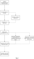
- Fig. 2 shows an algorithm of the method step according to the present invention.
- a gear is provided.
- the gear is manufactured by additive manufacturing method known to the skilled person in the art.
- Material of the gear is stainless steel.
- the material can be austenitic 316L stainless steel, ferritic stainless steel or martensitic stainless steel.
- the gear can be pre-characterized on residual stresses, surface roughness, scanning electron microscopy, micro-geometry.
- the gear manufactured by additive method is usually fragile and does not achieve the material properties of macroscopic gears. Hence, such a gear needs to be further treated so that it acquires the properties that are characteristic of macroscopic gears.
- the gear is at least partially immersed in the water pool, so that the part to be treated by the laser shock peening is immersed in a depth of 5 - 10 cm below the water surface. It is advantageous to use a robotic arm for immersing the gear.
- the water can be a state of the art de-ionised water and does not require any special condition.
- the laser is set to the empirically observed parameter, which provides sufficient compression stress below the surface of the gear, while the gear preserve its structural integrity without any observable damage.
- the laser is set to: laser pulse having energy between 200 mJ and 1 J, setting pulse duration of the beam to value between 10 ns and 15 ns, setting repetition rate from 1 Hz - 15 Hz, and setting density of the laser beam is between 1,7 GW/cm 2 and 8,49 GW/cm 2 .
- the laser beam is calibrated with diagnostic system, such as photodiode, energy meter, CCD camera for laser profile.
- the robotic arm is turned on and connect with the laser source so that laser can be controlled from the robotic arm.
- the laser beam is than focused to specific part of the mesoscopic gear, in particular to a root along a fillet radius and space between two teeth of the gear.
- Fig. 3 discloses a detail of the laser shock peening applied on the root along a fillet radius and space between.
- Laser beam 104 is focused on the space 103 between teeth 101 and 102.
- Dotted line represents the line of the laser beam application, i.e. the introduction of the residual stress introduced by the laser shock peening.
- the laser beam path can be aligned from the laser source to the gear.
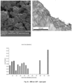
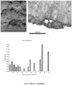
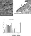
- Figure 6-7 presents the SEM and electron backscattered diffraction (EBSD) images for the unpeened samples and LSPeened samples at different energies.
- Fig. 6-7 also depicts the grain size distribution obtained through microscopy for the unpeened samples and LSPeened samples at different energies. It can be observed while comparing the surface morphology that LSP has successfully altered the microstructure in terms of grain size and redefined the grain boundaries for both the gear geometries. The changes in the microstructures after LSP were one of the prime movers in improving the mechanical properties such as compressive residual stresses.
- the grain size analysis has been performed based on the grain size distribution on all three samples for 1 mm depth from the top on the ridge of the sample.
- the grains under 50 ⁇ m is considered fine grains, whereas the size of grains in the range of 50-100 ⁇ m and above 100 ⁇ m is deemed to be medium and large size grains, respectively. It has been observed that the majority of the grains in the unpeened sample was in the range of medium to large grains, whereas the effect of peening was visible in both the types of geometries i.e. spur and helical gear samples where the grain sizes were in the refined to fine to medium grains. Most of the substantial grains, i.e., 70 ⁇ m and above, visible in the unpeened sample, were eliminated after LSP.
- Fig. 8 further discloses the distribution of residual stresses introduced to the gear in accordance with above-mentioned examples.
- the unpenned gear shows positive residual stress in both, spur and helical gear.
- negative residual stress compression
- the negative stress ranges from -430 MPa to -100 MPa.
- Particular improvement of the surface morphology is shown on the Fig. 6 and 7 .
- the compression ranges from -300 MPa to -100 MPa.
- the compression ranges from - 430 MPa to - 230 MPa.
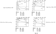
- Fig. 10 shows particular parameters of material distribution. The comparative study is shown among referenced unpenned gear, the spur gear and helical gear after peening.
- Vmp stands for peak material volume
- Vmc stands for core material volume
- Vvc stands for core void volume
- Vvv stands for valley void volume. All of the above-mentioned parameters corresponds to the well-known Abbott-Firestone curve.
Landscapes
- Engineering & Computer Science (AREA)
- Physics & Mathematics (AREA)
- Optics & Photonics (AREA)
- Mechanical Engineering (AREA)
- Plasma & Fusion (AREA)
- Chemical & Material Sciences (AREA)
- Manufacturing & Machinery (AREA)
- Materials Engineering (AREA)
- Robotics (AREA)
- Thermal Sciences (AREA)
- Crystallography & Structural Chemistry (AREA)
- Metallurgy (AREA)
- Organic Chemistry (AREA)
- Laser Beam Processing (AREA)
- Gears, Cams (AREA)
Description
- The present invention relates to a method of post-manufacturing treatment of a 3D-printed product. More particularly, the present invention relates to post-manufacturing treatment by laser shock peening applied on a gear printed on a 3D printer. Even more particularly, the invention relates to post-manufacturing laser shock peening of a gear having a size between 1 mm to 10 mm.
- The second aspect of the present invention relates to a gear having a size between 1 mm and 10 mm, so called mesoscopic gear, being treated by laser shock peening to provide increased lifetime service.
- Gears are used in various industrial and technological applications to permit power transmission from one rotating or translating element to another. Each gear generally includes an array of gear teeth that mesh with the gear teeth of another gear so that the rotation or translation of the first gear can be transmitted to the second. The forces on the gear teeth over time may cause failure of the gear, i.e. end of life of the gear. Therefore, there is a demand to improve the quality of the gear and extend service life.
- 3D printing is a known method for component manufacturing made of wax or any suitable thermoplastic, such as a plastic toy. However, the 3D printing method for mechanical industry or construction is not yet well established. The mechanical components require long-term reliability and mechanical resilience, which, due to the nature of the method, cannot always be guaranteed. 3D-printing is also known as additive manufacturing. In additive manufacturing, a component is created by adding material, unlike milling, which removes material from a structural part. The material, in the case of the mechanical industry, should be a steal or similar material having similar properties. Currently, there are only a few available methods for additive manufacturing of steel, which usually requires selective laser melting and selective laser sintering. Another method of steel additive manufacturing is directed to laser metal deposition, in which a metal powder is applied to a local molten pool provided by the laser. The main limitation of a product built by the additive manufacturing in the mechanical industry is its inadequate mechanical properties compared to conventionally produced products. The main limitation is the result of tensile residual stresses (TRS), increased surface roughness, and lower part density.
- Laser shock peening (LSP) is a well-known process that uses high-intensity laser pulses to generate deep compressive residual stresses. Standard LSP can be performed with laminar water flow over the surface of the component. The surface is also covered with an absorption layer that both absorbs the laser pulse and protects the underlying substrate from heat effects. The absorbent coating local to the laser impingement becomes plasma that is constrained by the component and water layer. A pressure pulse is thus created which propagates as a shock wave deep into the material and generates compressive residual stresses.
- There exists macroscopic gear defined as the gear having the size more than 10-12 mm. The microscopic gears are having the size less than 1 mm and Mesoscopic gear have size in the range of 1 mm to 10 mm.
- The method of additive manufacturing by means of selective laser melting and laser shock peening as the post-processing is described in
US2017087670 . The document discloses application of laser shock peening during the steps of additive manufacturing. The proposed solution, however, requires additional requirements on timing of the laser beams used for laser melting and laser shock peening. - There is a demand for a gear printed on a 3D printer from certain type of material, such as stainless steel.
-
US10619222 - Thus, the object of the present invention is to provide a method for improving service life of the gear having outside diameter between 1 mm and 10 mm, wherein the gear is made of stainless steel by additive manufacturing.
- Document
WO2018156143 discloses a three-dimensional printing method which, for example, allows to form a part in the form of a gear. - The article "Laser shock peening without coating induced residual stress distribution, wettability characteristics and enhanced pitting corrosion resistance of austenitic stainless steel"; S. Prabhakaran et al.; Applied Surface Science 428 (2018) 17-30; discloses a low energy laser shock peening without coating on AISI 304 austenitic stainless steel specimens.
- The present invention is defined by the independent claims. Advantageous embodiments are described in dependent claims.
- The above mentioned problem is solved by the present invention. In a first aspect, a method for improving surface integrity, therefor improving service life, of an additive manufactured gear having size from 1 mm to 10 mm is provided. The method comprises the steps of:
- providing a gear made of stainless steel by additive manufacturing;
- immersing the gear into a water pool; wherein at least a part of the gear intended for post manufacturing processing is completely immersed in static water; and wherein the gear is placed within the water, preferably with the help of a robotic arm, at a distance ranging from 5 cm to 10 cm from the laser beam source;
- setting a laser beam for laser shock peening; wherein the step of setting comprises: setting laser pulse having energy between 200 mJ and 1 J, setting pulse duration of the beam to value between 10 ns and 15 ns, setting repetition rate from 1 Hz - 15 Hz, and setting density of the laser beam is between 1,7 GW/cm2 and 8.49 GW/cm2;
- applying the laser shock peening to a root along a fillet radius in a gap between two neighbouring teeth of the gear immersed in the water, wherein
- the laser shock peening is applying directly to the surface of the gears without protective taping or coating; and wherein
- the spot size of the laser beam is substantially the same as the size of the gap, and wherein the irradiated stop sizes are overlapping for at least 90% of the area.
- The above mentioned method provides an improvement in service life. In particular, the application of laser shock peening imparts the compressive residual stresses in the root, fillet radius, and space between the two teeth of the gears. Microstructure, residual stresses and surface roughness have been improved in terms of average surface roughness Ra and peak material volume Vmp. Particular improvement is connected to fatigue of the gear. Fatigue is defined as a process of progressive localized plastic deformation occurring in a material subjected to cyclic stresses and strains at high stress concentration locations that may culminate in cracks or complete fracture after a sufficient number of fluctuations.
- Laser shock peening was performed without affecting the geometry of the gear tooth's face width, top land, and pitch. Furthermore, improved residual stresses, improved surface roughness and no alteration in the dimensional mesoscopic-geometry have been observed, which due to the size of the gear is advantageous.
- Better surface morphology, in particular, low level of applied energy of the laser beam ranging from 200 mJ to 1 J eliminates the need for high-power lasers, thus making the processing cost effective and suitable to be implemented by the state of the art laser device. Synergetic effect provided by the combination of energy and density of the laser beam as mentioned above provides the advantage of not using tape during LSP.
- The size of the gear is hereby referred to distance between two teeth on opposite sides of the gear, i.e. outer diameter of the gear. There is no limit to the width of the gear, which can be more than 10 mm. Preferably, the width of the gear is substantially the same as the diameter of the gear. The size of the sub-parts, such as the size of a disc - inner diameter; the size of the teeth - for example circular pitch, circular thickness, face width, addendum, dedendum, chordal pitch; the size of the shaft hole - inner diameter; the chamfer or roundness at the root between the teeth; the chamfer angle of the helical gears are not limitation according to the present invention. In some embodiment, high of the teeth gear can be several millimetres, e.g. 2 mm, which can be mechanically damages when state of the art method of hardening is applied. The conditions of laser shock peening as claimed on the gear provides superior fatigue life and strength.
- The stainless steel can be austenitic 316L stainless steel, which provides corrosion resistance, ductility, and biocompatibility. The austenitic steel 316L has low strength and wear resistance, limiting its high-performance applicability. However, due to the application of laser shock peening, the steel is plastically compressed and surface properties are improved. In another embodiment, the steel can be ferritic stainless steel or martensitic stainless steel. The method according to the present invention is applicable to any of stainless steel, independently of specific alloy, manufactured by means of additive manufacturing.
- The additive manufacturing is a process of joining materials to make parts from 3D model data, usually layer upon layer, as opposed to subtractive manufacturing and formative manufacturing methodologies There are numerous ways in which units of material can be joined together to form a part. Different types of materials are being held together by different types of atomic bonds, in particular metallic materials, such as stainless steel, are typically held together by metallic bonds. For additive manufacturing processes, the feedstock, the bulk raw material that is fed into the process, can typically come in the form of powder (dry, paste or slurry), also in the shape of un-cured liquid material. Dependent on the shape, the feedstock may then be distributed layer by layer in a powder bed, deposited by a nozzle, applied as layers in a sheet stack, deposited through a print head, or applied as a liquid, paste or slurry in a vat. In respect to the great possibilities for variation in different types of materials, different types of feedstock and means of distribution of the feedstock, there is large number of possible principles that could be used for additive manufacturing processes. In some embodiment, the additive manufacturing can use of various advanced techniques, including electron beam melting and laser-based powder bed fusion (LPBF), commercially known as selective laser melting (SLM) or direct metal laser sintering (DMLS). In some embodiment, suitable material compatible with the method of additive manufacturing can be the austenitic nickel-chromium-based class, such as Inconel, and martensitic steel alloys. The preferred embodiment of the present invention aims to harness the potential of 3D printing to optimize the characteristics of these alloys for various demanding applications, including aerospace, defense, energy extraction, and more, with the post-processing manufacturing treatment by the laser shock peening. The alloy manipulation can involve precise control over crystallographic texture, solidification structure, and microstructure, thereby enhancing the final properties of the produced metal parts. However, for post-processing method according to the present invention, the characteristics of the additively manufactured mesoscopic gears are not the essential features and the invention can be used for any-type of the mesoscopic gears manufactured by any suitable method. In a more preferred embodiment, the step of additive manufacturing can comprise alloy selection, which can comprises the steps identifying and choosing suitable alloys, such as Inconel and martensitic steel alloys, based on their intended application and required properties. In another embodiment, suitable method can be Electron Beam Melting (EBM) Process, which employ an ARCAM electron beam melting system or a similar apparatus to carry out the 3D printing process. EBM process can selectively melt the alloy powder, allowing the controlled design of the crystallographic texture and solidification structure of the metal part. In another preferred embodiment, a Laser-Based Powder Bed Fusion (LPBF) Process can be used. Implementing LPBF, specifically selective laser melting (SLM) or direct metal laser sintering (DMLS), can be used to achieve additive manufacturing. A digital computer model can guide the precise location where a high-energy laser beam selectively melts and fuses the alloy powder. The embodiments are only the examples of the method of additive manufacturing. The method according to the present invention, however, is applicable to any stainless steel manufactured by means of additive manufacturing, independently on the actual steps of additive manufacturing.
- Once the gear is produced by the additive manufacturing process, it is immersed in a water pool for LSP processing. Depending on the size of the gear, only the part of the gear that needs to be treated with LSP can be immersed in the water pool with no flowing water around it, thereby static water. In flowing water the cavitation is prevalent phenomenon which may lead to detrimental effect on the interacting surface. The application of immersed water was used because of the static condition of the water, liquid replenishment occurs immediately before the second pulse interacts with the surface, which protects the interacting surface from any detrimental thermal effects. This gives scope for pulse overlap LSP without the need to use any protective layer nor coating. It is not necessary to submerge the entire gear under the water surface. Preferably, a robotic arm can be used to submerge the gear below the water surface to place the gear at a precisely positioned distance below the water surface. It is also advantageous to use the robotic arm in terms of automation and speed of treatment of the laser shock peening. The gear is placed 5 to 10 cm below the water surface, this distance being empirically determined for the laser shock peening treatment given the laser parameter.
- The place of applying the laser shock peening to the gear is specific. They are a root along a fillet radius and space between two teeth. It is at these points that the gear is most stressed and requires reinforcement. Due to the laser parameters set as mentioned above, the laser beam can be applied directly to the specific surface of the gear without any protective layer nor coating. The size of the spot corresponds to the gap between two neighbouring teeth. Furthermore, it was empirically observed that the spots of the beam, when laser shock peening is applied, is at least 90% to achieve improvement on the surface mechanical properties.
- In a preferred embodiment, the method further comprising aligning the laser beam path from a laser source to the gear.
- In another preferred embodiment, the method further comprising calibrating diagnostics of the laser source, in particular calibrating photodiode, energy meter, CCD camera for laser profile.
- In another preferred embodiment, the method further comprising controlling the laser beam for laser shock peening by the robotic arm.
- In another preferred embodiment, the method wherein the step of providing the gear and applying the laser shock peening is providing a helical gear and applying the laser shock peening on the helical gear. Helical gear is a species of the general gear, wherein the teeth are cut at an angle to the hole (axis) rather than straight and parallel to the hole like the teeth of a spur gear. Applying the laser beam to the area between the teeth is problematic with the helical gears. In particular, the problematic part of the application lies in the need to change the position of the beam with respect to the changing angle at the tooth root depending on the position. At the same time, at least 90% overlap must be maintained. It is especially advantageous to combine the embodiment with an adaptive laser beam alignment.
- In another aspect of the present invention, an additive manufactured gear made of stainless steel is provided. Such the mesoscopic gear can be preferably manufactured by the method according to the present invention. The additive manufactured gear made of stainless steel having size from 1 mm to 10 mm comprising plurality of teeth. Pressure angle in relation to the gear teeth can be within the range known to the skilled person in the art. Residual stress introduced in the gear by laser shock peening is negative. Arithmetic mean height on the gear surface is up to 40 µm. Number of grains having size less than 50 µm is greater than the number of grains having size greater than 50 µm in any selected area treated by laser shock peening.
- Pressure angle in relation to gear teeth, also known as the angle of obliquity, is the angle between the tooth face and the gear wheel tangent. It is more precisely the angle at a pitch point between the line of pressure (which is normal to the tooth surface) and the plane tangent to the pitch surface. I accordance with the present invention, the angle is within the range known to the skilled person in the art.
- Residual stress introduced in the gear by laser shock peening is negative. In a mathematical sense the term compressive residual stress refers to a negative residual stress. The compression is introduced into the material, nearby it's surface, via the laser shock peening. The compression redistributes the pressure over the surface of the root of gear. Since the residual stresses are also distributed over the gear surface, the surface layer properties produced by the laser shock peening directly affects part performance, including fatigue strength, wear behaviour, and chemical resistance. In a preferred embodiment, a method for measuring residual stress induced by laser shock peening and during the application of laser shock peening on the mesoscopic gear and/or before and after the application of laser peening on the mesoscopic gear is disclosed. The preferred method for residual stress monitoring and/or measurement leverages X-ray diffraction as an indirect means of quantifying strain within the material. The interaction between X-ray beams and the crystal lattice is harnessed in accordance with Bragg's Law, allowing for the precise determination of the diffraction peak's location, denoted as θ. The changes in the θ are small (in the range of tenths of a degree). If the 2θ angles are plotted against the (sin2ψ), where Ψ is an angle made between sample surface normal and lattice plane normal, the relationship is linear. From the fitted line, its slope is evaluated. If there is a rising tendency the measured stress is in compressive region. For the case of line being horizontal, the stress is zero and if the line is going down the stress is positive, i.e tensile. Preferably, during the measurement process, variations in the θ angle are observed. This distinct correlation serves as an indicator of strain magnitude, specifically highlighting regions characterized by compressive stress. Notably, when this observed correlation is established, the resultant measurement values are conventionally considered negative, aligning with established practices in stress analysis. Since the residual stresses on the sample can be tested before laser shock treatment with X-ray diffractometry on the same location and measured in the same way after laser shock treatment, a skilled person can deduce by comparing that the negative stresses were introduced by the laser shock treatment.
- In a preferred embodiment, the present invention pertains to test methods for the determination of grain size. The preferred method can include the comparison procedure, planimetric (or Jeffries) procedure, and intercept procedures. For the purposes of the preferred test methods, the term "grain" refers to an individual crystal possessing consistent atomic configuration throughout a polycrystalline material. Notably, a grain may encompass twinned regions or sub-grains. The three steps for grain size estimation can comprises the comparison procedure, that eliminates the need for direct counting of grains, intercepts, or intersections. This step entails contrasting the grain structure with a sequence of graded images. Such images can be presented through mediums like wall charts, clear plastic overlays, or an eyepiece reticle. The planimetric step can necessitate a direct count of the number of grains within a known area. The intercept step can involve directly counting the number of grains intercepted by a test line or the number of intersections between grain boundaries and a test line. This count is measured per unit length of the test line and is utilized in calculating the mean lineal intercept length. Preferably, the method of grain size determination can be utilized by computer software, such as EDAX APEX 2.5 software and EBSD map were evaluated with EDAX OIM 8.6 software, wherein grain size diameter were evaluated using weighing by grain area. More preferably, the grain size are determined by publicly available ASTM E112-13 (Updated: Nov 17, 2021) standard.
- In a preferred embodiment, the measurement of surface roughness can be achieved using contact profilometry, a well-established technique involving the use of a stylus or diamond-tipped probe. The stylus can be systematically dragged across the metallic surface, and its vertical displacement along the scan path can be recorded. The resulting height variations can calculate the roughness parameters Ra (average surface roughness). The contact profilometry method can be used for its exceptional accuracy and versatility in surface roughness measurement. In another embodiment, the invention employs non-contact optical profilometry techniques to measure surface topography without physical contact with the metallic surface. Techniques like white light interferometry and confocal microscopy can be used to generate high-resolution 3D images, offering precise measurement of roughness parameters. In another preferred embodiment, an Atomic Force Microscopy (AFM), a powerful nanoscale imaging technique, can be used for surface roughness evaluation. The AFM can utilize a sharp cantilever with a nanoscale tip to scan the metallic surface, detecting forces between the tip and the surface. This allows for ultra-high-resolution 3D imaging, enabling the measurement of roughness parameters at the nanometer scale. The AFM technique is particularly advantageous when assessing nanostructured metallic surfaces.
- In a preferred embodiment, the compressive residual stress ranges from -430 MPa to -100 MPa.
- In another preferred embodiment, peak material volume is from 1,55 µm3/µm2 to 1,62 µm3/µm2; and core material volume is from 24,6 µm3/µm2 to 25,1 µm3/µm2 ; core void volume is from 41 µm3/µm2 to 48 µm3/µm2 ; and valley void volume is from 1,63 µm3/µm2 to 2,21 µm3/µm2.
- In a preferred embodiment, the gear is a helical gear or a spur gear.
- The helical gear is preferably provided with the residual stress ranging from -430 MPa to -230 MPa. In another preferred embodiment of the helical gear embodiment, average surface roughness is at least 10.
- The spur gear has preferably residual stress introduced by LSP from -300 MPa to -100 MPa.
-
-
Fig. 1 represents a schematic drawing of a mesoscopic spur gear and helical gear for LSP application. -
Fig. 2 represents a method steps according to the present invention. -
Fig. 3 represents parts of a gear for laser shock peening (LSP) application. -
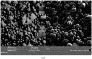
Fig. 4 represents an image of flat base material before LSP provided by electron backscatter diffraction. -
Fig. 5a and 5b represent images for a mesoscopic gear according to the present invention after LSP -
Fig. 6a-6f represents a comparative images of the surface of the mesoscopic spur gear according to the present invention with respect to energy of the laser beam. -
Fig. 7a-7f represents a comparative images of the surface of the mesoscopic helical gear according to the present invention with respect to energy of the laser beam. -
Fig. 8 represents residual stress distribution in the spur and helical gear treated by the method according to the present invention. -
Fig. 9 represents particular arithmetic mean height and average surface roughness for the spur and helical gear. -
Fig. 10 represents parameters of material distribution in the referenced unpenned gear, spur and helical gears. -
Fig. 1 schematically shows two preferred embodiments of a gears, a spur gear and a helical gear.Fig. 1a and 1b shows a spur gear andFig. 1c and 1d shows a helical gear. The skilled person in the art, however, may recognize that the present invention can be implemented into any of the state of the art gear within mesoscopic size.Fig. 1 schematically shows sizes of the gear. In particular, d1 refers to a distance between two teeth on opposite sides of the gear, i.e. diameter of the gear. The parameter d1 is within 1 mm to 10 mm to be classified as the mesoscopic gear. Parameter d2 refers to a distance between twoneighbouring teeth -
Fig. 2 shows an algorithm of the method step according to the present invention. In a first step, a gear is provided. The gear is manufactured by additive manufacturing method known to the skilled person in the art. Material of the gear is stainless steel. The material can be austenitic 316L stainless steel, ferritic stainless steel or martensitic stainless steel. The gear can be pre-characterized on residual stresses, surface roughness, scanning electron microscopy, micro-geometry. The gear manufactured by additive method is usually fragile and does not achieve the material properties of macroscopic gears. Hence, such a gear needs to be further treated so that it acquires the properties that are characteristic of macroscopic gears. In the next step, the gear is at least partially immersed in the water pool, so that the part to be treated by the laser shock peening is immersed in a depth of 5 - 10 cm below the water surface. It is advantageous to use a robotic arm for immersing the gear. The water can be a state of the art de-ionised water and does not require any special condition. In the next step, the laser is set to the empirically observed parameter, which provides sufficient compression stress below the surface of the gear, while the gear preserve its structural integrity without any observable damage. The laser is set to: laser pulse having energy between 200 mJ and 1 J, setting pulse duration of the beam to value between 10 ns and 15 ns, setting repetition rate from 1 Hz - 15 Hz, and setting density of the laser beam is between 1,7 GW/cm2 and 8,49 GW/cm2. In a preferred embodiment, the laser beam is calibrated with diagnostic system, such as photodiode, energy meter, CCD camera for laser profile. Preferably, the robotic arm is turned on and connect with the laser source so that laser can be controlled from the robotic arm. The laser beam is than focused to specific part of the mesoscopic gear, in particular to a root along a fillet radius and space between two teeth of the gear. The above-mentioned setting introduces to the stainless steel compressive pressure via laser shock peening. The gear is provided without protective taping nor coating so that the laser beam is applied directly on the surface of the gear. The laser beam is provided with the spot size, which is substantially about the size of thegap 103, resp. 203, between twoneighbouring teeth -
Fig. 3 discloses a detail of the laser shock peening applied on the root along a fillet radius and space between.Laser beam 104 is focused on thespace 103 betweenteeth - In a first example according to the present invention, a mesoscopic spur gear having the size shown in table 1 has been manufactured by means of additive manufacturing. The selective laser melting has been used as an additive manufacturing technique; the details of parameters used to print the gears are presented in table 2. The gear was designed with module 0.8 and number of teeth as 10 for both spur and helical geometry. While the pressure angle for both the geometries was chosen a 20 ° and helix angle for helical gear was 20 °.
- Laser Shock Peening (LSP) was applied by using a solid state diode pumped laser system with a laser source was a Nd:YAG - a pulsed laser having pulse duration of upto 15 ns, operating at 1064 nm. The beam spatial energy distribution is "top-hat" and the pulse shape is near - Gaussian. Round laser spots of 1 mm diameter were used with a laser energy per pulse in the range of 200 mJ to 1 J, whereas the laser device has capacity of maximum energy as 3 J. The ratio of spot size and energy per pulse was chosen such as to keep a power density for the present work in the range of 1.7 to 8.49 GW/cm2. The advantage in using lower energies per pulse (for a given power density) is observed as to secure that the profile of the gears will not differ from the original and at the same time to impart compressive residual stresses.
- The laser shock peening was applied to mesoscopic spur and helical gear in the filler area and the root, the spot size of the laser beam i.e. 1 mm is selected in such a way that it covers the root and fillet gap and does not affect the flank surface of the gears as schematically shown on
Fig. 3 . - The pressure created at the surface of the part was estimated to maximum of 5 GPa using the energy in the range of 200 mJ to 1J, with pulse frequency of 15 Hz and the overlap of 90 % was used for spot size of 1 mm without a protective ablative layer.
- Residual stresses measurements were done with XRD measurements, the cathode source used for the measurement was chromium (Cr) radiation (Kα=2.29103 Å) at 40 kV and 40 mA. To analyse the manufactured gears with SLM Face centred structured (220) diffraction peak was used.
- Preferably, the laser beam path can be aligned from the laser source to the gear.
- Preferably, the method comprises calibrating photodiode, energy meter, CCD camera for laser profile.
- In a second example according to the present invention, a mesoscopic helical gear having the size shown in table 1 has been manufactured by means of additive manufacturing.
- Laser Shock Peening (LSP) was applied done using the laser device. The laser source was a Nd:YAG. The beam spatial energy distribution is "top-hat" and the pulse shape is near - Gaussian. Round laser spots were used with a laser energy per pulse of either. The ratio of spot size and energy per pulse was chosen such as to keep a constant power density.
- The pressure created at the surface of the part was estimated to maximum of 5 GPa using the energy in the range of 200 mJ to 1J, with Pulse frequency of 15 Hz and the overlap of 90 % was used for spot size of 1 mm without a protective ablative layer.
- Residual stresses measurements were done with XRD measurements, the cathode source used for the measurement was chromium (Cr) radiation (Kα=2.29103 Å) at 40 kV and 40 mA. To analyse the manufactured gears with SLM Face centred structured (220) diffraction peak was used.
Table 1 Parameters Spur gear Helical gear number of teeth 10 10 normal module 0.8 0.8 transverse module 0.8 0.85 pressure angle (degree) 20 20 transverse pressure angle (degree) 20 21.17 helix angle (degree) 0 20 addendum diameter (mm) 9.6 10 pitch circle diameter (mm) 8 8.5 base circle diameter (mm) 7.5 7.9 root diameter (mm) 6 6.3 tooth thickness (mm) 1.25 1.21 bore diameter (mm) 4 4 height of hub (mm) 5 5 hub outer diameter (mm) 6 6 -
Table 2 Slice thickness: 0,02 mm Laser focus diameter: 0,055 mm Laser speed: 675 mm/sec Laser Power: 150 W Hatch distance: 0,1 mm -
Fig. 4 depicts the SEM image of the flat plate printed of the stainless steel materials manufactured using the SLM, where we can see that there are several unfused particles visible and thus leads to have poor surface morphology. WhereasFig. 5a and 5b present the photograph of the manufactured spur and helical gears by method of additive manufacturing mounted under SEM before (left part) and after (right part) LSP. It is observable that the left parts of the figures, which correspond to the unpenned gears, contain highly porous surface. After LSP treating in accordance with present invention, the surface is flat and the porous character of the gear was diminished. -
Figure 6-7 presents the SEM and electron backscattered diffraction (EBSD) images for the unpeened samples and LSPeened samples at different energies.Fig. 6-7 also depicts the grain size distribution obtained through microscopy for the unpeened samples and LSPeened samples at different energies. It can be observed while comparing the surface morphology that LSP has successfully altered the microstructure in terms of grain size and redefined the grain boundaries for both the gear geometries. The changes in the microstructures after LSP were one of the prime movers in improving the mechanical properties such as compressive residual stresses. The grain size analysis has been performed based on the grain size distribution on all three samples for 1 mm depth from the top on the ridge of the sample. The grains under 50 µm is considered fine grains, whereas the size of grains in the range of 50-100 µm and above 100 µm is deemed to be medium and large size grains, respectively. It has been observed that the majority of the grains in the unpeened sample was in the range of medium to large grains, whereas the effect of peening was visible in both the types of geometries i.e. spur and helical gear samples where the grain sizes were in the refined to fine to medium grains. Most of the substantial grains, i.e., 70 µm and above, visible in the unpeened sample, were eliminated after LSP. -
Fig. 8 further discloses the distribution of residual stresses introduced to the gear in accordance with above-mentioned examples. The unpenned gear shows positive residual stress in both, spur and helical gear. On the other hand, after the application of the method according to the present invention, negative residual stress (compression) was introduced to the gear. The negative stress ranges from -430 MPa to -100 MPa. Particular improvement of the surface morphology is shown on theFig. 6 and7 . In the example relating to spur gear, the compression ranges from -300 MPa to -100 MPa. In the example of helical gear, the compression ranges from - 430 MPa to - 230 MPa. -
Fig. 9 shows particular arithmetic mean height and average surface roughness for the spur and helical gear according to the example above. -
Fig. 10 shows particular parameters of material distribution. The comparative study is shown among referenced unpenned gear, the spur gear and helical gear after peening. Vmp stands for peak material volume, Vmc stands for core material volume, Vvc stands for core void volume, Vvv stands for valley void volume. All of the above-mentioned parameters corresponds to the well-known Abbott-Firestone curve.
Claims (13)
- A method for improving surface integrity of a gear made of stainless steel by an additive manufacturing method, wherein the gear having distance between two teeth on opposite sides of the gear from 1 mm to 10 mm comprising- providing the gear made of stainless steel by additive manufacturing;- immersing the gear into a water pool so that the part to be treated by the laser shock peening is immersed in a depth of 5-10 cm below the water surface;- setting a laser beam for laser shock peening; wherein the step of setting comprising setting laser pulse having energy between 200 mJ and 1 J, setting pulse duration of the beam to value between 10 ns and 15 ns, setting repetition rate from 1 Hz - 15 Hz, and setting density of the laser beam is between 1,7 GW/cm2 and 8,49 GW/cm2;- applying the laser shock peening to a root along a fillet radius in a gap (103 or 203) between two neighbouring teeth (101 and 102), wherein- the laser shock peening is applying directly to the surface of the gears without protective taping nor coating; and wherein- the spot size of the laser beam is substantially the same as the size of the gap, and wherein the irradiated spot sizes are overlapping for at least 90% of the area.
- The method according to claim 1 further comprising aligning the laser beam path from a laser source to the gear.
- The method according to claim 1 or 2 further comprising calibrating diagnostics of the laser source, in particular calibrating photodiode, energy meter, CCD camera for laser profile.
- The method according to anyone of the previous claim further comprising controlling the laser beam for laser shock peening by the robotic arm.
- The method according to anyone of the previous claim, wherein the step of providing the gear and applying the laser shock peening is providing a helical gear and applying the laser shock peening on the helical gear.
- An additive manufactured gear made of stainless steel having distance between two teeth on opposite sides of the gear from 1 mm to 10 mm comprising plurality of teeth obtainable by the method according to anyone of the claims 1 to 6, characterized in that,residual stress introduced by laser shock peening is negative, wherein the residual stress is measured by the method described in [026]; and whereinarithmetic mean height on the surface, measured by a method described in [028], is up to 40 µm; and wherein number of grains having size less than 50 µm is greater than the number of grains having size greater than 50 µm in any selected area treated by laser shock peening, wherein the grain size is measured by the method described in [027].
- The additive manufactured gear according claim 6, wherein the residual stress ranges from -430 MPa to -100 MPa, measured by the method described in [028].
- The additive manufactured gear according claim 6 or 7, wherein peak material volume is from 1,55 µm3/µm2 to 1,62 µm3/µm2; and core material volume is from 24,6 µm3/µm2 to 25,1 µm3/µm2 ; core void volume is from 41 µm3/µm2 to 48 µm3/µm2 ; and valley void volume is from 1,63 µm3/µm2 to 2,21 µm3/µm2.
- The additive manufactured gear according to claim 6 or 7, wherein the gear is a helical gear.
- The additive manufactured gear according to claim 9, wherein the residual stress ranges from - 430 MPa to -230 MPa.
- The additive manufactured gear according to claim 9 or 10, wherein average surface roughness Ra is at least 10, wherein the average surface roughness is preferably measured by contact profilometry or non-contact optical profilometry or by atomic force microscopy.
- The additive manufactured gear according to claim 6 or 7, wherein the gear is a spur gear.
- The additive manufactured gear according to claim 12, wherein the residual stress ranges from - 300 MPa to -100 MPa.
Applications Claiming Priority (1)
| Application Number | Priority Date | Filing Date | Title |
|---|---|---|---|
| LU502626A LU502626B1 (en) | 2022-08-04 | 2022-08-04 | Method for improving surface integrity of an additive manufactured mesoscopic gear, product thereof and device carrying out the method |
Publications (3)
| Publication Number | Publication Date |
|---|---|
| EP4316693A1 EP4316693A1 (en) | 2024-02-07 |
| EP4316693B1 true EP4316693B1 (en) | 2025-07-02 |
| EP4316693C0 EP4316693C0 (en) | 2025-07-02 |
Family
ID=83546793
Family Applications (1)
| Application Number | Title | Priority Date | Filing Date |
|---|---|---|---|
| EP23189717.4A Active EP4316693B1 (en) | 2022-08-04 | 2023-08-04 | Method for improving surface integrity of an additive manufactured mesoscopic gear, and product thereof |
Country Status (4)
| Country | Link |
|---|---|
| US (1) | US20240042551A1 (en) |
| EP (1) | EP4316693B1 (en) |
| LU (1) | LU502626B1 (en) |
| WO (1) | WO2024027863A1 (en) |
Families Citing this family (2)
| Publication number | Priority date | Publication date | Assignee | Title |
|---|---|---|---|---|
| CN121082914A (en) * | 2025-11-12 | 2025-12-09 | 湖南珞佳增材制造有限公司 | 4D printing system and method based on cross-space-time scale in-situ real-time monitoring regulation and control |
| CN121945964B (en) * | 2026-04-01 | 2026-06-12 | 中南大学 | A method and apparatus for ultrasonic-assisted laser processing of microtextured tooth surfaces |
Family Cites Families (5)
| Publication number | Priority date | Publication date | Assignee | Title |
|---|---|---|---|---|
| US10619222B2 (en) | 2015-04-08 | 2020-04-14 | Metal Improvement Company, Llc | High fatigue strength components requiring areas of high hardness |
| EP3147048B1 (en) | 2015-09-28 | 2020-08-05 | Ecole Polytechnique Federale De Lausanne (Epfl) | Method and device for implementing laser shock peening (lsp) or warm laser shock peening (wlsp) during selective laser melting (slm) |
| KR102231843B1 (en) * | 2017-02-24 | 2021-03-24 | 휴렛-팩커드 디벨롭먼트 컴퍼니, 엘.피. | Three-dimensional (3D) printing method |
| JP7144234B2 (en) * | 2018-08-20 | 2022-09-29 | 株式会社Subaru | Laser peening processing device and laser peening processing method |
| AT523693B1 (en) * | 2020-03-24 | 2022-06-15 | Miba Sinter Austria Gmbh | Process for manufacturing a three-dimensional component |
-
2022
- 2022-08-04 LU LU502626A patent/LU502626B1/en active IP Right Grant
-
2023
- 2023-08-04 US US18/365,217 patent/US20240042551A1/en active Pending
- 2023-08-04 EP EP23189717.4A patent/EP4316693B1/en active Active
- 2023-08-04 WO PCT/CZ2023/050048 patent/WO2024027863A1/en not_active Ceased
Also Published As
| Publication number | Publication date |
|---|---|
| WO2024027863A1 (en) | 2024-02-08 |
| US20240042551A1 (en) | 2024-02-08 |
| EP4316693C0 (en) | 2025-07-02 |
| EP4316693A1 (en) | 2024-02-07 |
| LU502626B1 (en) | 2024-02-07 |
Similar Documents
| Publication | Publication Date | Title |
|---|---|---|
| Boban et al. | Improving the surface integrity and mechanical properties of additive manufactured stainless steel components by wire electrical discharge polishing | |
| EP4316693A1 (en) | Method for improving surface integrity of an additive manufactured mesoscopic gear, and product thereof | |
| Pineault et al. | X-ray diffraction residual-stress measurement in failure analysis | |
| Wanjara et al. | Titanium alloy repair with wire‐feed electron beam additive manufacturing technology | |
| Aversa et al. | Effect of heat treatments on residual stress and properties of AISI 316L steel processed by directed energy deposition | |
| Pan et al. | Experiment characterization and formulation estimation of tensile properties for selective laser melting manufactured 304L stainless steel | |
| Yadroitsava et al. | Residual stress in metal specimens produced by direct metal laser sintering | |
| Okuniewski et al. | Effect of surface modification by shot peening on cavitation erosion resistance of titanium alloy Ti-6Al-4V produced by DMLS method | |
| Haribaskar et al. | The impact of successive laser shock peening on surface integrity and residual stress distribution of laser powder-bed fused stainless steel 316L | |
| Nino-Barrera et al. | Shot peening increases resistance to cyclic fatigue fracture of endodontic files | |
| Parikh et al. | Property-graded stainless steel 316L by selective laser melting: characterization & design | |
| Lesyk et al. | Laser-based additive manufacturing and mechanical surface post-processing: comparison of barrel finishing, shot and ultrasonic peening for corrosion resistance improvement of superalloy | |
| Świetlicki et al. | Effect of the shot peening finishing on cavitation erosion and corrosion resistance of DMLS manufactured 17-4PH steel | |
| Kushwaha et al. | Ultrasonic shot peening (USSP) post-treatment of Ni laser cladding on mild steel | |
| Bai et al. | Effects of surface peening on residual stress and microstructure of nickel-base alloy 182 and 52 M welds | |
| Madireddy et al. | Distortion mitigation in additive manufacturing of AlSi10Mg by multilayer laser peening | |
| Saklakoglu et al. | Enhancing fatigue performance and microstructural integrity of additively manufactured Ti-6Al-4 V alloy via laser peening without coating (LPwC) | |
| Jeyapandiarajan et al. | Investigation on post processing techniques oriented towards strength improvement of 3D printed SS316L | |
| Reddy et al. | Mechanical properties of selective laser melting of SS316L with different scanning strategies | |
| Dhanasekaran et al. | Investigation on the Effect of Laser Shock Peening on Residual Stress, Stress Corrosion Cracking Behaviour and Surface Roughness of AA2219 Friction Stir Weld | |
| Pathak et al. | Influence on micro-geometry and surface characteristics of laser powder bed fusion built 17-4 PH miniature spur gears in laser shock peening | |
| CN116921699A (en) | A manufacturing process for locking rings for wheels of wheeled engineering machinery | |
| Smoqi | M3AM: materials, monitoring, and machine learning for flaw-free additive manufacturing | |
| Wood et al. | Heat-Affected Zone Formation in Electrospark-Deposition Additive Manufacturing on Ultrahigh-Strength Steel | |
| Zheng et al. | Effects of cavitation jet peening treatment on the residual stress and fatigue properties of SAF2205 cruciform welded joints |
Legal Events
| Date | Code | Title | Description |
|---|---|---|---|
| PUAI | Public reference made under article 153(3) epc to a published international application that has entered the european phase |
Free format text: ORIGINAL CODE: 0009012 |
|
| STAA | Information on the status of an ep patent application or granted ep patent |
Free format text: STATUS: THE APPLICATION HAS BEEN PUBLISHED |
|
| AK | Designated contracting states |
Kind code of ref document: A1 Designated state(s): AL AT BE BG CH CY CZ DE DK EE ES FI FR GB GR HR HU IE IS IT LI LT LU LV MC ME MK MT NL NO PL PT RO RS SE SI SK SM TR |
|
| STAA | Information on the status of an ep patent application or granted ep patent |
Free format text: STATUS: REQUEST FOR EXAMINATION WAS MADE |
|
| 17P | Request for examination filed |
Effective date: 20240625 |
|
| RBV | Designated contracting states (corrected) |
Designated state(s): AL AT BE BG CH CY CZ DE DK EE ES FI FR GB GR HR HU IE IS IT LI LT LU LV MC ME MK MT NL NO PL PT RO RS SE SI SK SM TR |
|
| REG | Reference to a national code |
Ref country code: DE Ref legal event code: R079 Free format text: PREVIOUS MAIN CLASS: B22F0005080000 Ipc: B23K0026062200 Ref document number: 602023004469 Country of ref document: DE |
|
| GRAP | Despatch of communication of intention to grant a patent |
Free format text: ORIGINAL CODE: EPIDOSNIGR1 |
|
| STAA | Information on the status of an ep patent application or granted ep patent |
Free format text: STATUS: GRANT OF PATENT IS INTENDED |
|
| RIC1 | Information provided on ipc code assigned before grant |
Ipc: B23P 15/14 20060101ALI20250410BHEP Ipc: C21D 10/00 20060101ALI20250410BHEP Ipc: B33Y 80/00 20150101ALI20250410BHEP Ipc: B33Y 40/20 20200101ALI20250410BHEP Ipc: B23K 26/356 20140101ALI20250410BHEP Ipc: B22F 10/60 20210101ALI20250410BHEP Ipc: B22F 5/08 20060101ALI20250410BHEP Ipc: B23K 103/04 20060101ALI20250410BHEP Ipc: B23K 26/122 20140101ALI20250410BHEP Ipc: B23K 26/08 20140101ALI20250410BHEP Ipc: B23K 26/0622 20140101AFI20250410BHEP |
|
| INTG | Intention to grant announced |
Effective date: 20250422 |
|
| GRAS | Grant fee paid |
Free format text: ORIGINAL CODE: EPIDOSNIGR3 |
|
| GRAA | (expected) grant |
Free format text: ORIGINAL CODE: 0009210 |
|
| STAA | Information on the status of an ep patent application or granted ep patent |
Free format text: STATUS: THE PATENT HAS BEEN GRANTED |
|
| AK | Designated contracting states |
Kind code of ref document: B1 Designated state(s): AL AT BE BG CH CY CZ DE DK EE ES FI FR GB GR HR HU IE IS IT LI LT LU LV MC ME MK MT NL NO PL PT RO RS SE SI SK SM TR |
|
| REG | Reference to a national code |
Ref country code: GB Ref legal event code: FG4D |
|
| REG | Reference to a national code |
Ref country code: CH Ref legal event code: EP |
|
| REG | Reference to a national code |
Ref country code: DE Ref legal event code: R096 Ref document number: 602023004469 Country of ref document: DE |
|
| REG | Reference to a national code |
Ref country code: IE Ref legal event code: FG4D |
|
| U01 | Request for unitary effect filed |
Effective date: 20250723 |
|
| U07 | Unitary effect registered |
Designated state(s): AT BE BG DE DK EE FI FR IT LT LU LV MT NL PT RO SE SI Effective date: 20250731 |
|
| U20 | Renewal fee for the european patent with unitary effect paid |
Year of fee payment: 3 Effective date: 20250731 |
|
| PG25 | Lapsed in a contracting state [announced via postgrant information from national office to epo] |
Ref country code: IS Free format text: LAPSE BECAUSE OF FAILURE TO SUBMIT A TRANSLATION OF THE DESCRIPTION OR TO PAY THE FEE WITHIN THE PRESCRIBED TIME-LIMIT Effective date: 20251102 |
|
| PG25 | Lapsed in a contracting state [announced via postgrant information from national office to epo] |
Ref country code: NO Free format text: LAPSE BECAUSE OF FAILURE TO SUBMIT A TRANSLATION OF THE DESCRIPTION OR TO PAY THE FEE WITHIN THE PRESCRIBED TIME-LIMIT Effective date: 20251002 |
|
| PG25 | Lapsed in a contracting state [announced via postgrant information from national office to epo] |
Ref country code: HR Free format text: LAPSE BECAUSE OF FAILURE TO SUBMIT A TRANSLATION OF THE DESCRIPTION OR TO PAY THE FEE WITHIN THE PRESCRIBED TIME-LIMIT Effective date: 20250702 |
|
| PG25 | Lapsed in a contracting state [announced via postgrant information from national office to epo] |
Ref country code: GR Free format text: LAPSE BECAUSE OF FAILURE TO SUBMIT A TRANSLATION OF THE DESCRIPTION OR TO PAY THE FEE WITHIN THE PRESCRIBED TIME-LIMIT Effective date: 20251003 |
|
| PG25 | Lapsed in a contracting state [announced via postgrant information from national office to epo] |
Ref country code: CZ Free format text: LAPSE BECAUSE OF FAILURE TO SUBMIT A TRANSLATION OF THE DESCRIPTION OR TO PAY THE FEE WITHIN THE PRESCRIBED TIME-LIMIT Effective date: 20250702 |
|
| PG25 | Lapsed in a contracting state [announced via postgrant information from national office to epo] |
Ref country code: PL Free format text: LAPSE BECAUSE OF FAILURE TO SUBMIT A TRANSLATION OF THE DESCRIPTION OR TO PAY THE FEE WITHIN THE PRESCRIBED TIME-LIMIT Effective date: 20250702 |
|
| PG25 | Lapsed in a contracting state [announced via postgrant information from national office to epo] |
Ref country code: RS Free format text: LAPSE BECAUSE OF FAILURE TO SUBMIT A TRANSLATION OF THE DESCRIPTION OR TO PAY THE FEE WITHIN THE PRESCRIBED TIME-LIMIT Effective date: 20251002 |
|
| PG25 | Lapsed in a contracting state [announced via postgrant information from national office to epo] |
Ref country code: ES Free format text: LAPSE BECAUSE OF FAILURE TO SUBMIT A TRANSLATION OF THE DESCRIPTION OR TO PAY THE FEE WITHIN THE PRESCRIBED TIME-LIMIT Effective date: 20250702 |
|
| PG25 | Lapsed in a contracting state [announced via postgrant information from national office to epo] |
Ref country code: SM Free format text: LAPSE BECAUSE OF FAILURE TO SUBMIT A TRANSLATION OF THE DESCRIPTION OR TO PAY THE FEE WITHIN THE PRESCRIBED TIME-LIMIT Effective date: 20250702 |
|
| PG25 | Lapsed in a contracting state [announced via postgrant information from national office to epo] |
Ref country code: SK Free format text: LAPSE BECAUSE OF FAILURE TO SUBMIT A TRANSLATION OF THE DESCRIPTION OR TO PAY THE FEE WITHIN THE PRESCRIBED TIME-LIMIT Effective date: 20250702 |
|
| PLBE | No opposition filed within time limit |
Free format text: ORIGINAL CODE: 0009261 |
|
| STAA | Information on the status of an ep patent application or granted ep patent |
Free format text: STATUS: NO OPPOSITION FILED WITHIN TIME LIMIT |
|
| REG | Reference to a national code |
Ref country code: CH Ref legal event code: L10 Free format text: ST27 STATUS EVENT CODE: U-0-0-L10-L00 (AS PROVIDED BY THE NATIONAL OFFICE) Effective date: 20260518 |
|
| 26N | No opposition filed |
Effective date: 20260407 |
|
| PG25 | Lapsed in a contracting state [announced via postgrant information from national office to epo] |
Ref country code: MC Free format text: LAPSE BECAUSE OF FAILURE TO SUBMIT A TRANSLATION OF THE DESCRIPTION OR TO PAY THE FEE WITHIN THE PRESCRIBED TIME-LIMIT Effective date: 20250702 |
|
| PG25 | Lapsed in a contracting state [announced via postgrant information from national office to epo] |
Ref country code: IE Free format text: LAPSE BECAUSE OF NON-PAYMENT OF DUE FEES Effective date: 20250804 |