EP4316627A2 - Air filter with improved handle - Google Patents
Air filter with improved handle Download PDFInfo
- Publication number
- EP4316627A2 EP4316627A2 EP23218333.5A EP23218333A EP4316627A2 EP 4316627 A2 EP4316627 A2 EP 4316627A2 EP 23218333 A EP23218333 A EP 23218333A EP 4316627 A2 EP4316627 A2 EP 4316627A2
- Authority
- EP
- European Patent Office
- Prior art keywords
- handle
- filter element
- frame
- inlet face
- face
- Prior art date
- Legal status (The legal status is an assumption and is not a legal conclusion. Google has not performed a legal analysis and makes no representation as to the accuracy of the status listed.)
- Granted
Links
Images


Classifications
-
- B—PERFORMING OPERATIONS; TRANSPORTING
- B01—PHYSICAL OR CHEMICAL PROCESSES OR APPARATUS IN GENERAL
- B01D—SEPARATION
- B01D46/00—Filters or filtering processes specially modified for separating dispersed particles from gases or vapours
- B01D46/42—Auxiliary equipment or operation thereof
- B01D46/4227—Manipulating filters or filter elements, e.g. handles or extracting tools
-
- B—PERFORMING OPERATIONS; TRANSPORTING
- B01—PHYSICAL OR CHEMICAL PROCESSES OR APPARATUS IN GENERAL
- B01D—SEPARATION
- B01D46/00—Filters or filtering processes specially modified for separating dispersed particles from gases or vapours
- B01D46/52—Particle separators, e.g. dust precipitators, using filters embodying folded corrugated or wound sheet material
- B01D46/521—Particle separators, e.g. dust precipitators, using filters embodying folded corrugated or wound sheet material using folded, pleated material
- B01D46/525—Particle separators, e.g. dust precipitators, using filters embodying folded corrugated or wound sheet material using folded, pleated material which comprises flutes
- B01D46/527—Particle separators, e.g. dust precipitators, using filters embodying folded corrugated or wound sheet material using folded, pleated material which comprises flutes in wound arrangement
-
- B—PERFORMING OPERATIONS; TRANSPORTING
- B01—PHYSICAL OR CHEMICAL PROCESSES OR APPARATUS IN GENERAL
- B01D—SEPARATION
- B01D46/00—Filters or filtering processes specially modified for separating dispersed particles from gases or vapours
- B01D46/0002—Casings; Housings; Frame constructions
- B01D46/0005—Mounting of filtering elements within casings, housings or frames
-
- B—PERFORMING OPERATIONS; TRANSPORTING
- B01—PHYSICAL OR CHEMICAL PROCESSES OR APPARATUS IN GENERAL
- B01D—SEPARATION
- B01D46/00—Filters or filtering processes specially modified for separating dispersed particles from gases or vapours
- B01D46/10—Particle separators, e.g. dust precipitators, using filter plates, sheets or pads having plane surfaces
- B01D46/12—Particle separators, e.g. dust precipitators, using filter plates, sheets or pads having plane surfaces in multiple arrangements
-
- B—PERFORMING OPERATIONS; TRANSPORTING
- B01—PHYSICAL OR CHEMICAL PROCESSES OR APPARATUS IN GENERAL
- B01D—SEPARATION
- B01D46/00—Filters or filtering processes specially modified for separating dispersed particles from gases or vapours
- B01D46/52—Particle separators, e.g. dust precipitators, using filters embodying folded corrugated or wound sheet material
-
- B—PERFORMING OPERATIONS; TRANSPORTING
- B01—PHYSICAL OR CHEMICAL PROCESSES OR APPARATUS IN GENERAL
- B01D—SEPARATION
- B01D46/00—Filters or filtering processes specially modified for separating dispersed particles from gases or vapours
- B01D46/52—Particle separators, e.g. dust precipitators, using filters embodying folded corrugated or wound sheet material
- B01D46/521—Particle separators, e.g. dust precipitators, using filters embodying folded corrugated or wound sheet material using folded, pleated material
-
- B—PERFORMING OPERATIONS; TRANSPORTING
- B01—PHYSICAL OR CHEMICAL PROCESSES OR APPARATUS IN GENERAL
- B01D—SEPARATION
- B01D2265/00—Casings, housings or mounting for filters specially adapted for separating dispersed particles from gases or vapours
- B01D2265/02—Non-permanent measures for connecting different parts of the filter
- B01D2265/028—Snap, latch or clip connecting means
-
- B—PERFORMING OPERATIONS; TRANSPORTING
- B01—PHYSICAL OR CHEMICAL PROCESSES OR APPARATUS IN GENERAL
- B01D—SEPARATION
- B01D2265/00—Casings, housings or mounting for filters specially adapted for separating dispersed particles from gases or vapours
- B01D2265/06—Details of supporting structures for filtering material, e.g. cores
-
- B—PERFORMING OPERATIONS; TRANSPORTING
- B01—PHYSICAL OR CHEMICAL PROCESSES OR APPARATUS IN GENERAL
- B01D—SEPARATION
- B01D2271/00—Sealings for filters specially adapted for separating dispersed particles from gases or vapours
- B01D2271/02—Gaskets, sealings
Definitions
- This invention generally relates to air filters, and more particularly to the handle structures of such air filters for manipulation and/or arrangement in an air cleaner.
- an air filter product utilizes a small, plastic projection that snaps into the center winding core for grasping to pull the filter out of sealing engagement with the housing, such as show in U.S. Patent Nos. 6,852,141 and 6,610,126 to Xu et al. , which are incorporated by reference in their entirety as the present embodiments herein may be for same air cleaner housing applications as replacements, such that dimensions, filter packs and housings disclosed therein are useable for the present embodiments.
- the grasping structure is small in relation to the size of the filter.
- the strength of the snap-fit attachment of the grasping projection may be less than necessary to lift or remove a filter (with or without retained contaminant). If the grasping projection breaks away, it cannot be repaired/replaced leading to significant customer dissatisfaction.
- the location and shape of the grasping projection is not considered 'user-friendly' by the customer.
- the air filter elements according to the various embodiments disclosed herein may be used as replacement filters in the air cleaner housings such as disclosed in 6,610,126 to Xu et al and/or 8,083,825 to Mosset et al.
- the handle structure may also engage the air cleaner housing according to the patent records, to help with filter positioning.
- a pair of handle structures are provided integral with the dust seal frame.
- the handle structures can be located along the perimeter of the filter on opposite sides, and are sized large enough for grasping by work-gloved hands.
- the handles can be molded unitarily, in one piece with the outer frame, and are of a material (e.g., glass fiber-reinforced nylon such as nylon 66) and thickness to withstand end-use environment (e.g., oil field power generation and/or other large diesel combustion engines).
- the air filter element comprises a filter media pack comprising an air filter media and having an inlet face, an outlet face and an outer periphery, with the outer periphery extending between the inlet face and the outlet face and a filtered fluid flow path extending axially from the inlet face to the outlet face and through the air filter media for contaminant removal.
- a frame is secured to the filter media pack and in surrounding relation of the outer periphery.
- a gasket is arranged in surrounding relation of the filter media pack.
- a plurality of handle structures are secured to the frame proximate the outer periphery, with the handle structures extending to a region inside of an outer perimeter of the gasket, and with the handle structures being at least one of: (a) primarily contained between the inlet face and the outlet face and (b) lying substantially flat with the inlet face.
- the filter element includes i) a mass of media (preferably a pleat pack or fluted pack) having an inlet face at one end and an outlet face at another end, and ii) a rigid frame fixed to and circumferentially surrounding the media around the outer periphery thereof.
- the frame includes an annular body portion and a pair of handles formed integrally with the body portion and projecting freely from the body portion toward or across one of the ends of the element.
- the handles are located and sized for grasping by a user to remove the element from a housing.
- the filter element includes i) a mass of media having an inlet face at one end and an outlet face at another end and surrounding a central core, and ii) a dust seal assembly circumferentially surrounding the element along an outer surface thereof.
- the dust seal assembly includes a rigid frame fixed to the surface, and at least one handle structure formed integrally with an annular body portion of the frame and projecting freely from the body portion toward one of the ends of the element.
- the filter element includes i) a mass of media having an inlet face at one end and an outlet face at another end, and ii) a gasket assembly circumferentially surrounding the element along an outer surface thereof.
- the gasket assembly includes a rigid frame fixed to and supporting the element, and at least one handle formed integrally with an annular body portion of the frame and projecting freely from the body portion across one of the ends of the element.
- the at least one handle is located and sized for grasping by a user to remove the element from a housing.
- the handle structures may be primarily contained between the inlet face and the outlet face.
- a top of the handle structures may be generally flush with the inlet face.
- the handle structures may lie substantially flat with the inlet face and extend across the inlet face, with the handle structures comprise pivotable handles secured integral with the frame, and with the handles being sufficiently thin and flexible to provide an integral hinge.
- the handle structures can be interposed in an annular region between the gasket and the filter media pack and extend axially along the outer periphery generally parallel therewith and in spaced relation to the filter media pack with an air gap therebetween (with “generally parallel” being parallel or within 20 degrees of parallel).
- a portion of the handle structure may generally flush with the inlet face (with “generally flush” being flush or within 2 centimeters of being flush).
- the top of the handle structure may provide mechanical stop means for proper installing and positioning of the air filter element, such as with a filter air cleaner.
- the handle structures may be in the form a handle defining an aperture having a length of between 5 and 20 centimeters and a width of between 2 and 10 centimeters to provide for manual grasping manipulation.
- the handle structures may instead be a pair of handle mounts including support ears extending from an annular band of the frame, and further with a bail handle pivotably mounted to the pair support ears.
- Such bail handle may be pivotable between an extended position providing a loop over the inlet face for manual manipulation and a retracted position in which the bail handle is generally flush or below the inlet face.
- an annular clearance region is defined radially between the frame and the filter media pack, wherein the bail handle in the retracted position occupies the annular clearance region, and wherein the bail handle comprises a pair of projections snap fit into respective apertures of the support ears.
- the handle structures are flush or recessed below the inlet face.
- the frame may comprise an annular band secured to the outer periphery of the filter media pack via an adhesive, with the annular band extending axially in spaced relation to the filter media pack defining a potting well therebetween.
- the adhesive can be disposed in the potting well, with the frame including an annular shutoff lip closing the potting well at bottom of the annular band.
- the adhesive comprises urethane material.
- the handle structures are unitary with the annular band of a frame.
- the frame can include a seal support flange extending radially from the annular band, with the gasket being a dust seal mounted around the seal support flange to cover top bottom and outer sides.
- the frame may comprise an annular band secured to the outer periphery of the filter media pack, with the annular band having an outer peripheral face facing radially outward, and with the gasket circumscribing and mounted to the outer peripheral face, and wherein the filter media pack comprises a pleated filter panel.
- This may provide a secondary filter element configuration.
- each handle structure comprises a resilient handle including a mounting base integrally formed and welded to one of the mounting blocks and a handle strap extending therefrom that lies substantially flat with the inlet face and that is resilient pivotable from the mounting base to be grasped.
- the frame may comprise an annular band secured to the outer periphery of the filter media pack via an adhesive, with the annular band extending axially with the handle structures extending axially therefrom and in spaced relation to the filter media pack to define a radial clearance region configured for handle manipulation.
- the gasket may circumscribe a radially outward facing face of the annular band.
- the filter media comprises a gathered sheet of fibrous filter media, with the gathered sheet comprising being at least one of a pleated panel filter configuration and a fluted filter pack configuration wherein fluted media is secured to facing media.
- the air filter element 10 includes a mass of media such as a filter media pack 14 comprising a suitable air filter media (e.g. typically non-woven fibrous media of cellulose and/or synthetic polymeric fibers in a sheet).
- the filter media pack 14 defines an inlet face 16, an outlet face 18 and an outer periphery 20 that is an annular side (e.g. cylindrical outer wall in the present embodiment).
- the outer periphery 20 faces radially outward and extends axially between the inlet face 16 and the outlet face 18 to provide a filtered fluid flow path extending axially from the inlet face to the outlet face and through the air filter media for contaminant removal.
- This may be considered to be an axial flow type filter (also referenced as an inline filter, in that the air can pass through the faces generally along the same direction).
- the filter media pack 14 in this embodiment is preferably a fluted filter media pack, which is known in the art to comprise a fluted sheet and a facing sheet that are secured together to define inlet flutes occluded a the outlet end and outlet flutes occluded at the inlet end so that unfiltered air must pass through one of the sheets of filter media to remove contaminants from the airflow.
- a suitable fluted filter media pack and method of manufacture useable for the media pack herein is shown for example in the aforementioned U.S. Patent No. 8,083,825 to Mosset et al. and/or US 7,255,300 to Johnston et al. entitled "Method and apparatus for winding a filter media pack," which is also incorporated by reference in its entirety.
- an outer wrapper 22 such as provided in US 2019/0105593 and entitled “Surface Coated Filter Method” may be utilized.
- outer wrapper 22 may be an integrally formed outer layer such as by spray or roller coating of polyurea material, however adhesively attached preformed wrappers of plastic sheet and/or of porous material such as a spun-bounded sheet may be used.
- the air filter element 10 includes a frame 24 secured to the filter media pack 14 and in surrounding relation of the outer periphery 20.
- the filter media pack 14 can be secured to the frame 24 through an annular adhesive of polyurethane that attaches the frame 14 through the outer wrapper 22.
- the frame is preferably a rigid structure such as made from rigid plastic and preferably nylon reinforced with glass fibers.
- the frame 24 can comprise an annular band 30 secured to the outer periphery 20 of the filter media pack via an adhesive 32.
- the annular band 30 extends axially but in radially spaced relation to the filter media pack 14 to define a potting well 34 therebetween, with the adhesive 32 being disposed in the potting well 34 for securement.
- the frame 24 may also include an annular shutoff lip 36 closing the potting well 34 at bottom of the annular band 30 while leaving an adequate fillable entrance region at the top for receipt of the adhesive, which is preferably a curable resin such as urethane that can also seal between the annular band and the filter media pack.
- the air filter element 10 includes a seal ring such as provided by a gasket 26 that is arranged in surrounding relation of the filter media pack 14. As illustrated, the gasket 26 may be supported by and mounted on the frame 24.
- the gasket 26 is considered a "dust seal" in that it serves to prevent dust penetrating along the side during use to help for cleaner change-out and/or as a back-up for a primary seal provided by radial seal gasket 28 secured proximate the outlet face 18.
- the dust seal type gasket 26 may be arranged proximate the inlet face 16 as illustrated.
- the gasket 26 is preferably an axial seal gasket but may alternatively be a radial seal like radial seal gasket 28, or as is the case in the second embodiment of FIGS. 6-10 .
- the frame 24 can include a seal support flange 38 extending radially outwardly from the annular band 30.
- the gasket 26 e.g. a dust seal
- the gasket 26 can be mounted around the seal support flange 38 to cover top bottom and outer sides thereof. As illustrated, the gasket 26 circumscribes a radially outward facing face of the annular band 30.
- handles 12 Secured to the frame 24 is a handle structure such as provided by the handles 12.
- the handles 12 can be secured to the frame integrally such as being unitarily molded therewith as single monolithic structure.
- each of the handles 12 can be grasped by the service mechanic to assist with installation and/or removal and are preferably sized large enough to receive two or more fingers of a mechanics hand therethrough, often typically with gloves upon the fingers.
- each of the handles 12 include handle aperture 42 having a horizontal length of between 5 and 20 centimeters and a vertical/axial width of between 2 and 10 centimeters to provide for manual grasping manipulation.
- the handles may be in the form of a closed loop strap with vertical legs 44 extending integral with the annular band 30 and a connecting bar 46 extending horizontally and connected tops of the vertical legs 44.
- the connecting bar 46 can provide for the handle top 40 that can be arranged in a preferred location relative to the inlet face.
- the handles 12 can also be arranged to provide for space savings and yet apply the force directly proximate to the periphery where the frame is located for reliable manipulation.
- the handles 12 are secured to the frame 24 proximate the outer periphery 20, with the handle structures extending to a region inside of an outer perimeter of the gasket 26, and the handles are primarily contained between the inlet face 16 and the outlet face 18 in that a majority of the axial span of the handle is disposed between inlet and outlet faces 16, 18.
- a top 40 of the handles 12 are generally flush with the inlet face.
- the handle top 40 can be positioned to provide stop structure to coact and/or abut with a corresponding air cleaner housing surface for proper positioning therein.
- the handle structures are interposed in an annular region 48 between the gasket 26 and the filter media pack 14 and extend axially along the outer periphery 20 generally parallel therewith (generally parallel being parallel or within 20 degrees of parallel), and with a radial air gap 50 providing a radial clearance region between the handle 12 and the pack 14 to allow a user to easily maneuver ones hand into the handle.
- the handle structures are preferably flush with or recessed below the inlet flow face 16.
- the handle structures need not interact with the winder core 52 used for winding a fluted type filter media pack 14, and force can be more directly applied to the seal support frame at the periphery rather than at a center region.
- a secondary air filter element 60 is illustrated, which may be usable in fluidic series with the primary air filter element 10 of the first embodiment.
- This second air filter element 60 also may incorporate an improved handle 62.
- the air filter element 60 also comprises a filter media pack 64 comprising an air filter media and having an inlet face 66, an outlet face 68 and an outer periphery 70.
- the outer periphery 70 extends between the inlet face 66 and the outlet face 68, to provide a filtered fluid flow path extending axially from the inlet face to the outlet face and through the air filter media for contaminant removal.
- the air filter media preferably is in the form of a pleated sheet 72 having folds with creased pleat tips at the inlet and outlet faces, but it is also an axial and inline direct flow filter arrangement like the first embodiment, just that the filter media sheet is configured and gathered differently.
- This type of filter pack is sometimes referred to as a pleated panel filter.
- This air filter element 60 includes a frame 74 secured to the outer periphery 70 of the filter media pack 64 and in surrounding relation of the outer periphery 70. Also, a gasket 76 is arranged in surrounding relation of the filter media pack 64 and that is preferably a radial seal gasket having an outer radial seal surface 78 that is compressible radially for radially sealing with a housing.
- the handles 62 are secured to the frame 74 proximate the outer periphery 70, with the handle structures similarly extending to a region inside of an outer perimeter of the gasket 76.
- the handles 62 structures lying substantially flat with the inlet face 66 across and over the inlet face 66.
- the handles 62 are pivotable structures secured integral with the frame 74, with the handles being sufficiently thin and flexible to provide an integral hinge 86.
- the frame 74 can comprise an annular band 80 sealingly secured to the outer periphery 70 of the of the filter media pack 64 such as with an annular application of adhesive 82 therebetween.
- the annular band 80 has an outer peripheral face 84 facing radially outward, with the gasket 76 circumscribing and mounted to the outer peripheral face 84.
- the frame further includes handle mount blocks 88 along an inner periphery of the annular band 80.
- the blocks 88 may define slits 90 that receive tabs 91 of the handles 62 with an integral arrangement such as via bonding or welding (e.g. sonic application or heat staking) to secure the handles in place.
- Such slits and tabs may also take the form of cylindrical pins and receiving holes.
- Each handle 62 can comprise a resilient handle loop 94 to provide a handle aperture 92.
- the loops 94 extend from a mounting base 96 (that includes insertion tab 91), with the base preferably integrally formed such as being welded to one of the mounting blocks 88.
- the loop 94 can provide a handle strap extending therefrom that lies substantially flat with the inlet face 66 when installed, thereby not occupying space, but is resilient pivotable from the mounting base via the flexibility allowed in the thinness of material at the hinges 86 to provide clearance to be grasped when pivoted.
- FIGS. 11 -16 illustrate a primary air filter element 110 with an alternative handle arrangement to that of the first embodiment of FIGS. 1-5 .
- this third embodiment is otherwise the same as the first embodiment such that the same reference numbers are used for the same structures, and it is understood that the description for the first embodiment is fully applicable to this embodiment other than as indicated.
- the air filter element 110 of FIGS. 11 -16 also includes the same fluted filter media pack 14 with inlet face 16, outlet face 18 and outer periphery 20, as well as the same axial seal gasket 26 and radial seal gasket 28.
- Optional outer wrapper 22 may also be employed.
- the frame 124 is mostly the same in that it also includes annular band 130 adhesively mounted in the same way such as via a urethane pour, however, the handle structures in this embodiment are in the form of handle mounts provided by vertically and axially projecting ears 112 that project from the annular band 130.
- the ears 112 pivotably support a bail handle 146 that is pivotably mounted to the pair support ears 112.
- the bail handle 146 is pivotable between an extended position providing a loop over the inlet face 16 for manual manipulation and a retracted position in which the bail handle is generally flush or below the inlet face 16, with the retracted position show in FIGS. 11 and 12 .
- An annular clearance region 148 is defined radially between the frame 124 and the filter media pack 14. As shown best in FIGS. 11 and 12 , the bail handle in the retracted position occupies the annular clearance region 148, and in particular the bail handle can be retracted to one side or the other side of the support ears 112 due to symmetry.
- a hinge structure 154 is provided and may be formed between ends of the bail handle 146 and the support ears 112.
- each of the ears 112 may have apertures 142 (which may include an insert slot 156 and a pivot aperture 158, with a snap project rib 157 therebetween), while the bail handle 146 may have pivot projections 159 including a neck portion 160 and a retainer head portion 162.
- the pivot projections 159 can be assembled due to the resiliently flexible nature of the bail handle 146 due to its length and thinness (which also may be a molded plastic member), with the head portions 162 insertable into the enlarged insert slot 156 and with the neck portions 160 then snapped and slid past the snap rib 157 to position the neck regions in the pivot aperture 158 and retained therein due to the enlarged head portion 162 being larger than the pivot aperture 142).
- the bail handle 146 comprises a pair of projections snap fit into respective apertures of the support ears.
Landscapes
- Chemical & Material Sciences (AREA)
- Chemical Kinetics & Catalysis (AREA)
- Filtering Of Dispersed Particles In Gases (AREA)
Abstract
Description
- This invention generally relates to air filters, and more particularly to the handle structures of such air filters for manipulation and/or arrangement in an air cleaner.
- An example of an air filter product utilizes a small, plastic projection that snaps into the center winding core for grasping to pull the filter out of sealing engagement with the housing, such as show in
U.S. Patent Nos. 6,852,141 and6,610,126 to Xu et al. , which are incorporated by reference in their entirety as the present embodiments herein may be for same air cleaner housing applications as replacements, such that dimensions, filter packs and housings disclosed therein are useable for the present embodiments. As shown in these patents, the grasping structure is small in relation to the size of the filter. The strength of the snap-fit attachment of the grasping projection may be less than necessary to lift or remove a filter (with or without retained contaminant). If the grasping projection breaks away, it cannot be repaired/replaced leading to significant customer dissatisfaction. The location and shape of the grasping projection is not considered 'user-friendly' by the customer. - Another concept is illustrated in
U.S. Patent No. 8,083,825 to Mosset et al. entitled "Filter arrangement and method", which is incorporated by reference in their entirety as the present embodiments herein may be for same air cleaner housing applications as replacements, such that dimensions, filter packs and housings disclosed therein are useable for the present embodiments. In this '825 patent, a similar axial flow (inline type flow) air filter pack such as a fluted pack is used, and a flat radially projecting outer flange is discussed as providing a handle, however this acts primarily as a housing stop. - As will be realized by the present invention, improvements over the state of the art may be realized, with an improved handle structure.
- Other examples in the filter art that include handles are shown in
U.S. Patents 1,002,587 ;2,739,667 ;2,731,155 ;6,878,190 ;6,997,968 ;7,393,375 ;7,691,166 ;7,976,601 ;8,246,707 ;8,608,818 ; and6,852,141 along withUS Publication 2014/0338294 andGB 2,299,769 - As noted above, the air filter elements according to the various embodiments disclosed herein may be used as replacement filters in the air cleaner housings such as disclosed in
6,610,126 to Xu 8,083,825 to Mosset et al. - According to air filter embodiments relating to a primary air filter element, a pair of handle structures are provided integral with the dust seal frame. The handle structures can be located along the perimeter of the filter on opposite sides, and are sized large enough for grasping by work-gloved hands. The handles can be molded unitarily, in one piece with the outer frame, and are of a material (e.g., glass fiber-reinforced nylon such as nylon 66) and thickness to withstand end-use environment (e.g., oil field power generation and/or other large diesel combustion engines).
- One inventive aspect is directed toward an air filter element with handles. The air filter element comprises a filter media pack comprising an air filter media and having an inlet face, an outlet face and an outer periphery, with the outer periphery extending between the inlet face and the outlet face and a filtered fluid flow path extending axially from the inlet face to the outlet face and through the air filter media for contaminant removal. A frame is secured to the filter media pack and in surrounding relation of the outer periphery. A gasket is arranged in surrounding relation of the filter media pack. A plurality of handle structures are secured to the frame proximate the outer periphery, with the handle structures extending to a region inside of an outer perimeter of the gasket, and with the handle structures being at least one of: (a) primarily contained between the inlet face and the outlet face and (b) lying substantially flat with the inlet face.
- Another inventive aspect is directed toward a filter element with a pair of handles. The filter element includes i) a mass of media (preferably a pleat pack or fluted pack) having an inlet face at one end and an outlet face at another end, and ii) a rigid frame fixed to and circumferentially surrounding the media around the outer periphery thereof. The frame includes an annular body portion and a pair of handles formed integrally with the body portion and projecting freely from the body portion toward or across one of the ends of the element. The handles are located and sized for grasping by a user to remove the element from a housing.
- Another inventive aspect is directed toward a filter element with a dust seal assembly including at least one handle structure. The filter element includes i) a mass of media having an inlet face at one end and an outlet face at another end and surrounding a central core, and ii) a dust seal assembly circumferentially surrounding the element along an outer surface thereof. The dust seal assembly includes a rigid frame fixed to the surface, and at least one handle structure formed integrally with an annular body portion of the frame and projecting freely from the body portion toward one of the ends of the element.
- Another inventive aspect is directed toward a filter element with at least one handle structure configuration. The filter element includes i) a mass of media having an inlet face at one end and an outlet face at another end, and ii) a gasket assembly circumferentially surrounding the element along an outer surface thereof. The gasket assembly includes a rigid frame fixed to and supporting the element, and at least one handle formed integrally with an annular body portion of the frame and projecting freely from the body portion across one of the ends of the element. The at least one handle is located and sized for grasping by a user to remove the element from a housing.
- Various features may be employed with these or other aspects either alone or in combination with each other as summarized below.
- The handle structures may be primarily contained between the inlet face and the outlet face.
- A top of the handle structures may be generally flush with the inlet face.
- The handle structures may lie substantially flat with the inlet face and extend across the inlet face, with the handle structures comprise pivotable handles secured integral with the frame, and with the handles being sufficiently thin and flexible to provide an integral hinge.
- The handle structures can be interposed in an annular region between the gasket and the filter media pack and extend axially along the outer periphery generally parallel therewith and in spaced relation to the filter media pack with an air gap therebetween (with "generally parallel" being parallel or within 20 degrees of parallel).
- A portion of the handle structure may generally flush with the inlet face (with "generally flush" being flush or within 2 centimeters of being flush).
- The top of the handle structure may provide mechanical stop means for proper installing and positioning of the air filter element, such as with a filter air cleaner.
- The handle structures may be in the form a handle defining an aperture having a length of between 5 and 20 centimeters and a width of between 2 and 10 centimeters to provide for manual grasping manipulation.
- The handle structures may instead be a pair of handle mounts including support ears extending from an annular band of the frame, and further with a bail handle pivotably mounted to the pair support ears.
- Such bail handle may be pivotable between an extended position providing a loop over the inlet face for manual manipulation and a retracted position in which the bail handle is generally flush or below the inlet face. Preferably, an annular clearance region is defined radially between the frame and the filter media pack, wherein the bail handle in the retracted position occupies the annular clearance region, and wherein the bail handle comprises a pair of projections snap fit into respective apertures of the support ears.
- Preferably, the handle structures are flush or recessed below the inlet face.
- The frame may comprise an annular band secured to the outer periphery of the filter media pack via an adhesive, with the annular band extending axially in spaced relation to the filter media pack defining a potting well therebetween. The adhesive can be disposed in the potting well, with the frame including an annular shutoff lip closing the potting well at bottom of the annular band. Preferably, the adhesive comprises urethane material.
- Preferably, the handle structures are unitary with the annular band of a frame.
- The frame can include a seal support flange extending radially from the annular band, with the gasket being a dust seal mounted around the seal support flange to cover top bottom and outer sides.
- The frame may comprise an annular band secured to the outer periphery of the filter media pack, with the annular band having an outer peripheral face facing radially outward, and with the gasket circumscribing and mounted to the outer peripheral face, and wherein the filter media pack comprises a pleated filter panel. This may provide a secondary filter element configuration.
- On opposite sides the frame may further include handle mount blocks along an inner periphery of the annular band, with each handle structure comprises a resilient handle including a mounting base integrally formed and welded to one of the mounting blocks and a handle strap extending therefrom that lies substantially flat with the inlet face and that is resilient pivotable from the mounting base to be grasped.
- The frame may comprise an annular band secured to the outer periphery of the filter media pack via an adhesive, with the annular band extending axially with the handle structures extending axially therefrom and in spaced relation to the filter media pack to define a radial clearance region configured for handle manipulation. The gasket may circumscribe a radially outward facing face of the annular band.
- While other media packs may be used for a mass of media, preferably the filter media comprises a gathered sheet of fibrous filter media, with the gathered sheet comprising being at least one of a pleated panel filter configuration and a fluted filter pack configuration wherein fluted media is secured to facing media.
- Other aspects, objectives and advantages of the invention will become more apparent from the following detailed description when taken in conjunction with the accompanying drawings.
- The accompanying drawings incorporated in and forming a part of the specification illustrate several aspects of the present invention and, together with the description, serve to explain the principles of the invention. In the drawings:
-
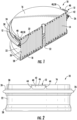
FIG. 1 is an isometric and cross-sectional view of a primary air filter element according to a first illustrated embodiment of the present invention; -
FIG. 2 is a side view of the air filter element ofFIG. 1 ; -
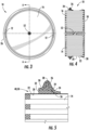
FIG. 3 is top view of the air filter element ofFIG. 1 ; -
FIG. 4 is a cross-sectional view of the air filter element ofFIG. 3 taken about line A-A; -
FIG. 5 is an enlarged view of a portion ofFIG. 4 ; -
FIG. 6 is an isometric and cross-sectional view of a secondary air filter element usable downstream in fluidic series of the primary air filter ofFIG. 1 , and according to a second illustrated embodiment of the present invention; -
FIG. 7 is a top view of the air filter shown inFIG. 6 ; -
FIG. 8 is a cross-sectional view of the air filter element ofFIG. 7 taken about line A-A; -
FIG. 9 is a side view of the air filter shown inFIG. 6 ; -
FIG. 10 is an enlarged view of a portion ofFIG. 8 ; -
FIG. 11 is an isometric view of a primary air filter element according to a third illustrated embodiment of the present invention; -
FIG. 12 is a cross sectional view of the air filter element shown inFIG. 11 ; - FIG. 13 is an enlarged isometric view of the bail handle connection illustrated in
FIG. 11 ; - FIG. 14 is an enlarged view of a portion of
FIG. 12 ; - FIG. 15 is an enlarged view of the handle structure in the form of handled mount of the embodiment of
FIG. 11 ; and - FIG. 16 is an enlarged view of the mounting end of the bail handle of the embodiment of
FIG. 11 . - While the invention will be described in connection with certain preferred embodiments, there is no intent to limit it to those embodiments. On the contrary, the intent is to cover all alternatives, modifications and equivalents as included within the spirit and scope of the invention as defined by the appended claims.
- Turning to
FIG. 1 , anair filter element 10 with an improved handle structure in the form of a pair ofhandles 12 is illustrated in accordance with a first embodiment of the present invention. Theair filter element 10 includes a mass of media such as afilter media pack 14 comprising a suitable air filter media (e.g. typically non-woven fibrous media of cellulose and/or synthetic polymeric fibers in a sheet). Thefilter media pack 14 defines aninlet face 16, anoutlet face 18 and anouter periphery 20 that is an annular side (e.g. cylindrical outer wall in the present embodiment). Theouter periphery 20 faces radially outward and extends axially between theinlet face 16 and theoutlet face 18 to provide a filtered fluid flow path extending axially from the inlet face to the outlet face and through the air filter media for contaminant removal. This may be considered to be an axial flow type filter (also referenced as an inline filter, in that the air can pass through the faces generally along the same direction). - The
filter media pack 14 in this embodiment is preferably a fluted filter media pack, which is known in the art to comprise a fluted sheet and a facing sheet that are secured together to define inlet flutes occluded a the outlet end and outlet flutes occluded at the inlet end so that unfiltered air must pass through one of the sheets of filter media to remove contaminants from the airflow. For example, a suitable fluted filter media pack and method of manufacture useable for the media pack herein is shown for example in the aforementionedU.S. Patent No. 8,083,825 to Mosset et al. and/orUS 7,255,300 to Johnston et al. entitled "Method and apparatus for winding a filter media pack," which is also incorporated by reference in its entirety. - Optionally but preferably, an
outer wrapper 22 such as provided inUS 2019/0105593 and entitled "Surface Coated Filter Method" may be utilized. For example,outer wrapper 22 may be an integrally formed outer layer such as by spray or roller coating of polyurea material, however adhesively attached preformed wrappers of plastic sheet and/or of porous material such as a spun-bounded sheet may be used. - The
air filter element 10 includes aframe 24 secured to thefilter media pack 14 and in surrounding relation of theouter periphery 20. For example, thefilter media pack 14 can be secured to theframe 24 through an annular adhesive of polyurethane that attaches theframe 14 through theouter wrapper 22. - The frame is preferably a rigid structure such as made from rigid plastic and preferably nylon reinforced with glass fibers.
- The
frame 24 can comprise anannular band 30 secured to theouter periphery 20 of the filter media pack via an adhesive 32. Theannular band 30 extends axially but in radially spaced relation to thefilter media pack 14 to define a potting well 34 therebetween, with the adhesive 32 being disposed in the potting well 34 for securement. Theframe 24 may also include anannular shutoff lip 36 closing the potting well 34 at bottom of theannular band 30 while leaving an adequate fillable entrance region at the top for receipt of the adhesive, which is preferably a curable resin such as urethane that can also seal between the annular band and the filter media pack. - Further, preferably, the
air filter element 10 includes a seal ring such as provided by agasket 26 that is arranged in surrounding relation of thefilter media pack 14. As illustrated, thegasket 26 may be supported by and mounted on theframe 24. - In this embodiment, the
gasket 26 is considered a "dust seal" in that it serves to prevent dust penetrating along the side during use to help for cleaner change-out and/or as a back-up for a primary seal provided byradial seal gasket 28 secured proximate theoutlet face 18. The dustseal type gasket 26 may be arranged proximate theinlet face 16 as illustrated. As shown, thegasket 26 is preferably an axial seal gasket but may alternatively be a radial seal likeradial seal gasket 28, or as is the case in the second embodiment ofFIGS. 6-10 . - Further, the
frame 24 can include aseal support flange 38 extending radially outwardly from theannular band 30. The gasket 26 (e.g. a dust seal) can be mounted around theseal support flange 38 to cover top bottom and outer sides thereof. As illustrated, thegasket 26 circumscribes a radially outward facing face of theannular band 30. - Secured to the
frame 24 is a handle structure such as provided by thehandles 12. Thehandles 12 can be secured to the frame integrally such as being unitarily molded therewith as single monolithic structure. - The
handles 12 can be grasped by the service mechanic to assist with installation and/or removal and are preferably sized large enough to receive two or more fingers of a mechanics hand therethrough, often typically with gloves upon the fingers. To provide such functionality, each of thehandles 12 includehandle aperture 42 having a horizontal length of between 5 and 20 centimeters and a vertical/axial width of between 2 and 10 centimeters to provide for manual grasping manipulation. To provide the aperture, the handles may be in the form of a closed loop strap withvertical legs 44 extending integral with theannular band 30 and a connectingbar 46 extending horizontally and connected tops of thevertical legs 44. The connectingbar 46 can provide for thehandle top 40 that can be arranged in a preferred location relative to the inlet face. - While providing functionality for handling, the
handles 12 can also be arranged to provide for space savings and yet apply the force directly proximate to the periphery where the frame is located for reliable manipulation. As shown, thehandles 12 are secured to theframe 24 proximate theouter periphery 20, with the handle structures extending to a region inside of an outer perimeter of thegasket 26, and the handles are primarily contained between theinlet face 16 and theoutlet face 18 in that a majority of the axial span of the handle is disposed between inlet and outlet faces 16, 18. Preferably, a top 40 of thehandles 12 are generally flush with the inlet face. In certain arrangements, thehandle top 40 can be positioned to provide stop structure to coact and/or abut with a corresponding air cleaner housing surface for proper positioning therein. Also, by having this arrangement, space savings can be realized, while providing a good and reliable handle structure for grasping. By "generally flush" or "generally flat" or similarly, it is meant that it may be flush/coplanar or within 2 centimeters of being flush/coplanar. - Space savings may also be realized by the perimeter occupied. The handle structures are interposed in an annular region 48 between the
gasket 26 and thefilter media pack 14 and extend axially along theouter periphery 20 generally parallel therewith (generally parallel being parallel or within 20 degrees of parallel), and with a radial air gap 50 providing a radial clearance region between thehandle 12 and thepack 14 to allow a user to easily maneuver ones hand into the handle. Also as noted, the handle structures are preferably flush with or recessed below theinlet flow face 16. Finally, the handle structures need not interact with thewinder core 52 used for winding a fluted typefilter media pack 14, and force can be more directly applied to the seal support frame at the periphery rather than at a center region. - Turning to a second illustrated embodiment
FIGS. 6-10 , a secondaryair filter element 60 is illustrated, which may be usable in fluidic series with the primaryair filter element 10 of the first embodiment. This secondair filter element 60 also may incorporate animproved handle 62. In this second embodiment, theair filter element 60 also comprises afilter media pack 64 comprising an air filter media and having aninlet face 66, anoutlet face 68 and anouter periphery 70. Similarly, theouter periphery 70 extends between theinlet face 66 and theoutlet face 68, to provide a filtered fluid flow path extending axially from the inlet face to the outlet face and through the air filter media for contaminant removal. However, in this embodiment, the air filter media preferably is in the form of apleated sheet 72 having folds with creased pleat tips at the inlet and outlet faces, but it is also an axial and inline direct flow filter arrangement like the first embodiment, just that the filter media sheet is configured and gathered differently. This type of filter pack is sometimes referred to as a pleated panel filter. - This
air filter element 60 includes aframe 74 secured to theouter periphery 70 of thefilter media pack 64 and in surrounding relation of theouter periphery 70. Also, agasket 76 is arranged in surrounding relation of thefilter media pack 64 and that is preferably a radial seal gasket having an outerradial seal surface 78 that is compressible radially for radially sealing with a housing. - The
handles 62 are secured to theframe 74 proximate theouter periphery 70, with the handle structures similarly extending to a region inside of an outer perimeter of thegasket 76. Here however, thehandles 62 structures lying substantially flat with theinlet face 66 across and over theinlet face 66. - The
handles 62 are pivotable structures secured integral with theframe 74, with the handles being sufficiently thin and flexible to provide anintegral hinge 86. Theframe 74 can comprise anannular band 80 sealingly secured to theouter periphery 70 of the of thefilter media pack 64 such as with an annular application of adhesive 82 therebetween. Theannular band 80 has an outerperipheral face 84 facing radially outward, with thegasket 76 circumscribing and mounted to the outerperipheral face 84. - To provide for convenient manufacture, on opposite sides the frame further includes handle mount blocks 88 along an inner periphery of the
annular band 80. Theblocks 88 may defineslits 90 that receivetabs 91 of thehandles 62 with an integral arrangement such as via bonding or welding (e.g. sonic application or heat staking) to secure the handles in place. Such slits and tabs may also take the form of cylindrical pins and receiving holes. Each handle 62 can comprise aresilient handle loop 94 to provide ahandle aperture 92. Theloops 94 extend from a mounting base 96 (that includes insertion tab 91), with the base preferably integrally formed such as being welded to one of the mounting blocks 88. Theloop 94 can provide a handle strap extending therefrom that lies substantially flat with theinlet face 66 when installed, thereby not occupying space, but is resilient pivotable from the mounting base via the flexibility allowed in the thinness of material at thehinges 86 to provide clearance to be grasped when pivoted. - Turning to a third embodiment of the present invention,
FIGS. 11 -16 illustrate a primaryair filter element 110 with an alternative handle arrangement to that of the first embodiment ofFIGS. 1-5 . However, this third embodiment is otherwise the same as the first embodiment such that the same reference numbers are used for the same structures, and it is understood that the description for the first embodiment is fully applicable to this embodiment other than as indicated. - The
air filter element 110 ofFIGS. 11 -16 also includes the same flutedfilter media pack 14 withinlet face 16,outlet face 18 andouter periphery 20, as well as the sameaxial seal gasket 26 andradial seal gasket 28. Optionalouter wrapper 22 may also be employed. - The
frame 124 is mostly the same in that it also includesannular band 130 adhesively mounted in the same way such as via a urethane pour, however, the handle structures in this embodiment are in the form of handle mounts provided by vertically and axially projectingears 112 that project from theannular band 130. Theears 112 pivotably support abail handle 146 that is pivotably mounted to thepair support ears 112. - The bail handle 146 is pivotable between an extended position providing a loop over the
inlet face 16 for manual manipulation and a retracted position in which the bail handle is generally flush or below theinlet face 16, with the retracted position show inFIGS. 11 and 12 . Anannular clearance region 148 is defined radially between theframe 124 and thefilter media pack 14. As shown best inFIGS. 11 and 12 , the bail handle in the retracted position occupies theannular clearance region 148, and in particular the bail handle can be retracted to one side or the other side of thesupport ears 112 due to symmetry. - To provide for a pivotable connection, a
hinge structure 154 is provided and may be formed between ends of thebail handle 146 and thesupport ears 112. For example, each of theears 112 may have apertures 142 (which may include an insert slot 156 and a pivot aperture 158, with a snap project rib 157 therebetween), while thebail handle 146 may have pivot projections 159 including a neck portion 160 and a retainer head portion 162. For assembly, the pivot projections 159 can be assembled due to the resiliently flexible nature of thebail handle 146 due to its length and thinness (which also may be a molded plastic member), with the head portions 162 insertable into the enlarged insert slot 156 and with the neck portions 160 then snapped and slid past the snap rib 157 to position the neck regions in the pivot aperture 158 and retained therein due to the enlarged head portion 162 being larger than the pivot aperture 142). As such thebail handle 146 comprises a pair of projections snap fit into respective apertures of the support ears. - Further embodiments or aspects of the present disclosure are described in the following numbered clauses:
- 1. An air filter element, comprising: a filter media pack comprising an air filter media and having an inlet face, an outlet face and an outer periphery, the outer periphery extending between the inlet face and the outlet face, a filtered fluid flow path extending axially from the inlet face to the outlet face and through the air filter media for contaminant removal; a frame secured to the filter media pack and in surrounding relation of the outer periphery; a gasket arranged in surrounding relation of the filter media pack; a plurality of handle structures secured to the frame proximate the outer periphery, the handle structures extending to a region inside of an outer perimeter of the gasket, and the handle structures being at least one of: (a) primarily contained between the inlet face and the outlet face and (b) lying substantially flat with the inlet face.
- 2. The air filter element of
clause 1, wherein the handle structures are primarily contained between the inlet face and the outlet face. - 3. The air filter element of clause 2, wherein a top of the handle structures are generally flush with the inlet face.
- 4. The air filter element of
clause 1, wherein the handle structures are lying substantially flat with the inlet face and extend across the inlet face, wherein the handle structures comprise pivotable handles secured integral with the frame, the handles being sufficiently thin and flexible to provide an integral hinge. - 5. The air filter element of
clause 1, wherein the handle structures are interposed in an annular region between the gasket and the filter media pack and extend axially along the outer periphery generally parallel therewith and in spaced relation to the filter media pack with an air gap therebetween, with generally parallel being parallel or within 20 degrees of parallel. - 6. The air filter element of
clause 1, wherein a portion of the handle structure is generally flush with the inlet face, generally flush being flush or within 2 centimeters of being flush. - 7. The air filter element of clause 6, wherein the top of the handle structure provides mechanical stop means for proper installing and positioning of the air filter element.
- 8. The air filter element of
clause 1, wherein each of the handle structures is a handle defining an aperture having a length of between 5 and 20 centimeters and a width of between 2 and 10 centimeters to provide for manual grasping manipulation. - 9. The air filter element of
clause 1, wherein the handle structures comprises a pair of handle mounts including support ears extending from an annular band of the frame, and further a bail handle pivotably mounted to the pair support ears. - 10. The air filter element of clause 9, wherein the bail handle is pivotable between an extended position providing a loop over the inlet face for manual manipulation and a retracted position in which the bail handle is generally flush or below the inlet face.
- 11. The air filter element of
clause 10, wherein an annular clearance region is defined radially between the frame and the filter media pack, wherein the bail handle in the retracted position occupies the annular clearance region, and wherein the bail handle comprises a pair of projections snap fit into respective apertures of the support ears. - 12. The air filter element of
clause 1, wherein the handle structures are flush or recessed below the inlet face. - 13. The air filter element of
clause 1, wherein the frame comprises an annular band secured to the outer periphery of the filter media pack via an adhesive, the annular band extending axially in spaced relation to the filter media pack defining a potting well therebetween, the adhesive being disposed in the potting well, the frame including an annular shutoff lip closing the potting well at bottom of the annular band. - 14. The air filter element of clause 13, wherein the adhesive comprises urethane material.
- 15. The air filter element of clause 13, wherein the handle structures are unitary with the annular band.
- 16. The air filter element of clause 13, wherein the frame includes a seal support flange extending radially from the annular band, the gasket being a dust seal mounted around the seal support flange to cover top bottom and outer sides.
- 17. The air filter element of
clause 1, wherein the frame comprises an annular band secured to the outer periphery of the filter media pack, and the annular band having an outer peripheral face facing radially outward, the gasket circumscribing and mounted to the outer peripheral face, and wherein the filter media pack comprises a pleated filter panel. - 18. The air filter element of clause 17, wherein on opposite sides the frame further includes handle mount blocks along an inner periphery of the annular band, and wherein each handle structure comprises a resilient handle including a mounting base integrally formed and welded to one of the mounting blocks and a handle strap extending therefrom that lies substantially flat with the inlet face and is resilient pivotable from the mounting base to be grasped.
- 19. The air filter element of
clause 1, wherein the frame comprises an annular band secured to the outer periphery of the filter media pack via an adhesive, the annular band extending axially with the handle structures extending axially therefrom and in spaced relation to the filter media pack to define a radial clearance region configured for handle manipulation, wherein the gasket circumscribes a radially outward facing face of the annular band. - 20. The air filter element of
clause 1, wherein the filter media comprises a gathered sheet of fibrous filter media, the gathered sheet comprising being at least one of a pleated panel filter configuration and a fluted filter pack configuration wherein fluted media is secured to facing media. - 21. A filter element including i) a mass of media having an inlet face at one end and an outlet face at another end, and ii) a rigid frame fixed to and circumferentially surrounding the media around the outer periphery thereof, the frame including an annular body portion and a pair of handles formed integrally with the body portion and projecting freely from the body portion toward or across one of the ends of the element, wherein the handles are located and sized for grasping by a user to remove the element from a housing.
- 22. The filter element as in clause 21, wherein the handles are unitary with the body portion.
- 23. The filter element as in clause 21, further including a gasket supported by the frame and circumferentially surrounding the element.
- 24. The filter element of clause 21, wherein the body portion comprises an annular band secured to the outer periphery of the filter media pack via an adhesive, the annular band extending axially in spaced relation to the filter media pack defining a potting well therebetween, the adhesive being disposed in the potting well, the frame including an annular shutoff lip closing the potting well at bottom of the annular band, the body portion also including a seal support flange supporting an annular gasket, the handles extending to a region inside of an outer perimeter of the gasket.
- 25. The filter element of clause 21, wherein the annular body portion comprises an annular band secured to the outer periphery of the filter media pack, and the annular band having an outer peripheral face facing radially outward, the gasket circumscribing and mounted to the outer peripheral face, and wherein the filter media pack comprises a pleated filter panel.
- 26. The filter element of clause 25, wherein on opposite sides the frame further includes handle mount blocks along an inner periphery of the annular band, and wherein each handle structure comprises a resilient handle including a mounting base integrally formed by being welded to one of the mounting blocks and a handle strap extending therefrom that lies substantially flat with the inlet face and is resilient pivotable from the mounting base be grasped.
- 27. A filter element including i) a mass of media having an inlet face at one end and an outlet face at another end and surrounding a central core, and ii) a dust seal assembly circumferentially surrounding the element along an outer surface thereof, the dust seal assembly including a rigid frame fixed to the surface, and at least one handle structure formed integrally with an annular body portion of the frame and projecting freely from the body portion toward one of the ends of the element.
- 28. The filter element of clause 27, wherein the at least one handle structure comprises a pair of handles are located and sized for grasping by a user to remove the element from a housing.
- 29. The filter element of clause 27, wherein a top of the at least one handle structure is generally flush with the inlet face.
- 30. The filter element of clause 27, wherein the at least one handle structure comprises a pair of handle mounts including support ears extending from an annular band of the frame, and further a bail handle pivotably mounted to the pair support ears.
- 31. The filter element of
clause 30, wherein the bail handle is pivotable between an extended position providing a loop over the inlet face for manual manipulation and a retracted position in which the bail handle is generally flush or below the inlet face. - 32. The filter element of
clause 28, wherein the frame comprises an annular band secured to the outer periphery of the filter media pack via an adhesive, the annular band extending axially in spaced relation to the filter media pack defining a potting well therebetween, the adhesive being disposed in the potting well, the frame including an annular shutoff lip closing the potting well at bottom of the annular band. - 33. The filter element of
clause 32, wherein the adhesive comprises urethane material. - 34. The filter element of clause 27, wherein the at least one handle structure comprises a pair of handle structures unitary with the annular band.
- 35. The filter element of clause 27, wherein the frame includes a seal support flange extending radially from the annular band, the gasket being a dust seal mounted around the seal support flange to cover top bottom and outer sides.
- 36. A filter element including i) a mass of media having an inlet face at one end and an outlet face at another end, and ii) a gasket assembly circumferentially surrounding the element along an outer surface thereof, the gasket assembly including a rigid frame fixed to and supporting the element, and at least one handle integral with an annular body portion of the frame and projecting freely from the body portion across one of the ends of the element, where the at least one handle is located and sized for grasping by a user to remove the element from a housing.
- 37. The filter element of
clause 36, wherein the rigid frame comprises an annular band secured to the outer periphery of the filter media pack, and the annular band having an outer peripheral face facing radially outward, the gasket circumscribing and mounted to the outer peripheral face, and wherein the mass of media comprises a pleated filter panel. - 38. The filter element of clause 37, wherein on opposite sides the rigid frame further includes at least one handle mount block along an inner periphery of the annular band, and wherein each handle comprises a resilient handle including a mounting base integrally integral to one of the at least one mounting block and a handle strap extending therefrom that lies substantially flat with the inlet face and is resilient pivotable from the mounting base be grasped.
- 39. The filter element of
clause 36, wherein the at least one handle is lying substantially flat with the inlet face and extend across the inlet face, wherein the at least one handle comprises a pivotable handle secured integral with the frame, the pivotable handle being sufficiently thin and flexible to provide an integral hinge. - 40. The filter element of
clause 36, wherein the at least one handle comprises a pair of handles on opposite sides of the frame. - All references, including publications, patent applications, and patents cited herein are hereby incorporated by reference to the same extent as if each reference were individually and specifically indicated to be incorporated by reference and were set forth in its entirety herein.
- The use of the terms "a" and "an" and "the" and similar referents in the context of describing the invention (especially in the context of the following claims) is to be construed to cover both the singular and the plural, unless otherwise indicated herein or clearly contradicted by context. The terms "comprising," "having," "including," and "containing" are to be construed as open-ended terms (i.e., meaning "including, but not limited to,") unless otherwise noted. Recitation of ranges of values herein are merely intended to serve as a shorthand method of referring individually to each separate value falling within the range, unless otherwise indicated herein, and each separate value is incorporated into the specification as if it were individually recited herein. All methods described herein can be performed in any suitable order unless otherwise indicated herein or otherwise clearly contradicted by context. The use of any and all examples, or exemplary language (e.g., "such as") provided herein, is intended merely to better illuminate the invention and does not pose a limitation on the scope of the invention unless otherwise claimed. No language in the specification should be construed as indicating any non-claimed element as essential to the practice of the invention.
- Preferred embodiments of this invention are described herein, including the best mode known to the inventors for carrying out the invention. Variations of those preferred embodiments may become apparent to those of ordinary skill in the art upon reading the foregoing description. The inventors expect skilled artisans to employ such variations as appropriate, and the inventors intend for the invention to be practiced otherwise than as specifically described herein. Accordingly, this invention includes all modifications and equivalents of the subject matter recited in the claims appended hereto as permitted by applicable law. Moreover, any combination of the above-described elements in all possible variations thereof is encompassed by the invention unless otherwise indicated herein or otherwise clearly contradicted by context.
Claims (9)
- A filter element including i) a mass of media having an inlet face at one end and an outlet face at another end, and ii) a gasket assembly circumferentially surrounding the mass of media of the filter element along an outer surface thereof, the gasket assembly including a rigid frame fixed to and supporting the mass of media of the filter element, and at least one handle integral with an annular body portion of the frame and projecting freely from the body portion across one of the ends of the mass of media of the filter element, where the at least one handle is located and sized for grasping by a user to remove the filter element from a housing.
- The filter element of claim 1, wherein the rigid frame comprises an annular band secured to the outer periphery of the mass of media of the filter element, and the annular band having an outer peripheral face facing radially outward, the gasket circumscribing and mounted to the outer peripheral face, and wherein the mass of media comprises a pleated filter panel.
- The filter element of claim 2, wherein on opposite sides the rigid frame further includes at least one handle mount block along an inner periphery of the annular band, and wherein each handle comprises a resilient handle including a mounting base integrally integral to one of the at least one mounting block and a handle strap extending therefrom that lies substantially flat with the inlet face and is resilient pivotable from the mounting base be grasped.
- The filter element of claim 1, wherein the at least one handle is lying substantially flat with the inlet face and extend across the inlet face, wherein the at least one handle comprises a pivotable handle secured integral with the frame, the pivotable handle being sufficiently thin and flexible to provide an integral hinge.
- The filter element of claim 1, wherein the at least one handle comprises a pair of handles on opposite sides of the frame.
- An air filter element, comprising:a filter media pack comprising an air filter media and having an inlet face, an outlet face and an outer periphery, the outer periphery extending between the inlet face and the outlet face, a filtered fluid flow path extending axially from the inlet face to the outlet face and through the air filter media for contaminant removal;a frame secured to the filter media pack and in surrounding relation of the outer periphery;a gasket arranged in surrounding relation of the filter media pack;a plurality of handle structures secured to the frame proximate the outer periphery, the handle structures extending to a region inside of an outer perimeter of the gasket, and the handle structures lying substantially flat with the inlet face.
- The air filter element of claim 6, wherein the handle structures are lying substantially flat with the inlet face and extend across the inlet face, wherein the handle structures comprise pivotable handles secured integral with the frame, the handles being sufficiently thin and flexible to provide an integral hinge.
- The air filter element of claim 6, wherein the frame comprises an annular band secured to the outer periphery of the filter media pack, and the annular band having an outer peripheral face facing radially outward, the gasket circumscribing and mounted to the outer peripheral face, and wherein the filter media pack comprises a pleated filter panel.
- The air filter element of claim 8, wherein on opposite sides the frame further includes handle mount blocks along an inner periphery of the annular band, and wherein each handle structure comprises a resilient handle including a mounting base integrally formed and welded to one of the mounting blocks and a handle strap extending therefrom that lies substantially flat with the inlet face and is resilient pivotable from the mounting base to be grasped.
Applications Claiming Priority (4)
| Application Number | Priority Date | Filing Date | Title |
|---|---|---|---|
| US201962815387P | 2019-03-08 | 2019-03-08 | |
| US201962851357P | 2019-05-22 | 2019-05-22 | |
| PCT/US2020/021161 WO2020185505A1 (en) | 2019-03-08 | 2020-03-05 | Air filter with improved handle |
| EP20770189.7A EP3934789B1 (en) | 2019-03-08 | 2020-03-05 | Air filter with improved handle |
Related Parent Applications (2)
| Application Number | Title | Priority Date | Filing Date |
|---|---|---|---|
| EP20770189.7A Division EP3934789B1 (en) | 2019-03-08 | 2020-03-05 | Air filter with improved handle |
| EP20770189.7A Division-Into EP3934789B1 (en) | 2019-03-08 | 2020-03-05 | Air filter with improved handle |
Publications (3)
| Publication Number | Publication Date |
|---|---|
| EP4316627A2 true EP4316627A2 (en) | 2024-02-07 |
| EP4316627A3 EP4316627A3 (en) | 2024-02-28 |
| EP4316627B1 EP4316627B1 (en) | 2025-05-07 |
Family
ID=72426453
Family Applications (2)
| Application Number | Title | Priority Date | Filing Date |
|---|---|---|---|
| EP23218333.5A Active EP4316627B1 (en) | 2019-03-08 | 2020-03-05 | Air filter with improved handle |
| EP20770189.7A Active EP3934789B1 (en) | 2019-03-08 | 2020-03-05 | Air filter with improved handle |
Family Applications After (1)
| Application Number | Title | Priority Date | Filing Date |
|---|---|---|---|
| EP20770189.7A Active EP3934789B1 (en) | 2019-03-08 | 2020-03-05 | Air filter with improved handle |
Country Status (4)
| Country | Link |
|---|---|
| US (1) | US12303817B2 (en) |
| EP (2) | EP4316627B1 (en) |
| BR (1) | BR112021016941A2 (en) |
| WO (1) | WO2020185505A1 (en) |
Families Citing this family (2)
| Publication number | Priority date | Publication date | Assignee | Title |
|---|---|---|---|---|
| US20260007992A1 (en) * | 2024-07-02 | 2026-01-08 | Camfil Usa, Inc. | Air filter |
| WO2026142827A1 (en) | 2024-12-23 | 2026-07-02 | Baldwin Filters, Inc. | Multi-functional inlet frame for air filter |
Citations (9)
| Publication number | Priority date | Publication date | Assignee | Title |
|---|---|---|---|---|
| US1002587A (en) | 1911-04-14 | 1911-09-05 | Karl Kiefer | Filter element. |
| US2731155A (en) | 1953-03-27 | 1956-01-17 | Fram Corp | Filter cartridge pull-out device |
| US2739667A (en) | 1954-08-02 | 1956-03-27 | American Air Filter Co | Filter frame |
| GB2299769A (en) | 1995-04-11 | 1996-10-16 | Philips Electronics Uk Ltd | Air cleaner with slidably removable filter elements |
| US6610126B2 (en) | 2001-06-06 | 2003-08-26 | Donaldson Company, Inc. | Filter element having sealing members and methods |
| US6852141B2 (en) | 2001-06-06 | 2005-02-08 | Donaldson Company, Inc. | Filter element having center piece and methods |
| US7255300B2 (en) | 2004-11-03 | 2007-08-14 | Baldwin Filters, Inc. | Method and apparatus for winding a filter media pack |
| US8083825B2 (en) | 2005-02-28 | 2011-12-27 | Donaldson Company, Inc. | Filter arrangement and method |
| US20190105593A1 (en) | 2016-02-19 | 2019-04-11 | Baldwin Filters, Inc. | Surface coated filter method |
Family Cites Families (34)
| Publication number | Priority date | Publication date | Assignee | Title |
|---|---|---|---|---|
| US2771154A (en) * | 1952-09-12 | 1956-11-20 | American Air Filter Co | Filter frame handle construction |
| US5556440A (en) * | 1994-10-20 | 1996-09-17 | Fleetguard, Inc. | Pressure-actuated radial air filter seal |
| US6235195B1 (en) | 1999-02-26 | 2001-05-22 | Donaldson Company, Inc. | Filter element incorporating a handle member |
| US6517598B2 (en) | 2001-06-06 | 2003-02-11 | Donaldson Company, Inc. | Filter element having flange and methods |
| US6966940B2 (en) | 2002-04-04 | 2005-11-22 | Donaldson Company, Inc. | Air filter cartridge |
| KR100956706B1 (en) | 2002-05-09 | 2010-05-06 | 도날드슨 컴파니, 인코포레이티드 | Air filter with pull root filter media |
| US7168573B2 (en) | 2002-06-07 | 2007-01-30 | Baldwin Filters, Inc. | Environmentally friendly filter cartridge |
| CA2516007C (en) | 2003-02-11 | 2014-09-02 | Donaldson Company, Inc. | Air cleaner arrangements; serviceable filter elements; and, methods |
| CN1890013B (en) * | 2003-11-12 | 2010-10-27 | 唐纳森公司 | Air filter with a sliding frame for a filter element |
| EP2679293A1 (en) | 2004-03-24 | 2014-01-01 | Donaldson Company, Inc. | Air Cleaner |
| US7905936B2 (en) | 2004-04-30 | 2011-03-15 | Donaldson Company, Inc. | Filter arrangements; housing; assemblies; and, methods |
| US8048188B2 (en) | 2004-06-18 | 2011-11-01 | Donaldson Company, Inc. | Air cleaner arrangements; serviceable filter cartridge; and, methods |
| DE602005019417D1 (en) | 2004-07-20 | 2010-04-01 | Donaldson Co Inc | Z-FILTERMEDIENPACKUNGSANORDNUNG, FILTERPATRONE, AIR CLEANING DEVICE ARRANGEMENT AND METHOD |
| WO2006014941A2 (en) | 2004-07-26 | 2006-02-09 | Donaldson Company, Inc. | Z-filter media pack arrangement; and, methods |
| US7326342B2 (en) | 2004-09-13 | 2008-02-05 | Baldwin Filters, Inc. | Fuel filter cartridge and keyed end cap |
| US7318851B2 (en) | 2004-11-02 | 2008-01-15 | Baldwin Filters, Inc. | Filter element |
| US7261756B2 (en) | 2004-11-02 | 2007-08-28 | Baldwin Filters, Inc. | Safety filter element |
| US7931725B2 (en) | 2004-11-02 | 2011-04-26 | Baldwin Filters, Inc. | Fluted filter apparatus |
| DE102005031058A1 (en) * | 2005-07-02 | 2007-01-04 | Mahle International Gmbh | Filter element and a filter housing suitable for receiving it |
| EP1986761A2 (en) | 2006-01-20 | 2008-11-05 | Donaldson Company, Inc. | Air cleaner configured for receipt of various sized filter cartridges; components thereof; and, methods |
| US7625419B2 (en) | 2006-05-10 | 2009-12-01 | Donaldson Company, Inc. | Air filter arrangement; assembly; and, methods |
| GB2440515B (en) | 2006-08-01 | 2011-06-15 | Dyson Technology Ltd | A filter assembly |
| US8709248B2 (en) | 2007-07-11 | 2014-04-29 | Baldwin Filters, Inc. | Molded filter end cap and method of manufacture |
| SE0701933L (en) * | 2007-08-27 | 2008-12-16 | Electrolux Ab | Detachable filter insert for a vacuum cleaner |
| US8728193B2 (en) * | 2007-09-07 | 2014-05-20 | Donaldson Company, Inc. | Air filter assembly; components thereof and methods |
| US9675225B2 (en) | 2008-07-04 | 2017-06-13 | Emerson Electric Co. | Filter cage for wet/dry vacuums |
| WO2010114906A1 (en) | 2009-03-31 | 2010-10-07 | Donaldson Company, Inc. | Air cleaner, components thereof, and methods |
| CN102264452B (en) | 2009-10-02 | 2016-02-24 | 唐纳森公司 | There is the filter element of central plate, dust arrester and method |
| DE112014003011T5 (en) | 2013-06-28 | 2016-03-10 | Donaldson Company, Inc. | Filter cartridges, air cleaner assemblies, housings, features, components and methods |
| JP6352076B2 (en) * | 2013-07-12 | 2018-07-04 | マン ウント フンメル ゲゼルシャフト ミット ベシュレンクテル ハフツング | Filter element having handgrip element and filter having filter element |
| US10974188B2 (en) | 2015-07-15 | 2021-04-13 | Baldwin Filters, Inc. | Filter with shield features |
| DE102016001132A1 (en) | 2016-02-03 | 2017-08-03 | Mann + Hummel Gmbh | Filter element, element frame of a filter element, filter bellows of a filter element, filter housing and filter |
| DE102016001134A1 (en) * | 2016-02-03 | 2017-08-03 | Mann + Hummel Gmbh | Filter housing and filter |
| CN109715265B (en) * | 2016-07-06 | 2021-11-19 | 唐纳森公司 | Air filter assembly |
-
2020
- 2020-03-05 EP EP23218333.5A patent/EP4316627B1/en active Active
- 2020-03-05 BR BR112021016941A patent/BR112021016941A2/en active IP Right Grant
- 2020-03-05 EP EP20770189.7A patent/EP3934789B1/en active Active
- 2020-03-05 WO PCT/US2020/021161 patent/WO2020185505A1/en not_active Ceased
-
2021
- 2021-06-17 US US17/350,429 patent/US12303817B2/en active Active
Patent Citations (17)
| Publication number | Priority date | Publication date | Assignee | Title |
|---|---|---|---|---|
| US1002587A (en) | 1911-04-14 | 1911-09-05 | Karl Kiefer | Filter element. |
| US2731155A (en) | 1953-03-27 | 1956-01-17 | Fram Corp | Filter cartridge pull-out device |
| US2739667A (en) | 1954-08-02 | 1956-03-27 | American Air Filter Co | Filter frame |
| GB2299769A (en) | 1995-04-11 | 1996-10-16 | Philips Electronics Uk Ltd | Air cleaner with slidably removable filter elements |
| US6878190B1 (en) | 2001-06-06 | 2005-04-12 | Donaldson Company, Inc. | Filter element having sealing members and methods |
| US6852141B2 (en) | 2001-06-06 | 2005-02-08 | Donaldson Company, Inc. | Filter element having center piece and methods |
| US8608818B2 (en) | 2001-06-06 | 2013-12-17 | Donaldson Company, Inc. | Filter element having sealing members and methods |
| US6997968B2 (en) | 2001-06-06 | 2006-02-14 | Donaldson Company, Inc. | Filter element having sealing members and methods |
| US6610126B2 (en) | 2001-06-06 | 2003-08-26 | Donaldson Company, Inc. | Filter element having sealing members and methods |
| US7393375B2 (en) | 2001-06-06 | 2008-07-01 | Donaldson Company, Inc. | Filter element having sealing members and methods |
| US7691166B2 (en) | 2001-06-06 | 2010-04-06 | Donaldson Company, Inc. | Filter element having sealing members and methods |
| US7976601B2 (en) | 2001-06-06 | 2011-07-12 | Donaldson Company, Inc. | Filter element having sealing members and methods |
| US20140338294A1 (en) | 2001-06-06 | 2014-11-20 | Donaldson Company, Inc. | Filter element having sealing members and methods |
| US8246707B2 (en) | 2001-06-06 | 2012-08-21 | Donaldson Company, Inc. | Filter element having sealing members and methods |
| US7255300B2 (en) | 2004-11-03 | 2007-08-14 | Baldwin Filters, Inc. | Method and apparatus for winding a filter media pack |
| US8083825B2 (en) | 2005-02-28 | 2011-12-27 | Donaldson Company, Inc. | Filter arrangement and method |
| US20190105593A1 (en) | 2016-02-19 | 2019-04-11 | Baldwin Filters, Inc. | Surface coated filter method |
Also Published As
| Publication number | Publication date |
|---|---|
| EP3934789A1 (en) | 2022-01-12 |
| EP4316627B1 (en) | 2025-05-07 |
| EP3934789B1 (en) | 2024-01-24 |
| US20210308613A1 (en) | 2021-10-07 |
| US12303817B2 (en) | 2025-05-20 |
| EP4316627A3 (en) | 2024-02-28 |
| EP3934789A4 (en) | 2022-10-26 |
| BR112021016941A2 (en) | 2021-11-03 |
| WO2020185505A1 (en) | 2020-09-17 |
Similar Documents
| Publication | Publication Date | Title |
|---|---|---|
| US8673043B2 (en) | Fluid filter | |
| EP2227306B1 (en) | Filter assembly | |
| CA2585961C (en) | Filter element with canted seal support | |
| CN103987437B (en) | cartridge filter system | |
| US20060091064A1 (en) | Filter apparatus with separable seal support frame | |
| EP3013455B1 (en) | Air filter and inlet tube assembly | |
| EP4252887B1 (en) | Filter system and filter element | |
| US20150316009A1 (en) | Filter Element | |
| KR20150091356A (en) | Filter cartridges, features and methods of assembly, filter assemblies, and filter cartridge combinations | |
| AU2005301228B2 (en) | Safety filter element | |
| AU2005301259A2 (en) | Filter assembly with sealing system | |
| CN114151246A (en) | Air filter assembly | |
| US12303817B2 (en) | Air filter with improved handle | |
| EP3559436B1 (en) | Filter with preformed end caps having notch feature | |
| WO2006049758A1 (en) | Filter assembly with combination filter element | |
| US20170291132A1 (en) | Axial flow air filter element | |
| CN109289335B (en) | Filter element and filter system having a filter element | |
| EP4326420B1 (en) | Filter cartridge including u-shaped canted inlet frame; filter system including same | |
| JP4831355B2 (en) | Air cleaner | |
| US20130008844A1 (en) | Fluid Filter | |
| JP2025513434A (en) | Filter Elements and Assemblies | |
| EP4221865B1 (en) | Filter element | |
| BR122025001878A2 (en) | FILTER ELEMENT |
Legal Events
| Date | Code | Title | Description |
|---|---|---|---|
| PUAI | Public reference made under article 153(3) epc to a published international application that has entered the european phase |
Free format text: ORIGINAL CODE: 0009012 |
|
| STAA | Information on the status of an ep patent application or granted ep patent |
Free format text: STATUS: THE APPLICATION HAS BEEN PUBLISHED |
|
| REG | Reference to a national code |
Ref country code: DE Ref legal event code: R079 Free format text: PREVIOUS MAIN CLASS: B01D0046000000 Ipc: B01D0046520000 Ref document number: 602020051140 Country of ref document: DE |
|
| PUAL | Search report despatched |
Free format text: ORIGINAL CODE: 0009013 |
|
| AC | Divisional application: reference to earlier application |
Ref document number: 3934789 Country of ref document: EP Kind code of ref document: P |
|
| AK | Designated contracting states |
Kind code of ref document: A2 Designated state(s): AL AT BE BG CH CY CZ DE DK EE ES FI FR GB GR HR HU IE IS IT LI LT LU LV MC MK MT NL NO PL PT RO RS SE SI SK SM TR |
|
| AK | Designated contracting states |
Kind code of ref document: A3 Designated state(s): AL AT BE BG CH CY CZ DE DK EE ES FI FR GB GR HR HU IE IS IT LI LT LU LV MC MK MT NL NO PL PT RO RS SE SI SK SM TR |
|
| RIC1 | Information provided on ipc code assigned before grant |
Ipc: B01D 46/00 20220101ALI20240124BHEP Ipc: B01D 46/52 20060101AFI20240124BHEP |
|
| P01 | Opt-out of the competence of the unified patent court (upc) registered |
Effective date: 20240408 |
|
| STAA | Information on the status of an ep patent application or granted ep patent |
Free format text: STATUS: REQUEST FOR EXAMINATION WAS MADE |
|
| 17P | Request for examination filed |
Effective date: 20240807 |
|
| RBV | Designated contracting states (corrected) |
Designated state(s): AL AT BE BG CH CY CZ DE DK EE ES FI FR GB GR HR HU IE IS IT LI LT LU LV MC MK MT NL NO PL PT RO RS SE SI SK SM TR |
|
| GRAP | Despatch of communication of intention to grant a patent |
Free format text: ORIGINAL CODE: EPIDOSNIGR1 |
|
| STAA | Information on the status of an ep patent application or granted ep patent |
Free format text: STATUS: GRANT OF PATENT IS INTENDED |
|
| INTG | Intention to grant announced |
Effective date: 20241114 |
|
| GRAJ | Information related to disapproval of communication of intention to grant by the applicant or resumption of examination proceedings by the epo deleted |
Free format text: ORIGINAL CODE: EPIDOSDIGR1 |
|
| STAA | Information on the status of an ep patent application or granted ep patent |
Free format text: STATUS: REQUEST FOR EXAMINATION WAS MADE |
|
| GRAP | Despatch of communication of intention to grant a patent |
Free format text: ORIGINAL CODE: EPIDOSNIGR1 |
|
| STAA | Information on the status of an ep patent application or granted ep patent |
Free format text: STATUS: GRANT OF PATENT IS INTENDED |
|
| INTC | Intention to grant announced (deleted) | ||
| INTG | Intention to grant announced |
Effective date: 20250127 |
|
| GRAS | Grant fee paid |
Free format text: ORIGINAL CODE: EPIDOSNIGR3 |
|
| GRAA | (expected) grant |
Free format text: ORIGINAL CODE: 0009210 |
|
| STAA | Information on the status of an ep patent application or granted ep patent |
Free format text: STATUS: THE PATENT HAS BEEN GRANTED |
|
| AC | Divisional application: reference to earlier application |
Ref document number: 3934789 Country of ref document: EP Kind code of ref document: P |
|
| AK | Designated contracting states |
Kind code of ref document: B1 Designated state(s): AL AT BE BG CH CY CZ DE DK EE ES FI FR GB GR HR HU IE IS IT LI LT LU LV MC MK MT NL NO PL PT RO RS SE SI SK SM TR |
|
| REG | Reference to a national code |
Ref country code: GB Ref legal event code: FG4D |
|
| REG | Reference to a national code |
Ref country code: CH Ref legal event code: EP |
|
| REG | Reference to a national code |
Ref country code: DE Ref legal event code: R096 Ref document number: 602020051140 Country of ref document: DE |
|
| REG | Reference to a national code |
Ref country code: IE Ref legal event code: FG4D |
|
| REG | Reference to a national code |
Ref country code: NL Ref legal event code: MP Effective date: 20250507 |
|
| PG25 | Lapsed in a contracting state [announced via postgrant information from national office to epo] |
Ref country code: PT Free format text: LAPSE BECAUSE OF FAILURE TO SUBMIT A TRANSLATION OF THE DESCRIPTION OR TO PAY THE FEE WITHIN THE PRESCRIBED TIME-LIMIT Effective date: 20250908 Ref country code: ES Free format text: LAPSE BECAUSE OF FAILURE TO SUBMIT A TRANSLATION OF THE DESCRIPTION OR TO PAY THE FEE WITHIN THE PRESCRIBED TIME-LIMIT Effective date: 20250507 Ref country code: FI Free format text: LAPSE BECAUSE OF FAILURE TO SUBMIT A TRANSLATION OF THE DESCRIPTION OR TO PAY THE FEE WITHIN THE PRESCRIBED TIME-LIMIT Effective date: 20250507 |
|
| REG | Reference to a national code |
Ref country code: LT Ref legal event code: MG9D |
|
| PG25 | Lapsed in a contracting state [announced via postgrant information from national office to epo] |
Ref country code: NO Free format text: LAPSE BECAUSE OF FAILURE TO SUBMIT A TRANSLATION OF THE DESCRIPTION OR TO PAY THE FEE WITHIN THE PRESCRIBED TIME-LIMIT Effective date: 20250807 Ref country code: GR Free format text: LAPSE BECAUSE OF FAILURE TO SUBMIT A TRANSLATION OF THE DESCRIPTION OR TO PAY THE FEE WITHIN THE PRESCRIBED TIME-LIMIT Effective date: 20250808 |
|
| PG25 | Lapsed in a contracting state [announced via postgrant information from national office to epo] |
Ref country code: NL Free format text: LAPSE BECAUSE OF FAILURE TO SUBMIT A TRANSLATION OF THE DESCRIPTION OR TO PAY THE FEE WITHIN THE PRESCRIBED TIME-LIMIT Effective date: 20250507 Ref country code: PL Free format text: LAPSE BECAUSE OF FAILURE TO SUBMIT A TRANSLATION OF THE DESCRIPTION OR TO PAY THE FEE WITHIN THE PRESCRIBED TIME-LIMIT Effective date: 20250507 |
|
| REG | Reference to a national code |
Ref country code: AT Ref legal event code: MK05 Ref document number: 1791886 Country of ref document: AT Kind code of ref document: T Effective date: 20250507 |
|
| PG25 | Lapsed in a contracting state [announced via postgrant information from national office to epo] |
Ref country code: BG Free format text: LAPSE BECAUSE OF FAILURE TO SUBMIT A TRANSLATION OF THE DESCRIPTION OR TO PAY THE FEE WITHIN THE PRESCRIBED TIME-LIMIT Effective date: 20250507 |
|
| PG25 | Lapsed in a contracting state [announced via postgrant information from national office to epo] |
Ref country code: HR Free format text: LAPSE BECAUSE OF FAILURE TO SUBMIT A TRANSLATION OF THE DESCRIPTION OR TO PAY THE FEE WITHIN THE PRESCRIBED TIME-LIMIT Effective date: 20250507 |
|
| PG25 | Lapsed in a contracting state [announced via postgrant information from national office to epo] |
Ref country code: AT Free format text: LAPSE BECAUSE OF FAILURE TO SUBMIT A TRANSLATION OF THE DESCRIPTION OR TO PAY THE FEE WITHIN THE PRESCRIBED TIME-LIMIT Effective date: 20250507 |
|
| PG25 | Lapsed in a contracting state [announced via postgrant information from national office to epo] |
Ref country code: RS Free format text: LAPSE BECAUSE OF FAILURE TO SUBMIT A TRANSLATION OF THE DESCRIPTION OR TO PAY THE FEE WITHIN THE PRESCRIBED TIME-LIMIT Effective date: 20250807 |
|
| PG25 | Lapsed in a contracting state [announced via postgrant information from national office to epo] |
Ref country code: IS Free format text: LAPSE BECAUSE OF FAILURE TO SUBMIT A TRANSLATION OF THE DESCRIPTION OR TO PAY THE FEE WITHIN THE PRESCRIBED TIME-LIMIT Effective date: 20250907 |
|
| PG25 | Lapsed in a contracting state [announced via postgrant information from national office to epo] |
Ref country code: LV Free format text: LAPSE BECAUSE OF FAILURE TO SUBMIT A TRANSLATION OF THE DESCRIPTION OR TO PAY THE FEE WITHIN THE PRESCRIBED TIME-LIMIT Effective date: 20250507 |
|
| PG25 | Lapsed in a contracting state [announced via postgrant information from national office to epo] |
Ref country code: SM Free format text: LAPSE BECAUSE OF FAILURE TO SUBMIT A TRANSLATION OF THE DESCRIPTION OR TO PAY THE FEE WITHIN THE PRESCRIBED TIME-LIMIT Effective date: 20250507 Ref country code: DK Free format text: LAPSE BECAUSE OF FAILURE TO SUBMIT A TRANSLATION OF THE DESCRIPTION OR TO PAY THE FEE WITHIN THE PRESCRIBED TIME-LIMIT Effective date: 20250507 |
|
| PG25 | Lapsed in a contracting state [announced via postgrant information from national office to epo] |
Ref country code: CZ Free format text: LAPSE BECAUSE OF FAILURE TO SUBMIT A TRANSLATION OF THE DESCRIPTION OR TO PAY THE FEE WITHIN THE PRESCRIBED TIME-LIMIT Effective date: 20250507 |
|
| PG25 | Lapsed in a contracting state [announced via postgrant information from national office to epo] |
Ref country code: EE Free format text: LAPSE BECAUSE OF FAILURE TO SUBMIT A TRANSLATION OF THE DESCRIPTION OR TO PAY THE FEE WITHIN THE PRESCRIBED TIME-LIMIT Effective date: 20250507 |
|
| PG25 | Lapsed in a contracting state [announced via postgrant information from national office to epo] |
Ref country code: SK Free format text: LAPSE BECAUSE OF FAILURE TO SUBMIT A TRANSLATION OF THE DESCRIPTION OR TO PAY THE FEE WITHIN THE PRESCRIBED TIME-LIMIT Effective date: 20250507 |
|
| PG25 | Lapsed in a contracting state [announced via postgrant information from national office to epo] |
Ref country code: IT Free format text: LAPSE BECAUSE OF FAILURE TO SUBMIT A TRANSLATION OF THE DESCRIPTION OR TO PAY THE FEE WITHIN THE PRESCRIBED TIME-LIMIT Effective date: 20250507 |
|
| REG | Reference to a national code |
Ref country code: DE Ref legal event code: R097 Ref document number: 602020051140 Country of ref document: DE |
|
| PLBE | No opposition filed within time limit |
Free format text: ORIGINAL CODE: 0009261 |
|
| STAA | Information on the status of an ep patent application or granted ep patent |
Free format text: STATUS: NO OPPOSITION FILED WITHIN TIME LIMIT |
|
| REG | Reference to a national code |
Ref country code: CH Ref legal event code: L10 Free format text: ST27 STATUS EVENT CODE: U-0-0-L10-L00 (AS PROVIDED BY THE NATIONAL OFFICE) Effective date: 20260318 |
|
| PGFP | Annual fee paid to national office [announced via postgrant information from national office to epo] |
Ref country code: GB Payment date: 20260327 Year of fee payment: 7 |
|
| PGFP | Annual fee paid to national office [announced via postgrant information from national office to epo] |
Ref country code: DE Payment date: 20260327 Year of fee payment: 7 |
|
| 26N | No opposition filed |
Effective date: 20260210 |
|
| PG25 | Lapsed in a contracting state [announced via postgrant information from national office to epo] |
Ref country code: LT Free format text: LAPSE BECAUSE OF FAILURE TO SUBMIT A TRANSLATION OF THE DESCRIPTION OR TO PAY THE FEE WITHIN THE PRESCRIBED TIME-LIMIT Effective date: 20250507 |
|
| PG25 | Lapsed in a contracting state [announced via postgrant information from national office to epo] |
Ref country code: SE Free format text: LAPSE BECAUSE OF FAILURE TO SUBMIT A TRANSLATION OF THE DESCRIPTION OR TO PAY THE FEE WITHIN THE PRESCRIBED TIME-LIMIT Effective date: 20250507 |