EP4316443A2 - Medical equipment status indicator - Google Patents
Medical equipment status indicator Download PDFInfo
- Publication number
- EP4316443A2 EP4316443A2 EP23218818.5A EP23218818A EP4316443A2 EP 4316443 A2 EP4316443 A2 EP 4316443A2 EP 23218818 A EP23218818 A EP 23218818A EP 4316443 A2 EP4316443 A2 EP 4316443A2
- Authority
- EP
- European Patent Office
- Prior art keywords
- mattress
- state indicator
- display
- indicator assembly
- housing
- Prior art date
- Legal status (The legal status is an assumption and is not a legal conclusion. Google has not performed a legal analysis and makes no representation as to the accuracy of the status listed.)
- Granted
Links
Images






Classifications
-
- A—HUMAN NECESSITIES
- A61—MEDICAL OR VETERINARY SCIENCE; HYGIENE
- A61G—TRANSPORT, PERSONAL CONVEYANCES OR ACCOMMODATION SPECIALLY ADAPTED FOR PATIENTS OR DISABLED PERSONS; OPERATING TABLES OR CHAIRS; CHAIRS FOR DENTISTRY; FUNERAL DEVICES
- A61G7/00—Beds specially adapted for nursing; Devices for lifting patients or disabled persons
- A61G7/05—Parts, details or accessories of beds
- A61G7/057—Arrangements for preventing bed-sores or for supporting patients with burns, e.g. mattresses specially adapted therefor
-
- A—HUMAN NECESSITIES
- A61—MEDICAL OR VETERINARY SCIENCE; HYGIENE
- A61B—DIAGNOSIS; SURGERY; IDENTIFICATION
- A61B5/00—Measuring for diagnostic purposes; Identification of persons
- A61B5/74—Details of notification to user or communication with user or patient; User input means
- A61B5/742—Details of notification to user or communication with user or patient; User input means using visual displays
-
- A—HUMAN NECESSITIES
- A47—FURNITURE; DOMESTIC ARTICLES OR APPLIANCES; COFFEE MILLS; SPICE MILLS; SUCTION CLEANERS IN GENERAL
- A47G—HOUSEHOLD OR TABLE EQUIPMENT
- A47G21/00—Table-ware
- A47G21/10—Sugar tongs; Asparagus tongs; Other food tongs
-
- A—HUMAN NECESSITIES
- A61—MEDICAL OR VETERINARY SCIENCE; HYGIENE
- A61B—DIAGNOSIS; SURGERY; IDENTIFICATION
- A61B5/00—Measuring for diagnostic purposes; Identification of persons
- A61B5/74—Details of notification to user or communication with user or patient; User input means
- A61B5/742—Details of notification to user or communication with user or patient; User input means using visual displays
- A61B5/7435—Displaying user selection data, e.g. icons in a graphical user interface
-
- A—HUMAN NECESSITIES
- A61—MEDICAL OR VETERINARY SCIENCE; HYGIENE
- A61G—TRANSPORT, PERSONAL CONVEYANCES OR ACCOMMODATION SPECIALLY ADAPTED FOR PATIENTS OR DISABLED PERSONS; OPERATING TABLES OR CHAIRS; CHAIRS FOR DENTISTRY; FUNERAL DEVICES
- A61G2203/00—General characteristics of devices
- A61G2203/10—General characteristics of devices characterised by specific control means, e.g. for adjustment or steering
- A61G2203/16—Touchpads
-
- A—HUMAN NECESSITIES
- A61—MEDICAL OR VETERINARY SCIENCE; HYGIENE
- A61G—TRANSPORT, PERSONAL CONVEYANCES OR ACCOMMODATION SPECIALLY ADAPTED FOR PATIENTS OR DISABLED PERSONS; OPERATING TABLES OR CHAIRS; CHAIRS FOR DENTISTRY; FUNERAL DEVICES
- A61G2203/00—General characteristics of devices
- A61G2203/10—General characteristics of devices characterised by specific control means, e.g. for adjustment or steering
- A61G2203/20—Displays or monitors
-
- A—HUMAN NECESSITIES
- A61—MEDICAL OR VETERINARY SCIENCE; HYGIENE
- A61G—TRANSPORT, PERSONAL CONVEYANCES OR ACCOMMODATION SPECIALLY ADAPTED FOR PATIENTS OR DISABLED PERSONS; OPERATING TABLES OR CHAIRS; CHAIRS FOR DENTISTRY; FUNERAL DEVICES
- A61G7/00—Beds specially adapted for nursing; Devices for lifting patients or disabled persons
- A61G7/05—Parts, details or accessories of beds
-
- A—HUMAN NECESSITIES
- A61—MEDICAL OR VETERINARY SCIENCE; HYGIENE
- A61G—TRANSPORT, PERSONAL CONVEYANCES OR ACCOMMODATION SPECIALLY ADAPTED FOR PATIENTS OR DISABLED PERSONS; OPERATING TABLES OR CHAIRS; CHAIRS FOR DENTISTRY; FUNERAL DEVICES
- A61G7/00—Beds specially adapted for nursing; Devices for lifting patients or disabled persons
- A61G7/05—Parts, details or accessories of beds
- A61G7/0506—Head or foot boards
Definitions
- the present disclosure generally relates to a medical equipment status indicator, and more specifically to a medical equipment status indicator for use with a mattress to provide indication of a mattress operation state.
- a mattress state indicator includes a housing.
- the mattress state indicator also includes a display supported by the housing.
- the display is configured to provide visual indicia of a mattress operation state of a mattress.
- the display includes a light source disposed proximate the display.
- a connection feature is engaged with the housing. The connection feature is configured to couple the housing with a bed.
- a mattress state indicator includes a housing.
- a display is supported by the housing and is configured to provide visual indicia of a mattress operation state of a mattress.
- the display includes a light source disposed proximate the display.
- a bracket is engaged with the housing and includes a clamp that applies a compressive force against a portion of a bed.
- a mattress state indicator assembly includes a housing and a display that provides visual indicia of an operation state of a mattress.
- the display communicates wirelessly with a controller of a bed that controls the operation state of the mattress.
- a connector is disposed within the housing and engages a complementary connector disposed within the bed.
- the terms “upper,” “lower,” “right,” “left,” “rear,” “front,” “vertical,” “horizontal,” and derivatives thereof, shall relate to the disclosure as oriented in FIG. 1A .
- the term “front” shall refer to a surface of the device closest to an intended viewer
- the term “rear” shall refer to a surface of the device furthest from the intended viewer.
- the disclosure may assume various alternative orientations, except where expressly specified to the contrary.
- the specific devices and processes illustrated in the attached drawings, and described in the following specification are simply exemplary embodiments. Hence, specific dimensions and other physical characteristics relating to the embodiments disclosed herein are not to be considered as limiting.
- reference numeral 10 generally designates a medical equipment status indicator in the form of a mattress state indicator including a housing 12.
- the mattress state indicator 10 also includes a display 14 supported by the housing 12.
- the display 14 is configured to provide visual indicia 16 of a mattress operation state of a mattress.
- the display 14 includes a light source 18 disposed proximate the display 14.
- a connection feature 20 is engaged with the housing 12.
- the connection feature 20 is configured to couple the housing 12 with a bed 22, such as a hospital bed.
- the mattress state indicator 10 is configured for use with the hospital bed 22 to provide a quick and efficient visual indication to a caregiver of an operation status of the mattress of the hospital bed 22. It is generally contemplated that the mattress state indicator 10 will provide visual confirmation of an operation state that may include client management features, such as micro-climate management. It is generally contemplated that visual indication of the operation state of the hospital bed 22 can be provided, without the need for interactive interfaces such as buttons or switches. With the mattress state indicator 10 attached to the hospital bed 22, caregivers can confirm the proper operation of the mattress frequently in order to maximize effective use of the mattress and reduce the likelihood of skin breakdown, which could lead to lesions or sores.
- the mattress state indicator 10 should be positioned in a location that is visually non-obstructive and that does not interfere with other forms of patient care.
- the mattress state indicator 10 may be operably coupled with any portion of the hospital bed 22, however, in FIG. 1A , the mattress state indicator 10 is illustrated as being operably coupled with the footboard 30 above a frame 32 of the hospital bed 22.
- the mattress state indicator 10 may be coupled with the hospital bed 22 via various attachment methods.
- the mattress state indicator 10 may be magnetically coupled with the footboard 30 of the hospital bed 22 by a magnetic member (another magnet or a metal that attracts a magnet).
- the mattress state indicator 10 in conjunction with a complementary connection feature on a hospital bed 22 defines a mattress state indicator assembly.
- the mattress state indicator 10 may also be attached to a cord 36 that allows the mattress state indicator 10 to be placed on either side of the footboard 30 without dragging the cord 36 on the floor.
- the cord 36 provides electrical communication (power and/or data) between the display 14 and a controller of the bed 22.
- the display 14 may communicate wirelessly with the controller that is configured to adjust the mattress operation state.
- a magnet 40 is disposed inside the housing 12 of the mattress state indicator 10 and has a first side 42 that is attached to a magnetic feature in the form of a metal disk or complementary magnet 44. It is generally contemplated that the first side 42 of the magnet 40 may include a polarity that is opposite that of the complementary magnet 44.
- the magnetic feature may be adhesively attached to the footboard 30 or mounted with a mechanical fastener to the footboard 30 of the bed 22.
- the magnetic feature may be embedded in the footboard 30 during manufacturing of the footboard 30.
- an indicia or symbol may be disposed on an external surface of the footboard 30 to indicate where the magnetized feature is embedded within the footboard 30.
- Other methods for connection are set forth herein.
- the mattress state indicator 10 includes the display 14 that may be illuminated to provide the visual indicia 16 associated with the operation state of the mattress.
- the display 14 may include a variety of light sources, such as light emitting diodes (LEDs).
- the LEDs may be designed to operate with multiple circuits such that the LEDs may provide the appearance of motion, flashing, color, etc.
- the LEDs may be side-lit so as to reduce the overall thickness of the mattress state indicator 10 thereby providing a lean, aesthetically pleasing profile. It will be understood that the mattress state indicator 10 may be easily removed from the footboard 30 of the bed 22 to allow repositioning, cleaning, etc.
- a peripheral portion 50 of the housing 12 may include a molded-in strain relief member 52 to minimize excessive strain where electrical and data wiring enters the housing 12 of the mattress state indicator 10.
- the housing 12 is shown with a circular construction, it will also be understood that the housing 12 may take on a variety of other constructions, including square, rectangular, etc.
- the mattress state indicator 10 is illustrated with the housing 12 removed.
- the cord 36 is shown with wiring 54 that provides electrical communication to a printed circuit board (PCB) 60 by way of an electrical plug 62.
- the wiring 54 extends past the magnet 40 such that the electrical plug 62 is disposed on an opposite side of the mattress state indicator 10 than where the wiring 54 enters the mattress state indicator 10.
- the electrical plug 62 may provide power or data to the PCB 60 or both power and data to the PCB 60 of the mattress state indicator 10.
- the PCB 60 is operably coupled with the display 14, which as previously noted, may include a variety of light sources.
- a back side of the PCB 60 includes a bracket 66.
- the bracket 66 is operably coupled with the magnet 40 which is disposed within the housing 12.
- the bracket 66 may support the magnet 40 and also act as a radio frequency (RF) shield for the PCB 60.
- the magnet 40 is configured for magnetically securing the mattress state indicator 10 to a complementary magnetized feature of the hospital bed 22.
- the magnetized feature may be a metal plate, or may be another magnet 44 with a pole opposite to that of the first side 42 of the magnet 40, such that the magnet 44 and the first side 42 are attracted to one another. Further, the magnetized feature may be disposed interior to or exterior to a portion of the hospital bed 22.
- the magnet 40 is clearly disposed adjacent to a rear surface 70 of the housing 12.
- the rear surface 70 may be surrounded by a peripheral rim 72 configured to receive a metal plate ( FIG. 4A ) that is magnetically attached to the magnet 40 adjacent the rear surface 70.
- the peripheral rim 72 serves as a locating feature that properly locates the housing 12 against a metal plate or metal plate location on the hospital bed 22.
- the display 14 includes an outer edge 78 that is over-molded by the housing 12. Accordingly, the housing 12 protects the outer edge 78 of the display 14 from damage.
- a mattress state indicator 100 includes a housing 102 having a clamshell type configuration.
- the clamshell configuration includes a first housing portion 104 that is operably coupled to a second housing portion 106 by mechanical fasteners 110.
- the mechanical fasteners 110 extend through receiving apertures 116 and are securely received into bosses 118.
- the wiring 54 does not extend past the magnet 112, but instead is proximate an opening 113 of the housing 102.
- a magnet 112 is disposed in the second housing portion 106 and is located within an internal ring 114 that properly locates the magnet 112 relative to the second housing portion 106.
- the electrical plug 62 which is in electrical communication with the wiring 54, can be inserted into the housing 102 and coupled with circuitry 120 that is operably coupled with a display 124.
- the display 124 is secured to the first housing portion 104.
- the display 124 may be secured by adhesive, for example. It will be understood that the display 124 includes the same or similar features as the display 14 as set forth herein.
- a connection feature 150 includes an adhesive ring 152 that acts as an interface between a metal plate 154 (which, alternatively, could be a complementary magnet) and the footboard 30 of the hospital bed 22.
- a mechanical fastener 156 extends through a fastener aperture 158 in the metal plate 154 and a label or decal 160 is positioned over the metal plate 154. This construction is configured to interface with the magnet 40 of the mattress state indicator 10 or the magnet 112 of the mattress state indicator 100.
- the mechanical fastener 156 secures the metal plate 154 to the footboard 30 and the adhesive ring 152 prevents rotation of the metal plate 154 relative to the footboard 30.
- the mattress state indicator 10 may also be secured to the footboard 30 by less permanent coupling assemblies.
- the coupling assemblies may include clamps that are secured to a portion of the footboard 30 or other areas of the hospital bed 22. In these instances, the clamps may be removed from the hospital bed 22 quickly and easily, without permanently marking or damaging the hospital bed 22.
- connection feature 170 in the form of a bracket is illustrated.
- the connection feature 170 illustrates a spring steel clamp 172 including first and second arms 174, 176 that are operably coupled by an intermediate portion 178.
- An outside surface of the first arm 174 includes a metal plate 180, or any other known magnetic member, configured to interface with the magnet 40 of the mattress state indicator 10 or the magnet 112 of the mattress state indicator 100.
- An inside surface of the first arm 174 includes a pliable engagement member 181 made of a highly frictional polymer, for example, that assists in frictionally securing the connection feature 170 to a portion of the hospital bed 22.
- the second arm 176 is turned slightly inward and includes a spring biased arrangement configured to frictionally engage a portion of the hospital bed 22, such as the footboard 30.
- the spring steel claim is configured to apply a compressive force against a portion of the hospital bed 22.
- a bottom end 182 of the second arm 176 defines an outwardly extending tab configured to allow a caregiver to pull the second arm 176 away from the first arm 174, thereby releasing the spring steel clamp 172 from the hospital bed 22.
- the spring steel clamp 172 can then be relocated or moved to a different hospital bed 22.
- the space between the first and second arms 174, 176 is generally smaller than engagement areas (such as the footboard 30, for example) of the hospital bed 22.
- connection feature 200 in the form of a bracket is illustrated, which includes an adjustable clamp 202, which may be constructed from a polymeric material such as plastic.
- the adjustable clamp 202 includes first and second downwardly extending arms 204, 206 that are operably coupled by a pivot pin 208.
- the pivot pin 208 allows for the first and second downwardly extending arms 204, 206 to rotate relative to one another.
- a threaded engagement member in the form of a threaded bolt 210 extends through first and second threaded dowels 212 disposed inside each of the first and second downwardly extending arms 204, 206.
- the first and second threaded dowels 212 may be made from a variety of materials such as, for example, metal.
- the threaded bolt 210 may be tightened, by a tool or by hand, such that the adjustable clamp 202 tightly engages the hospital bed 22.
- An inside surface of each of the first and second downwardly extending arms 204, 206 may include a pliable material 216 configured to engage the hospital bed 22 without placing undue stress on either the adjustable clamp 202 or the hospital bed 22.
- a metal plate 220, or other magnetic member is disposed on an outside surface of the first downwardly extending arm 204 and is configured for interface with the magnet 40 of the mattress state indicator 10 or the magnet 112 of the mattress state indicator 100.
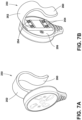
- a connection feature 250 includes a flexible hook 252.
- the flexible hook 252 includes mechanical fasteners 254 that are secured to a back side 256 of the housing 12 of the mattress state indicator 10 or to the housing 102 of the mattress state indicator 100.
- the flexible hook 252 includes a rounded body that works in a similar fashion to the spring steel clamp 172 set forth in FIGS. 5A and 5B .
- FIG. 7C clearly illustrates the mattress state indicator 10 utilizing the flexible hook 252 and connecting the mattress state indicator 10 to a lower portion of the footboard 30 of the hospital bed 22.
- connection feature 275 which includes a lower bracket 280 that may also be secured on the mattress state indicator 100, as shown, or the mattress state indicator 10 to the lower frame 32 of the hospital bed 22.
- the lower bracket 280 may be mechanically fastened to the mattress state indicator 100, adhered to the mattress state indicator 100 (or the mattress state indicator 10), or magnetically coupled to mattress state indicator 100 (or the mattress state indicator 10), for example. It will generally be contemplated that the lower bracket 280 will be mechanically fastened to the lower frame 32 of the hospital bed 22.
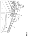
- connection feature 300 which includes a bracket 302, which is disposed above the lower frame 32 of the hospital bed 22.
- the bracket 302 works in a similar fashion to that set forth in FIG. 8 , and includes a base 304 operably coupled with the frame 32.
- the bracket 302 may interface with the mattress state indicator 10 (or the mattress state indicator 100) via magnet, adhesive, mechanical fasteners, etc.
- another connection feature 325 includes magnets 330 that are disposed on a top portion of the mattress state indicator.
- the mattress state indicator is secured to the lower frame 32 of the hospital bed 22 by magnetically coupling the top portion of the mattress state indicator proximate the magnets 330 rather than, for example, by the back side 256 of the housing 12 of the mattress state indicator 10. Consequently, the mattress state indicator will frequently be placed underneath the lower frame 32 or other metallic structure of the hospital bed 22 so as to provide a line of sight to the front side of the housing 12 which includes the display 14 of the mattress state indicator.
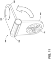
- a connection feature 350 for use with a mattress state indicator includes first and second arms 352, 354 that are connected by a rotary friction joint 356.
- the rotary friction joint 356 may be spring loaded to urge the first and second arms 352, 354 together.
- a magnet 360 is disposed on both sides of the second arm 354 and is configured to secure the mattress state indicator to the hospital bed 22 via a magnetic coupling.
- the first arm 352 is integral with the mattress state indicator and shows the display 14 which is configured to provide information to a caregiver regarding the status of the mattress state indicator.
- the present disclosure sets forth various constructions for a mattress state indicator.
- the mattress state indicator is generally configured to provide visual information to a caregiver. However, it is also contemplated that the mattress state indicator may also provide audible information (a sound or alert) that may provide information to a caregiver related to the operation state of the mattress of the hospital bed 22.
- the display 14 may also include an interface configured to receive input from a user.
- the display 14 may also include a graphical user interface with a dynamic icon that may blink at a predetermined rate.
- the display 14 may include a multitude of visual indicia 16 that can be lit in sequence thereby giving the appearance of a rotating fan to a caregiver. In this instance, the rotating fan would indicate that the mattress operation state is active.
- the dynamic icon may be lit in a predetermined sequence of long and short blinks to identify to a caregiver failure of the mattress to operate effectively.
- the blink rate may indicate the existence of a product failure or an otherwise compromised state of the mattress to function as intended.
- the visual indicia 16 may also be operable to provide different color light outputs depending on the mattress operation state. For example, if there is an error or if attention needs to be brought to the operation state of the mattress, the visual indicia 16 may illuminate in an amber color.
- the display 14 or the display 124 may include an icon that illuminates in a first color to indicate that the mattress is in a first operation state. Similarly, the icon of the display 14 or the display 124 may illuminate in a second color to indicate that the mattress is in a second operation state. If the display 14 or the display 124 is not illuminated at all, then it will be understood that the mattress is not currently operating. It will be understood by one having ordinary skill in the art that a variety of different visual indicators may be available and provided on the display 14.
- the mattress state indicator 10 or the mattress state indicator 100 may be backlit and have a varying output depending on whether the display 14 is in a standby mode condition or in an active condition.
- the display 14 of the mattress state indicator 10 or the display 124 of the mattress state indicator 100 may be backlit by the light source 18 operable between a standby condition and an active condition brightness.
- the display 14 may include various input capabilities. For example, it is generally contemplated that activation or deactivation of a mattress fan may be set at the mattress state indicator. In this instance, the display 14 may include a capacitive touch or push-push button assembly, for example, that allows a caregiver to activate or deactivate the mattress fan. Other interface options are also possible.
- the term "coupled” in all of its forms, couple, coupling, coupled, etc. generally means the joining of two components (electrical or mechanical) directly or indirectly to one another. Such joining may be stationary in nature or movable in nature. Such joining may be achieved with the two components (electrical or mechanical) and any additional intermediate members being integrally formed as a single unitary body with one another or with the two components. Such joining may be permanent in nature or may be removable or releasable in nature unless otherwise stated.
- elements shown as integrally formed may be constructed of multiple parts, or elements shown as multiple parts may be integrally formed, the operation of the interfaces may be reversed or otherwise varied, the length or width of the structures and/or members or connector or other elements of the system may be varied, the nature or number of adjustment positions provided between the elements may be varied.
- the elements and/or assemblies of the system may be constructed from any of a wide variety of materials that provide sufficient strength or durability, in any of a wide variety of colors, textures, and combinations. Substitutions, modifications, changes, and omissions may be made in the design, operating conditions, and arrangement of the desired and other exemplary embodiments.
Landscapes
- Health & Medical Sciences (AREA)
- Life Sciences & Earth Sciences (AREA)
- Animal Behavior & Ethology (AREA)
- Veterinary Medicine (AREA)
- Public Health (AREA)
- General Health & Medical Sciences (AREA)
- Nursing (AREA)
- Pathology (AREA)
- Medical Informatics (AREA)
- Molecular Biology (AREA)
- Surgery (AREA)
- Heart & Thoracic Surgery (AREA)
- Biomedical Technology (AREA)
- Engineering & Computer Science (AREA)
- Physics & Mathematics (AREA)
- Biophysics (AREA)
- Invalid Beds And Related Equipment (AREA)
Abstract
Description
- The present disclosure generally relates to a medical equipment status indicator, and more specifically to a medical equipment status indicator for use with a mattress to provide indication of a mattress operation state.
- According to one aspect of the present disclosure, a mattress state indicator includes a housing. The mattress state indicator also includes a display supported by the housing. The display is configured to provide visual indicia of a mattress operation state of a mattress. The display includes a light source disposed proximate the display. A connection feature is engaged with the housing. The connection feature is configured to couple the housing with a bed.
- According to another aspect of the present disclosure, a mattress state indicator includes a housing. A display is supported by the housing and is configured to provide visual indicia of a mattress operation state of a mattress. The display includes a light source disposed proximate the display. A bracket is engaged with the housing and includes a clamp that applies a compressive force against a portion of a bed.
- According to yet another aspect of the present disclosure, a mattress state indicator assembly includes a housing and a display that provides visual indicia of an operation state of a mattress. The display communicates wirelessly with a controller of a bed that controls the operation state of the mattress. A connector is disposed within the housing and engages a complementary connector disposed within the bed.
- The invention will now be further described by way of example with reference to the accompanying drawings, in which:
-
FIG. 1A is a top perspective view of a medical equipment status indicator removably coupled with a footboard of a hospital bed; -
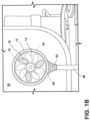
FIG. 1B is a front elevational view of a medical equipment status indicator of the present disclosure; -
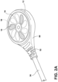
FIG. 2A is a top perspective view of a medical equipment status indicator, of the present disclosure, prior to engagement with a hospital bed; -
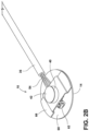
FIG. 2B is a top perspective view of a medical equipment status indicator, of the present disclosure, with a housing of the medical equipment status indicator removed; -
FIG. 2C is an enlarged top perspective cross-sectional view of a medical equipment status indicator of the present disclosure; -
FIG. 3A is a top perspective view of a medical equipment status indicator, of the present disclosure, prior to placement of a display thereon; -
FIG. 3B is a top perspective exploded view of a medical equipment status indicator of the present disclosure; -
FIG. 4A is a side perspective exploded view of a medical equipment status indicator, of the present disclosure, prior to installation; -
FIG. 4B is a top perspective view of a footboard of a hospital bed illustrating various connection features for securing a medical equipment status indicator to the footboard; -
FIG. 5A is a front perspective view of a clamp used to secure a medical equipment status indicator to a hospital bed; -
FIG. 5B is a rear perspective view of a clamp used to secure a medical equipment status indicator to a hospital bed; -
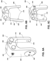
FIG. 6A is a front perspective view of another clamp used to secure a medical equipment status indicator to a hospital bed; -
FIG. 6B is a side elevational view of a clamp used to secure a medical equipment status indicator to a hospital bed; -
FIG. 6C is a rear perspective view of another clamp used to secure a medical equipment status indicator to a hospital bed; -
FIG. 7A is a top front perspective view of another connection feature for a medical equipment status indicator of the present disclosure; -
FIG. 7B is a top rear perspective view of another connection feature for a medical equipment status indicator of the present disclosure; -
FIG. 7C illustrates the connection feature ofFIG. 7B , securing the medical equipment status indicator to a footboard of a hospital bed; -
FIG. 8 illustrates another connection feature used to secure a medical equipment status indicator to a hospital bed; -
FIG. 9 illustrates yet another connection feature that can be used to secure a medical equipment status indicator to a hospital bed; -
FIG. 10 illustrates yet another connection feature that can be used to secure a medical equipment status indicator to a hospital bed; and -
FIG. 11 is a top perspective view of a medical equipment status indicator of the present disclosure. - For purposes of description herein, the terms "upper," "lower," "right," "left," "rear," "front," "vertical," "horizontal," and derivatives thereof, shall relate to the disclosure as oriented in
FIG. 1A . Unless stated otherwise, the term "front" shall refer to a surface of the device closest to an intended viewer, and the term "rear" shall refer to a surface of the device furthest from the intended viewer. However, it is to be understood that the disclosure may assume various alternative orientations, except where expressly specified to the contrary. It is also to be understood that the specific devices and processes illustrated in the attached drawings, and described in the following specification are simply exemplary embodiments. Hence, specific dimensions and other physical characteristics relating to the embodiments disclosed herein are not to be considered as limiting. - The terms "including," "comprises," "comprising," or any other variation thereof, are intended to cover a non-exclusive inclusion, such that a process, method, article, or apparatus that comprises a list of elements does not include only those elements but may include other elements not expressly listed or inherent to such process, method, article, or apparatus. An element preceded by "comprises a ... " does not, without more constraints, preclude the existence of additional identical elements in the process, method, article, or apparatus that comprises the element.
- Referring to
FIGS. 1A-11 ,reference numeral 10 generally designates a medical equipment status indicator in the form of a mattress state indicator including ahousing 12. Themattress state indicator 10 also includes adisplay 14 supported by thehousing 12. Thedisplay 14 is configured to providevisual indicia 16 of a mattress operation state of a mattress. Thedisplay 14 includes alight source 18 disposed proximate thedisplay 14. Aconnection feature 20 is engaged with thehousing 12. Theconnection feature 20 is configured to couple thehousing 12 with abed 22, such as a hospital bed. - With reference again to
FIGS. 1A and1B , themattress state indicator 10 is configured for use with thehospital bed 22 to provide a quick and efficient visual indication to a caregiver of an operation status of the mattress of thehospital bed 22. It is generally contemplated that themattress state indicator 10 will provide visual confirmation of an operation state that may include client management features, such as micro-climate management. It is generally contemplated that visual indication of the operation state of thehospital bed 22 can be provided, without the need for interactive interfaces such as buttons or switches. With themattress state indicator 10 attached to thehospital bed 22, caregivers can confirm the proper operation of the mattress frequently in order to maximize effective use of the mattress and reduce the likelihood of skin breakdown, which could lead to lesions or sores. Additionally, caregivers should be able to view the operation state of the mattress from an easily viewable location such as afootboard 30. To that end, themattress state indicator 10 should be positioned in a location that is visually non-obstructive and that does not interfere with other forms of patient care. Themattress state indicator 10 may be operably coupled with any portion of thehospital bed 22, however, inFIG. 1A , themattress state indicator 10 is illustrated as being operably coupled with thefootboard 30 above aframe 32 of thehospital bed 22. Themattress state indicator 10 may be coupled with thehospital bed 22 via various attachment methods. For example, themattress state indicator 10 may be magnetically coupled with thefootboard 30 of thehospital bed 22 by a magnetic member (another magnet or a metal that attracts a magnet). Themattress state indicator 10 in conjunction with a complementary connection feature on ahospital bed 22 defines a mattress state indicator assembly. - With reference now to
FIGS. 1A-2C , themattress state indicator 10 may also be attached to acord 36 that allows themattress state indicator 10 to be placed on either side of thefootboard 30 without dragging thecord 36 on the floor. Thecord 36 provides electrical communication (power and/or data) between thedisplay 14 and a controller of thebed 22. However, it is also contemplated that thedisplay 14 may communicate wirelessly with the controller that is configured to adjust the mattress operation state. Amagnet 40 is disposed inside thehousing 12 of themattress state indicator 10 and has afirst side 42 that is attached to a magnetic feature in the form of a metal disk orcomplementary magnet 44. It is generally contemplated that thefirst side 42 of themagnet 40 may include a polarity that is opposite that of thecomplementary magnet 44. The magnetic feature may be adhesively attached to thefootboard 30 or mounted with a mechanical fastener to thefootboard 30 of thebed 22. Alternatively, the magnetic feature may be embedded in thefootboard 30 during manufacturing of thefootboard 30. In this instance, an indicia or symbol may be disposed on an external surface of thefootboard 30 to indicate where the magnetized feature is embedded within thefootboard 30. Other methods for connection are set forth herein. - The
mattress state indicator 10 includes thedisplay 14 that may be illuminated to provide thevisual indicia 16 associated with the operation state of the mattress. Thedisplay 14 may include a variety of light sources, such as light emitting diodes (LEDs). The LEDs may be designed to operate with multiple circuits such that the LEDs may provide the appearance of motion, flashing, color, etc. In addition, the LEDs may be side-lit so as to reduce the overall thickness of themattress state indicator 10 thereby providing a lean, aesthetically pleasing profile. It will be understood that themattress state indicator 10 may be easily removed from thefootboard 30 of thebed 22 to allow repositioning, cleaning, etc. - With reference again to
FIGS. 2A-2C , aperipheral portion 50 of thehousing 12 may include a molded-instrain relief member 52 to minimize excessive strain where electrical and data wiring enters thehousing 12 of themattress state indicator 10. Although thehousing 12 is shown with a circular construction, it will also be understood that thehousing 12 may take on a variety of other constructions, including square, rectangular, etc. - With reference again to
FIG. 2B , themattress state indicator 10 is illustrated with thehousing 12 removed. Thecord 36 is shown withwiring 54 that provides electrical communication to a printed circuit board (PCB) 60 by way of anelectrical plug 62. In the construction ofFIG. 2B , thewiring 54 extends past themagnet 40 such that theelectrical plug 62 is disposed on an opposite side of themattress state indicator 10 than where thewiring 54 enters themattress state indicator 10. Theelectrical plug 62 may provide power or data to thePCB 60 or both power and data to thePCB 60 of themattress state indicator 10. ThePCB 60 is operably coupled with thedisplay 14, which as previously noted, may include a variety of light sources. In addition, a back side of thePCB 60 includes abracket 66. Thebracket 66 is operably coupled with themagnet 40 which is disposed within thehousing 12. Thebracket 66 may support themagnet 40 and also act as a radio frequency (RF) shield for thePCB 60. Themagnet 40 is configured for magnetically securing themattress state indicator 10 to a complementary magnetized feature of thehospital bed 22. As previously noted, the magnetized feature may be a metal plate, or may be anothermagnet 44 with a pole opposite to that of thefirst side 42 of themagnet 40, such that themagnet 44 and thefirst side 42 are attracted to one another. Further, the magnetized feature may be disposed interior to or exterior to a portion of thehospital bed 22. - With reference again to
FIG. 2C , themagnet 40 is clearly disposed adjacent to arear surface 70 of thehousing 12. Therear surface 70 may be surrounded by aperipheral rim 72 configured to receive a metal plate (FIG. 4A ) that is magnetically attached to themagnet 40 adjacent therear surface 70. In this case, theperipheral rim 72 serves as a locating feature that properly locates thehousing 12 against a metal plate or metal plate location on thehospital bed 22. In addition, it can be seen that thedisplay 14 includes anouter edge 78 that is over-molded by thehousing 12. Accordingly, thehousing 12 protects theouter edge 78 of thedisplay 14 from damage. - With reference now to
FIGS. 3A and 3B , in another aspect of the present disclosure, amattress state indicator 100 includes ahousing 102 having a clamshell type configuration. The clamshell configuration includes afirst housing portion 104 that is operably coupled to asecond housing portion 106 bymechanical fasteners 110. Themechanical fasteners 110 extend through receivingapertures 116 and are securely received intobosses 118. In this instance, thewiring 54 does not extend past themagnet 112, but instead is proximate anopening 113 of thehousing 102. Amagnet 112 is disposed in thesecond housing portion 106 and is located within aninternal ring 114 that properly locates themagnet 112 relative to thesecond housing portion 106. After thefirst housing portion 104 and thesecond housing portion 106 are mechanically connected, and themagnet 112 is secured within theinternal ring 114, theelectrical plug 62, which is in electrical communication with thewiring 54, can be inserted into thehousing 102 and coupled withcircuitry 120 that is operably coupled with adisplay 124. Thedisplay 124 is secured to thefirst housing portion 104. Thedisplay 124 may be secured by adhesive, for example. It will be understood that thedisplay 124 includes the same or similar features as thedisplay 14 as set forth herein. - It is generally contemplated, regardless of the construction of the mattress state indicator, that the mattress state indicator will be operably coupled with the
hospital bed 22. In one instance, as shown inFIG. 4A , aconnection feature 150 includes anadhesive ring 152 that acts as an interface between a metal plate 154 (which, alternatively, could be a complementary magnet) and thefootboard 30 of thehospital bed 22. Amechanical fastener 156 extends through afastener aperture 158 in themetal plate 154 and a label ordecal 160 is positioned over themetal plate 154. This construction is configured to interface with themagnet 40 of themattress state indicator 10 or themagnet 112 of themattress state indicator 100. Themechanical fastener 156 secures themetal plate 154 to thefootboard 30 and theadhesive ring 152 prevents rotation of themetal plate 154 relative to thefootboard 30. - With reference now to
FIG. 4B , themattress state indicator 10 may also be secured to thefootboard 30 by less permanent coupling assemblies. The coupling assemblies may include clamps that are secured to a portion of thefootboard 30 or other areas of thehospital bed 22. In these instances, the clamps may be removed from thehospital bed 22 quickly and easily, without permanently marking or damaging thehospital bed 22. - With reference now to
FIGS. 5A and 5B , an instance of aconnection feature 170 in the form of a bracket is illustrated. Theconnection feature 170 illustrates aspring steel clamp 172 including first andsecond arms intermediate portion 178. An outside surface of thefirst arm 174 includes ametal plate 180, or any other known magnetic member, configured to interface with themagnet 40 of themattress state indicator 10 or themagnet 112 of themattress state indicator 100. An inside surface of thefirst arm 174 includes apliable engagement member 181 made of a highly frictional polymer, for example, that assists in frictionally securing theconnection feature 170 to a portion of thehospital bed 22. Thesecond arm 176 is turned slightly inward and includes a spring biased arrangement configured to frictionally engage a portion of thehospital bed 22, such as thefootboard 30. Thus, the spring steel claim is configured to apply a compressive force against a portion of thehospital bed 22. Abottom end 182 of thesecond arm 176 defines an outwardly extending tab configured to allow a caregiver to pull thesecond arm 176 away from thefirst arm 174, thereby releasing thespring steel clamp 172 from thehospital bed 22. Thespring steel clamp 172 can then be relocated or moved to adifferent hospital bed 22. The space between the first andsecond arms footboard 30, for example) of thehospital bed 22. - With reference now to
FIGS. 6A-6C , anotherconnection feature 200 in the form of a bracket is illustrated, which includes anadjustable clamp 202, which may be constructed from a polymeric material such as plastic. Theadjustable clamp 202 includes first and second downwardly extendingarms pivot pin 208. Thepivot pin 208 allows for the first and second downwardly extendingarms bolt 210 extends through first and second threadeddowels 212 disposed inside each of the first and second downwardly extendingarms dowels 212 may be made from a variety of materials such as, for example, metal. The threadedbolt 210 may be tightened, by a tool or by hand, such that theadjustable clamp 202 tightly engages thehospital bed 22. An inside surface of each of the first and second downwardly extendingarms pliable material 216 configured to engage thehospital bed 22 without placing undue stress on either theadjustable clamp 202 or thehospital bed 22. In addition, ametal plate 220, or other magnetic member, is disposed on an outside surface of the first downwardly extendingarm 204 and is configured for interface with themagnet 40 of themattress state indicator 10 or themagnet 112 of themattress state indicator 100. - With reference now to
FIGS. 7A and 7B , in another construction, aconnection feature 250 includes aflexible hook 252. Theflexible hook 252 includesmechanical fasteners 254 that are secured to aback side 256 of thehousing 12 of themattress state indicator 10 or to thehousing 102 of themattress state indicator 100. Theflexible hook 252 includes a rounded body that works in a similar fashion to thespring steel clamp 172 set forth inFIGS. 5A and 5B . When removal of the mattress state indicator 10 (or the mattress state indicator 100) from thehospital bed 22 is desired, a caregiver simply pulls alower end 260 of theflexible hook 252 away from the mattress state indicator 10 (or the mattress state indicator 100) and repositions the mattress state indicator 10 (or the mattress state indicator 100) on a different location of thehospital bed 22 or removes the mattress state indicator from thehospital bed 22 altogether.FIG. 7C clearly illustrates themattress state indicator 10 utilizing theflexible hook 252 and connecting themattress state indicator 10 to a lower portion of thefootboard 30 of thehospital bed 22. - With reference now to
FIG. 8 ,connection feature 275 is illustrated which includes alower bracket 280 that may also be secured on themattress state indicator 100, as shown, or themattress state indicator 10 to thelower frame 32 of thehospital bed 22. In this instance, thelower bracket 280 may be mechanically fastened to themattress state indicator 100, adhered to the mattress state indicator 100 (or the mattress state indicator 10), or magnetically coupled to mattress state indicator 100 (or the mattress state indicator 10), for example. It will generally be contemplated that thelower bracket 280 will be mechanically fastened to thelower frame 32 of thehospital bed 22. - With reference now to
FIG. 9 , anotherconnection feature 300 is illustrated which includes abracket 302, which is disposed above thelower frame 32 of thehospital bed 22. Thebracket 302 works in a similar fashion to that set forth inFIG. 8 , and includes a base 304 operably coupled with theframe 32. Thebracket 302 may interface with the mattress state indicator 10 (or the mattress state indicator 100) via magnet, adhesive, mechanical fasteners, etc. - With reference now to
FIG. 10 , anotherconnection feature 325 includesmagnets 330 that are disposed on a top portion of the mattress state indicator. In this instance, the mattress state indicator is secured to thelower frame 32 of thehospital bed 22 by magnetically coupling the top portion of the mattress state indicator proximate themagnets 330 rather than, for example, by theback side 256 of thehousing 12 of themattress state indicator 10. Consequently, the mattress state indicator will frequently be placed underneath thelower frame 32 or other metallic structure of thehospital bed 22 so as to provide a line of sight to the front side of thehousing 12 which includes thedisplay 14 of the mattress state indicator. - With reference now to
FIG. 11 , in another aspect of the present disclosure, aconnection feature 350 for use with a mattress state indicator includes first andsecond arms second arms magnet 360 is disposed on both sides of thesecond arm 354 and is configured to secure the mattress state indicator to thehospital bed 22 via a magnetic coupling. Thefirst arm 352 is integral with the mattress state indicator and shows thedisplay 14 which is configured to provide information to a caregiver regarding the status of the mattress state indicator. - The present disclosure sets forth various constructions for a mattress state indicator. The mattress state indicator is generally configured to provide visual information to a caregiver. However, it is also contemplated that the mattress state indicator may also provide audible information (a sound or alert) that may provide information to a caregiver related to the operation state of the mattress of the
hospital bed 22. Thedisplay 14 may also include an interface configured to receive input from a user. Thedisplay 14 may also include a graphical user interface with a dynamic icon that may blink at a predetermined rate. For example, thedisplay 14 may include a multitude ofvisual indicia 16 that can be lit in sequence thereby giving the appearance of a rotating fan to a caregiver. In this instance, the rotating fan would indicate that the mattress operation state is active. It is also contemplated that the dynamic icon may be lit in a predetermined sequence of long and short blinks to identify to a caregiver failure of the mattress to operate effectively. For example, the blink rate may indicate the existence of a product failure or an otherwise compromised state of the mattress to function as intended. - In addition, the
visual indicia 16 may also be operable to provide different color light outputs depending on the mattress operation state. For example, if there is an error or if attention needs to be brought to the operation state of the mattress, thevisual indicia 16 may illuminate in an amber color. Thedisplay 14 or thedisplay 124 may include an icon that illuminates in a first color to indicate that the mattress is in a first operation state. Similarly, the icon of thedisplay 14 or thedisplay 124 may illuminate in a second color to indicate that the mattress is in a second operation state. If thedisplay 14 or thedisplay 124 is not illuminated at all, then it will be understood that the mattress is not currently operating. It will be understood by one having ordinary skill in the art that a variety of different visual indicators may be available and provided on thedisplay 14. - In addition, the
mattress state indicator 10 or themattress state indicator 100 may be backlit and have a varying output depending on whether thedisplay 14 is in a standby mode condition or in an active condition. Stated differently, thedisplay 14 of themattress state indicator 10 or thedisplay 124 of themattress state indicator 100 may be backlit by thelight source 18 operable between a standby condition and an active condition brightness. Moreover, thedisplay 14 may include various input capabilities. For example, it is generally contemplated that activation or deactivation of a mattress fan may be set at the mattress state indicator. In this instance, thedisplay 14 may include a capacitive touch or push-push button assembly, for example, that allows a caregiver to activate or deactivate the mattress fan. Other interface options are also possible. - For purposes of this disclosure, the term "coupled" (in all of its forms, couple, coupling, coupled, etc.) generally means the joining of two components (electrical or mechanical) directly or indirectly to one another. Such joining may be stationary in nature or movable in nature. Such joining may be achieved with the two components (electrical or mechanical) and any additional intermediate members being integrally formed as a single unitary body with one another or with the two components. Such joining may be permanent in nature or may be removable or releasable in nature unless otherwise stated.
- It is also important to note that the construction and arrangement of the elements of the disclosure, as shown in the exemplary embodiments, is illustrative only. Although only a few embodiments of the present innovations have been described in detail in this disclosure, those skilled in the art who review this disclosure will readily appreciate that many modifications are possible (e.g., variations in sizes, dimensions, structures, shapes and proportions of the various elements, values of parameters, mounting arrangements, use of materials, colors, orientations, etc.) without materially departing from the novel teachings and advantages of the subject matter recited. For example, elements shown as integrally formed may be constructed of multiple parts, or elements shown as multiple parts may be integrally formed, the operation of the interfaces may be reversed or otherwise varied, the length or width of the structures and/or members or connector or other elements of the system may be varied, the nature or number of adjustment positions provided between the elements may be varied. It should be noted that the elements and/or assemblies of the system may be constructed from any of a wide variety of materials that provide sufficient strength or durability, in any of a wide variety of colors, textures, and combinations. Substitutions, modifications, changes, and omissions may be made in the design, operating conditions, and arrangement of the desired and other exemplary embodiments.
- It will be understood that any described processes or steps within described processes may be combined with other disclosed processes or steps to form structures within the scope of the present disclosure. The exemplary structures and processes disclosed herein are for illustrative purposes and are not to be construed as limiting.
- Embodiments of the invention can be described with reference to the following numbered clauses, with preferred features laid out in the dependent clauses:
- 1. A mattress state indicator comprising: a housing; a display supported by the housing and configured to provide visual indicia of a mattress operation state of a mattress, wherein the display includes a light source disposed proximate the display; and a bracket engaged with the housing, the bracket including a clamp that applies a compressive force against a portion of a bed.
- 2. The mattress state indicator of
clause 1, wherein the clamp is a spring steel clamp that includes first and second arms, and wherein one of the first arm and the second arm includes a pliable engagement member on an inside surface and a magnetic member on an outside surface. - 3. The mattress state indicator of either
clause 1 or clause 2, wherein the clamp includes a threaded engagement member configured to draw first and second arms of the clamp together. - 4. The mattress state indicator of clause 3, wherein the clamp includes first and second threaded dowels that extend through the first and second arms, and which receive the threaded engagement member.
- 5. A mattress state indicator assembly, comprising: a housing; a display that provides visual indicia of an operation state of a mattress, wherein the display communicates wirelessly with a controller of a bed that controls the operation state of the mattress; and a connector disposed within the housing and which engages a complementary connector disposed within the bed.
- 6. The mattress state indicator assembly of clause 5, wherein the complementary connector is embedded within a footboard of the bed.
- 7. The mattress state indicator assembly of either clause 5 or clause 6, wherein a dynamic icon blinks in a sequence of long and short blinks to identify a mattress operation state failure.
- 8. A mattress state indicator (10) comprising:
- a housing (12);
- a display (14) supported by the housing (12) and configured to provide visual indicia (16) of an operation state of a mattress, wherein the display (14) includes a light source (18) disposed proximate the display (14); and
- a connection feature (20) engaged with the housing (12), the connection feature (20) configured to couple the housing (12) with a bed (22) to provide a caregiver a visual indication of the operation state of the mattress.
- 9. The mattress state indicator (10) of clause 8, wherein the connection feature (20) includes a magnet (40) that is disposed in the housing (12).
- 10. The mattress state indicator (10) of either of clauses 8 or 9, further comprising:
a cord (36) that couples the housing (12) to the bed (22) that provides electrical communication between the display (14) and a controller of the bed (22). - 11. The mattress state indicator (10) of any one of clauses 8-10, further comprising:
a complementary connection feature disposed within the bed (22). - 12. The mattress state indicator (10) of clause 11, wherein the complementary connection feature is embedded within a footboard (30) of the bed (22).
- 13. The mattress state indicator (10) of any one of clauses 8-12, wherein the display (14) includes an interface configured to receive input from a user.
- 14. The mattress state indicator (10) of any one of clauses 8-13, wherein the display (14) includes an icon that illuminates in a first color to indicate that the mattress is in a first operation state and illuminates in a second color to indicate that the mattress is in a second operation state.
- 15. The mattress state indicator (10) of any one of clauses 8-14, wherein the display (14) includes a graphical user interface and a dynamic icon that blinks at a predetermined rate.
- 16. The mattress state indicator (10) of clause 15, wherein the dynamic icon blinks in a sequence of long and short blinks to identify a mattress operation state failure.
- 17. The mattress state indicator (10) of any one of clauses 8-17, wherein the display (14) is backlit by the light source (18), and wherein the light source (18) is operable between an active condition brightness and a standby condition brightness.
- 18. The mattress state indicator (10) of any one of clauses 8-17, wherein the display (14) communicates wirelessly with a controller that is configured to adjust the operation state of the mattress.
- 19. The mattress state indicator (10) of any one of clauses 8-18, wherein the connection feature (20) operably couples the housing (12) with a footboard (30) of the bed (22).
- 20. The mattress state indicator (10) of any one of clauses 8-19, wherein the connection feature (20) includes a bracket (66) that operably couples the housing (12) to the bed (22).
Claims (14)
- A mattress state indicator assembly comprising:a housing (12, 102);a display (14, 124) for providing visual indicia (16) of an operation state of a mattress, wherein the display (14, 124) configured to communicate wirelessly with a controller of a bed (22) for controlling the operation state of the mattress, the display (14, 124) being configured to illuminate in a first color to indicate that the mattress is in a first operation state and illuminate in a second color to indicate that the mattress is in a second operation state; anda connector (20, 150, 170, 200, 250, 275, 300, 325, 350) disposed within the housing (12, 102) and which is configured to engage a complementary connector of the bed (22).
- The mattress state indicator assembly of claim 1, wherein the complementary connector is embedded within a footboard (30) of the bed (22).
- The mattress state indicator assembly of either one of claims 1 or 2, wherein the complementary connector includes a magnet (44, 360).
- The mattress state indicator assembly of any preceding claim, wherein a dynamic icon of the display (14, 124) is configured to blink in a sequence of long and short blinks to identify a mattress operation state failure.
- The mattress state indicator assembly of any preceding claim, wherein the display (14, 124) is backlit by a light source (18) operable between a standby condition and an active condition brightness.
- The mattress state indicator assembly of any preceding claim, wherein activation or deactivation of a mattress fan is configured to be set at the display (14, 124).
- The mattress state indicator assembly of any preceding claim, wherein the display (14, 124) includes a capacitive touch button assembly that allows a caregiver to activate or deactivate the mattress fan.
- The mattress state indicator assembly of any one of claims 1-6, wherein the display (14, 124) includes a push-push button assembly that allows a caregiver to activate or deactivate the mattress fan.
- The mattress state indicator assembly of any preceding claim, wherein the visual indicia (16) is configured to illuminate in an amber color when the mattress has an operation state error.
- The mattress state indicator assembly of any preceding claim, wherein the display (14, 124) includes a multitude of visual indicia (16) that can be lit in sequence thereby giving the appearance of a rotating fan.
- The mattress state indicator assembly of any preceding claim, wherein the connector (350) includes first and second arms (352, 354) that are connected by a rotary friction joint (356).
- The mattress state indicator assembly of claim 11, wherein the rotary friction joint (356) is spring loaded to urge the first and second arms (352, 354) together.
- The mattress state indicator assembly of either one of claims 11 or 12, wherein a magnet (360) is disposed on both sides of the second arm (354), the magnet (360) configured to secure to the bed (22) via magnetic coupling.
- The mattress state indicator assembly of any one of claims 11-13, wherein the first arm (352) is integral with the housing (12, 102) and shows the display (14, 124).
Applications Claiming Priority (3)
| Application Number | Priority Date | Filing Date | Title |
|---|---|---|---|
| US201962810565P | 2019-02-26 | 2019-02-26 | |
| US16/794,899 US12491124B2 (en) | 2019-02-26 | 2020-02-19 | Medical equipment status indicator |
| EP20159126.0A EP3701924B1 (en) | 2019-02-26 | 2020-02-24 | Medical equipment status indicator |
Related Parent Applications (2)
| Application Number | Title | Priority Date | Filing Date |
|---|---|---|---|
| EP20159126.0A Division-Into EP3701924B1 (en) | 2019-02-26 | 2020-02-24 | Medical equipment status indicator |
| EP20159126.0A Division EP3701924B1 (en) | 2019-02-26 | 2020-02-24 | Medical equipment status indicator |
Publications (3)
| Publication Number | Publication Date |
|---|---|
| EP4316443A2 true EP4316443A2 (en) | 2024-02-07 |
| EP4316443A3 EP4316443A3 (en) | 2024-02-21 |
| EP4316443B1 EP4316443B1 (en) | 2025-03-26 |
Family
ID=69953724
Family Applications (2)
| Application Number | Title | Priority Date | Filing Date |
|---|---|---|---|
| EP20159126.0A Active EP3701924B1 (en) | 2019-02-26 | 2020-02-24 | Medical equipment status indicator |
| EP23218818.5A Active EP4316443B1 (en) | 2019-02-26 | 2020-02-24 | Medical equipment status indicator |
Family Applications Before (1)
| Application Number | Title | Priority Date | Filing Date |
|---|---|---|---|
| EP20159126.0A Active EP3701924B1 (en) | 2019-02-26 | 2020-02-24 | Medical equipment status indicator |
Country Status (3)
| Country | Link |
|---|---|
| US (2) | US12491124B2 (en) |
| EP (2) | EP3701924B1 (en) |
| CN (1) | CN212788957U (en) |
Families Citing this family (2)
| Publication number | Priority date | Publication date | Assignee | Title |
|---|---|---|---|---|
| CN112998672A (en) * | 2021-03-25 | 2021-06-22 | 苏州沪应通智能科技有限公司 | Intelligent mattress with heart impact scanning sensor |
| JP2024036309A (en) * | 2022-09-05 | 2024-03-15 | キヤノンメディカルシステムズ株式会社 | Diagnostic support system and diagnostic support device |
Family Cites Families (56)
| Publication number | Priority date | Publication date | Assignee | Title |
|---|---|---|---|---|
| US1760346A (en) * | 1928-12-12 | 1930-05-27 | Frank M Correa | Bedding clamp |
| US1929657A (en) * | 1931-07-20 | 1933-10-10 | Rip Van Winkle Wall Bed Compan | Folding bed cover clamp |
| US1948965A (en) * | 1933-05-12 | 1934-02-27 | Harry B Hart | Sheet, mattress, and blanket clamp |
| US3757363A (en) * | 1970-09-10 | 1973-09-11 | J Langlais | Patient communicator support |
| US3781843A (en) * | 1971-04-15 | 1973-12-25 | Sanders Associates Inc | Bed guard system |
| US3929309A (en) * | 1974-08-26 | 1975-12-30 | Pierce Louis B | Head rest |
| US3981492A (en) * | 1975-08-04 | 1976-09-21 | Hallmann David R | X-ray table patient transfer device or the like with body holding device |
| US4346298A (en) * | 1981-03-02 | 1982-08-24 | Dixit Jagannath K | Automatic air pillow for diagnostic X-ray machine |
| US4616813A (en) * | 1984-04-10 | 1986-10-14 | Mcconnell Bernard E | Suspension for surgical support apparatus |
| US4968078A (en) * | 1989-05-24 | 1990-11-06 | Edwin Fitzwater | Adjustable compound-action clamp |
| US4913413A (en) * | 1989-06-09 | 1990-04-03 | Faro Medical Technologies Inc. | Universal leg holder |
| US5335651A (en) * | 1990-05-16 | 1994-08-09 | Hill-Rom Company, Inc. | Ventilator and care cart each capable of nesting within and docking with a hospital bed base |
| US5349340A (en) * | 1993-01-29 | 1994-09-20 | Hunter Fan Company | Portable patient alerting apparatus |
| US5404602A (en) * | 1994-01-24 | 1995-04-11 | Kondo; Victor F. | Bedclothes anchoring apparatus |
| US6023800A (en) * | 1997-05-09 | 2000-02-15 | Midmark Corporation | Removable accessory for a surgical table |
| US6014346A (en) * | 1998-02-12 | 2000-01-11 | Accucure, L.L.C. | Medical timer/monitor and method of monitoring patient status |
| US5934721A (en) * | 1998-06-03 | 1999-08-10 | Walde; Armin | Multi-function adjustable grip barbecue tong assembly |
| US6295670B1 (en) * | 2000-05-04 | 2001-10-02 | Daniel L. Schieberl | Bed covering retention apparatus |
| US6496094B2 (en) * | 2001-01-30 | 2002-12-17 | May, Iii Otho D | Magnet clamp for hand tools |
| US7027358B1 (en) * | 2003-04-28 | 2006-04-11 | Advanced Prevention Technologies Inc. | System for pressure ulcer prophylaxis and treatment |
| US7003815B2 (en) * | 2004-02-06 | 2006-02-28 | Foot Flush International, Inc. | Foot operated flushing apparatus and method |
| US7719437B2 (en) * | 2004-02-19 | 2010-05-18 | Bertram Iii Morton | Magnetic bed-rail attachment particularly suited to sterile environments |
| US7287290B2 (en) * | 2004-09-23 | 2007-10-30 | Hill-Rom Services, Inc. | Mattress having an air pressure indicator |
| US20060157996A1 (en) * | 2004-12-03 | 2006-07-20 | Rubbermaid Incorporated | Tongs |
| JP5231222B2 (en) | 2005-07-08 | 2013-07-10 | ヒル−ロム サービシーズ,インコーポレイティド | Patient support control unit |
| US11246776B2 (en) * | 2005-12-19 | 2022-02-15 | Stryker Corporation | Patient support with improved control |
| US7850302B1 (en) * | 2005-12-31 | 2010-12-14 | Shirin Riazi | Eyeglass holder with clasp |
| US8840549B2 (en) * | 2006-09-22 | 2014-09-23 | Masimo Corporation | Modular patient monitor |
| US7458622B2 (en) * | 2007-01-29 | 2008-12-02 | Trudeau Corporation | Tongs for Handling food |
| US8146599B2 (en) * | 2008-06-17 | 2012-04-03 | Civco Medical Instruments Co., Inc. | Patient positioning system |
| US8051515B1 (en) * | 2008-08-12 | 2011-11-08 | Bob Kring | Surgical bed clamp apparatus |
| US8621692B1 (en) * | 2008-08-12 | 2014-01-07 | Bob Kring | Surgical bed clamp apparatus |
| US9149211B2 (en) * | 2008-10-24 | 2015-10-06 | Sensimat Systems Inc. | Monitoring system for pressure sore prevention |
| US8752220B2 (en) * | 2009-07-10 | 2014-06-17 | Hill-Rom Services, Inc. | Systems for patient support, monitoring and treatment |
| EP2345396B1 (en) * | 2010-01-14 | 2013-05-08 | Hill-Rom Services, Inc. | Person-support apparatus height indicator |
| US8833707B2 (en) * | 2010-07-15 | 2014-09-16 | Allen Medical Systems, Inc. | Disposable urology drainage bag |
| EP2670652A4 (en) * | 2011-02-04 | 2014-05-07 | Mahindra Navistar Automotives Ltd | Auto lock stay rod for cabin of a vehicle |
| EP2766659B1 (en) * | 2011-10-09 | 2017-05-17 | Stryker Corporation | Illuminable indicator for a bed |
| US9655798B2 (en) | 2013-03-14 | 2017-05-23 | Hill-Rom Services, Inc. | Multi-alert lights for hospital bed |
| US20140345058A1 (en) * | 2013-05-21 | 2014-11-27 | SEC Medical Development, Inc. | Pressure Monitoring and Management Cushion System And Method Of Use |
| US9463126B2 (en) * | 2014-03-11 | 2016-10-11 | Hill-Rom Services, Inc. | Caregiver universal remote cart for patient bed control |
| US10638969B2 (en) * | 2014-11-10 | 2020-05-05 | Walgreens Health Solutions, LLC | Wireless pressure ulcer alert methods and systems therefor |
| EP3250113A4 (en) * | 2015-01-30 | 2018-10-03 | Huntleigh Technology Limited | Status or alarm indicator device |
| GB201512110D0 (en) * | 2015-07-10 | 2015-08-19 | Elowes Ltd | Anchoring apparatus for bedclothes |
| PL3383337T3 (en) | 2015-12-04 | 2025-08-11 | Arjo IP Holding Aktiebolag | Indicator device |
| US20170202361A1 (en) * | 2016-01-19 | 2017-07-20 | Christopher Andrew White | Bedcover securing device |
| CA3015844C (en) * | 2016-03-01 | 2022-04-12 | Motion Composites Inc | Wheelchair frame |
| US11338107B2 (en) * | 2016-08-24 | 2022-05-24 | Delos Living Llc | Systems, methods and articles for enhancing wellness associated with habitable environments |
| US11013652B1 (en) * | 2016-09-19 | 2021-05-25 | Kyra Medical, Inc | Limb holder allowing distal actuation along non-linear paths of actuation |
| SI25420A (en) * | 2017-05-09 | 2018-11-30 | Rok ColariÄŤ | Device for quick preparation of tempered drinks |
| US11337872B2 (en) * | 2017-06-27 | 2022-05-24 | Stryker Corporation | Patient support systems and methods for assisting caregivers with patient care |
| US10980689B2 (en) * | 2017-07-14 | 2021-04-20 | Stryker Corporation | Patient support apparatuses with personal electronic device charging |
| US10034679B1 (en) * | 2017-10-31 | 2018-07-31 | Boyer Anderson, LLC | Artificial prosthesis installation clamp and method |
| US20190350318A1 (en) * | 2018-05-16 | 2019-11-21 | Joseph Harris Levine | Magnetic strap |
| US10788193B2 (en) * | 2018-07-26 | 2020-09-29 | Shawn Michael Genenbacher | Removable clamp for decorative lights |
| US11058240B2 (en) * | 2019-08-13 | 2021-07-13 | Joshua Bearden | Pressure monitor pillow |
-
2020
- 2020-02-19 US US16/794,899 patent/US12491124B2/en active Active
- 2020-02-24 EP EP20159126.0A patent/EP3701924B1/en active Active
- 2020-02-24 EP EP23218818.5A patent/EP4316443B1/en active Active
- 2020-02-25 CN CN202020208183.7U patent/CN212788957U/en active Active
-
2025
- 2025-12-08 US US19/412,385 patent/US20260090932A1/en active Pending
Also Published As
| Publication number | Publication date |
|---|---|
| EP3701924B1 (en) | 2024-01-24 |
| EP4316443B1 (en) | 2025-03-26 |
| US20260090932A1 (en) | 2026-04-02 |
| EP3701924A1 (en) | 2020-09-02 |
| US12491124B2 (en) | 2025-12-09 |
| CN212788957U (en) | 2021-03-26 |
| US20200268580A1 (en) | 2020-08-27 |
| EP4316443A3 (en) | 2024-02-21 |
Similar Documents
| Publication | Publication Date | Title |
|---|---|---|
| US20260090932A1 (en) | Medical equipment status indicator | |
| US11992129B2 (en) | Bed with magnetic couplers | |
| CN104350683B (en) | Modular communication device and system | |
| JP5161112B2 (en) | Proximity detector | |
| EP3537934B1 (en) | Magnetic coupler for a bed | |
| US20160178230A1 (en) | Rotatable Wall-Mounted Thermostat Having a Leveling Feature | |
| EP2777670A1 (en) | Multi-alert lights for hospital bed | |
| US12569615B2 (en) | Medical device, method and systems | |
| CN2446955Y (en) | Wireless body temperature monitoring device | |
| EP3189778B1 (en) | Physiological status monitoring device | |
| JP2007334258A (en) | Thin display device | |
| US20220329113A1 (en) | Mobile furniture panel | |
| CN212135568U (en) | Meal selling system | |
| USD457505S1 (en) | Space saver kitchen video/CD/AM/FM stereo apparatus | |
| EP3955088A1 (en) | Docking station with detachable back support | |
| US20160093189A1 (en) | Baby Sleeping Position Reminder | |
| US11241546B2 (en) | Holder for a recording unit | |
| JP7085866B2 (en) | Medical device system | |
| JP3070840U (en) | Tabletop hand-held electric controller | |
| US20240263767A1 (en) | Lighting assembly and illumination system having a lighting assembly | |
| CN215603884U (en) | monitoring desk | |
| JP5966130B2 (en) | In-vehicle equipment attachment | |
| JP3168237U (en) | Electrical equipment | |
| JP2006102378A (en) | Nurse call device | |
| TW202032868A (en) | Improvements in circuit identification on wall mounted electrical outlets and switch plates |
Legal Events
| Date | Code | Title | Description |
|---|---|---|---|
| PUAI | Public reference made under article 153(3) epc to a published international application that has entered the european phase |
Free format text: ORIGINAL CODE: 0009012 |
|
| STAA | Information on the status of an ep patent application or granted ep patent |
Free format text: STATUS: THE APPLICATION HAS BEEN PUBLISHED |
|
| PUAL | Search report despatched |
Free format text: ORIGINAL CODE: 0009013 |
|
| AC | Divisional application: reference to earlier application |
Ref document number: 3701924 Country of ref document: EP Kind code of ref document: P |
|
| AK | Designated contracting states |
Kind code of ref document: A2 Designated state(s): AL AT BE BG CH CY CZ DE DK EE ES FI FR GB GR HR HU IE IS IT LI LT LU LV MC MK MT NL NO PL PT RO RS SE SI SK SM TR |
|
| AK | Designated contracting states |
Kind code of ref document: A3 Designated state(s): AL AT BE BG CH CY CZ DE DK EE ES FI FR GB GR HR HU IE IS IT LI LT LU LV MC MK MT NL NO PL PT RO RS SE SI SK SM TR |
|
| RIC1 | Information provided on ipc code assigned before grant |
Ipc: A61G 7/05 20060101AFI20240116BHEP |
|
| STAA | Information on the status of an ep patent application or granted ep patent |
Free format text: STATUS: REQUEST FOR EXAMINATION WAS MADE |
|
| 17P | Request for examination filed |
Effective date: 20240821 |
|
| RBV | Designated contracting states (corrected) |
Designated state(s): AL AT BE BG CH CY CZ DE DK EE ES FI FR GB GR HR HU IE IS IT LI LT LU LV MC MK MT NL NO PL PT RO RS SE SI SK SM TR |
|
| GRAP | Despatch of communication of intention to grant a patent |
Free format text: ORIGINAL CODE: EPIDOSNIGR1 |
|
| STAA | Information on the status of an ep patent application or granted ep patent |
Free format text: STATUS: GRANT OF PATENT IS INTENDED |
|
| INTG | Intention to grant announced |
Effective date: 20241023 |
|
| GRAS | Grant fee paid |
Free format text: ORIGINAL CODE: EPIDOSNIGR3 |
|
| GRAA | (expected) grant |
Free format text: ORIGINAL CODE: 0009210 |
|
| STAA | Information on the status of an ep patent application or granted ep patent |
Free format text: STATUS: THE PATENT HAS BEEN GRANTED |
|
| RAP3 | Party data changed (applicant data changed or rights of an application transferred) |
Owner name: HILL-ROM SERVICES, INC. |
|
| RIN1 | Information on inventor provided before grant (corrected) |
Inventor name: FISK, BRANDON Inventor name: GUTHRIE, BRIAN Inventor name: MEYER, ERIC R. Inventor name: NEWKIRK, DAVID |
|
| AC | Divisional application: reference to earlier application |
Ref document number: 3701924 Country of ref document: EP Kind code of ref document: P |
|
| AK | Designated contracting states |
Kind code of ref document: B1 Designated state(s): AL AT BE BG CH CY CZ DE DK EE ES FI FR GB GR HR HU IE IS IT LI LT LU LV MC MK MT NL NO PL PT RO RS SE SI SK SM TR |
|
| REG | Reference to a national code |
Ref country code: GB Ref legal event code: FG4D |
|
| REG | Reference to a national code |
Ref country code: CH Ref legal event code: EP |
|
| P01 | Opt-out of the competence of the unified patent court (upc) registered |
Free format text: CASE NUMBER: APP_10117/2025 Effective date: 20250227 |
|
| REG | Reference to a national code |
Ref country code: DE Ref legal event code: R096 Ref document number: 602020048577 Country of ref document: DE |
|
| REG | Reference to a national code |
Ref country code: IE Ref legal event code: FG4D |
|
| PG25 | Lapsed in a contracting state [announced via postgrant information from national office to epo] |
Ref country code: RS Free format text: LAPSE BECAUSE OF FAILURE TO SUBMIT A TRANSLATION OF THE DESCRIPTION OR TO PAY THE FEE WITHIN THE PRESCRIBED TIME-LIMIT Effective date: 20250626 |
|
| PG25 | Lapsed in a contracting state [announced via postgrant information from national office to epo] |
Ref country code: FI Free format text: LAPSE BECAUSE OF FAILURE TO SUBMIT A TRANSLATION OF THE DESCRIPTION OR TO PAY THE FEE WITHIN THE PRESCRIBED TIME-LIMIT Effective date: 20250326 |
|
| REG | Reference to a national code |
Ref country code: LT Ref legal event code: MG9D |
|
| PG25 | Lapsed in a contracting state [announced via postgrant information from national office to epo] |
Ref country code: NO Free format text: LAPSE BECAUSE OF FAILURE TO SUBMIT A TRANSLATION OF THE DESCRIPTION OR TO PAY THE FEE WITHIN THE PRESCRIBED TIME-LIMIT Effective date: 20250626 |
|
| PG25 | Lapsed in a contracting state [announced via postgrant information from national office to epo] |
Ref country code: HR Free format text: LAPSE BECAUSE OF FAILURE TO SUBMIT A TRANSLATION OF THE DESCRIPTION OR TO PAY THE FEE WITHIN THE PRESCRIBED TIME-LIMIT Effective date: 20250326 |
|
| PG25 | Lapsed in a contracting state [announced via postgrant information from national office to epo] |
Ref country code: LV Free format text: LAPSE BECAUSE OF FAILURE TO SUBMIT A TRANSLATION OF THE DESCRIPTION OR TO PAY THE FEE WITHIN THE PRESCRIBED TIME-LIMIT Effective date: 20250326 |
|
| PG25 | Lapsed in a contracting state [announced via postgrant information from national office to epo] |
Ref country code: GR Free format text: LAPSE BECAUSE OF FAILURE TO SUBMIT A TRANSLATION OF THE DESCRIPTION OR TO PAY THE FEE WITHIN THE PRESCRIBED TIME-LIMIT Effective date: 20250627 Ref country code: BG Free format text: LAPSE BECAUSE OF FAILURE TO SUBMIT A TRANSLATION OF THE DESCRIPTION OR TO PAY THE FEE WITHIN THE PRESCRIBED TIME-LIMIT Effective date: 20250326 |
|
| REG | Reference to a national code |
Ref country code: NL Ref legal event code: MP Effective date: 20250326 |
|
| PG25 | Lapsed in a contracting state [announced via postgrant information from national office to epo] |
Ref country code: NL Free format text: LAPSE BECAUSE OF FAILURE TO SUBMIT A TRANSLATION OF THE DESCRIPTION OR TO PAY THE FEE WITHIN THE PRESCRIBED TIME-LIMIT Effective date: 20250326 |
|
| PG25 | Lapsed in a contracting state [announced via postgrant information from national office to epo] |
Ref country code: SE Free format text: LAPSE BECAUSE OF FAILURE TO SUBMIT A TRANSLATION OF THE DESCRIPTION OR TO PAY THE FEE WITHIN THE PRESCRIBED TIME-LIMIT Effective date: 20250326 |
|
| REG | Reference to a national code |
Ref country code: AT Ref legal event code: MK05 Ref document number: 1778338 Country of ref document: AT Kind code of ref document: T Effective date: 20250326 |
|
| PG25 | Lapsed in a contracting state [announced via postgrant information from national office to epo] |
Ref country code: SM Free format text: LAPSE BECAUSE OF FAILURE TO SUBMIT A TRANSLATION OF THE DESCRIPTION OR TO PAY THE FEE WITHIN THE PRESCRIBED TIME-LIMIT Effective date: 20250326 |
|
| PG25 | Lapsed in a contracting state [announced via postgrant information from national office to epo] |
Ref country code: ES Free format text: LAPSE BECAUSE OF FAILURE TO SUBMIT A TRANSLATION OF THE DESCRIPTION OR TO PAY THE FEE WITHIN THE PRESCRIBED TIME-LIMIT Effective date: 20250326 Ref country code: PT Free format text: LAPSE BECAUSE OF FAILURE TO SUBMIT A TRANSLATION OF THE DESCRIPTION OR TO PAY THE FEE WITHIN THE PRESCRIBED TIME-LIMIT Effective date: 20250728 |
|
| PG25 | Lapsed in a contracting state [announced via postgrant information from national office to epo] |
Ref country code: IT Free format text: LAPSE BECAUSE OF FAILURE TO SUBMIT A TRANSLATION OF THE DESCRIPTION OR TO PAY THE FEE WITHIN THE PRESCRIBED TIME-LIMIT Effective date: 20250326 Ref country code: PL Free format text: LAPSE BECAUSE OF FAILURE TO SUBMIT A TRANSLATION OF THE DESCRIPTION OR TO PAY THE FEE WITHIN THE PRESCRIBED TIME-LIMIT Effective date: 20250326 |
|
| PG25 | Lapsed in a contracting state [announced via postgrant information from national office to epo] |
Ref country code: AT Free format text: LAPSE BECAUSE OF FAILURE TO SUBMIT A TRANSLATION OF THE DESCRIPTION OR TO PAY THE FEE WITHIN THE PRESCRIBED TIME-LIMIT Effective date: 20250326 |
|
| PG25 | Lapsed in a contracting state [announced via postgrant information from national office to epo] |
Ref country code: EE Free format text: LAPSE BECAUSE OF FAILURE TO SUBMIT A TRANSLATION OF THE DESCRIPTION OR TO PAY THE FEE WITHIN THE PRESCRIBED TIME-LIMIT Effective date: 20250326 |
|
| PG25 | Lapsed in a contracting state [announced via postgrant information from national office to epo] |
Ref country code: RO Free format text: LAPSE BECAUSE OF FAILURE TO SUBMIT A TRANSLATION OF THE DESCRIPTION OR TO PAY THE FEE WITHIN THE PRESCRIBED TIME-LIMIT Effective date: 20250326 |
|
| PG25 | Lapsed in a contracting state [announced via postgrant information from national office to epo] |
Ref country code: SK Free format text: LAPSE BECAUSE OF FAILURE TO SUBMIT A TRANSLATION OF THE DESCRIPTION OR TO PAY THE FEE WITHIN THE PRESCRIBED TIME-LIMIT Effective date: 20250326 |
|
| PG25 | Lapsed in a contracting state [announced via postgrant information from national office to epo] |
Ref country code: IS Free format text: LAPSE BECAUSE OF FAILURE TO SUBMIT A TRANSLATION OF THE DESCRIPTION OR TO PAY THE FEE WITHIN THE PRESCRIBED TIME-LIMIT Effective date: 20250726 |
|
| REG | Reference to a national code |
Ref country code: DE Ref legal event code: R097 Ref document number: 602020048577 Country of ref document: DE |
|
| PG25 | Lapsed in a contracting state [announced via postgrant information from national office to epo] |
Ref country code: DK Free format text: LAPSE BECAUSE OF FAILURE TO SUBMIT A TRANSLATION OF THE DESCRIPTION OR TO PAY THE FEE WITHIN THE PRESCRIBED TIME-LIMIT Effective date: 20250326 |
|
| PG25 | Lapsed in a contracting state [announced via postgrant information from national office to epo] |
Ref country code: CZ Free format text: LAPSE BECAUSE OF FAILURE TO SUBMIT A TRANSLATION OF THE DESCRIPTION OR TO PAY THE FEE WITHIN THE PRESCRIBED TIME-LIMIT Effective date: 20250326 |
|
| PLBE | No opposition filed within time limit |
Free format text: ORIGINAL CODE: 0009261 |
|
| STAA | Information on the status of an ep patent application or granted ep patent |
Free format text: STATUS: NO OPPOSITION FILED WITHIN TIME LIMIT |
|
| REG | Reference to a national code |
Ref country code: CH Ref legal event code: L10 Free format text: ST27 STATUS EVENT CODE: U-0-0-L10-L00 (AS PROVIDED BY THE NATIONAL OFFICE) Effective date: 20260211 |
|
| 26N | No opposition filed |
Effective date: 20260105 |
|
| PGFP | Annual fee paid to national office [announced via postgrant information from national office to epo] |
Ref country code: GB Payment date: 20260122 Year of fee payment: 7 |
|
| PGFP | Annual fee paid to national office [announced via postgrant information from national office to epo] |
Ref country code: DE Payment date: 20260121 Year of fee payment: 7 |
|
| PGFP | Annual fee paid to national office [announced via postgrant information from national office to epo] |
Ref country code: FR Payment date: 20260121 Year of fee payment: 7 |
|
| PG25 | Lapsed in a contracting state [announced via postgrant information from national office to epo] |
Ref country code: LT Free format text: LAPSE BECAUSE OF FAILURE TO SUBMIT A TRANSLATION OF THE DESCRIPTION OR TO PAY THE FEE WITHIN THE PRESCRIBED TIME-LIMIT Effective date: 20250326 |