EP4316413B1 - Device for the retraction of soft tissue in a patient undergoing arthroscopic surgery - Google Patents
Device for the retraction of soft tissue in a patient undergoing arthroscopic surgery Download PDFInfo
- Publication number
- EP4316413B1 EP4316413B1 EP23218218.8A EP23218218A EP4316413B1 EP 4316413 B1 EP4316413 B1 EP 4316413B1 EP 23218218 A EP23218218 A EP 23218218A EP 4316413 B1 EP4316413 B1 EP 4316413B1
- Authority
- EP
- European Patent Office
- Prior art keywords
- pulling element
- soft tissue
- presser body
- presser
- patient
- Prior art date
- Legal status (The legal status is an assumption and is not a legal conclusion. Google has not performed a legal analysis and makes no representation as to the accuracy of the status listed.)
- Active
Links
Images



Classifications
-
- A—HUMAN NECESSITIES
- A61—MEDICAL OR VETERINARY SCIENCE; HYGIENE
- A61B—DIAGNOSIS; SURGERY; IDENTIFICATION
- A61B17/00—Surgical instruments, devices or methods
- A61B17/02—Surgical instruments, devices or methods for holding wounds open, e.g. retractors; Tractors
- A61B17/0218—Surgical instruments, devices or methods for holding wounds open, e.g. retractors; Tractors for minimally invasive surgery
-
- A—HUMAN NECESSITIES
- A61—MEDICAL OR VETERINARY SCIENCE; HYGIENE
- A61B—DIAGNOSIS; SURGERY; IDENTIFICATION
- A61B17/00—Surgical instruments, devices or methods
- A61B17/02—Surgical instruments, devices or methods for holding wounds open, e.g. retractors; Tractors
- A61B17/0281—Abdominal wall lifters
-
- A—HUMAN NECESSITIES
- A61—MEDICAL OR VETERINARY SCIENCE; HYGIENE
- A61B—DIAGNOSIS; SURGERY; IDENTIFICATION
- A61B17/00—Surgical instruments, devices or methods
- A61B17/00234—Surgical instruments, devices or methods for minimally invasive surgery
- A61B2017/00292—Surgical instruments, devices or methods for minimally invasive surgery mounted on or guided by flexible, e.g. catheter-like, means
- A61B2017/003—Steerable
- A61B2017/00318—Steering mechanisms
- A61B2017/00323—Cables or rods
-
- A—HUMAN NECESSITIES
- A61—MEDICAL OR VETERINARY SCIENCE; HYGIENE
- A61B—DIAGNOSIS; SURGERY; IDENTIFICATION
- A61B17/00—Surgical instruments, devices or methods
- A61B2017/00367—Details of actuation of instruments, e.g. relations between pushing buttons, or the like, and activation of the tool, working tip, or the like
- A61B2017/00407—Ratchet means
-
- A—HUMAN NECESSITIES
- A61—MEDICAL OR VETERINARY SCIENCE; HYGIENE
- A61B—DIAGNOSIS; SURGERY; IDENTIFICATION
- A61B17/00—Surgical instruments, devices or methods
- A61B17/28—Surgical forceps
- A61B2017/2808—Clamp, e.g. towel clamp
-
- A—HUMAN NECESSITIES
- A61—MEDICAL OR VETERINARY SCIENCE; HYGIENE
- A61B—DIAGNOSIS; SURGERY; IDENTIFICATION
- A61B17/00—Surgical instruments, devices or methods
- A61B17/28—Surgical forceps
- A61B17/29—Forceps for use in minimally invasive surgery
- A61B2017/2926—Details of heads or jaws
- A61B2017/2932—Transmission of forces to jaw members
- A61B2017/2944—Translation of jaw members
-
- A—HUMAN NECESSITIES
- A61—MEDICAL OR VETERINARY SCIENCE; HYGIENE
- A61B—DIAGNOSIS; SURGERY; IDENTIFICATION
- A61B90/00—Instruments, implements or accessories specially adapted for surgery or diagnosis and not covered by any of the groups A61B1/00 - A61B50/00, e.g. for luxation treatment or for protecting wound edges
- A61B90/03—Automatic limiting or abutting means, e.g. for safety
- A61B2090/033—Abutting means, stops, e.g. abutting on tissue or skin
- A61B2090/034—Abutting means, stops, e.g. abutting on tissue or skin abutting on parts of the device itself
Definitions
- the present invention relates to a device for the retraction of soft tissue in a patient undergoing arthroscopic surgery.
- the present invention finds particular application in the surgical field, preferably the orthopaedic field, in tissue fixation equipment and in the preparation of the area to be operated.
- retraction instruments which, by means of special curved blades, cling to the edges of the wound from which the surgical tools are inserted, moving them away from each other.
- These blades usually have a geometry such as to move not only the skin of the patient, but also the layers of soft tissue immediately adjacent thereto, so as to "open” the view to the surgeon.
- Langenbeck retractor for example, has a second end positioned at right angles to the elongated central structure, while Volkmann retractor has a second end at an angle of about 180 degrees with respect to the elongated central structure and connected thereto by means of a curved portion.
- said retractors are not easy to use in minimally invasive surgery, since their constructional features require a space for access to the operative site that is oversized compared to the minimally invasive surgery techniques.
- the instrument known as the Leroy retractor comprises an axially elongated structure with two free ends: a first one with a handle and a second with a variable geometry. In non-use conditions, the second end is axially aligned with the elongated structure.
- the surgeon by means of a suitable command, can bend the second end up to an angle of 90 degrees with respect to the elongated structure, so as to intercept the soft tissue. At this point, by traction, the surgeon can remove the soft tissue from the operative site.
- Leroy retractor is specially designed for laparoscopic operations.
- this type of minimally invasive surgery especially in colorectal laparoscopic surgery, a difficult anatomy (especially in obese male patients) makes it essential to use retractors to be able to clearly distinguish the different structures and make the intervention, for example the dissection, possible.
- Leroy retractors provide the possibility of having numerous configurations of the second free end, such as, for example, T-shaped ends, H-shaped ends, or the like.
- US 2005/251159 A1 relates to apparatus and methods for positioning and securing anchors within tissue, such as folds of tissue within a body.
- EP 3 245 956 A2 forms prior art according to Art. 54(3) EPC and relates to a capsular retractor, to retract capsular tissue for better visualization during joint repair.
- a further object of the present invention is to provide a device for the retraction of soft tissue, which is easily adjustable and easy to use.
- the retraction device comprises a pulling element extending in its own main direction between a first end and a second end.
- the second end is fitted with a hooking body configured to pass through the soft tissue of a patient and engage (or intercept) said soft tissue following the traction of the pulling element towards the first end.
- the device further comprises a presser body adapted to press on the skin of said patient and connectable to the pulling element in at least one operating position placed at a fixed distance from the second end.
- the fixed distance is such as to define a housing for the layers of the patient's soft tissue engaged by the hooking body, so as to compress it and consequently create the operative space between the bone and the tissue.
- the presser body 3 is connected to the pulling element 2 so as to define therewith a clamp in which the soft tissues ST are compressed.
- the retraction of the soft tissue comprises limiting the distal displacement of the skin from the bone portion by means of a presser body abutted against the skin of the patient and compressing the layers of soft tissue towards said presser body (i.e. away from the bone but without traction) so as to create an operative space.
- the efficiency of the operation can be combined with a reduced invasiveness of the same, which helps to reduce the patients' recovery time.
- the presser body is slidingly joined to the pulling element to move from a rest position, distal to the second end, to said operating position, proximal to the second end.
- blocking means are provided which are configured to prevent the presser body from moving away from the second end when in said operating position, thus allowing the correct compression of the tissues interposed between the presser body and the hooking body.
- the unidirectional sliding and blocking are obtained by means of a ratchet coupling of the presser body on the pulling element.
- the presser body has a pincer or clothes peg shape so as to be able to couple to and uncouple from the pulling element following a (manual) command given by the operator.
- the numeral 1 indicates a device for the retraction of soft tissue in a patient undergoing arthroscopic surgery according to the present invention.
- soft tissues is intended to mean all such tissues with a density different from that of the bone and therefore distinguishable and separable from the bone.
- soft tissues can be one or more of the following:
- the device 1 finds application in the creation of a gap or a distance between the bone "B” and the soft tissue "ST" during a surgical, preferably orthopaedic operation, more preferably an arthroscopy.
- the device 1 preferably comprises a pulling element 2 and a presser body 3.
- the pulling element 2 extends along its own main direction "A" between a first end 2a and a second end 2b.
- the first end 2a is free and can be gripped or manoeuvred by an operator, i.e. the surgeon.
- the first end 2a is provided with a handle 15, in order to assist the surgeon in manoeuvring the device 1.
- the second end 2b is fitted with a hooking body 4 configured to pass through the patient's soft tissue "ST" and engage the same following the traction of the pulling element 2 towards the first end 2a.
- the hooking body 4 is shaped so that, once inserted through the soft tissues "ST” by moving it proximally (i.e. towards the bone), it can intercept the soft tissues "ST", pushing them distally (i.e. away from the bone) when the pulling element is moved in the direction of the first end 2a.
- the pulling element 2 comprises a stem 5 extending along the main direction "A" between its own first 5a and its own second 5b end portion.
- the end portions 5a, 5b of the stem substantially correspond to the ends 2a, 2b of the pulling element 2.
- the hooking body 4 is joined to the second end portion 5b of the stem 5.
- the hooking body 4 is rotatably joined to the stem 5, at the second end portion 5b (i.e. the second end of the pulling element 2).
- the hooking body 4 can rotate so as to move between a first position, in which it is substantially aligned with the stem 5, and a second position, in which it is substantially transverse to the stem 5 (i.e. to the main direction "A").
- the hooking body 4 is pivoted (preferably at a central portion thereof) to the second end portion 5b of the stem 5.
- the pulling element 2 can easily penetrate the skin “S”, passing through the soft tissues "ST”, with the hooking body 4 in the first position.
- the hooking body 4 preferably comprises a tapered end portion 4a so that, when it is in said first position, it defines with the stem 5 an instrument able to penetrate the soft tissue "ST" of the patient.
- the pulling element 2 comprises a manoeuvring group 6 operable by an operator and joined to the hooking body 4.
- This manoeuvring group 6 is configured to move the hooking body 4 between the first and the second position.
- the manoeuvring group 6 preferably comprises a control body 6a, manoeuvrable by the operator, and a transmission member 6b operatively interposed between the control body 6a and the hooking body 4.
- the surgeon by acting manually on the control body 6a can thus move the hooking body 4 between the first and the second position.
- the transmission member 6b comprises a rod (or a cable) 7 slidingly inserted in the stem 5 and connected to the hooking body 4.
- this rod (or cable) 7 is connected to the hooking body 4 so that a translation thereof corresponds to a rotation of the hooking body 4.
- control body 6a is a ring nut or sleeve movable by the surgeon towards or away from the first end 2a of the pulling element 2 in order to move the transmission member 6b.
- control body 6a is a ring nut, its translation is obtained by means of a threaded coupling to the stem 5 and the rotation thereof.
- control body 6a is a sleeve (shown)
- its translation occurs directly, by means of a pushing or pulling action by the surgeon.
- the device 1 also comprises a presser body 3 joined to the pulling element 2.
- the presser body 3 is adapted to press on the skin "S" of the patient and connectable to the pulling element 2 in at least one operating position placed at a fixed distance "d" from the second end 2a.
- This fixed distance “d” is such as to define a housing for the layers of soft tissue "ST" of the patient engaged by the hooking body 4.
- the presser body 4 is connected to the pulling element 2 so as to define therewith a clamp in which the soft tissues "ST" are compressed, in order to detach them from the bone.
- the operating position (and hence the distance d) is variable and adjustable according to the thickness of the patient's soft tissues "ST", which may be of different levels proportionally to the thickness of the tendons, muscles and fatty layer.
- the presser body 3 is preferably slidingly joined to the pulling element 2 to move from a rest position, distal to the second end 2a, to said operating position, proximal to the second end 2b.
- the device 1 comprises blocking means 8 operatively interposed between said presser body 3 and the pulling element 2.
- the blocking means 8 are configured to prevent the presser body 3 from moving away from the second end 2b when said presser body 3 is in said operating position.
- the presser body 3 is preferably slidingly joined to the pulling element 2 unidirectionally, i.e. free to slide from the first end 2a to the second end 2b.
- the blocking means 8 prevent sliding in the opposite direction.
- the presser body 3 is slidingly joined to the pulling element 2 by means of a tightener group 9.
- This tightener group 9 is configured to allow an increase in the contact pressure between the presser body 3 and the skin "S" of the patient, at least when the presser body 3 is in the operating position.
- the tightener group 9 comprises a ratchet coupling.
- the ratchet coupling comprises a plurality of abutment shoulders 10 arranged in succession along the pulling element 2 (defining said blocking means 8) and at least one abutment tooth 11 joined to the presser body 3.
- the abutment tooth 11 is shaped to slide along the pulling element 2 (and along the abutment shoulders 10) from the first 2a to the second 2b end and halt against the abutment shoulders 10 if moved from the second 2b to the first 2a end.
- the pulling element 2 (in particular the stem 5) has a sawtooth side profile.
- each tooth extends gradually away from the stem 5 towards the second end 5b and allows the tooth 11 of the presser body 3 to slide in this direction.
- each tooth extends substantially perpendicular from the top to the stem 5, defining an abutment shoulder 10 and preventing the tooth 11 of the presser body 3 from sliding away from the second end 5b.
- said presser body 3 has a pincer or clothes peg shape.
- the presser body 3 comprises two jaws 12 reciprocally moving towards and away from each other between a juxtaposed position, defining said engaged condition, and a distant position, defining said disengaged condition.
- the presser body 3 has a normally closed configuration in which the jaws 12 are in the juxtaposed position (i.e. in the engaged condition).
- the jaws 12 are therefore maintained in the juxtaposed position by elastic means.
- the presser body 3 In order to move the presser body 3 between the two positions, it is provided with a pair of movement arms 13, each joined to a respective jaw 12, reciprocally moving towards and away from each other between a proximal position, in which they keep the jaws 12 spaced apart in the distant position corresponding to the normally closed configuration of the presser body 3.
- a fulcrum 14 which allows the movement to be transferred from one to the other (defining a first class lever).
- the fulcrum 14 therefore defines a deformable elastic means which allows the jaws 12 to be opened/closed, keeping them in the juxtaposed position in the absence of external stresses.
- the device 1 (but not exclusively), it is therefore possible to implement an innovative method of retraction of soft tissue in a patient undergoing arthroscopic surgery.
- This method comprises incising and penetrating one or more layers of soft tissue "ST” proximal to a bone portion "B” to be operated and retracting said layers of soft tissue “ST” away from the bone portion "B” in order to create a space in the operative site.
- the retraction of the soft tissues "ST” is obtained by limiting the distal displacement of the skin “S” from the bone portion "B” by means of a presser body 3 abutted against the skin “S” and compressing said one or more layers of soft tissue “ST” towards said presser body 3 so as to create a space in the operative site.
- the tendons and all the tissues are preserved as no traction is exerted thereon (or only to a very small extent) when they move away from the bone.
- the compression is in fact achieved by tightening the presser body 3, abutted externally against the skin "S”, against a pulling element 2 fitted with at least one hooking body 4 inserted through said one or more layers of soft tissue "ST".
- the presser body 3 and the pulling element 2 are of the type described previously with regard to the device 1 object of the present invention.
- the invention achieves the intended objects and attains important advantages.
- the presence of a ratchet coupling or a tightener group between the presser body and the pulling element is particularly advantageous since it allows the "operating position" to be adapted to the individual patient without the need for dedicated devices.
Landscapes
- Health & Medical Sciences (AREA)
- Life Sciences & Earth Sciences (AREA)
- Surgery (AREA)
- Heart & Thoracic Surgery (AREA)
- Engineering & Computer Science (AREA)
- Biomedical Technology (AREA)
- Nuclear Medicine, Radiotherapy & Molecular Imaging (AREA)
- Medical Informatics (AREA)
- Molecular Biology (AREA)
- Animal Behavior & Ethology (AREA)
- General Health & Medical Sciences (AREA)
- Public Health (AREA)
- Veterinary Medicine (AREA)
- Surgical Instruments (AREA)
Description
- The present invention relates to a device for the retraction of soft tissue in a patient undergoing arthroscopic surgery.
- Therefore, the present invention finds particular application in the surgical field, preferably the orthopaedic field, in tissue fixation equipment and in the preparation of the area to be operated.
- In the context of surgical interventions intended to restore the normal articular mobility of an articulation of the human body, it is well known to arrange the operative site for the subsequent operations of restoration of the articular functionality. Because of the human anatomy, the preparation of the operative site requires the displacement of the soft tissue from its natural position adjacent to the patient's bone structure. This operation takes place by making an incision in the skin of the patient, creating therein an access for the entry of a special instrument, known as a retractor.
- Currently, in order to increase the visibility, retraction instruments are used which, by means of special curved blades, cling to the edges of the wound from which the surgical tools are inserted, moving them away from each other.
- These blades usually have a geometry such as to move not only the skin of the patient, but also the layers of soft tissue immediately adjacent thereto, so as to "open" the view to the surgeon.
- Langenbeck and Volkmann retractors are cited merely as examples of retractors known in the state of the art.
- Langenbeck retractor, for example, has a second end positioned at right angles to the elongated central structure, while Volkmann retractor has a second end at an angle of about 180 degrees with respect to the elongated central structure and connected thereto by means of a curved portion.
- The use of such instruments derives directly from their function. After making an incision for access to the operative site, the retractor is inserted, the curved portion intercepting the soft tissue, thus moving it away from the proximity of the bone structure.
- As will be easily recognized, said retractors are not easy to use in minimally invasive surgery, since their constructional features require a space for access to the operative site that is oversized compared to the minimally invasive surgery techniques.
- Therefore, when the surgeon operates in minimally invasive situations, it is necessary to use retractors having variable geometry, so as to facilitate their insertion in the operative site. In fact, in operations of this type, the size of the access to the operative site is minimized as much as possible so as to inflict a small wound on the patient. This type of approach, however, does not allow the surgeon to have a good room for manoeuvre for operating by means of surgical instruments designed for a classic approach, for example an open surgery.
- An example of a known retractor for minimally invasive surgery is the instrument known as the Leroy retractor. This device comprises an axially elongated structure with two free ends: a first one with a handle and a second with a variable geometry. In non-use conditions, the second end is axially aligned with the elongated structure. Once the instrument is inserted in the operative site, the surgeon, by means of a suitable command, can bend the second end up to an angle of 90 degrees with respect to the elongated structure, so as to intercept the soft tissue. At this point, by traction, the surgeon can remove the soft tissue from the operative site.
- Leroy retractor is specially designed for laparoscopic operations. In this type of minimally invasive surgery, especially in colorectal laparoscopic surgery, a difficult anatomy (especially in obese male patients) makes it essential to use retractors to be able to clearly distinguish the different structures and make the intervention, for example the dissection, possible.
- Because of the particular nature of the type of surgery for which they are designed, Leroy retractors provide the possibility of having numerous configurations of the second free end, such as, for example, T-shaped ends, H-shaped ends, or the like.
- However, during arthroscopy operations, the surgeon's needs are not simply to remove the soft tissue, as in the case of laparoscopy, but most closely match the needs of an open surgery, despite the fact that they are minimally invasive operations. In fact, during arthroscopic surgery, the surgeon needs to remove the soft tissue from the patient's bone structure in order to be able to access it and operate therein. As mentioned, however, the spaces are very narrow and the operative site cannot be accessed with typical instruments for open surgery.
- It is also crucial for the surgeon not only to be able to remove the soft tissue from the bone structure, but also to reduce its dimensions in the whereabouts of the operative site, in order to facilitate the operation.
US 2005/251159 A1 relates to apparatus and methods for positioning and securing anchors within tissue, such as folds of tissue within a body. -
EP 3 245 956 A2 - From the above, it therefore appears that the aforesaid objects cannot be achieved by means of equipment known in the state of the art, since, even though with arthroscopy access to the operative site with known instruments is hypothetically possible, it would not be possible to effectively remove the soft tissue from the bone structure.
- Therefore, it is an object of the present invention to provide a device for the retraction of soft tissue in a patient undergoing arthroscopic surgery, which overcomes the above-mentioned drawbacks of the prior art.
- In particular, it is an object of the present invention to provide a device for the retraction of soft tissue in a patient undergoing arthroscopic surgery, which is able to create the required operative space without compromising the integrity of the patient's soft tissue.
- A further object of the present invention is to provide a device for the retraction of soft tissue, which is easily adjustable and easy to use.
- Said objects are achieved by means of a device for the retraction of soft tissue having the features of one or more of the ensuing claims.
- In particular, the retraction device comprises a pulling element extending in its own main direction between a first end and a second end.
- Preferably, the second end is fitted with a hooking body configured to pass through the soft tissue of a patient and engage (or intercept) said soft tissue following the traction of the pulling element towards the first end.
- According to one aspect of the present invention, the device further comprises a presser body adapted to press on the skin of said patient and connectable to the pulling element in at least one operating position placed at a fixed distance from the second end.
- Preferably, the fixed distance is such as to define a housing for the layers of the patient's soft tissue engaged by the hooking body, so as to compress it and consequently create the operative space between the bone and the tissue.
- Therefore, the
presser body 3 is connected to the pullingelement 2 so as to define therewith a clamp in which the soft tissues ST are compressed. - Advantageously, thanks to this device, no traction is exerted any more on the soft tissue moving away from the bone, but said tissue is compressed so as to reduce the thickness thereof, which brings about the detachment of tendons and muscle bundles atraumatically.
- In particular, thanks to this device, it is possible to implement a retraction method innovative per se, according to which the retraction of the soft tissue comprises limiting the distal displacement of the skin from the bone portion by means of a presser body abutted against the skin of the patient and compressing the layers of soft tissue towards said presser body (i.e. away from the bone but without traction) so as to create an operative space.
- Advantageously, thanks to this innovative principle, the efficiency of the operation can be combined with a reduced invasiveness of the same, which helps to reduce the patients' recovery time.
- It should preferably be noted that the presser body is slidingly joined to the pulling element to move from a rest position, distal to the second end, to said operating position, proximal to the second end.
- More preferably, blocking means are provided which are configured to prevent the presser body from moving away from the second end when in said operating position, thus allowing the correct compression of the tissues interposed between the presser body and the hooking body.
- In the preferred embodiment, the unidirectional sliding and blocking are obtained by means of a ratchet coupling of the presser body on the pulling element.
- Preferably, moreover, the presser body has a pincer or clothes peg shape so as to be able to couple to and uncouple from the pulling element following a (manual) command given by the operator.
- These and other features and the inherent advantages will become more apparent from the following illustrative, therefore non-limiting, description of a preferred, thus not exclusive, embodiment of a device for the retraction of soft tissue in a patient undergoing arthroscopic surgery as shown in the accompanying drawings, wherein:
-
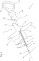
Figures 1 and2 show two perspective, front and rear views of a device for the retraction of soft tissue in a patient undergoing arthroscopic surgery according to the present invention; -
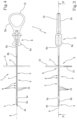
Figures 3 and 4 show a plan view and the corresponding longitudinal section of the device inFigure 1 ; -
Figures 5a-5c show successive steps of a method of retraction of soft tissue in a patient undergoing arthroscopic surgery implemented by means of the device ofFigure 1 . - With reference to the accompanying figures, the
numeral 1 indicates a device for the retraction of soft tissue in a patient undergoing arthroscopic surgery according to the present invention. - It should be noted that in the present text "soft tissues" is intended to mean all such tissues with a density different from that of the bone and therefore distinguishable and separable from the bone.
- By way of example, soft tissues can be one or more of the following:
- muscles,
- tendons,
- fat,
- synovia,
- vessels,
- nerves,
- connective tissue proper or interstitial tissue (supporting the parenchyma),
- supportive connective tissue, such as for example cartilages.
- Therefore, the
device 1 finds application in the creation of a gap or a distance between the bone "B" and the soft tissue "ST" during a surgical, preferably orthopaedic operation, more preferably an arthroscopy. - The
device 1 preferably comprises apulling element 2 and apresser body 3. - The pulling
element 2 extends along its own main direction "A" between afirst end 2a and asecond end 2b. - Preferably, the
first end 2a is free and can be gripped or manoeuvred by an operator, i.e. the surgeon. - In the illustrated embodiment, the
first end 2a is provided with ahandle 15, in order to assist the surgeon in manoeuvring thedevice 1. - Also preferably, the
second end 2b, instead, is fitted with a hookingbody 4 configured to pass through the patient's soft tissue "ST" and engage the same following the traction of the pullingelement 2 towards thefirst end 2a. - In other words, the hooking
body 4 is shaped so that, once inserted through the soft tissues "ST" by moving it proximally (i.e. towards the bone), it can intercept the soft tissues "ST", pushing them distally (i.e. away from the bone) when the pulling element is moved in the direction of thefirst end 2a. - In the preferred embodiment, the pulling
element 2 comprises astem 5 extending along the main direction "A" between its own first 5a and its own second 5b end portion. - The
end portions ends element 2. - Therefore, the hooking
body 4 is joined to thesecond end portion 5b of thestem 5. - Preferably, the hooking
body 4 is rotatably joined to thestem 5, at thesecond end portion 5b (i.e. the second end of the pulling element 2). - In particular, the hooking
body 4 can rotate so as to move between a first position, in which it is substantially aligned with thestem 5, and a second position, in which it is substantially transverse to the stem 5 (i.e. to the main direction "A"). - In the preferred embodiment, the hooking
body 4 is pivoted (preferably at a central portion thereof) to thesecond end portion 5b of thestem 5. - Advantageously, in this way, the pulling
element 2 can easily penetrate the skin "S", passing through the soft tissues "ST", with the hookingbody 4 in the first position. - In this regard, the hooking
body 4 preferably comprises atapered end portion 4a so that, when it is in said first position, it defines with thestem 5 an instrument able to penetrate the soft tissue "ST" of the patient. - By moving the hooking
body 4 into the second position, instead, a non-extractable anchor is obtained which, with the body penetrated inside the soft tissues "ST", intercepts them; as a result of a movement or traction of the pullingelement 2 in the direction of thefirst end 2a, therefore, the hookingbody 4 in the second position retracts the soft tissues "ST" away from the bone, thus creating space in the operative site. - In order to allow the hooking
body 4 to be moved easily, the pullingelement 2 comprises amanoeuvring group 6 operable by an operator and joined to the hookingbody 4. - This
manoeuvring group 6 is configured to move the hookingbody 4 between the first and the second position. - More precisely, the
manoeuvring group 6 preferably comprises acontrol body 6a, manoeuvrable by the operator, and atransmission member 6b operatively interposed between thecontrol body 6a and the hookingbody 4. - Advantageously, the surgeon by acting manually on the
control body 6a can thus move the hookingbody 4 between the first and the second position. - In the preferred embodiment, the
transmission member 6b comprises a rod (or a cable) 7 slidingly inserted in thestem 5 and connected to the hookingbody 4. - In particular, this rod (or cable) 7 is connected to the hooking
body 4 so that a translation thereof corresponds to a rotation of the hookingbody 4. - In this regard, preferably, the
control body 6a is a ring nut or sleeve movable by the surgeon towards or away from thefirst end 2a of the pullingelement 2 in order to move thetransmission member 6b. - If the
control body 6a is a ring nut, its translation is obtained by means of a threaded coupling to thestem 5 and the rotation thereof. - If the
control body 6a is a sleeve (shown), its translation occurs directly, by means of a pushing or pulling action by the surgeon. - In order to allow the correct retraction of the soft tissue "ST", as said, the
device 1 also comprises apresser body 3 joined to the pullingelement 2. - According to one aspect of the present invention, the
presser body 3 is adapted to press on the skin "S" of the patient and connectable to the pullingelement 2 in at least one operating position placed at a fixed distance "d" from thesecond end 2a. - This fixed distance "d" is such as to define a housing for the layers of soft tissue "ST" of the patient engaged by the hooking
body 4. - In other words, the
presser body 4 is connected to the pullingelement 2 so as to define therewith a clamp in which the soft tissues "ST" are compressed, in order to detach them from the bone. - Preferably, the operating position (and hence the distance d) is variable and adjustable according to the thickness of the patient's soft tissues "ST", which may be of different levels proportionally to the thickness of the tendons, muscles and fatty layer.
- In this regard, the
presser body 3 is preferably slidingly joined to the pullingelement 2 to move from a rest position, distal to thesecond end 2a, to said operating position, proximal to thesecond end 2b. - In order to maintain the position, and hence the pressure that allows the tissues to be compressed, the
device 1 comprises blocking means 8 operatively interposed between saidpresser body 3 and the pullingelement 2. - The blocking means 8 are configured to prevent the
presser body 3 from moving away from thesecond end 2b when saidpresser body 3 is in said operating position. - Therefore, the
presser body 3 is preferably slidingly joined to the pullingelement 2 unidirectionally, i.e. free to slide from thefirst end 2a to thesecond end 2b. - The blocking means 8 prevent sliding in the opposite direction.
- Preferentially, the
presser body 3 is slidingly joined to the pullingelement 2 by means of atightener group 9. - This
tightener group 9 is configured to allow an increase in the contact pressure between thepresser body 3 and the skin "S" of the patient, at least when thepresser body 3 is in the operating position. - In the preferred embodiment, the
tightener group 9 comprises a ratchet coupling. - More precisely, the ratchet coupling comprises a plurality of abutment shoulders 10 arranged in succession along the pulling element 2 (defining said blocking means 8) and at least one
abutment tooth 11 joined to thepresser body 3. - The
abutment tooth 11 is shaped to slide along the pulling element 2 (and along the abutment shoulders 10) from the first 2a to the second 2b end and halt against the abutment shoulders 10 if moved from the second 2b to the first 2a end. - In the preferred embodiment, the pulling element 2 (in particular the stem 5) has a sawtooth side profile.
- The inclined surface of each tooth extends gradually away from the
stem 5 towards thesecond end 5b and allows thetooth 11 of thepresser body 3 to slide in this direction. - The steep surface of each tooth extends substantially perpendicular from the top to the
stem 5, defining anabutment shoulder 10 and preventing thetooth 11 of thepresser body 3 from sliding away from thesecond end 5b. - Preferably, moreover, the
presser body 3 is selectively switchable between an engaged condition, in which it is slidingly connected to the pullingelement 2, and a disengaged condition, in which it is releasable (or released) from the pullingelement 2. - Advantageously, in this way, once the operation is terminated or in case of necessary and further adjustments, it is possible to detach the
presser body 3 from the pullingelement 2, for example by moving the presser body away from thesecond end 2b (which would not be possible in the engaged condition). - In the preferred embodiment, in order to allow such switching, said
presser body 3 has a pincer or clothes peg shape. - More precisely, the
presser body 3 comprises twojaws 12 reciprocally moving towards and away from each other between a juxtaposed position, defining said engaged condition, and a distant position, defining said disengaged condition. - In the juxtaposed position, between the two
jaws 12 there is a gap for the passage of the pullingelement 2; said gap is peripherally bounded by an edge defining theabutment tooth 11. - It should be noted that, preferably, the
presser body 3 has a normally closed configuration in which thejaws 12 are in the juxtaposed position (i.e. in the engaged condition). - Preferably, the
jaws 12 are therefore maintained in the juxtaposed position by elastic means. - In order to move the
presser body 3 between the two positions, it is provided with a pair ofmovement arms 13, each joined to arespective jaw 12, reciprocally moving towards and away from each other between a proximal position, in which they keep thejaws 12 spaced apart in the distant position corresponding to the normally closed configuration of thepresser body 3. - In other words, between the
arms 13 and thejaws 12 there is a fulcrum 14 which allows the movement to be transferred from one to the other (defining a first class lever). - The fulcrum 14 therefore defines a deformable elastic means which allows the
jaws 12 to be opened/closed, keeping them in the juxtaposed position in the absence of external stresses. - Thanks to the device 1 (but not exclusively), it is therefore possible to implement an innovative method of retraction of soft tissue in a patient undergoing arthroscopic surgery.
- This method comprises incising and penetrating one or more layers of soft tissue "ST" proximal to a bone portion "B" to be operated and retracting said layers of soft tissue "ST" away from the bone portion "B" in order to create a space in the operative site.
- According to this innovative method, the retraction of the soft tissues "ST" is obtained by limiting the distal displacement of the skin "S" from the bone portion "B" by means of a
presser body 3 abutted against the skin "S" and compressing said one or more layers of soft tissue "ST" towards saidpresser body 3 so as to create a space in the operative site. - Advantageously, the tendons and all the tissues are preserved as no traction is exerted thereon (or only to a very small extent) when they move away from the bone.
- On the contrary, it is the tissue layers closest to the bone that are "pushed" towards the
presser body 3, which however prevents the same displacement of the tissue layers furthest from the bone (epidermis), generating the compression thereof. - Preferably, the compression is in fact achieved by tightening the
presser body 3, abutted externally against the skin "S", against a pullingelement 2 fitted with at least one hookingbody 4 inserted through said one or more layers of soft tissue "ST". - Preferably, but not exclusively, the
presser body 3 and the pullingelement 2 are of the type described previously with regard to thedevice 1 object of the present invention. - However, this method could possibly also be implemented with other devices suitable to allow compression of the soft tissue "ST".
- The invention achieves the intended objects and attains important advantages.
- In fact, as already pointed out several times, the presence of a presser body and a pulling element defining a clamp allows the soft tissue to be compressed without subjecting it to traction, which clearly eliminates the risk of damaging or inflaming the same tissues.
- Moreover, the use of a single pulling element switchable between two configurations, i.e. the penetrating and the hooking configuration, allows the retraction procedure to be simplified and sped up.
- In this respect, the presence of a ratchet coupling or a tightener group between the presser body and the pulling element is particularly advantageous since it allows the "operating position" to be adapted to the individual patient without the need for dedicated devices.
Claims (15)
- A device for the retraction of soft tissue in a patient undergoing arthroscopic surgery, comprising a pulling element (2) extending in its own main direction (A) between a first end (2a) and a second end (2b); said second end (2b) being fitted with a hooking body (4) configured to pass through the soft tissue (ST) of a patient and engage in said soft tissue following the traction of the pulling element (2) towards the first end (2a);- a presser body (3) suitable to press on the skin (S) of said patient and connectable to the pulling element (2) in at least one operating position placed at a fixed distance (d) from the second end (2b); said fixed distance (d) being such as to define a housing for the layers of soft tissue (ST) of the patient engaged by the hooking body (4),wherein said presser body (3):- is selectively switchable between an engaged condition, in which it is slidingly connected to the pulling element (2), and a disengaged condition, in which it is releasable from the pulling element (2),- comprises two jaws (12) reciprocally moving towards and away from each other between a juxtaposed position, defining said engaged condition, and a distant position, defining said disengaged condition,characterized in that said presser body (3) has a normally closed configuration in which the jaws (12) are in said juxtaposed position; said presser body (3) comprising a pair of movement arms (13), each joined to a respective jaw (12), reciprocally moving towards and away from each other from a position in which they keep the jaws (12) in the position corresponding to the normally closed configuration of the presser body (3).
- The device according to claim 1, wherein between the arms (13) and the jaws (12) there is a fulcrum (14) which allows the movement to be transferred from the arms (13) to the jaws (12) defining a first class lever.
- The device according to claim 2, wherein the fulcrum (14) defines a deformable elastic means which allows the jaws (12) to be opened and closed, keeping them in the juxtaposed position in the absence of external stresses.
- The device according to any of the preceding claims, characterised in that said presser body (3) is connected to the pulling element (2) so as to define therewith a clamp in which the soft tissues (ST) are compressed.
- The device according to any of the preceding claims, characterised in that said presser body (3) is slidingly joined to the pulling element (2) to move from a rest position, distal to the second end (2b), to said operating position, proximal to the second end (2b).
- The device according to any one of the preceding claims, characterised in that it comprises blocking agents (8) operatively placed between said presser body (3) and said pulling element (2) and configured to prevent the presser body (3) from moving away from the second end (2b) when in said operating position.
- The device according to claim 6, characterised in that said presser body (3) is slidingly joined to the pulling element (2) by means of a tightener group (9) configured to increase the contact pressure between the presser body (3) and the skin (S) of the patient.
- The device according to claim 6 or 7, characterised in that said tightener group (9) comprises a ratchet coupling.
- The device according to claim 8, characterised in that said ratchet coupling comprises:- a plurality of abutment shoulders (10) arranged in succession along the pulling element (2) and defining said blocking means (8);- at least one abutment tooth (11) joined to the presser body (3) and shaped to slide along the pulling element from the first (2a) to the second end (2b) and to halt against said abutment shoulders (10) if moved from the second (2b) to the first end (2a).
- The device according to any of the preceding claims, characterised in that said presser body (3) has a pincer or clothes peg shape.
- The device according to any of the preceding claims, characterised in that said pulling element (2) comprises a stem (5) extending in the main direction (A) between the first (2a) and the second end (2b); said hooking body (4) being rotatably joined to said stem (5), at the second end (2b), to move between a first position, in which it is aligned with said stem (5), and a second position, in which it is transverse to said stem (5).
- The device according to claim 11, characterised in that the hooking body (4) comprises a tapered end portion (4a) so that, when it is in said first position, it defines with the stem (5) an instrument able to penetrate the soft tissue (ST) of the patient.
- The device according to claim 11 or 12, characterised in that the pulling element (2) comprises a manoeuvring group (6) operable by an operator and joined to said hooking body (4) to move it between the first and the second position.
- The device according to claim 13, characterised in that the manoeuvring group (6) comprises a control body (6a), manoeuvrable by the operator, and a transmission member (6b) operatively interposed between the control body (6a) and the hooking body (4).
- The device according to claim 14, characterised in that said transmission member (6b) comprises a rod or cable (7) slidingly inserted in the stem (5) and connected to the hooking body (4) so that a translation of the rod or cable (7) corresponds to a rotation of the hooking body (4).
Applications Claiming Priority (3)
| Application Number | Priority Date | Filing Date | Title |
|---|---|---|---|
| IT102017000060398A IT201700060398A1 (en) | 2017-06-01 | 2017-06-01 | DEVICE FOR THE RETREAT OF SOFT TISSUES IN A PATIENT SUBJECT TO ARTHROSCOPIC SURGERY |
| PCT/IB2018/053684 WO2018220483A1 (en) | 2017-06-01 | 2018-05-24 | Device for the retraction of soft tissue in a patient undergoing arthroscopic surgery |
| EP18732898.4A EP3629943B1 (en) | 2017-06-01 | 2018-05-24 | Device for the retraction of soft tissue in a patient undergoing arthroscopic surgery |
Related Parent Applications (2)
| Application Number | Title | Priority Date | Filing Date |
|---|---|---|---|
| EP18732898.4A Division-Into EP3629943B1 (en) | 2017-06-01 | 2018-05-24 | Device for the retraction of soft tissue in a patient undergoing arthroscopic surgery |
| EP18732898.4A Division EP3629943B1 (en) | 2017-06-01 | 2018-05-24 | Device for the retraction of soft tissue in a patient undergoing arthroscopic surgery |
Publications (3)
| Publication Number | Publication Date |
|---|---|
| EP4316413A2 EP4316413A2 (en) | 2024-02-07 |
| EP4316413A3 EP4316413A3 (en) | 2024-04-10 |
| EP4316413B1 true EP4316413B1 (en) | 2025-02-26 |
Family
ID=60294093
Family Applications (2)
| Application Number | Title | Priority Date | Filing Date |
|---|---|---|---|
| EP18732898.4A Active EP3629943B1 (en) | 2017-06-01 | 2018-05-24 | Device for the retraction of soft tissue in a patient undergoing arthroscopic surgery |
| EP23218218.8A Active EP4316413B1 (en) | 2017-06-01 | 2018-05-24 | Device for the retraction of soft tissue in a patient undergoing arthroscopic surgery |
Family Applications Before (1)
| Application Number | Title | Priority Date | Filing Date |
|---|---|---|---|
| EP18732898.4A Active EP3629943B1 (en) | 2017-06-01 | 2018-05-24 | Device for the retraction of soft tissue in a patient undergoing arthroscopic surgery |
Country Status (7)
| Country | Link |
|---|---|
| US (2) | US11571199B2 (en) |
| EP (2) | EP3629943B1 (en) |
| JP (1) | JP6918149B2 (en) |
| AU (1) | AU2018277165B2 (en) |
| ES (2) | ES2979132T3 (en) |
| IT (1) | IT201700060398A1 (en) |
| WO (1) | WO2018220483A1 (en) |
Families Citing this family (6)
| Publication number | Priority date | Publication date | Assignee | Title |
|---|---|---|---|---|
| IT201700060398A1 (en) | 2017-06-01 | 2018-12-01 | Medacta Int Sa | DEVICE FOR THE RETREAT OF SOFT TISSUES IN A PATIENT SUBJECT TO ARTHROSCOPIC SURGERY |
| USD1057946S1 (en) * | 2020-03-30 | 2025-01-14 | Depuy Ireland Unlimited Company | Tracking array |
| US20210321998A1 (en) * | 2020-04-16 | 2021-10-21 | Ronney ABAZA | Surgical retractor tool for endoscopic and minimally-invasive surgeries |
| USD958985S1 (en) * | 2020-11-12 | 2022-07-26 | Globus Medical Inc. | Marker array for an instrument for use with a surgical robotic system |
| CN113440238B (en) * | 2021-07-27 | 2022-10-25 | 山东大学齐鲁医院(青岛) | A wire tightening device |
| USD1000612S1 (en) * | 2022-06-29 | 2023-10-03 | Globus Medical Inc. | Fiducial marker |
Family Cites Families (24)
| Publication number | Priority date | Publication date | Assignee | Title |
|---|---|---|---|---|
| US5163949A (en) * | 1990-03-02 | 1992-11-17 | Bonutti Peter M | Fluid operated retractors |
| US5370134A (en) | 1991-05-29 | 1994-12-06 | Orgin Medsystems, Inc. | Method and apparatus for body structure manipulation and dissection |
| USD481371S1 (en) | 2002-11-15 | 2003-10-28 | E-Lead Electronic Co., Ltd. | Conference speakerphone |
| US7341558B2 (en) | 2003-09-19 | 2008-03-11 | Medcanica, Llc | Pericardial retractor |
| US20050251159A1 (en) * | 2004-05-07 | 2005-11-10 | Usgi Medical Inc. | Methods and apparatus for grasping and cinching tissue anchors |
| US7837612B2 (en) * | 2005-04-08 | 2010-11-23 | Ethicon Endo-Surgery, Inc. | Tissue suspension device |
| US8506474B2 (en) * | 2005-08-19 | 2013-08-13 | Bioventrix, Inc. | Method and device for treating dysfunctional cardiac tissue |
| US7815659B2 (en) | 2005-11-15 | 2010-10-19 | Ethicon Endo-Surgery, Inc. | Suture anchor applicator |
| TWD116014S1 (en) | 2006-03-02 | 2007-03-21 | 網路家庭國際資訊股份有限公司 | Conference phone |
| WO2010011674A1 (en) * | 2008-07-21 | 2010-01-28 | Bioventrix | Cardiac anchor structures |
| WO2011039732A1 (en) * | 2009-10-01 | 2011-04-07 | Fasttack Medical Ltd | Suture device and method and anchor unit therefor |
| US8721539B2 (en) * | 2010-01-20 | 2014-05-13 | EON Surgical Ltd. | Rapid laparoscopy exchange system and method of use thereof |
| USD685755S1 (en) | 2011-04-08 | 2013-07-09 | Inmusic Brands, Inc. | Speakerphone |
| USD659329S1 (en) | 2011-12-27 | 2012-05-08 | Alan Davis | Removably adhesive microfiber screen cleaning cloth |
| USD659325S1 (en) | 2011-12-27 | 2012-05-08 | Alan Davis | Removably adhesive microfiber screen cleaning cloth |
| USD700965S1 (en) | 2012-09-14 | 2014-03-11 | Conopco, Inc. | Evaluation device to measure skin hydration and capture images of skin or hair |
| USD700964S1 (en) | 2012-09-14 | 2014-03-11 | Conopco, Inc. | Holder for evaluation device used to measure skin hydration and capture images of skin or hair |
| JP5940190B1 (en) | 2015-03-25 | 2016-06-29 | 日機装株式会社 | Surgical area securing device |
| US10327809B2 (en) * | 2016-02-29 | 2019-06-25 | Covidien Lp | Clip collar advanced fixation |
| US10111649B2 (en) * | 2016-05-20 | 2018-10-30 | Arthrex, Inc. | Surgical instrument |
| IT201700060398A1 (en) | 2017-06-01 | 2018-12-01 | Medacta Int Sa | DEVICE FOR THE RETREAT OF SOFT TISSUES IN A PATIENT SUBJECT TO ARTHROSCOPIC SURGERY |
| USD830549S1 (en) | 2017-07-14 | 2018-10-09 | Daniel A. Wartinbee | Nerve sizing device |
| USD864171S1 (en) | 2018-06-05 | 2019-10-22 | Marshall Electronics, Inc. | 360 degree conference microphone |
| CN110731802A (en) * | 2018-07-20 | 2020-01-31 | 南微医学科技股份有限公司 | traction device |
-
2017
- 2017-06-01 IT IT102017000060398A patent/IT201700060398A1/en unknown
-
2018
- 2018-05-24 ES ES18732898T patent/ES2979132T3/en active Active
- 2018-05-24 AU AU2018277165A patent/AU2018277165B2/en active Active
- 2018-05-24 JP JP2019566578A patent/JP6918149B2/en active Active
- 2018-05-24 EP EP18732898.4A patent/EP3629943B1/en active Active
- 2018-05-24 US US16/617,737 patent/US11571199B2/en active Active
- 2018-05-24 WO PCT/IB2018/053684 patent/WO2018220483A1/en not_active Ceased
- 2018-05-24 EP EP23218218.8A patent/EP4316413B1/en active Active
- 2018-05-24 ES ES23218218T patent/ES3026564T3/en active Active
-
2020
- 2020-01-24 US US29/721,957 patent/USD942622S1/en active Active
Also Published As
| Publication number | Publication date |
|---|---|
| WO2018220483A1 (en) | 2018-12-06 |
| ES2979132T3 (en) | 2024-09-24 |
| ES3026564T3 (en) | 2025-06-11 |
| AU2018277165A1 (en) | 2019-11-21 |
| JP2020521595A (en) | 2020-07-27 |
| IT201700060398A1 (en) | 2018-12-01 |
| EP3629943A1 (en) | 2020-04-08 |
| JP6918149B2 (en) | 2021-08-11 |
| EP3629943B1 (en) | 2024-04-17 |
| AU2018277165B2 (en) | 2020-11-19 |
| US11571199B2 (en) | 2023-02-07 |
| USD942622S1 (en) | 2022-02-01 |
| EP4316413A2 (en) | 2024-02-07 |
| EP4316413A3 (en) | 2024-04-10 |
| US20200107825A1 (en) | 2020-04-09 |
Similar Documents
| Publication | Publication Date | Title |
|---|---|---|
| EP3629943B1 (en) | Device for the retraction of soft tissue in a patient undergoing arthroscopic surgery | |
| US8568306B2 (en) | Surgical retractor system | |
| US7766937B2 (en) | Minimally invasive surgical assembly and methods | |
| US8480704B2 (en) | Surgical dilator, retractor and mounting pad | |
| US8133255B2 (en) | Minimally invasive surgical assembly and methods | |
| US11647998B2 (en) | Tissue dilation system and methods of use | |
| CN106028974A (en) | Methods and apparatus for clipping tissue | |
| CN105307583A (en) | Minimally invasive surgical assembly and methods | |
| BR102014025022B1 (en) | REDUCTION FORCEPS | |
| US20170354433A1 (en) | Device for plantar fascia endoscopy and soft tissue releases | |
| US20220000501A1 (en) | Passing tension member around tissue mass | |
| US20120109185A1 (en) | Percutaneous tissue grasping apparatus and method | |
| US6379298B2 (en) | Medical dissection spatula having spreadable spatula jaw parts | |
| EP2526882A1 (en) | Surgical instrument for spreading bone | |
| US20240138836A1 (en) | Surgical clip and deployment system | |
| WO2016027182A1 (en) | A connection tool for a tongue manipulation system | |
| HK1199388A1 (en) | An insert and insert system for a laparoscopic instrument | |
| HK1199388B (en) | An insert and insert system for a laparoscopic instrument |
Legal Events
| Date | Code | Title | Description |
|---|---|---|---|
| PUAI | Public reference made under article 153(3) epc to a published international application that has entered the european phase |
Free format text: ORIGINAL CODE: 0009012 |
|
| STAA | Information on the status of an ep patent application or granted ep patent |
Free format text: STATUS: THE APPLICATION HAS BEEN PUBLISHED |
|
| AC | Divisional application: reference to earlier application |
Ref document number: 3629943 Country of ref document: EP Kind code of ref document: P |
|
| AK | Designated contracting states |
Kind code of ref document: A2 Designated state(s): AL AT BE BG CH CY CZ DE DK EE ES FI FR GB GR HR HU IE IS IT LI LT LU LV MC MK MT NL NO PL PT RO RS SE SI SK SM TR |
|
| REG | Reference to a national code |
Ref legal event code: R079 Ipc: A61B0017020000 Ref country code: DE Ref legal event code: R079 Ref document number: 602018079752 Country of ref document: DE Free format text: PREVIOUS MAIN CLASS: A61B0090000000 Ipc: A61B0017020000 |
|
| PUAL | Search report despatched |
Free format text: ORIGINAL CODE: 0009013 |
|
| P01 | Opt-out of the competence of the unified patent court (upc) registered |
Effective date: 20240220 |
|
| AK | Designated contracting states |
Kind code of ref document: A3 Designated state(s): AL AT BE BG CH CY CZ DE DK EE ES FI FR GB GR HR HU IE IS IT LI LT LU LV MC MK MT NL NO PL PT RO RS SE SI SK SM TR |
|
| RIC1 | Information provided on ipc code assigned before grant |
Ipc: A61B 17/02 20060101AFI20240305BHEP |
|
| STAA | Information on the status of an ep patent application or granted ep patent |
Free format text: STATUS: REQUEST FOR EXAMINATION WAS MADE |
|
| 17P | Request for examination filed |
Effective date: 20240517 |
|
| RBV | Designated contracting states (corrected) |
Designated state(s): AL AT BE BG CH CY CZ DE DK EE ES FI FR GB GR HR HU IE IS IT LI LT LU LV MC MK MT NL NO PL PT RO RS SE SI SK SM TR |
|
| GRAP | Despatch of communication of intention to grant a patent |
Free format text: ORIGINAL CODE: EPIDOSNIGR1 |
|
| STAA | Information on the status of an ep patent application or granted ep patent |
Free format text: STATUS: GRANT OF PATENT IS INTENDED |
|
| RIC1 | Information provided on ipc code assigned before grant |
Ipc: A61B 90/00 20160101ALN20240909BHEP Ipc: A61B 17/00 20060101ALN20240909BHEP Ipc: A61B 17/02 20060101AFI20240909BHEP |
|
| RIC1 | Information provided on ipc code assigned before grant |
Ipc: A61B 90/00 20160101ALN20240916BHEP Ipc: A61B 17/00 20060101ALN20240916BHEP Ipc: A61B 17/02 20060101AFI20240916BHEP |
|
| INTG | Intention to grant announced |
Effective date: 20241004 |
|
| GRAS | Grant fee paid |
Free format text: ORIGINAL CODE: EPIDOSNIGR3 |
|
| GRAA | (expected) grant |
Free format text: ORIGINAL CODE: 0009210 |
|
| STAA | Information on the status of an ep patent application or granted ep patent |
Free format text: STATUS: THE PATENT HAS BEEN GRANTED |
|
| AC | Divisional application: reference to earlier application |
Ref document number: 3629943 Country of ref document: EP Kind code of ref document: P |
|
| AK | Designated contracting states |
Kind code of ref document: B1 Designated state(s): AL AT BE BG CH CY CZ DE DK EE ES FI FR GB GR HR HU IE IS IT LI LT LU LV MC MK MT NL NO PL PT RO RS SE SI SK SM TR |
|
| REG | Reference to a national code |
Ref country code: GB Ref legal event code: FG4D |
|
| REG | Reference to a national code |
Ref country code: CH Ref legal event code: EP |
|
| REG | Reference to a national code |
Ref country code: DE Ref legal event code: R096 Ref document number: 602018079752 Country of ref document: DE |
|
| REG | Reference to a national code |
Ref country code: IE Ref legal event code: FG4D |
|
| REG | Reference to a national code |
Ref country code: ES Ref legal event code: FG2A Ref document number: 3026564 Country of ref document: ES Kind code of ref document: T3 Effective date: 20250611 |
|
| REG | Reference to a national code |
Ref country code: NL Ref legal event code: MP Effective date: 20250226 |
|
| PG25 | Lapsed in a contracting state [announced via postgrant information from national office to epo] |
Ref country code: RS Free format text: LAPSE BECAUSE OF FAILURE TO SUBMIT A TRANSLATION OF THE DESCRIPTION OR TO PAY THE FEE WITHIN THE PRESCRIBED TIME-LIMIT Effective date: 20250526 |
|
| PG25 | Lapsed in a contracting state [announced via postgrant information from national office to epo] |
Ref country code: FI Free format text: LAPSE BECAUSE OF FAILURE TO SUBMIT A TRANSLATION OF THE DESCRIPTION OR TO PAY THE FEE WITHIN THE PRESCRIBED TIME-LIMIT Effective date: 20250226 |
|
| PG25 | Lapsed in a contracting state [announced via postgrant information from national office to epo] |
Ref country code: PL Free format text: LAPSE BECAUSE OF FAILURE TO SUBMIT A TRANSLATION OF THE DESCRIPTION OR TO PAY THE FEE WITHIN THE PRESCRIBED TIME-LIMIT Effective date: 20250226 |
|
| PGFP | Annual fee paid to national office [announced via postgrant information from national office to epo] |
Ref country code: DE Payment date: 20250528 Year of fee payment: 8 |
|
| PGFP | Annual fee paid to national office [announced via postgrant information from national office to epo] |
Ref country code: ES Payment date: 20250611 Year of fee payment: 8 |
|
| REG | Reference to a national code |
Ref country code: LT Ref legal event code: MG9D |
|
| PG25 | Lapsed in a contracting state [announced via postgrant information from national office to epo] |
Ref country code: NO Free format text: LAPSE BECAUSE OF FAILURE TO SUBMIT A TRANSLATION OF THE DESCRIPTION OR TO PAY THE FEE WITHIN THE PRESCRIBED TIME-LIMIT Effective date: 20250526 Ref country code: IS Free format text: LAPSE BECAUSE OF FAILURE TO SUBMIT A TRANSLATION OF THE DESCRIPTION OR TO PAY THE FEE WITHIN THE PRESCRIBED TIME-LIMIT Effective date: 20250626 |
|
| PG25 | Lapsed in a contracting state [announced via postgrant information from national office to epo] |
Ref country code: NL Free format text: LAPSE BECAUSE OF FAILURE TO SUBMIT A TRANSLATION OF THE DESCRIPTION OR TO PAY THE FEE WITHIN THE PRESCRIBED TIME-LIMIT Effective date: 20250226 |
|
| PGFP | Annual fee paid to national office [announced via postgrant information from national office to epo] |
Ref country code: IT Payment date: 20250528 Year of fee payment: 8 |
|
| PG25 | Lapsed in a contracting state [announced via postgrant information from national office to epo] |
Ref country code: HR Free format text: LAPSE BECAUSE OF FAILURE TO SUBMIT A TRANSLATION OF THE DESCRIPTION OR TO PAY THE FEE WITHIN THE PRESCRIBED TIME-LIMIT Effective date: 20250226 |
|
| PG25 | Lapsed in a contracting state [announced via postgrant information from national office to epo] |
Ref country code: PT Free format text: LAPSE BECAUSE OF FAILURE TO SUBMIT A TRANSLATION OF THE DESCRIPTION OR TO PAY THE FEE WITHIN THE PRESCRIBED TIME-LIMIT Effective date: 20250626 Ref country code: LV Free format text: LAPSE BECAUSE OF FAILURE TO SUBMIT A TRANSLATION OF THE DESCRIPTION OR TO PAY THE FEE WITHIN THE PRESCRIBED TIME-LIMIT Effective date: 20250226 |
|
| PGFP | Annual fee paid to national office [announced via postgrant information from national office to epo] |
Ref country code: FR Payment date: 20250526 Year of fee payment: 8 |
|
| PG25 | Lapsed in a contracting state [announced via postgrant information from national office to epo] |
Ref country code: BG Free format text: LAPSE BECAUSE OF FAILURE TO SUBMIT A TRANSLATION OF THE DESCRIPTION OR TO PAY THE FEE WITHIN THE PRESCRIBED TIME-LIMIT Effective date: 20250226 Ref country code: GR Free format text: LAPSE BECAUSE OF FAILURE TO SUBMIT A TRANSLATION OF THE DESCRIPTION OR TO PAY THE FEE WITHIN THE PRESCRIBED TIME-LIMIT Effective date: 20250527 |
|
| PGFP | Annual fee paid to national office [announced via postgrant information from national office to epo] |
Ref country code: CH Payment date: 20250601 Year of fee payment: 8 |
|
| REG | Reference to a national code |
Ref country code: AT Ref legal event code: MK05 Ref document number: 1769861 Country of ref document: AT Kind code of ref document: T Effective date: 20250226 |
|
| PG25 | Lapsed in a contracting state [announced via postgrant information from national office to epo] |
Ref country code: SE Free format text: LAPSE BECAUSE OF FAILURE TO SUBMIT A TRANSLATION OF THE DESCRIPTION OR TO PAY THE FEE WITHIN THE PRESCRIBED TIME-LIMIT Effective date: 20250226 |
|
| PG25 | Lapsed in a contracting state [announced via postgrant information from national office to epo] |
Ref country code: SM Free format text: LAPSE BECAUSE OF FAILURE TO SUBMIT A TRANSLATION OF THE DESCRIPTION OR TO PAY THE FEE WITHIN THE PRESCRIBED TIME-LIMIT Effective date: 20250226 |
|
| PG25 | Lapsed in a contracting state [announced via postgrant information from national office to epo] |
Ref country code: DK Free format text: LAPSE BECAUSE OF FAILURE TO SUBMIT A TRANSLATION OF THE DESCRIPTION OR TO PAY THE FEE WITHIN THE PRESCRIBED TIME-LIMIT Effective date: 20250226 |
|
| PG25 | Lapsed in a contracting state [announced via postgrant information from national office to epo] |
Ref country code: AT Free format text: LAPSE BECAUSE OF FAILURE TO SUBMIT A TRANSLATION OF THE DESCRIPTION OR TO PAY THE FEE WITHIN THE PRESCRIBED TIME-LIMIT Effective date: 20250226 |
|
| PG25 | Lapsed in a contracting state [announced via postgrant information from national office to epo] |
Ref country code: CZ Free format text: LAPSE BECAUSE OF FAILURE TO SUBMIT A TRANSLATION OF THE DESCRIPTION OR TO PAY THE FEE WITHIN THE PRESCRIBED TIME-LIMIT Effective date: 20250226 Ref country code: EE Free format text: LAPSE BECAUSE OF FAILURE TO SUBMIT A TRANSLATION OF THE DESCRIPTION OR TO PAY THE FEE WITHIN THE PRESCRIBED TIME-LIMIT Effective date: 20250226 |
|
| PG25 | Lapsed in a contracting state [announced via postgrant information from national office to epo] |
Ref country code: RO Free format text: LAPSE BECAUSE OF FAILURE TO SUBMIT A TRANSLATION OF THE DESCRIPTION OR TO PAY THE FEE WITHIN THE PRESCRIBED TIME-LIMIT Effective date: 20250226 |
|
| PG25 | Lapsed in a contracting state [announced via postgrant information from national office to epo] |
Ref country code: SK Free format text: LAPSE BECAUSE OF FAILURE TO SUBMIT A TRANSLATION OF THE DESCRIPTION OR TO PAY THE FEE WITHIN THE PRESCRIBED TIME-LIMIT Effective date: 20250226 |
|
| REG | Reference to a national code |
Ref country code: DE Ref legal event code: R097 Ref document number: 602018079752 Country of ref document: DE |
|
| PLBE | No opposition filed within time limit |
Free format text: ORIGINAL CODE: 0009261 |
|
| STAA | Information on the status of an ep patent application or granted ep patent |
Free format text: STATUS: NO OPPOSITION FILED WITHIN TIME LIMIT |
|
| PG25 | Lapsed in a contracting state [announced via postgrant information from national office to epo] |
Ref country code: LU Free format text: LAPSE BECAUSE OF NON-PAYMENT OF DUE FEES Effective date: 20250524 |
|
| REG | Reference to a national code |
Ref country code: BE Ref legal event code: MM Effective date: 20250531 |
|
| PG25 | Lapsed in a contracting state [announced via postgrant information from national office to epo] |
Ref country code: MC Free format text: LAPSE BECAUSE OF FAILURE TO SUBMIT A TRANSLATION OF THE DESCRIPTION OR TO PAY THE FEE WITHIN THE PRESCRIBED TIME-LIMIT Effective date: 20250226 |
|
| 26N | No opposition filed |
Effective date: 20251127 |
|
| PGFP | Annual fee paid to national office [announced via postgrant information from national office to epo] |
Ref country code: GB Payment date: 20260323 Year of fee payment: 9 |
|
| PG25 | Lapsed in a contracting state [announced via postgrant information from national office to epo] |
Ref country code: IE Free format text: LAPSE BECAUSE OF NON-PAYMENT OF DUE FEES Effective date: 20250524 |
|
| PG25 | Lapsed in a contracting state [announced via postgrant information from national office to epo] |
Ref country code: BE Free format text: LAPSE BECAUSE OF NON-PAYMENT OF DUE FEES Effective date: 20250531 |