EP4316278A1 - Heating structure and electronic atomization device - Google Patents
Heating structure and electronic atomization device Download PDFInfo
- Publication number
- EP4316278A1 EP4316278A1 EP23186464.6A EP23186464A EP4316278A1 EP 4316278 A1 EP4316278 A1 EP 4316278A1 EP 23186464 A EP23186464 A EP 23186464A EP 4316278 A1 EP4316278 A1 EP 4316278A1
- Authority
- EP
- European Patent Office
- Prior art keywords
- heating tube
- tube body
- heating
- base
- support protrusion
- Prior art date
- Legal status (The legal status is an assumption and is not a legal conclusion. Google has not performed a legal analysis and makes no representation as to the accuracy of the status listed.)
- Pending
Links
Images



Classifications
-
- A—HUMAN NECESSITIES
- A24—TOBACCO; CIGARS; CIGARETTES; SIMULATED SMOKING DEVICES; SMOKERS' REQUISITES
- A24F—SMOKERS' REQUISITES; MATCH BOXES; SIMULATED SMOKING DEVICES
- A24F40/00—Electrically operated smoking devices; Component parts thereof; Manufacture thereof; Maintenance or testing thereof; Charging means specially adapted therefor
- A24F40/40—Constructional details, e.g. connection of cartridges and battery parts
- A24F40/46—Shape or structure of electric heating means
-
- A—HUMAN NECESSITIES
- A24—TOBACCO; CIGARS; CIGARETTES; SIMULATED SMOKING DEVICES; SMOKERS' REQUISITES
- A24F—SMOKERS' REQUISITES; MATCH BOXES; SIMULATED SMOKING DEVICES
- A24F40/00—Electrically operated smoking devices; Component parts thereof; Manufacture thereof; Maintenance or testing thereof; Charging means specially adapted therefor
- A24F40/40—Constructional details, e.g. connection of cartridges and battery parts
-
- A—HUMAN NECESSITIES
- A24—TOBACCO; CIGARS; CIGARETTES; SIMULATED SMOKING DEVICES; SMOKERS' REQUISITES
- A24F—SMOKERS' REQUISITES; MATCH BOXES; SIMULATED SMOKING DEVICES
- A24F40/00—Electrically operated smoking devices; Component parts thereof; Manufacture thereof; Maintenance or testing thereof; Charging means specially adapted therefor
- A24F40/40—Constructional details, e.g. connection of cartridges and battery parts
- A24F40/42—Cartridges or containers for inhalable precursors
-
- A—HUMAN NECESSITIES
- A24—TOBACCO; CIGARS; CIGARETTES; SIMULATED SMOKING DEVICES; SMOKERS' REQUISITES
- A24F—SMOKERS' REQUISITES; MATCH BOXES; SIMULATED SMOKING DEVICES
- A24F40/00—Electrically operated smoking devices; Component parts thereof; Manufacture thereof; Maintenance or testing thereof; Charging means specially adapted therefor
- A24F40/20—Devices using solid inhalable precursors
-
- A—HUMAN NECESSITIES
- A24—TOBACCO; CIGARS; CIGARETTES; SIMULATED SMOKING DEVICES; SMOKERS' REQUISITES
- A24F—SMOKERS' REQUISITES; MATCH BOXES; SIMULATED SMOKING DEVICES
- A24F40/00—Electrically operated smoking devices; Component parts thereof; Manufacture thereof; Maintenance or testing thereof; Charging means specially adapted therefor
- A24F40/40—Constructional details, e.g. connection of cartridges and battery parts
- A24F40/46—Shape or structure of electric heating means
- A24F40/465—Shape or structure of electric heating means specially adapted for induction heating
-
- H—ELECTRICITY
- H05—ELECTRIC TECHNIQUES NOT OTHERWISE PROVIDED FOR
- H05B—ELECTRIC HEATING; ELECTRIC LIGHT SOURCES NOT OTHERWISE PROVIDED FOR; CIRCUIT ARRANGEMENTS FOR ELECTRIC LIGHT SOURCES, IN GENERAL
- H05B3/00—Ohmic-resistance heating
- H05B3/40—Heating elements having the shape of rods or tubes
- H05B3/42—Heating elements having the shape of rods or tubes non-flexible
- H05B3/46—Heating elements having the shape of rods or tubes non-flexible heating conductor mounted on insulating base
Definitions
- the present invention relates to the field of atomization, in particular to a heating structure and an electronic atomization device.
- Aerosol is a colloidal dispersion formed by small solid or liquid masses dispersed and suspended in a gaseous medium. Since the aerosol can be absorbed by the human body through the respiratory system, it provides users with a new alternative absorption method, such as an electronic atomization device that can heat an aerosol generating substrate of herbs or creams to generate aerosol, which is used in different fields to deliver inhalable aerosols to users, thus replacing conventional product forms and absorption methods.
- the electronic atomization device atomizes the aerosol generating substrate that is a substrate material capable of generating aerosol when atomized.
- the heat generated by the heating tube that heats the aerosol generating substrate is easily transferred to a housing to be dissipated, so that the electronic atomization device continuously transfers the heat to an outside during an atomization heating process, an energy consumption of a product is increased, and a standby time of the product is shorten.
- a heating structure includes a heating tube having two openings at both axial ends thereof and a base fixed to one axial end of the heating tube and covering the opening at the axial end of the heating tube. At least one of the heating tube and the base is provided with a heat insulation hole.
- the base is fixed to one axial end of the heating tube and covers an opening at the axial end of the heating tube, so that the base is fixed to one axial end of the heating tube, and the base and the heating tube cooperatively form an accommodating cavity configured to accommodate an aerosol generating substrate.
- the heat insulation hole is provided on at least one of the heating tube and the base, so as to interrupt a heat transferring path from the heating tube to an outside through the heat insulation hole, thereby blocking or slowing down the heat transferred from the heating tube to the outside.
- the heat is prevented from being transferred to the outside, which can reduce the heat loss of the heating tube, and reduce the energy consumption of the electronic atomization device to save power, and a standby time of the electronic atomization device is prolonged.
- the heating tube includes a heating tube body and a guiding member
- the guiding member is sleeved on one axial end of the heating tube body and is provided with a guiding hole in communication with the interior of the heating tube body, the heat insulation hole is provided on at least one of the heating tube body, the guiding member, and the base.
- the heat insulation hole is provided on the heating tube body.
- a plurality of heat insulation holes are spaced apart along the circumferential direction of the heating tube body.
- the heat insulation hole is provided on the base.
- the base includes a first portion and a second portion surrounding the first portion, the first portion covers the opening at the axial end of the heating tube body, and the second portion protrudes radially from the heating tube body, and the heat insulation hole is provided on the second portion.
- a plurality of heat insulation holes spaced apart around the first portion are provided on the second portion.
- the heat insulation hole is provided on the guiding member.
- the guiding member includes a guiding ring and a protruding ring, the guiding ring is sleeved on the other axial end of the heating tube body, the guiding hole is provided on the guiding ring, the protruding ring surrounds the guiding ring, and the heat insulation hole is provided on the protruding ring.
- At least one of the guiding member and the base is provided with a support protrusion, the support protrusion protrudes outward along the axial direction of the heating tube body or along the radial direction of the heating tube body.
- the support protrusion includes a first support protrusion provided on the guiding member, and the first support protrusion protrudes from the guiding member in the direction away from the base along the axial direction of the heating tube body.
- the support protrusion includes a second support protrusion provided on the base, and the second support protrusion protrudes from the base in the direction away from the guiding member along the axial direction of the heating tube body.
- the support protrusion includes a third support protrusion provided on the base, and the third support protrusion protrudes from the base along the radial direction of the heating tube body.
- An electronic atomization device includes a housing and the aforementioned heating structure, the heating structure is received in the housing.
- 100 heating structure; 10, heating tube; 12, heating tube body; 30, base; 32, first portion; 34, second portion; 50, guiding member; 51, guiding hole; 52, guiding ring; 54, protruding ring; 60, heat insulation hole; 80, support protrusion; 82, first support protrusion; 84, second support protrusion; 86, third support protrusion.
- first and second are only used for descriptive purposes and cannot be understood as indicating or implying relative importance or implicitly indicating the number of indicated technical features.
- features defined with “first” and “second” may explicitly or implicitly include at least one of the features.
- “multiple” means at least two, such as two, three, etc., unless otherwise expressly and specifically defined.
- the terms “mount”, “connect”, “contact”, “fix” and other terms should be understood in a broad sense, for example, they can be fixed connections, removable connections, or integrated. It can be mechanical connection or electrical connection. It can be directly connected or indirectly connected through an intermediate medium. It can be the connection within two elements or the interaction relationship between two elements, unless otherwise expressly limited. For those skilled in the art, the specific meaning of the above terms in the present application can be understood according to the specific situation.
- the first feature "above” or “below” the second feature may be in direct contact with the first and second features, or the first and second features may be in indirect contact through an intermediate medium.
- the first feature is “above” the second feature, but the first feature is directly above or diagonally above the second feature, or it only means that the horizontal height of the first feature is higher than the second feature.
- the first feature is "below” of the second feature, which can mean that the first feature is directly below or obliquely below the second feature, or simply that the horizontal height of the first feature is less than that of the second feature.
- the heating structure 100 includes a heating tube 10 and a base 30.
- the heating tube 10 is of a hollow structure having two openings at both axial ends thereof.
- the base 30 is fixed to one axial end of the heating tube 10 and covers the opening at the axial end of the heating tube 10, so that the base 30 is fixed to the axial end of the heating tube 10.
- the base 30 and the heating tube 10 cooperatively form an accommodating cavity configured to accommodate an aerosol generating substrate.
- the heating tube 10 When the heating structure 100 is in use, the heating tube 10 generates heat to heat and atomize the aerosol generating substrate inside the heating tube 10.
- the heating tube 10 is a resistance-type heating tube.
- the heating tube 10 is provided with a resistance wire, and heat generated by the resistance wire is transferred to the heating tube 10, so that the heating tube 10 can transfer heat to the aerosol generating substrate.
- the heating tube 10 generates heat through a principle of electromagnetic induction.
- an electromagnetic induction coil is sleeved on the heating tube 10, so that the heating tube 10 can generate heat under an action of the electromagnetic induction coil.
- the manner in which the heating tube 10 generates heat is not limited hereto.
- At least one of the heating tube 10 and the base 30 is provided with a heat insulation hole 60, which can interrupt a heat transferring path from the heating tube 10 to an outside, thereby blocking or slowing down the heat transferred from the heating tube 10 to the outside.
- the heat is prevented from being transferred to the outside, which can reduce the heat loss of the heating tube 10, and reduce the energy consumption of the electronic atomization device to save power, and a standby time of the electronic atomization device is prolonged.
- a shape of the heat insulation hole 60 is circular, square or racetrack, which is not limited herein.
- the heating tube 10 includes a heating tube body 12 and a guiding member 50.
- the guiding member 50 is sleeved on the other axial end of the heating tube body 12, and is provided with a guiding hole 51 in communication with the interior of the heating tube body 12, so as to allow the aerosol generating substrate to be smoothly inserted into the accommodating cavity through the guiding hole 51.
- the guiding member 50 and the heating tube body 12 may be formed separately or integrally.
- the guiding member 50 may be a guiding tube or other guiding structure, which is not limited herein. In some other embodiments, the guiding member 50 can be omitted.
- the heat insulation hole 60 is provided on the heating tube body 12, so as to interrupt a heat transferring path from the heating tube body 12 to the outside through the heat insulation hole 60, thereby blocking or slowing down the heat transferred from the heating tube body 12 to the outside.
- the heat is prevented from being transferred to the outside, which can reduce the energy consumption of the electronic atomization device, and the standby time of the electronic atomization device is prolonged.
- a plurality of heat insulation holes 60 are spaced apart along the circumferential direction of the heating tube body 12, so as to block heat from all circumferential directions of the heating tube body 12 through the plurality of heat insulation holes 60, and the heat is uniformly blocked from being transferred to the outside along the circumferential direction of the heating tube body 12.
- a distance between the heat insulation hole 60 and a bottom end of the heating tube body 12 is about 1mm to 10mm, and a width of a gap between adjacent two heat insulation holes 60 is about 0.4mm to 3mm.
- the heat insulation holes 60 are through holes extending radially along heating tube body 12.
- the heat insulation hole 60 may be a blind hole recessed radially along the heating tube body 12. A depth of the heat insulation hole 60 is not limited herein.
- the heat insulation hole 60 is provided on the base 30, so as to interrupt the heat transferring path from the heating tube 10 to the outside through the heat insulation hole 60, thereby blocking or slowing down the heat transferred from the heating tube 10 to the outside. The heat is prevented from being transferred to the outside, which can reduce the energy consumption of the electronic atomization device, and the standby time of the electronic atomization device is prolonged.
- the base 30 includes a first portion 32 and a second portion 34 surrounding the first portion 32.
- the first portion 32 covers the opening at one axial end of the heating tube body 12.
- the second portion 34 protrudes radially from the heating tube body 12, and the heat insulation hole 60 is provided on the second portion 34.
- the first portion 32 covers the opening at one end of the heating tube body 12, so that the first portion 32 and the heating tube body 12 cooperatively form the accommodating cavity configured to accommodate the aerosol generating substrate.
- the first portion 32 is received in the opening at the axial end of the heating tube body 12, and the first portion 32 is fixed to the heating tube body 12 while covering the opening.
- the second portion 34 is provided around a periphery of the first portion 32, and the heat insulation hole 60 is provided on the second portion 34, so that other components, such as the electromagnetic induction coil, can be fixed an outer side of the heating tube body 12 through the second portion 34.
- the heat insulation hole 60 provided on the second portion 34 can interrupt the heat transferring path from the heating tube 10 to the outside through the base 30, so as to prevent the heat from diffusing to the outside.
- a plurality of heat insulation holes 60 spaced around the first portion 32 are provided on the second portion 34.
- the heat is blocked from all circumferential directions of the base 30 through the plurality of heat insulation holes 60, and the heat is uniformly blocked from being transferred to the outside in the circumferential direction of the base 30.
- a distance between the heat insulation hole 60 and an outer edge of the second portion 34 is about 0.5mm to 5mm, and the width of the gap between adjacent two heat insulation holes 60 is about 0.4mm to 3mm.
- the heat insulation holes 60 are through holes extending through the base 30 in the axial direction.
- the heat insulation hole 60 may be a blind hole recessed radially along the base 30. A depth of the heat insulation hole 60 is not limited herein.
- the heat insulation hole 60 is provided on the guiding member 50, so as to interrupt the heat transferring path from the heating tube body 12 to the outside through the heat insulation hole 60, thereby blocking or slowing down the heat transferred from the heating tube body 12 to the outside.
- the heat is prevented from being transferred to the outside, which can reduce the energy consumption of the electronic atomization device, and the standby time of the electronic atomization device is prolonged.
- the guiding member 50 includes a guiding ring 52 and a protruding ring 54.
- the guiding ring 52 is sleeved on one axial end of the heating tube body 12 and is provided with a guiding hole 51.
- the protruding ring 54 surrounds the guiding ring 52, and the heat insulation hole 60 is provided on the protruding ring 54.
- the electromagnetic induction coil is fixed between the protruding ring 54 and the second portion 34.
- the heat insulation hole 60 provided on the protruding ring 54 can block the heat transferring path from the heating tube 10 to the outside through the guiding member 50, so as to prevent the heat from diffusing to the outside.
- At least one of the guiding member 50 and the base 30 is provided with a support protrusion 80 protruding outward along the axial direction of the heating tube body 12 or along the radial direction of the heating tube body 12.
- the support protrusion 80 is an outermost support point of the entire heating structure 100.
- the support protrusion 80 further includes a first support protrusion 82 provided on the guiding member 50.
- the first support protrusion 82 protrudes from the guiding member 50 in the direction away from the base 30 along the axial direction of the heating tube body 12.
- the first support protrusion 82 is provided on a top of the guiding member 50, so that the guiding member 50 and the housing are in point contact with each other in the axial direction of the heating tube body 12 through the first support protrusion 82.
- a top of the heating structure 100 is thermally isolated in the axial direction of the heating tube body 12, thereby further preventing heat from being transferred axially to the housing along the top of the heating tube body 12, and the heat diffusion is reduced.
- the support protrusion 80 includes a second support protrusion 84 provided on the base 30.
- the second support protrusion 84 protrudes from the base 30 in the direction away from the guiding member 50 along the axial direction of the heating tube body 12.
- the second support protrusion 84 is provided at a bottom of the base 30, so that the base 30 and the housing are in point contact with each other in the axial direction of the heating tube body 12 through the second support protrusion 84.
- a bottom of the heating structure 100 is thermally isolated in the axial direction of the heating tube body 12, thereby further preventing heat from being transferred axially to the housing along the bottom of the heating tube body 12, and the heat diffusion is reduced.
- the support protrusion 80 includes a third support protrusion 86 provided on the base 30, the third support protrusion 86 protrudes from the base 30 in the radial direction of the heating tube body 12.
- the third support protrusion 86 is provided protruding from an outer peripheral surface of the base 30, so that the base 30 and the housing are in point contact with each other in the radial direction of the heating tube body 12 through the third support protrusion 86.
- the heating structure 100 is thermally isolated in the radial direction of the heating tube body 12, thereby further preventing heat from being transferred to the housing along the radial direction of the heating tube body 12, and the heat diffusion is reduced.
- the support protrusions 80 include the first support protrusion 82, the second support protrusion 84, and the third support protrusion 86.
- the first support protrusion 82 and the second support protrusion 84 support the heating structure 100 at points at opposite ends of the heating tube body 12 in the axial direction
- the third support protrusion 86 supports the heating structure 100 at points along the radial direction of the heating tube body 12, so that an upper end surface, a lower end surface, and an outer peripheral surface of the entire heating structure 100 are in point contact with the housing.
- a contact area between each outer peripheral surface of the heating structure 100 and the housing is reduced, which effectively blocks or slows down the transferring of heat to the housing.
- an electronic atomizer which includes a housing and the heating structure 100 in any one of the aforementioned embodiments.
- the heating structure 100 is sleeved in the housing, so as to protect the heating structure 100 through the housing.
- the heating structure 100 includes the heating tube 10 and the base 30.
- the heating tube 10 is configured as a hollow structure with the two openings at both axial ends.
- the base 30 is fixed to one axial end of the heating tube 10 and covers the opening at the axial end of the heating tube 10, so that the base 30 is fixed on the axial end of the heating tube 10.
- the base 30 and the heating tube 10 cooperatively form the accommodating cavity configured to accommodate the aerosol generating substrate.
- the heating tube 10 When the heating structure 100 is in use, the heating tube 10 generates heat to heat and atomize the aerosol generating substrate inside the heating tube 10.
- the heating tube 10 is a resistance-type heating tube.
- the heating tube 10 is provided with a resistance wire, and heat generated by the resistance wire is transferred to the heating tube 10, so that the heating tube 10 transfers heat to the aerosol generating substrate.
- the heating tube 10 generates heat through electromagnetic induction.
- an electromagnetic induction coil is sleeved on the heating tube 10, so that the heating tube 10 generates heat under an action of the electromagnetic induction coil.
- the way in which the heating tube 10 generates heat is not limited herein.
- At least one of the heating tube 10 and the base 30 is provided with a heat insulation hole 60, so as to interrupt a heat transferring path from the heating tube 10 to an outside through the heat insulation hole 60, thereby blocking or slowing down the heat transferred from the heating tube 10 to the outside.
- the heat is prevented from being transferred to the outside, which can reduce the heat loss of the heating tube 10, and reduce the energy consumption of the electronic atomization device to save power, and the standby time of the electronic atomization device is prolonged.
Landscapes
- Resistance Heating (AREA)
Abstract
Description
- The present invention relates to the field of atomization, in particular to a heating structure and an electronic atomization device.
- Aerosol is a colloidal dispersion formed by small solid or liquid masses dispersed and suspended in a gaseous medium. Since the aerosol can be absorbed by the human body through the respiratory system, it provides users with a new alternative absorption method, such as an electronic atomization device that can heat an aerosol generating substrate of herbs or creams to generate aerosol, which is used in different fields to deliver inhalable aerosols to users, thus replacing conventional product forms and absorption methods.
- Generally, the electronic atomization device atomizes the aerosol generating substrate that is a substrate material capable of generating aerosol when atomized. In the related art, the heat generated by the heating tube that heats the aerosol generating substrate is easily transferred to a housing to be dissipated, so that the electronic atomization device continuously transfers the heat to an outside during an atomization heating process, an energy consumption of a product is increased, and a standby time of the product is shorten.
- Accordingly, it is necessary to provide a heating structure and an electronic atomization device to address a problem of high energy consumption of conventional electronic atomization devices.
- A heating structure includes a heating tube having two openings at both axial ends thereof and a base fixed to one axial end of the heating tube and covering the opening at the axial end of the heating tube. At least one of the heating tube and the base is provided with a heat insulation hole. In the foregoing heating structure, the base is fixed to one axial end of the heating tube and covers an opening at the axial end of the heating tube, so that the base is fixed to one axial end of the heating tube, and the base and the heating tube cooperatively form an accommodating cavity configured to accommodate an aerosol generating substrate. The heat insulation hole is provided on at least one of the heating tube and the base, so as to interrupt a heat transferring path from the heating tube to an outside through the heat insulation hole, thereby blocking or slowing down the heat transferred from the heating tube to the outside. The heat is prevented from being transferred to the outside, which can reduce the heat loss of the heating tube, and reduce the energy consumption of the electronic atomization device to save power, and a standby time of the electronic atomization device is prolonged.
- In one of the embodiments, the heating tube includes a heating tube body and a guiding member, the guiding member is sleeved on one axial end of the heating tube body and is provided with a guiding hole in communication with the interior of the heating tube body, the heat insulation hole is provided on at least one of the heating tube body, the guiding member, and the base.
- In one of the embodiments, the heat insulation hole is provided on the heating tube body.
- In one of the embodiments, a plurality of heat insulation holes are spaced apart along the circumferential direction of the heating tube body.
- In one of the embodiments, the heat insulation hole is provided on the base.
- In one of the embodiments, the base includes a first portion and a second portion surrounding the first portion, the first portion covers the opening at the axial end of the heating tube body, and the second portion protrudes radially from the heating tube body, and the heat insulation hole is provided on the second portion.
- In one of the embodiments, a plurality of heat insulation holes spaced apart around the first portion are provided on the second portion.
- In one of the embodiments, the heat insulation hole is provided on the guiding member.
- In one of the embodiments, the guiding member includes a guiding ring and a protruding ring, the guiding ring is sleeved on the other axial end of the heating tube body, the guiding hole is provided on the guiding ring, the protruding ring surrounds the guiding ring, and the heat insulation hole is provided on the protruding ring.
- In one of the embodiments, at least one of the guiding member and the base is provided with a support protrusion, the support protrusion protrudes outward along the axial direction of the heating tube body or along the radial direction of the heating tube body.
- In one of the embodiments, the support protrusion includes a first support protrusion provided on the guiding member, and the first support protrusion protrudes from the guiding member in the direction away from the base along the axial direction of the heating tube body.
- In one of the embodiments, the support protrusion includes a second support protrusion provided on the base, and the second support protrusion protrudes from the base in the direction away from the guiding member along the axial direction of the heating tube body.
- In one of the embodiments, the support protrusion includes a third support protrusion provided on the base, and the third support protrusion protrudes from the base along the radial direction of the heating tube body.
- An electronic atomization device includes a housing and the aforementioned heating structure, the heating structure is received in the housing.
-
-
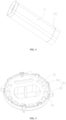
FIG. 1 is a perspective view of a heating structure according to an embodiment of the present invention. -
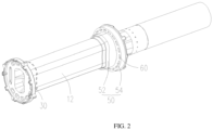
FIG. 2 is a perspective view of the heating structure shown inFIG. 1 viewed from another aspect. -
FIG. 3 is a cross-sectional view of the heating structure shown inFIG. 1 . -
FIG. 4 is a perspective view of a heating tube body shown inFIG. 1 . -
FIG. 5 is a perspective view of a base shown inFIG. 1 . -
FIG. 6 is a perspective view of a guiding member shown inFIG. 1 . - Description of reference numerals: 100, heating structure; 10, heating tube; 12, heating tube body; 30, base; 32, first portion; 34, second portion; 50, guiding member; 51, guiding hole; 52, guiding ring; 54, protruding ring; 60, heat insulation hole; 80, support protrusion; 82, first support protrusion; 84, second support protrusion; 86, third support protrusion.
- In order to make the above objects, features and advantages of the present invention more obvious and easier to understand, the specific embodiments of the present application are described in detail below in combination with the accompanying drawings. Many specific details are set forth in the following description to facilitate a full understanding of the invention. However, the present application can be implemented in many ways different from those described herein, and those skilled in the art can make similar improvements without violating the connotation of the invention. Therefore, the invention is not limited by the specific embodiments disclosed below. In the description of the present application, it should be understood that the terms "center", "longitudinal", "transverse", "length", "width", "thickness", "upper", "lower", "front", "rear", "left", "right", "vertical", "horizontal", "top", "bottom", "inner", "outer", "clockwise", "counterclockwise", "axial", "radial", "circumferential direction" are based on the azimuth or position relationship shown in the attached drawings, which is only for the convenience of describing the present application and simplifying the description, rather than indicating or implying that the device or element must have a specific azimuth, be constructed and operated in a specific azimuth, so it cannot be understood as a limitation of the present application.
- In addition, the terms "first" and "second" are only used for descriptive purposes and cannot be understood as indicating or implying relative importance or implicitly indicating the number of indicated technical features. Thus, the features defined with "first" and "second" may explicitly or implicitly include at least one of the features. In the description of the present application, "multiple" means at least two, such as two, three, etc., unless otherwise expressly and specifically defined.
- In the present invention, unless otherwise expressly specified and limited, the terms "mount", "connect", "contact", "fix" and other terms should be understood in a broad sense, for example, they can be fixed connections, removable connections, or integrated. It can be mechanical connection or electrical connection. It can be directly connected or indirectly connected through an intermediate medium. It can be the connection within two elements or the interaction relationship between two elements, unless otherwise expressly limited. For those skilled in the art, the specific meaning of the above terms in the present application can be understood according to the specific situation.
- In the present invention, unless otherwise expressly specified and limited, the first feature "above" or "below" the second feature may be in direct contact with the first and second features, or the first and second features may be in indirect contact through an intermediate medium. Moreover, the first feature is "above" the second feature, but the first feature is directly above or diagonally above the second feature, or it only means that the horizontal height of the first feature is higher than the second feature. The first feature is "below" of the second feature, which can mean that the first feature is directly below or obliquely below the second feature, or simply that the horizontal height of the first feature is less than that of the second feature.
- It should be noted that when an element is called "fixed to" or "provided on" another element, it can be directly on another element or there can be a centered element. When an element is considered to be "connected" to another element, it can be directly connected to another element or there may be intermediate elements at the same time. The terms "vertical", "horizontal", "up", "down", "left", "right" and similar expressions used herein are for the purpose of illustration only and do not represent the only embodiment.
- Referring to
FIG. 1 to FIG. 3 , aheating structure 100 is provided according to an embodiment of the present invention. Theheating structure 100 includes aheating tube 10 and abase 30. Theheating tube 10 is of a hollow structure having two openings at both axial ends thereof. Thebase 30 is fixed to one axial end of theheating tube 10 and covers the opening at the axial end of theheating tube 10, so that thebase 30 is fixed to the axial end of theheating tube 10. Thebase 30 and theheating tube 10 cooperatively form an accommodating cavity configured to accommodate an aerosol generating substrate. - When the
heating structure 100 is in use, theheating tube 10 generates heat to heat and atomize the aerosol generating substrate inside theheating tube 10. In an embodiment, theheating tube 10 is a resistance-type heating tube. For example, theheating tube 10 is provided with a resistance wire, and heat generated by the resistance wire is transferred to theheating tube 10, so that theheating tube 10 can transfer heat to the aerosol generating substrate. In another embodiment, theheating tube 10 generates heat through a principle of electromagnetic induction. For example, an electromagnetic induction coil is sleeved on theheating tube 10, so that theheating tube 10 can generate heat under an action of the electromagnetic induction coil. The manner in which theheating tube 10 generates heat is not limited hereto. - Further, at least one of the
heating tube 10 and thebase 30 is provided with aheat insulation hole 60, which can interrupt a heat transferring path from theheating tube 10 to an outside, thereby blocking or slowing down the heat transferred from theheating tube 10 to the outside. The heat is prevented from being transferred to the outside, which can reduce the heat loss of theheating tube 10, and reduce the energy consumption of the electronic atomization device to save power, and a standby time of the electronic atomization device is prolonged. - Further, a shape of the
heat insulation hole 60 is circular, square or racetrack, which is not limited herein. - In some embodiments, the
heating tube 10 includes aheating tube body 12 and a guidingmember 50. The guidingmember 50 is sleeved on the other axial end of theheating tube body 12, and is provided with a guiding hole 51 in communication with the interior of theheating tube body 12, so as to allow the aerosol generating substrate to be smoothly inserted into the accommodating cavity through the guiding hole 51. Optionally, the guidingmember 50 and theheating tube body 12 may be formed separately or integrally. The guidingmember 50 may be a guiding tube or other guiding structure, which is not limited herein. In some other embodiments, the guidingmember 50 can be omitted. - Referring to
FIG. 4 , in some embodiments, theheat insulation hole 60 is provided on theheating tube body 12, so as to interrupt a heat transferring path from theheating tube body 12 to the outside through theheat insulation hole 60, thereby blocking or slowing down the heat transferred from theheating tube body 12 to the outside. The heat is prevented from being transferred to the outside, which can reduce the energy consumption of the electronic atomization device, and the standby time of the electronic atomization device is prolonged. Further, a plurality of heat insulation holes 60 are spaced apart along the circumferential direction of theheating tube body 12, so as to block heat from all circumferential directions of theheating tube body 12 through the plurality of heat insulation holes 60, and the heat is uniformly blocked from being transferred to the outside along the circumferential direction of theheating tube body 12. Optionally, a distance between theheat insulation hole 60 and a bottom end of theheating tube body 12 is about 1mm to 10mm, and a width of a gap between adjacent two heat insulation holes 60 is about 0.4mm to 3mm. In some embodiment, the heat insulation holes 60 are through holes extending radially alongheating tube body 12. In an alternative embodiment, theheat insulation hole 60 may be a blind hole recessed radially along theheating tube body 12. A depth of theheat insulation hole 60 is not limited herein. - Referring to
FIGS. 1 to 3 andFIG. 5 , in some embodiments, theheat insulation hole 60 is provided on thebase 30, so as to interrupt the heat transferring path from theheating tube 10 to the outside through theheat insulation hole 60, thereby blocking or slowing down the heat transferred from theheating tube 10 to the outside. The heat is prevented from being transferred to the outside, which can reduce the energy consumption of the electronic atomization device, and the standby time of the electronic atomization device is prolonged. - Further, the
base 30 includes a first portion 32 and a second portion 34 surrounding the first portion 32. The first portion 32 covers the opening at one axial end of theheating tube body 12. The second portion 34 protrudes radially from theheating tube body 12, and theheat insulation hole 60 is provided on the second portion 34. In this way, the first portion 32 covers the opening at one end of theheating tube body 12, so that the first portion 32 and theheating tube body 12 cooperatively form the accommodating cavity configured to accommodate the aerosol generating substrate. Optionally, the first portion 32 is received in the opening at the axial end of theheating tube body 12, and the first portion 32 is fixed to theheating tube body 12 while covering the opening. - In addition, the second portion 34 is provided around a periphery of the first portion 32, and the
heat insulation hole 60 is provided on the second portion 34, so that other components, such as the electromagnetic induction coil, can be fixed an outer side of theheating tube body 12 through the second portion 34. Theheat insulation hole 60 provided on the second portion 34 can interrupt the heat transferring path from theheating tube 10 to the outside through thebase 30, so as to prevent the heat from diffusing to the outside. - Specifically, a plurality of heat insulation holes 60 spaced around the first portion 32 are provided on the second portion 34. The heat is blocked from all circumferential directions of the base 30 through the plurality of heat insulation holes 60, and the heat is uniformly blocked from being transferred to the outside in the circumferential direction of the
base 30. Optionally, a distance between theheat insulation hole 60 and an outer edge of the second portion 34 is about 0.5mm to 5mm, and the width of the gap between adjacent two heat insulation holes 60 is about 0.4mm to 3mm. In some embodiment, the heat insulation holes 60 are through holes extending through the base 30 in the axial direction. In an alternative embodiment, theheat insulation hole 60 may be a blind hole recessed radially along thebase 30. A depth of theheat insulation hole 60 is not limited herein. - Referring to
FIGS. 1 to 3 andFIG. 5 , in some embodiments, theheat insulation hole 60 is provided on the guidingmember 50, so as to interrupt the heat transferring path from theheating tube body 12 to the outside through theheat insulation hole 60, thereby blocking or slowing down the heat transferred from theheating tube body 12 to the outside. The heat is prevented from being transferred to the outside, which can reduce the energy consumption of the electronic atomization device, and the standby time of the electronic atomization device is prolonged. Further, the guidingmember 50 includes a guidingring 52 and a protrudingring 54. The guidingring 52 is sleeved on one axial end of theheating tube body 12 and is provided with a guiding hole 51. The protrudingring 54 surrounds the guidingring 52, and theheat insulation hole 60 is provided on the protrudingring 54. In this way, other components can be fixed an outer side theheating tube body 12 by the protrudingring 54, for example, the electromagnetic induction coil is fixed between the protrudingring 54 and the second portion 34. In addition, theheat insulation hole 60 provided on the protrudingring 54 can block the heat transferring path from theheating tube 10 to the outside through the guidingmember 50, so as to prevent the heat from diffusing to the outside. - Referring to
FIGS. 1 ,5 and6 , in some embodiments, at least one of the guidingmember 50 and thebase 30 is provided with asupport protrusion 80 protruding outward along the axial direction of theheating tube body 12 or along the radial direction of theheating tube body 12. Thesupport protrusion 80 is an outermost support point of theentire heating structure 100. When theheating structure 100 is mounted in a housing, theheating structure 100 is in point contact with the housing through thesupport protrusion 80. A contact area between theheating structure 100 and the housing is reduced, the heat transferring path from theheating tube 10 to the housing is further reduced, and the heat is further prevented from diffusing to the outside. - Referring to
FIGS. 1 and6 , thesupport protrusion 80 further includes afirst support protrusion 82 provided on the guidingmember 50. Thefirst support protrusion 82 protrudes from the guidingmember 50 in the direction away from thebase 30 along the axial direction of theheating tube body 12. In other words, thefirst support protrusion 82 is provided on a top of the guidingmember 50, so that the guidingmember 50 and the housing are in point contact with each other in the axial direction of theheating tube body 12 through thefirst support protrusion 82. A top of theheating structure 100 is thermally isolated in the axial direction of theheating tube body 12, thereby further preventing heat from being transferred axially to the housing along the top of theheating tube body 12, and the heat diffusion is reduced. - Referring to
FIG. 1 andFIG. 5 , further, thesupport protrusion 80 includes asecond support protrusion 84 provided on thebase 30. Thesecond support protrusion 84 protrudes from the base 30 in the direction away from the guidingmember 50 along the axial direction of theheating tube body 12. In other words, thesecond support protrusion 84 is provided at a bottom of thebase 30, so that thebase 30 and the housing are in point contact with each other in the axial direction of theheating tube body 12 through thesecond support protrusion 84. A bottom of theheating structure 100 is thermally isolated in the axial direction of theheating tube body 12, thereby further preventing heat from being transferred axially to the housing along the bottom of theheating tube body 12, and the heat diffusion is reduced. - Specifically, the
support protrusion 80 includes athird support protrusion 86 provided on thebase 30, thethird support protrusion 86 protrudes from the base 30 in the radial direction of theheating tube body 12. In other words, thethird support protrusion 86 is provided protruding from an outer peripheral surface of thebase 30, so that thebase 30 and the housing are in point contact with each other in the radial direction of theheating tube body 12 through thethird support protrusion 86. Theheating structure 100 is thermally isolated in the radial direction of theheating tube body 12, thereby further preventing heat from being transferred to the housing along the radial direction of theheating tube body 12, and the heat diffusion is reduced. - In this embodiment, the
support protrusions 80 include thefirst support protrusion 82, thesecond support protrusion 84, and thethird support protrusion 86. Thefirst support protrusion 82 and thesecond support protrusion 84 support theheating structure 100 at points at opposite ends of theheating tube body 12 in the axial direction, and thethird support protrusion 86 supports theheating structure 100 at points along the radial direction of theheating tube body 12, so that an upper end surface, a lower end surface, and an outer peripheral surface of theentire heating structure 100 are in point contact with the housing. A contact area between each outer peripheral surface of theheating structure 100 and the housing is reduced, which effectively blocks or slows down the transferring of heat to the housing. - In an embodiment of the present invention, an electronic atomizer is provided, which includes a housing and the
heating structure 100 in any one of the aforementioned embodiments. Theheating structure 100 is sleeved in the housing, so as to protect theheating structure 100 through the housing. Theheating structure 100 includes theheating tube 10 and thebase 30. Theheating tube 10 is configured as a hollow structure with the two openings at both axial ends. Thebase 30 is fixed to one axial end of theheating tube 10 and covers the opening at the axial end of theheating tube 10, so that thebase 30 is fixed on the axial end of theheating tube 10. Thebase 30 and theheating tube 10 cooperatively form the accommodating cavity configured to accommodate the aerosol generating substrate. - When the
heating structure 100 is in use, theheating tube 10 generates heat to heat and atomize the aerosol generating substrate inside theheating tube 10. In an embodiment, theheating tube 10 is a resistance-type heating tube. For example, theheating tube 10 is provided with a resistance wire, and heat generated by the resistance wire is transferred to theheating tube 10, so that theheating tube 10 transfers heat to the aerosol generating substrate. In another embodiment, theheating tube 10 generates heat through electromagnetic induction. For example, an electromagnetic induction coil is sleeved on theheating tube 10, so that theheating tube 10 generates heat under an action of the electromagnetic induction coil. The way in which theheating tube 10 generates heat is not limited herein. - At least one of the
heating tube 10 and thebase 30 is provided with aheat insulation hole 60, so as to interrupt a heat transferring path from theheating tube 10 to an outside through theheat insulation hole 60, thereby blocking or slowing down the heat transferred from theheating tube 10 to the outside. The heat is prevented from being transferred to the outside, which can reduce the heat loss of theheating tube 10, and reduce the energy consumption of the electronic atomization device to save power, and the standby time of the electronic atomization device is prolonged.
Claims (14)
- A heating structure (100), comprising:a heating tube (10) having two openings at both axial ends thereof; anda base (30) fixed to one axial end of the heating tube (10) and covering the opening at the axial end of the heating tube (10);wherein at least one of the heating tube (10) and the base (30) is provided with a heat insulation hole (60).
- The heating structure (100) according to claim 1, wherein the heating tube (10) comprises a heating tube body (12) and a guiding member (50), the guiding member (50) is sleeved on one axial end of the heating tube body (12) and is provided with a guiding hole (51) in communication with the interior of the heating tube body (12), wherein the heat insulation hole (60) is provided on at least one of the heating tube body (12), the guiding member (50), and the base (30).
- The heating structure (100) according to claim 2, wherein the heat insulation hole (60) is provided on the heating tube body (12).
- The heating structure (100) according to claim 3, wherein a plurality of heat insulation holes (60) are spaced apart along the circumferential direction of the heating tube body (12).
- The heating structure (100) according to claim 2, wherein the heat insulation hole (60) is provided on the base (30).
- The heating structure (100) according to claim 5, wherein the base (30) comprises a first portion (32) and a second portion (34) surrounding the first portion (32), the first portion (32) covers the opening at the axial end of the heating tube body (12), the second portion (34) protrudes radially from the heating tube body (12), and the heat insulation hole (60) is provided on the second portion (34).
- The heating structure (100) according to claim 6, wherein a plurality of heat insulation holes (60) spaced apart around the first portion (32) are provided on the second portion (34).
- The heating structure (100) according to claim 2, wherein the heat insulation hole (60) is provided on the guiding member (50).
- The heating structure (100) according to claim 8, wherein the guiding member (50) comprises a guiding ring (52) and a protruding ring (54), the guiding ring (52) is sleeved on one axial end of the heating tube body (12), the guiding hole (51) is provided on the guiding ring (52), the protruding ring (54) surrounds the guiding ring (52), and the heat insulation hole (60) is provided on the protruding ring (54).
- The heating structure (100) according to any one of claim 2 to claim 9, wherein at least one of the guiding member (50) and the base (30) is provided with a support protrusion (80), and the support protrusion (80) protrudes outward along the axial direction of the heating tube body (12) or along the radial direction of the heating tube body (12).
- The heating structure (100) according to claim 10, wherein the support protrusion (80) comprises a first support protrusion (82) provided on the guiding member (50), and the first support protrusion (82) protrudes from the guiding member (50) in the direction away from the base (30) along the axial direction of the heating tube body (12).
- The heating structure (100) according to claim 10, wherein the support protrusion (80) comprises a second support protrusion (84) provided on the base (30), and the second support protrusion (84) protrudes from the base (30) in the direction away from the guiding member (50) along the axial direction of the heating tube body (12).
- The heating structure (100) according to claim 10, wherein the support protrusion (80) comprises a third support protrusion (86) provided on the base (30), and the third support protrusion (86) protrudes from the base (30) along the radial direction of the heating tube body (12).
- An electronic atomization device, comprising a housing and the heating structure (100) according to any one of claims 1 to 13, wherein the heating structure (100) is received in the housing.
Applications Claiming Priority (1)
| Application Number | Priority Date | Filing Date | Title |
|---|---|---|---|
| CN202210923967.1A CN115191665A (en) | 2022-08-02 | 2022-08-02 | Heating structure and electronic atomization device |
Publications (1)
| Publication Number | Publication Date |
|---|---|
| EP4316278A1 true EP4316278A1 (en) | 2024-02-07 |
Family
ID=83585107
Family Applications (1)
| Application Number | Title | Priority Date | Filing Date |
|---|---|---|---|
| EP23186464.6A Pending EP4316278A1 (en) | 2022-08-02 | 2023-07-19 | Heating structure and electronic atomization device |
Country Status (4)
| Country | Link |
|---|---|
| EP (1) | EP4316278A1 (en) |
| JP (1) | JP7707240B2 (en) |
| KR (1) | KR102953859B1 (en) |
| CN (1) | CN115191665A (en) |
Families Citing this family (1)
| Publication number | Priority date | Publication date | Assignee | Title |
|---|---|---|---|---|
| CN120959466A (en) * | 2024-05-15 | 2025-11-18 | 深圳市合元科技有限公司 | Heating components and aerosol generating device |
Citations (5)
| Publication number | Priority date | Publication date | Assignee | Title |
|---|---|---|---|---|
| US20180303166A1 (en) * | 2016-06-08 | 2018-10-25 | Joyetech Europe Holding Gmbh | Atomizer and electronic cigarette having same |
| US20190142069A1 (en) * | 2016-07-03 | 2019-05-16 | Changzhou Jwei Intelligent Technology Co., Ltd. | Atomizing head, atomizer and electronic cigarette thereof |
| CN212545566U (en) * | 2020-07-20 | 2021-02-19 | 深圳麦克韦尔科技有限公司 | Heating element and aerosol generating device |
| CN214903779U (en) * | 2021-01-29 | 2021-11-30 | 惠州市新泓威科技有限公司 | Atomizer with atomizing core provided with sleeve |
| WO2022017162A1 (en) * | 2020-07-20 | 2022-01-27 | 深圳麦克韦尔科技有限公司 | Heating element and aerosol generating device |
Family Cites Families (12)
| Publication number | Priority date | Publication date | Assignee | Title |
|---|---|---|---|---|
| PL2797445T3 (en) * | 2011-12-30 | 2016-11-30 | Aerosol generating device with improved temperature distribution | |
| UA125080C2 (en) * | 2013-10-29 | 2022-01-05 | Брітіш Амерікан Тобакко (Інвестментс) Лімітед | Device for heating smoking material |
| CN105411004B (en) * | 2015-12-15 | 2018-03-13 | 深圳市赛尔美电子科技有限公司 | A new airflow preheating device |
| CN107536113B (en) * | 2017-09-05 | 2023-10-27 | 惠州市新泓威科技有限公司 | Heated non-combustible electronic cigarette |
| CN108308718A (en) * | 2018-03-30 | 2018-07-24 | 深圳达钿科技有限公司 | A kind of Novel U-shaped low temperature flue-cured tobacco |
| US20220287376A1 (en) * | 2019-08-23 | 2022-09-15 | Philip Morris Products S.A. | Temperature detection in peripherally heated aerosol-generating device |
| CN215347033U (en) * | 2020-12-04 | 2021-12-31 | 深圳市新宜康创新技术有限公司 | Heating device and electronic cigarette |
| CN215455423U (en) * | 2021-06-03 | 2022-01-11 | 深圳麦克韦尔科技有限公司 | Heating member and heating atomization device |
| CN216701625U (en) * | 2021-08-17 | 2022-06-10 | 深圳麦克韦尔科技有限公司 | Atomizing pipe and atomizer |
| CN113729287A (en) * | 2021-09-08 | 2021-12-03 | 深圳麦克韦尔科技有限公司 | Guide member, heating unit, and aerosol generating device |
| CN113729288A (en) * | 2021-09-08 | 2021-12-03 | 深圳麦克韦尔科技有限公司 | Heating assembly and aerosol generating device |
| CN218337730U (en) * | 2022-08-02 | 2023-01-20 | 深圳麦克韦尔科技有限公司 | Heating structure and electronic atomization device |
-
2022
- 2022-08-02 CN CN202210923967.1A patent/CN115191665A/en active Pending
-
2023
- 2023-07-19 EP EP23186464.6A patent/EP4316278A1/en active Pending
- 2023-07-20 JP JP2023118215A patent/JP7707240B2/en active Active
- 2023-08-01 KR KR1020230100375A patent/KR102953859B1/en active Active
Patent Citations (5)
| Publication number | Priority date | Publication date | Assignee | Title |
|---|---|---|---|---|
| US20180303166A1 (en) * | 2016-06-08 | 2018-10-25 | Joyetech Europe Holding Gmbh | Atomizer and electronic cigarette having same |
| US20190142069A1 (en) * | 2016-07-03 | 2019-05-16 | Changzhou Jwei Intelligent Technology Co., Ltd. | Atomizing head, atomizer and electronic cigarette thereof |
| CN212545566U (en) * | 2020-07-20 | 2021-02-19 | 深圳麦克韦尔科技有限公司 | Heating element and aerosol generating device |
| WO2022017162A1 (en) * | 2020-07-20 | 2022-01-27 | 深圳麦克韦尔科技有限公司 | Heating element and aerosol generating device |
| CN214903779U (en) * | 2021-01-29 | 2021-11-30 | 惠州市新泓威科技有限公司 | Atomizer with atomizing core provided with sleeve |
Also Published As
| Publication number | Publication date |
|---|---|
| KR102953859B1 (en) | 2026-04-17 |
| JP7707240B2 (en) | 2025-07-14 |
| JP2024021057A (en) | 2024-02-15 |
| CN115191665A (en) | 2022-10-18 |
| KR20240018387A (en) | 2024-02-13 |
Similar Documents
| Publication | Publication Date | Title |
|---|---|---|
| EP4285759A1 (en) | Heating unit, vaporization assembly, and electronic vaporizer | |
| US20240373924A1 (en) | Atomization core and atomization device using liquid storage cotton | |
| JP7719307B2 (en) | Atomizers and electronic atomizers | |
| US12588703B2 (en) | Electronic atomization device and atomizer thereof | |
| EP4194037B1 (en) | Atomizer and electronic atomizing device | |
| CN217487672U (en) | Electronic atomization device and atomizer and atomization core thereof | |
| EP4252560A1 (en) | Heater, and heating atomization apparatus | |
| KR102849143B1 (en) | Atomizer, sealing element and electronic atomization device | |
| EP4353096A1 (en) | Aerosol generating device | |
| JP7707240B2 (en) | Heat generating structure and electronic atomizing device | |
| CN218851939U (en) | Heating structure and electronic atomization device | |
| CN218337730U (en) | Heating structure and electronic atomization device | |
| JP7737558B2 (en) | Atomizer and electronic atomizer | |
| US20240237746A1 (en) | Electronic vaporization device and vaporizer thereof | |
| EP4223157B1 (en) | Atomizing core with air flow chamber | |
| KR102917824B1 (en) | Electronic atomization device | |
| CN217065416U (en) | Electronic atomization device and heating assembly and heating body thereof | |
| CN218635317U (en) | Electronic atomization device, atomizer and supporting structure | |
| CN218043796U (en) | Heating module, atomizing component and electronic atomizer | |
| CN114190604A (en) | Electronic atomization device and heating assembly and heating body thereof | |
| CN112074144B (en) | Support structure of electric heater and electric heater | |
| CN118058509A (en) | Aerosol Generating Device | |
| CN215687040U (en) | Lid assembly and have its cooking utensil | |
| CN223195549U (en) | Airflow guide, heating assembly and atomizing device | |
| RU2829477C1 (en) | Spraying core and spraying device using cotton element for liquid storage |
Legal Events
| Date | Code | Title | Description |
|---|---|---|---|
| PUAI | Public reference made under article 153(3) epc to a published international application that has entered the european phase |
Free format text: ORIGINAL CODE: 0009012 |
|
| STAA | Information on the status of an ep patent application or granted ep patent |
Free format text: STATUS: THE APPLICATION HAS BEEN PUBLISHED |
|
| AK | Designated contracting states |
Kind code of ref document: A1 Designated state(s): AL AT BE BG CH CY CZ DE DK EE ES FI FR GB GR HR HU IE IS IT LI LT LU LV MC ME MK MT NL NO PL PT RO RS SE SI SK SM TR |
|
| STAA | Information on the status of an ep patent application or granted ep patent |
Free format text: STATUS: REQUEST FOR EXAMINATION WAS MADE |
|
| 17P | Request for examination filed |
Effective date: 20240527 |
|
| RBV | Designated contracting states (corrected) |
Designated state(s): AL AT BE BG CH CY CZ DE DK EE ES FI FR GB GR HR HU IE IS IT LI LT LU LV MC ME MK MT NL NO PL PT RO RS SE SI SK SM TR |
|
| RAP3 | Party data changed (applicant data changed or rights of an application transferred) |
Owner name: SHENZHEN SMOORE TECHNOLOGY LIMITED |
|
| RAP3 | Party data changed (applicant data changed or rights of an application transferred) |
Owner name: SHENZHEN SMOORE TECHNOLOGY LIMITED |