EP4316226A1 - Hitching assembly - Google Patents
Hitching assembly Download PDFInfo
- Publication number
- EP4316226A1 EP4316226A1 EP23184833.4A EP23184833A EP4316226A1 EP 4316226 A1 EP4316226 A1 EP 4316226A1 EP 23184833 A EP23184833 A EP 23184833A EP 4316226 A1 EP4316226 A1 EP 4316226A1
- Authority
- EP
- European Patent Office
- Prior art keywords
- assembly
- point assembly
- support
- support member
- hitching
- Prior art date
- Legal status (The legal status is an assumption and is not a legal conclusion. Google has not performed a legal analysis and makes no representation as to the accuracy of the status listed.)
- Granted
Links
Images




Classifications
-
- A—HUMAN NECESSITIES
- A01—AGRICULTURE; FORESTRY; ANIMAL HUSBANDRY; HUNTING; TRAPPING; FISHING
- A01B—SOIL WORKING IN AGRICULTURE OR FORESTRY; PARTS, DETAILS, OR ACCESSORIES OF AGRICULTURAL MACHINES OR IMPLEMENTS, IN GENERAL
- A01B59/00—Devices specially adapted for connection between animals or tractors and agricultural machines or implements
- A01B59/002—Details, component parts
-
- A—HUMAN NECESSITIES
- A01—AGRICULTURE; FORESTRY; ANIMAL HUSBANDRY; HUNTING; TRAPPING; FISHING
- A01B—SOIL WORKING IN AGRICULTURE OR FORESTRY; PARTS, DETAILS, OR ACCESSORIES OF AGRICULTURAL MACHINES OR IMPLEMENTS, IN GENERAL
- A01B59/00—Devices specially adapted for connection between animals or tractors and agricultural machines or implements
- A01B59/04—Devices specially adapted for connection between animals or tractors and agricultural machines or implements for machines pulled or pushed by a tractor
- A01B59/042—Devices specially adapted for connection between animals or tractors and agricultural machines or implements for machines pulled or pushed by a tractor having pulling means arranged on the rear part of the tractor
- A01B59/043—Devices specially adapted for connection between animals or tractors and agricultural machines or implements for machines pulled or pushed by a tractor having pulling means arranged on the rear part of the tractor supported at three points, e.g. by quick-release couplings
-
- A—HUMAN NECESSITIES
- A01—AGRICULTURE; FORESTRY; ANIMAL HUSBANDRY; HUNTING; TRAPPING; FISHING
- A01B—SOIL WORKING IN AGRICULTURE OR FORESTRY; PARTS, DETAILS, OR ACCESSORIES OF AGRICULTURAL MACHINES OR IMPLEMENTS, IN GENERAL
- A01B59/00—Devices specially adapted for connection between animals or tractors and agricultural machines or implements
- A01B59/04—Devices specially adapted for connection between animals or tractors and agricultural machines or implements for machines pulled or pushed by a tractor
- A01B59/042—Devices specially adapted for connection between animals or tractors and agricultural machines or implements for machines pulled or pushed by a tractor having pulling means arranged on the rear part of the tractor
-
- A—HUMAN NECESSITIES
- A01—AGRICULTURE; FORESTRY; ANIMAL HUSBANDRY; HUNTING; TRAPPING; FISHING
- A01B—SOIL WORKING IN AGRICULTURE OR FORESTRY; PARTS, DETAILS, OR ACCESSORIES OF AGRICULTURAL MACHINES OR IMPLEMENTS, IN GENERAL
- A01B59/00—Devices specially adapted for connection between animals or tractors and agricultural machines or implements
- A01B59/06—Devices specially adapted for connection between animals or tractors and agricultural machines or implements for machines mounted on tractors
- A01B59/066—Devices specially adapted for connection between animals or tractors and agricultural machines or implements for machines mounted on tractors of the type comprising at least two lower arms and one upper arm generally arranged in a triangle, e.g. three-point hitches
-
- A—HUMAN NECESSITIES
- A01—AGRICULTURE; FORESTRY; ANIMAL HUSBANDRY; HUNTING; TRAPPING; FISHING
- A01B—SOIL WORKING IN AGRICULTURE OR FORESTRY; PARTS, DETAILS, OR ACCESSORIES OF AGRICULTURAL MACHINES OR IMPLEMENTS, IN GENERAL
- A01B63/00—Lifting or adjusting devices or arrangements for agricultural machines or implements
- A01B63/02—Lifting or adjusting devices or arrangements for agricultural machines or implements for implements mounted on tractors
-
- A—HUMAN NECESSITIES
- A01—AGRICULTURE; FORESTRY; ANIMAL HUSBANDRY; HUNTING; TRAPPING; FISHING
- A01B—SOIL WORKING IN AGRICULTURE OR FORESTRY; PARTS, DETAILS, OR ACCESSORIES OF AGRICULTURAL MACHINES OR IMPLEMENTS, IN GENERAL
- A01B73/00—Means or arrangements to facilitate transportation of agricultural machines or implements, e.g. folding frames to reduce overall width
- A01B73/02—Folding frames
- A01B73/04—Folding frames foldable about a horizontal axis
- A01B73/048—Folding frames foldable about a horizontal axis the axis being oriented in transverse direction
-
- A—HUMAN NECESSITIES
- A01—AGRICULTURE; FORESTRY; ANIMAL HUSBANDRY; HUNTING; TRAPPING; FISHING
- A01D—HARVESTING; MOWING
- A01D34/00—Mowers; Mowing apparatus of harvesters
- A01D34/01—Mowers; Mowing apparatus of harvesters characterised by features relating to the type of cutting apparatus
- A01D34/412—Mowers; Mowing apparatus of harvesters characterised by features relating to the type of cutting apparatus having rotating cutters
- A01D34/63—Mowers; Mowing apparatus of harvesters characterised by features relating to the type of cutting apparatus having rotating cutters having cutters rotating about a vertical axis
- A01D34/64—Mowers; Mowing apparatus of harvesters characterised by features relating to the type of cutting apparatus having rotating cutters having cutters rotating about a vertical axis mounted on a vehicle, e.g. a tractor, or drawn by an animal or a vehicle
- A01D34/66—Mowers; Mowing apparatus of harvesters characterised by features relating to the type of cutting apparatus having rotating cutters having cutters rotating about a vertical axis mounted on a vehicle, e.g. a tractor, or drawn by an animal or a vehicle with two or more cutters
- A01D34/661—Mounting means
-
- B—PERFORMING OPERATIONS; TRANSPORTING
- B60—VEHICLES IN GENERAL
- B60D—VEHICLE CONNECTIONS
- B60D1/00—Traction couplings; Hitches; Draw-gear; Towing devices
- B60D1/01—Traction couplings or hitches characterised by their type
- B60D1/06—Ball-and-socket hitches
-
- B—PERFORMING OPERATIONS; TRANSPORTING
- B60—VEHICLES IN GENERAL
- B60D—VEHICLE CONNECTIONS
- B60D1/00—Traction couplings; Hitches; Draw-gear; Towing devices
- B60D1/24—Traction couplings; Hitches; Draw-gear; Towing devices characterised by arrangements for particular functions
- B60D1/36—Traction couplings; Hitches; Draw-gear; Towing devices characterised by arrangements for particular functions for facilitating connection, e.g. hitch catchers
- B60D1/363—Hitch guiding or catching elements, e.g. V-shaped plates partially surrounding a coupling member for guiding the other coupling member
-
- B—PERFORMING OPERATIONS; TRANSPORTING
- B60—VEHICLES IN GENERAL
- B60D—VEHICLE CONNECTIONS
- B60D1/00—Traction couplings; Hitches; Draw-gear; Towing devices
- B60D1/48—Traction couplings; Hitches; Draw-gear; Towing devices characterised by the mounting
- B60D1/481—Traction couplings; Hitches; Draw-gear; Towing devices characterised by the mounting adapted for being mounted to the front and back of trailers, carts, trolleys or the like to form a train
-
- B—PERFORMING OPERATIONS; TRANSPORTING
- B60—VEHICLES IN GENERAL
- B60D—VEHICLE CONNECTIONS
- B60D1/00—Traction couplings; Hitches; Draw-gear; Towing devices
- B60D1/48—Traction couplings; Hitches; Draw-gear; Towing devices characterised by the mounting
- B60D1/485—Traction couplings; Hitches; Draw-gear; Towing devices characterised by the mounting mounted by means of transversal members attached to the frame of a vehicle
-
- B—PERFORMING OPERATIONS; TRANSPORTING
- B60—VEHICLES IN GENERAL
- B60D—VEHICLE CONNECTIONS
- B60D1/00—Traction couplings; Hitches; Draw-gear; Towing devices
- B60D1/48—Traction couplings; Hitches; Draw-gear; Towing devices characterised by the mounting
- B60D1/488—Traction couplings; Hitches; Draw-gear; Towing devices characterised by the mounting mounted directly to the chassis of the towing vehicle
-
- B—PERFORMING OPERATIONS; TRANSPORTING
- B60—VEHICLES IN GENERAL
- B60D—VEHICLE CONNECTIONS
- B60D1/00—Traction couplings; Hitches; Draw-gear; Towing devices
- B60D1/48—Traction couplings; Hitches; Draw-gear; Towing devices characterised by the mounting
- B60D1/52—Traction couplings; Hitches; Draw-gear; Towing devices characterised by the mounting removably mounted
Definitions
- a tractor or utility vehicle used for agricultural work may be used for transport tasks and for carrying out tasks in the field.
- the tractor or utility vehicle can be coupled to an implement that has electoral couplers, hydraulic couplers, and/or a power takeoff that is connected to the tractor couplers and to the tractor power takeoff.
- Implements attached to a tractor or utility vehicle are generally not utilized full time, and thus a coupling mechanism is provided to allow for convenient connecting and disconnecting of the implement.
- a hitching assembly for coupling to a hitch assembly on a vehicle.
- the hitching assembly includes a single point assembly including a first attachment area for attaching to the hitch assembly and a support passage extending through the single point assembly, and a two-point assembly extending through the support passage, the two-point assembly having second and third attachment areas for attaching to the hitch assembly.
- the two-point assembly is movable from a raised position where the two-point assembly is coupled to the single point assembly to form a rigid assembly, to a lowered position where the two-point assembly is decoupled from the single point assembly to move relative to the single point assembly among a plurality of degrees of freedom for adjusting a position of the two-point assembly relative to the hitch assembly.
- a hitching assembly for coupling to a hitch assembly on a vehicle.
- the hitching assembly includes a single point assembly including a body portion having a first attachment area for attaching to the hitch assembly, and a support portion having a support passage extending therethrough, a two-point assembly including a support member extending through the support passage, one or more first arms attached to a first side of the support member that have a second attachment area for attaching to the hitch assembly, and one or more second arms attached to a second side of the support member that have a third attachment area for attaching to the hitch assembly, and one or more manually-operated latch mechanisms configured to couple the two-point assembly to the single point assembly.
- the two-point assembly is movable from a raised position where the two-point assembly is coupled to the single point assembly by the one or more manually-operated latch mechanisms to form a rigid assembly, to a lowered position where the two-point assembly is decoupled from the single point assembly to move relative to the single point assembly while being constrained by the support passage.
- an implement having a functional portion, a lifting assembly attached to the functional portion, and a hitching assembly.
- the hitching assembly includes a single point assembly including a rear portion coupled to the lifting assembly, a body portion coupled to the rear portion having a first attachment area for attaching to a hitch assembly of a vehicle, and a support portion having a support passage extending therethrough, and a two-point assembly including a support member extending through and being constrained by the support passage, one or more first arms extending from the support member having a second attachment area for attaching to the hitch assembly, and one or more second arms extending from the support member having a third attachment area for attaching to the hitch assembly.
- the two-point assembly is movable from a raised position coupled to the single point assembly to a lowered position decoupled from and movable relative to the single point assembly.
- a vehicle such as a utility vehicle or tractor
- the vehicle 10 includes a frame 12, front tires 14, rear tires 16, a vehicle cab 18, an engine 20, and a hitch assembly 22 having a suitable design, such as a three point hitch having pair of lower arms 24 and an upper arm 26.
- the engine 20 may be any suitable engine, such as a diesel engine, or alternatively may be replaced by a suitable electric motor assembly.
- an exemplary implement 30, such as a mower implement, is shown that can be attached to the hitch assembly 22.
- the implement includes a functional portion, such as a mower bar 32, a lifting assembly 34 attached to the mower bar 32, and a hitching assembly 36 attached to the lifting assembly 34.
- the hitching assembly 36 can include a first or single point assembly 38 and a second or two-point assembly 40 that can be coupled together by one or more manually-operated latch mechanisms 42, such as pins, spring-loaded latches, etc. in a raised position as shown in FIG. 3 .
- the two-point assembly 40 can be decoupled but remain constrained by the single point assembly 38 and can be moved independently of the single point assembly 38.
- the two-point assembly 40 may be moved to a lowered position as shown in FIGs. 4-6 , moved at various angles in up and down directions relative to the single point assembly 38 as shown in FIG. 7 , and moved at various angles in front to back directions relative to the single point assembly 38 as shown in FIG. 8 .
- the single point assembly 38 includes a rear portion 48, which is shown as tubular in shape but may have any suitable shape, for attaching to the lifting assembly 34 in a suitable manner, a body portion 50 for attaching to the upper arm 26, and a support portion 52 for constraining and coupling to the two-point assembly 40.
- the rear portion 48 may be coupled to the body portion 50 in a suitable manner, such as by welding, although it will be appreciated that the components may be integrally formed.
- the body portion 50 may include a base 54 coupled to the rear portion 48 that has a suitable shape, such as a substantially rectangular tubular shape, and a pair of laterally spaced projections 56 extending forward of the base 54.
- the base 54 includes openings 58 on each side thereof that are aligned with one another for receiving the support portion 52.
- the laterally spaced projections 56 form an attachment area for coupling to the upper arm 26.
- the laterally spaced projections 56 may each having one or more openings 60, and as shown a plurality of openings 60 aligned with a corresponding opening 60 on the other laterally spaced projection 56.
- the plurality of openings 60 can receive a suitable pin(s) or other mechanism for interacting with the upper arm 26.
- the support portion 52 extends through the openings 58 of the base 54 of the body portion 50, for example substantially perpendicular to the base 54, and may be coupled thereto in a suitable manner, such as by a weld 62, although it will be appreciated that the components may be integrally formed.
- the support portion 52 has a support passage 64 extending therethrough, a first opening 66 extending through a front face 68 into the support passage 64, and a second opening 70 extending through a rear face 72 into the support passage 64.
- the first and second openings 66 and 70 extend substantially perpendicular to the support passage 64.
- the first and second openings 66 and 70 may be aligned with one another and each have a suitable geometry that converges towards a top of the respective opening 66, 70 and that allows for movement of the two-point assembly 40 relative to the single point assembly 38 and also serves to center the two-point assembly 40 relative to the single point assembly 38.
- the first and second openings 66 and 70 may each have a substantially triangular shape with rounded corners, such as an equilateral triangular shape, where the rounded corners can be curved to correspond to a diameter of a latch mechanism 74, such as a pin 74 to allow for seating of the pin 74 in the corners.
- the pin 74 is movable about the openings 66 and 70 to constrain movement of the two-point assembly.
- the front face 68 of the support portion 52 has a pair of opposed ears 80 protruding away from the sides of the base 54 past the openings 58, where each ear 80 has an opening 82 for receiving one of the manually-operated latch mechanisms 42.
- the rear face 72 has a pair of opposed ears 84 protruding away from the sides of the base 54 past the openings 58, where each ear 84 has an opening 86 for receiving one of the manually-operated latch mechanisms 42.
- the openings 82 and 86 on the left side of the support portion 52 are aligned with one another and the openings 82 and 86 on the right side of the support portion 52 are aligned with one another for receiving the manually-operated latch mechanisms 42.
- the support passage 64 is substantially trapezoidal in shape with rounded corners, such as an equilateral trapezoidal shape, where the top and bottom of the support passage 64 are substantially parallel to one another and the sides of the support passage 64 converge or angle toward the top of the support passage 64 such that the passage is narrower at its top than at its bottom.
- This configuration allows for the two-point assembly 40 to be locked relative to the single point assembly 38 when the two-point assembly is in the raised position at the top of the support passage 64, and allows for the two-point assembly 40 to be moved front to back within the support passage 64 when decoupled in the lowered position.
- the two-point assembly 40 includes a support member 90 configured to extend through the support passage 64, a pair of outer arms 92 coupled to opposite ends of the support member 90, a pair of inner arms 94 laterally spaced from a respective one of the outer arms 92 and coupled to the support member 90, and a pair of reinforcement plates 96 coupled to a respective pair of the outer and inner arms 92 and 94 and the support member 90.
- the outer and inner arms 92 and 94 each form an attachment area for coupling to the lower arms 24.
- each outer arm 92 may include an opening 98 and each inner arm 94 may include an opening 100 that is aligned with the respective opening 98 to receive a pin or the like for interacting with the respective lower arm 24.
- the support member 90 has a profile substantially similar to the profile of the support passage 64. As shown, the support member 90 includes front and back non-parallel sides 102 and 104 that converge or angle toward a top wall 106 such that the support member 90 is narrower at its top than at its bottom.
- the support member 90 is shown without a bottom wall, although it will be appreciated that a bottom wall can be included to form a substantially trapezoidal shape similar to the support passage 64.
- the support member 90 also includes a pair of laterally spaced openings 108 on the front side 102 aligned with a respective one of a pair of laterally spaced openings 110 on the back side 104 for receiving a respect one of the manually-operated latch mechanisms 42, and a central opening 112 on the front side 102 aligned with a central opening 114 on the back side 104.
- the central openings 112 and 114 are configured to receive a tubular member 116, which may be attached to the support member 90 at the central openings 112 and 114 in a suitable manner, such as by welding, or may be integrally formed therewith.
- the outer arms 92, inner arms 94, and reinforcement plates 96 may be coupled to the support member 90. It will be appreciated, however, that one side of the support member 90 may be coupled to one of the outer arms 92, one of the inner arms 94, and one of the reinforcement plates 96 prior to insertion through the support passage 64, and then after insertion the other side of the support member 90 may be coupled to the other of the outer arms 92, inner arms 94, and reinforcement plates 96.
- the pin 74 is also inserted through the first opening 66, through the tubular member 116, and through the second opening 70 after the support member 90 has been inserted through the support passage 64.
- the pin 74 may be coupled to the tubular member 116 in a suitable manner, such as by welding, or may be configured to be removably coupled to the tubular member 116.
- the pin 74 and the support passage 64 will serve to constrain motion of the support member 90 relative to the support portion 52, while the geometry of the support member 90 and the support passage 64 will allow for movement of the support member 90 in any direction in all degrees of freedom.
- hitching assembly 36 operation of hitching assembly 36 will be described in detail.
- the openings 82 and 86 in the support portion 52 of the single point assembly 38 are aligned with the openings 108 and 110 in the support member 90 of the two-point assembly 40, and the manually-operated latch mechanisms 42 are inserted through the openings 82, 86, 108, and 110, the single point assembly 38 and two-point assembly 40 will be locked together forming a rigid three-point assembly as shown in FIG. 2 .
- the three-point assembly can then be connected to the vehicle 10, for example to the pair of lower arms 24 and the upper arm 26.
- the top wall 106 of the support member 90 When in this raised position, the top wall 106 of the support member 90 is proximate to or abutting the top of the support passage 64, the front side 102 and back side 104 are proximate to or abutting the sides of the support passage 64, and movement of the support member 90 is restricted by the support passage 64.
- the two-point assembly 40 can be decoupled from the single point assembly 38 to facilitate this connection to the vehicle 10.
- the manually-operated latch mechanisms 42 are removed, and the two-point assembly 40 will move downward to a bottom of the support portion 52 as shown in FIGs. 4-6 to move relative to the single point assembly 38 while remaining constrained by the support portion 52.
- the user can then move the two-point assembly 40 relative to the vehicle 10 to align the pins or the like extending through the openings 98 and 100 in the outer and inner arms 92 and 94 with the lower arms 24.
- a gap is formed between the sides of the support passage 64 and the front side 102 and back side 104 of the support member 90 to allow the position of the two-point assembly 40 to be adjusted.
- the two-point assembly 40 may be angled such that the outer and inner arms 92 and 94 on the left side of the two-point assembly 40 are near a bottom of the support passage 64 and the outer and inner arms 92 and 94 on the right side of the two-point assembly 40 are near a top of the support passage 64 to allow for connection to a vehicle 10 at a first angle relative to the implement 30.
- the two-point assembly 40 may be angled such that the outer and inner arms 92 and 94 on the right side of the two-point assembly 40 are near the bottom of the support passage 64 and the outer and inner arms 92 and 94 on the left side of the two-point assembly 40 are near the top of the support passage 64 to allow for connection to a vehicle 10 at a second angle relative to the implement 30. It will be appreciated that the two-point assembly 40 may be moved upward and downward to any suitable angle within the support passage 64 to accommodate for various angular offsets of the vehicle 10.
- the two-point assembly 40 may be moved such that the outer and inner arms 92 and 94 on the left side of the two-point assembly 40 are moved forward toward a front of the support passage 64 and the outer and inner arms 92 and 94 on the right side of the two-point assembly 40 are moved backward toward a rear of the support passage 64 to allow for connection to a vehicle 10 at a third angle relative to the implement 30.
- the two-point assembly 40 may be moved such that the outer and inner arms 92 and 94 on the left side of the two-point assembly 40 are moved backward toward the rear of the support passage 64 and the outer and inner arms 92 and 94 on the right side of the two-point assembly 40 are moved forward toward the front of the support passage 64 to allow for connection to a vehicle 10 at a fourth angle relative to the implement 30. It will be appreciated that the two-point assembly 40 may be moved forward and backward to any suitable angle within the support passage 64 to accommodate for various angular offsets of the vehicle 10. It will also be appreciated that the two-point assembly may be moved upward, downward, forward, and backward in any suitable configuration to allow for alignment of the two-point assembly 40 to the vehicle 10 in all degrees of freedom.
- the lower arms 24 of the hitch assembly 22 are raised, thereby raising the two-point assembly 40 relative to the single point assembly 38.
- the gap between the front and back sides 102 and 104 of the support member 90 and the support passage 64 reduces due to the narrowing of the support passage 64 to locate the two-point assembly 40 and prevent front to back movement of the two-point assembly 40 relative to the single point assembly 46.
- the pin 74 will also be raised and converge to the top of the openings 66 and 70 to center the support member 90 relative to the single point assembly 38.
- the manually-operated latch mechanisms 42 are inserted through the openings 82 and 86 in the support portion 52 and the openings 108 and 110 in the support member 90 to lock the single point assembly 38 and two-point assembly 40 together forming the rigid three-point assembly. It will be appreciated that the pin or the like extending through openings 60 in the laterally spaced projections 56 will be aligned with the upper arm 26 when the two-point assembly 40 is in the raised position.
- exemplary is used herein to mean serving as an example, instance or illustration. Any aspect or design described herein as “exemplary” is not necessarily to be construed as advantageous over other aspects or designs. Rather, use of the word exemplary is intended to present concepts in a concrete fashion.
- the term “or” is intended to mean an inclusive “or” rather than an exclusive “or.” That is, unless specified otherwise, or clear from context, "X employs A or B” is intended to mean any of the natural inclusive permutations. That is, if X employs A; X employs B; or X employs both A and B, then "X employs A or B" is satisfied under any of the foregoing instances.
- At least one of A and B and/or the like generally means A or B or both A and B.
- the articles “a” and “an” as used in this application and the appended claims may generally be construed to mean “one or more” unless specified otherwise or clear from context to be directed to a singular form.
Landscapes
- Life Sciences & Earth Sciences (AREA)
- Engineering & Computer Science (AREA)
- Mechanical Engineering (AREA)
- Environmental Sciences (AREA)
- Soil Sciences (AREA)
- Transportation (AREA)
- Zoology (AREA)
- Agricultural Machines (AREA)
- Harvester Elements (AREA)
Abstract
Description
- A tractor or utility vehicle used for agricultural work may be used for transport tasks and for carrying out tasks in the field. The tractor or utility vehicle can be coupled to an implement that has electoral couplers, hydraulic couplers, and/or a power takeoff that is connected to the tractor couplers and to the tractor power takeoff. Implements attached to a tractor or utility vehicle are generally not utilized full time, and thus a coupling mechanism is provided to allow for convenient connecting and disconnecting of the implement.
- This Summary is provided to introduce a selection of concepts in a simplified form that are further described below in the Detailed Description. This Summary is not intended to identify key factors or essential features of the claimed subject matter, nor is it intended to be used to limit the scope of the claimed subject matter.
- In one implementation, a hitching assembly for coupling to a hitch assembly on a vehicle is provided. The hitching assembly includes a single point assembly including a first attachment area for attaching to the hitch assembly and a support passage extending through the single point assembly, and a two-point assembly extending through the support passage, the two-point assembly having second and third attachment areas for attaching to the hitch assembly. The two-point assembly is movable from a raised position where the two-point assembly is coupled to the single point assembly to form a rigid assembly, to a lowered position where the two-point assembly is decoupled from the single point assembly to move relative to the single point assembly among a plurality of degrees of freedom for adjusting a position of the two-point assembly relative to the hitch assembly.
- In another implementation, a hitching assembly for coupling to a hitch assembly on a vehicle is provided. The hitching assembly includes a single point assembly including a body portion having a first attachment area for attaching to the hitch assembly, and a support portion having a support passage extending therethrough, a two-point assembly including a support member extending through the support passage, one or more first arms attached to a first side of the support member that have a second attachment area for attaching to the hitch assembly, and one or more second arms attached to a second side of the support member that have a third attachment area for attaching to the hitch assembly, and one or more manually-operated latch mechanisms configured to couple the two-point assembly to the single point assembly. The two-point assembly is movable from a raised position where the two-point assembly is coupled to the single point assembly by the one or more manually-operated latch mechanisms to form a rigid assembly, to a lowered position where the two-point assembly is decoupled from the single point assembly to move relative to the single point assembly while being constrained by the support passage.
- In still another implementation, an implement is provided having a functional portion, a lifting assembly attached to the functional portion, and a hitching assembly. The hitching assembly includes a single point assembly including a rear portion coupled to the lifting assembly, a body portion coupled to the rear portion having a first attachment area for attaching to a hitch assembly of a vehicle, and a support portion having a support passage extending therethrough, and a two-point assembly including a support member extending through and being constrained by the support passage, one or more first arms extending from the support member having a second attachment area for attaching to the hitch assembly, and one or more second arms extending from the support member having a third attachment area for attaching to the hitch assembly. The two-point assembly is movable from a raised position coupled to the single point assembly to a lowered position decoupled from and movable relative to the single point assembly.
- To the accomplishment of the foregoing and related ends, the following description and annexed drawings set forth certain illustrative aspects and implementations. These are indicative of but a few of the various ways in which one or more aspects may be employed. Other aspects, advantages and novel features of the disclosure will become apparent from the following detailed description when considered in conjunction with the annexed drawings.
- What is disclosed herein may take physical form in certain parts and arrangement of parts, and will be described in detail in this specification and illustrated in the accompanying drawings which form a part hereof and wherein:
-
FIG. 1 is a side view of a tractor. -
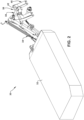
FIG. 2 is a perspective view of an exemplary implement. -
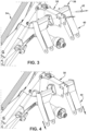
FIG. 3 is a partial perspective view of the implement illustrating a hitching assembly in a raised position. -
FIG. 4 is a partial perspective view of the implement illustrating the hitching assembly in a lowered position. -
FIG. 5 is a front view of the hitching assembly in the lowered position. -
FIG. 6 is a cross-sectional view of the hitching assembly in the lowered position. -
FIG. 7 is a front view of the hitching assembly illustrating angled movement of a two-point assembly relative to a single point assembly. -
FIG. 8 is a top view of the hitching assembly illustrating forward and backward movement of the two-point assembly relative to the single point assembly. -
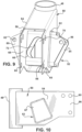
FIG. 9 is a perspective view of the single point assembly. -
FIG. 10 is a side view of the single point assembly. -
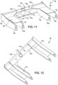
FIG. 11 is a perspective view of the two-point assembly. -
FIG. 12 is another perspective view of the two-point assembly. -
FIG. 13 is a partial front view of the hitching assembly in the raised position. -
FIG. 14 is a partial cross-sectional view of the hitching assembly in the raised position. - The claimed subject matter is now described with reference to the drawings, wherein like reference numerals are generally used to refer to like elements throughout. In the following description, for purposes of explanation, numerous specific details are set forth in order to provide a thorough understanding of the claimed subject matter. It may be evident, however, that the claimed subject matter may be practiced without these specific details. In other instances, structures and devices are shown in block diagram form in order to facilitate describing the claimed subject matter.
- Referring initially to
FIG. 1 , a vehicle, such as a utility vehicle or tractor, is shown atreference numeral 10. Thevehicle 10 includes aframe 12,front tires 14,rear tires 16, avehicle cab 18, anengine 20, and ahitch assembly 22 having a suitable design, such as a three point hitch having pair oflower arms 24 and anupper arm 26. Theengine 20 may be any suitable engine, such as a diesel engine, or alternatively may be replaced by a suitable electric motor assembly. - Turning now to
FIG. 2 , an exemplary implement 30, such as a mower implement, is shown that can be attached to thehitch assembly 22. The implement includes a functional portion, such as amower bar 32, a liftingassembly 34 attached to themower bar 32, and a hitchingassembly 36 attached to the liftingassembly 34. The hitchingassembly 36 can include a first orsingle point assembly 38 and a second or two-point assembly 40 that can be coupled together by one or more manually-operatedlatch mechanisms 42, such as pins, spring-loaded latches, etc. in a raised position as shown inFIG. 3 . The two-point assembly 40 can be decoupled but remain constrained by thesingle point assembly 38 and can be moved independently of thesingle point assembly 38. For example, the two-point assembly 40 may be moved to a lowered position as shown inFIGs. 4-6 , moved at various angles in up and down directions relative to thesingle point assembly 38 as shown inFIG. 7 , and moved at various angles in front to back directions relative to thesingle point assembly 38 as shown inFIG. 8 . - Turning additionally to
FIGs. 9 and 10 , thesingle point assembly 38 will be described in detail. Thesingle point assembly 38 includes arear portion 48, which is shown as tubular in shape but may have any suitable shape, for attaching to the liftingassembly 34 in a suitable manner, abody portion 50 for attaching to theupper arm 26, and asupport portion 52 for constraining and coupling to the two-point assembly 40. Therear portion 48 may be coupled to thebody portion 50 in a suitable manner, such as by welding, although it will be appreciated that the components may be integrally formed. Thebody portion 50 may include a base 54 coupled to therear portion 48 that has a suitable shape, such as a substantially rectangular tubular shape, and a pair of laterally spacedprojections 56 extending forward of thebase 54. Thebase 54 includesopenings 58 on each side thereof that are aligned with one another for receiving thesupport portion 52. The laterally spacedprojections 56 form an attachment area for coupling to theupper arm 26. For example, the laterally spacedprojections 56 may each having one ormore openings 60, and as shown a plurality ofopenings 60 aligned with acorresponding opening 60 on the other laterally spacedprojection 56. The plurality ofopenings 60 can receive a suitable pin(s) or other mechanism for interacting with theupper arm 26. - The
support portion 52 extends through theopenings 58 of thebase 54 of thebody portion 50, for example substantially perpendicular to thebase 54, and may be coupled thereto in a suitable manner, such as by aweld 62, although it will be appreciated that the components may be integrally formed. Thesupport portion 52 has asupport passage 64 extending therethrough, afirst opening 66 extending through afront face 68 into thesupport passage 64, and asecond opening 70 extending through arear face 72 into thesupport passage 64. In an embodiment, the first andsecond openings support passage 64. The first andsecond openings respective opening point assembly 40 relative to thesingle point assembly 38 and also serves to center the two-point assembly 40 relative to thesingle point assembly 38. For example, the first andsecond openings latch mechanism 74, such as apin 74 to allow for seating of thepin 74 in the corners. Thepin 74 is movable about theopenings - The
front face 68 of thesupport portion 52 has a pair ofopposed ears 80 protruding away from the sides of thebase 54 past theopenings 58, where eachear 80 has an opening 82 for receiving one of the manually-operatedlatch mechanisms 42. Similarly, therear face 72 has a pair ofopposed ears 84 protruding away from the sides of thebase 54 past theopenings 58, where eachear 84 has an opening 86 for receiving one of the manually-operatedlatch mechanisms 42. Theopenings support portion 52 are aligned with one another and theopenings support portion 52 are aligned with one another for receiving the manually-operatedlatch mechanisms 42. - As best shown in
FIG. 6 , thesupport passage 64 is substantially trapezoidal in shape with rounded corners, such as an equilateral trapezoidal shape, where the top and bottom of thesupport passage 64 are substantially parallel to one another and the sides of thesupport passage 64 converge or angle toward the top of thesupport passage 64 such that the passage is narrower at its top than at its bottom. This configuration allows for the two-point assembly 40 to be locked relative to thesingle point assembly 38 when the two-point assembly is in the raised position at the top of thesupport passage 64, and allows for the two-point assembly 40 to be moved front to back within thesupport passage 64 when decoupled in the lowered position. - Turning additionally to
FIGs. 11 and 12 , the two-point assembly 40 will be described in detail. The two-point assembly 40 includes asupport member 90 configured to extend through thesupport passage 64, a pair ofouter arms 92 coupled to opposite ends of thesupport member 90, a pair ofinner arms 94 laterally spaced from a respective one of theouter arms 92 and coupled to thesupport member 90, and a pair ofreinforcement plates 96 coupled to a respective pair of the outer andinner arms support member 90. The outer andinner arms lower arms 24. For example, eachouter arm 92 may include anopening 98 and eachinner arm 94 may include anopening 100 that is aligned with therespective opening 98 to receive a pin or the like for interacting with the respectivelower arm 24. - The
support member 90 has a profile substantially similar to the profile of thesupport passage 64. As shown, thesupport member 90 includes front and backnon-parallel sides top wall 106 such that thesupport member 90 is narrower at its top than at its bottom. Thesupport member 90 is shown without a bottom wall, although it will be appreciated that a bottom wall can be included to form a substantially trapezoidal shape similar to thesupport passage 64. Thesupport member 90 also includes a pair of laterally spacedopenings 108 on thefront side 102 aligned with a respective one of a pair of laterally spacedopenings 110 on theback side 104 for receiving a respect one of the manually-operatedlatch mechanisms 42, and acentral opening 112 on thefront side 102 aligned with acentral opening 114 on theback side 104. Thecentral openings tubular member 116, which may be attached to thesupport member 90 at thecentral openings - After the
support member 90 has been inserted through thesupport passage 64, theouter arms 92,inner arms 94, andreinforcement plates 96 may be coupled to thesupport member 90. It will be appreciated, however, that one side of thesupport member 90 may be coupled to one of theouter arms 92, one of theinner arms 94, and one of thereinforcement plates 96 prior to insertion through thesupport passage 64, and then after insertion the other side of thesupport member 90 may be coupled to the other of theouter arms 92,inner arms 94, andreinforcement plates 96. Thepin 74 is also inserted through thefirst opening 66, through thetubular member 116, and through thesecond opening 70 after thesupport member 90 has been inserted through thesupport passage 64. Once inserted, thepin 74 may be coupled to thetubular member 116 in a suitable manner, such as by welding, or may be configured to be removably coupled to thetubular member 116. Once thepin 74 is coupled to thetubular member 116, thepin 74 and thesupport passage 64 will serve to constrain motion of thesupport member 90 relative to thesupport portion 52, while the geometry of thesupport member 90 and thesupport passage 64 will allow for movement of thesupport member 90 in any direction in all degrees of freedom. - Turning now to
FIGs. 13 and 14 in addition toFIGs. 2-4 , and6-8 , operation of hitchingassembly 36 will be described in detail. When theopenings support portion 52 of thesingle point assembly 38 are aligned with theopenings support member 90 of the two-point assembly 40, and the manually-operatedlatch mechanisms 42 are inserted through theopenings single point assembly 38 and two-point assembly 40 will be locked together forming a rigid three-point assembly as shown inFIG. 2 . The three-point assembly can then be connected to thevehicle 10, for example to the pair oflower arms 24 and theupper arm 26. When in this raised position, thetop wall 106 of thesupport member 90 is proximate to or abutting the top of thesupport passage 64, thefront side 102 and backside 104 are proximate to or abutting the sides of thesupport passage 64, and movement of thesupport member 90 is restricted by thesupport passage 64. - In some instances, for example when a user desires to connect the
vehicle 10 to the implement 30 on uneven terrain, the two-point assembly 40 can be decoupled from thesingle point assembly 38 to facilitate this connection to thevehicle 10. To decouple thesingle point assembly 38 and the two-point assembly 40, the manually-operatedlatch mechanisms 42 are removed, and the two-point assembly 40 will move downward to a bottom of thesupport portion 52 as shown inFIGs. 4-6 to move relative to thesingle point assembly 38 while remaining constrained by thesupport portion 52. The user can then move the two-point assembly 40 relative to thevehicle 10 to align the pins or the like extending through theopenings inner arms lower arms 24. As best shown in the detailed view ofFIG. 6 , when in this lowered position, a gap is formed between the sides of thesupport passage 64 and thefront side 102 and backside 104 of thesupport member 90 to allow the position of the two-point assembly 40 to be adjusted. - For example, as shown by
reference numeral 120 inFIG. 7 , the two-point assembly 40 may be angled such that the outer andinner arms point assembly 40 are near a bottom of thesupport passage 64 and the outer andinner arms point assembly 40 are near a top of thesupport passage 64 to allow for connection to avehicle 10 at a first angle relative to the implement 30. Similarly, as shown byreference numeral 122 inFIG. 7 , the two-point assembly 40 may be angled such that the outer andinner arms point assembly 40 are near the bottom of thesupport passage 64 and the outer andinner arms point assembly 40 are near the top of thesupport passage 64 to allow for connection to avehicle 10 at a second angle relative to the implement 30. It will be appreciated that the two-point assembly 40 may be moved upward and downward to any suitable angle within thesupport passage 64 to accommodate for various angular offsets of thevehicle 10. - In another example, as shown by
reference numeral 124 inFIG. 8 , the two-point assembly 40 may be moved such that the outer andinner arms point assembly 40 are moved forward toward a front of thesupport passage 64 and the outer andinner arms point assembly 40 are moved backward toward a rear of thesupport passage 64 to allow for connection to avehicle 10 at a third angle relative to the implement 30. Similarly, as shown byreference numeral 126 inFIG. 8 , the two-point assembly 40 may be moved such that the outer andinner arms point assembly 40 are moved backward toward the rear of thesupport passage 64 and the outer andinner arms point assembly 40 are moved forward toward the front of thesupport passage 64 to allow for connection to avehicle 10 at a fourth angle relative to the implement 30. It will be appreciated that the two-point assembly 40 may be moved forward and backward to any suitable angle within thesupport passage 64 to accommodate for various angular offsets of thevehicle 10. It will also be appreciated that the two-point assembly may be moved upward, downward, forward, and backward in any suitable configuration to allow for alignment of the two-point assembly 40 to thevehicle 10 in all degrees of freedom. - After the two-
point assembly 40 has been aligned with thelower arms 24, thelower arms 24 of thehitch assembly 22 are raised, thereby raising the two-point assembly 40 relative to thesingle point assembly 38. As the two-point assembly 40 is raised, the gap between the front andback sides support member 90 and thesupport passage 64 reduces due to the narrowing of thesupport passage 64 to locate the two-point assembly 40 and prevent front to back movement of the two-point assembly 40 relative to the single point assembly 46. Thepin 74 will also be raised and converge to the top of theopenings support member 90 relative to thesingle point assembly 38. - Once the two-point assembly is in the raised position, the manually-operated
latch mechanisms 42 are inserted through theopenings support portion 52 and theopenings support member 90 to lock thesingle point assembly 38 and two-point assembly 40 together forming the rigid three-point assembly. It will be appreciated that the pin or the like extending throughopenings 60 in the laterally spacedprojections 56 will be aligned with theupper arm 26 when the two-point assembly 40 is in the raised position. - The word "exemplary" is used herein to mean serving as an example, instance or illustration. Any aspect or design described herein as "exemplary" is not necessarily to be construed as advantageous over other aspects or designs. Rather, use of the word exemplary is intended to present concepts in a concrete fashion. As used in this application, the term "or" is intended to mean an inclusive "or" rather than an exclusive "or." That is, unless specified otherwise, or clear from context, "X employs A or B" is intended to mean any of the natural inclusive permutations. That is, if X employs A; X employs B; or X employs both A and B, then "X employs A or B" is satisfied under any of the foregoing instances. Further, at least one of A and B and/or the like generally means A or B or both A and B. In addition, the articles "a" and "an" as used in this application and the appended claims may generally be construed to mean "one or more" unless specified otherwise or clear from context to be directed to a singular form.
- Although the subject matter has been described in language specific to structural features and/or methodological acts, it is to be understood that the subject matter defined in the appended claims is not necessarily limited to the specific features or acts described above. Rather, the specific features and acts described above are disclosed as example forms of implementing the claims. Of course, those skilled in the art will recognize many modifications may be made to this configuration without departing from the scope or spirit of the claimed subject matter.
- Also, although the disclosure has been shown and described with respect to one or more implementations, equivalent alterations and modifications will occur to others skilled in the art based upon a reading and understanding of this specification and the annexed drawings. The disclosure includes all such modifications and alterations and is limited only by the scope of the following claims. In particular regard to the various functions performed by the above described components (e.g., elements, resources, etc.), the terms used to describe such components are intended to correspond, unless otherwise indicated, to any component which performs the specified function of the described component (e.g., that is functionally equivalent), even though not structurally equivalent to the disclosed structure which performs the function in the herein illustrated exemplary implementations of the disclosure.
- In addition, while a particular feature of the disclosure may have been disclosed with respect to only one of several implementations, such feature may be combined with one or more other features of the other implementations as may be desired and advantageous for any given or particular application. Furthermore, to the extent that the terms "includes," "having," "has," "with," or variants thereof are used in either the detailed description or the claims, such terms are intended to be inclusive in a manner similar to the term "comprising."
- The implementations have been described, hereinabove. It will be apparent to those skilled in the art that the above methods and apparatuses may incorporate changes and modifications without departing from the general scope of this invention. It is intended to include all such modifications and alterations in so far as they come within the scope of the appended claims or the equivalents thereof.
Claims (15)
- A hitching assembly (36) for coupling to a hitch assembly (22) on a vehicle (10), the hitching assembly comprising:a single point assembly (38) including a first attachment area (56) for attaching to the hitch assembly and a support passage (64) extending through the single point assembly (38); anda two-point assembly (40) extending through the support passage (64), the two-point assembly (40) having second and third attachment areas (92 and 94) for attaching to the hitch assembly,wherein the two-point assembly (40) is movable from a raised position where the two-point assembly (40) is coupled to the single point assembly (38) to form a rigid assembly, to a lowered position where the two-point assembly (40) is decoupled from the single point assembly (38) to move relative to the single point assembly (38) among a plurality of degrees of freedom for adjusting a position of the two-point assembly (40) relative to the hitch assembly.
- The hitching assembly according to claim 1, wherein sides of the support passage (64) converge towards a top of the support passage (64), and wherein the two-point assembly (40) includes a support member (90) having sides that converge towards a top of the support member (90).
- The hitching assembly according to claim 1 or 2, wherein when the two-point assembly (40) is in the raised position, the top of the support member (90) is proximate the top of the support passage (64) and movement of the support member (90) is restricted by the support passage (64), and when the two-point assembly (40) is in the lowered position, a gap is formed between the sides of the support passage (64) and the sides of the support member (90) to allow the position of the two-point assembly (40) to be adjusted.
- The hitching assembly according to at least one of the preceding claims, wherein the support passage (64) is substantially trapezoidal in shape.
- The hitching assembly according to at least one of the preceding claims, wherein the two-point assembly (40) includes a support member (90) having a profile substantially similar to a profile of the support passage (64).
- The hitching assembly according to at least one of the preceding claims, wherein the single point assembly (38) includes a body portion (50) having the first attachment area, and a support portion (52) having the support passage (64), a first opening (66) extending through a side of the support portion (52) into the support passage (64), and a second opening (70) extending through another side of the support portion (52) into the support passage (64), the first and second openings (66 and 70) being aligned with one another.
- The hitching assembly according to at least one of the preceding claims, wherein the first and second openings (66 and 70) each have a geometry that converges towards a top of the respective opening (66, 70).
- The hitching assembly according to at least one of the preceding claims, further comprising a latch mechanism (74) coupled to the two-point assembly (40) and extending through the first and second openings (66 and 70) to constrain motion of the two-point assembly (40) and center the two-point assembly (40) in the raised position.
- The hitching assembly according to at least one of the preceding claims, wherein the first and second openings (66 and 70) are substantially triangular in shape.
- The hitching assembly according to at least one of the preceding claims, wherein the two-point assembly (40) includes a support member (90) extending through the support passage (64), and one or more arms (92, 94) attached to each side of the support member (90), the one or more arms (92, 94) on one side of the support member (90) having the second attachment area and the one or more arms (92, 94) on the other side of the support member (90) having the third attachment area.
- The hitching assembly according to at least one of the preceding claims, wherein the support member (90) includes laterally spaced openings (108) configured to align with corresponding openings (82) in the support portion (52) in the raised position for receiving one or more manually-operated latch mechanisms.
- The hitching assembly according to at least one of the preceding claims, further comprising one or more manually-operated latch mechanisms (42) configured to couple the two-point assembly (40) to the single point assembly (38).
- An implement (30) comprising:a functional portion (32);a lifting assembly (34) attached to the functional portion (32); anda hitching assembly (34), in particular according to at least one of the preceding claims, including:a single point assembly (38) including a rear portion (48) coupled to the lifting assembly, a body portion (50) coupled to the rear portion having a first attachment area (56) for attaching to a hitch assembly of a vehicle, and a support portion (52) having a support passage (64) extending therethrough; anda two-point assembly (40) including a support member (90) extending through and being constrained by the support passage (64), one or more first arms (92, 94) extending from the support member (90) having a second attachment area for attaching to the hitch assembly, and one or more second arms (92, 94) extending from the support member (90) having a third attachment area for attaching to the hitch assembly,wherein the two-point assembly (40) is movable from a raised position coupled to the single point assembly (38) to a lowered position decoupled from and movable relative to the single point assembly (38).
- The implement according to claim 13, wherein the support portion (52) additionally includes a first opening (66) extending through a side of the support portion (52) into the support passage (64) and having a geometry that converges towards a top of the first opening, and a second opening (70) extending through an opposite side of the support portion (52) into the support passage (64) and having a geometry that converges towards a top of the second openings.
- The implement according to claim 13 or 14, wherein when the two-point assembly (40) is in the raised position, the top of the support member (90) is proximate the top of the support passage (64) and movement of the support member (90) is restricted by the support passage (64), and when the two-point assembly (40) is in the lowered position, a gap is formed between the sides of the support passage (64) and the sides of the support member (90) to allow the position of the two-point assembly (40) to be adjusted.
Applications Claiming Priority (1)
| Application Number | Priority Date | Filing Date | Title |
|---|---|---|---|
| US17/880,739 US20240040943A1 (en) | 2022-08-04 | 2022-08-04 | Hitching assembly |
Publications (2)
| Publication Number | Publication Date |
|---|---|
| EP4316226A1 true EP4316226A1 (en) | 2024-02-07 |
| EP4316226B1 EP4316226B1 (en) | 2025-09-24 |
Family
ID=87245779
Family Applications (1)
| Application Number | Title | Priority Date | Filing Date |
|---|---|---|---|
| EP23184833.4A Active EP4316226B1 (en) | 2022-08-04 | 2023-07-11 | Hitching assembly |
Country Status (2)
| Country | Link |
|---|---|
| US (1) | US20240040943A1 (en) |
| EP (1) | EP4316226B1 (en) |
Families Citing this family (1)
| Publication number | Priority date | Publication date | Assignee | Title |
|---|---|---|---|---|
| USD1104077S1 (en) * | 2023-10-31 | 2025-12-02 | Caterpillar Inc. | Machine linkage |
Citations (4)
| Publication number | Priority date | Publication date | Assignee | Title |
|---|---|---|---|---|
| EP1269816A1 (en) * | 2001-06-19 | 2003-01-02 | NEW HOLLAND ITALIA S.p.A. | Device for attaching farm implements to a tractor |
| EP1131992B9 (en) * | 2000-03-10 | 2009-04-15 | Maschinenfabrik Bernard Krone GmbH | Mowing machine |
| US20170290258A1 (en) * | 2016-04-07 | 2017-10-12 | Peter J. Mollick | System for connecting implement to mobile machinery |
| US20200100417A1 (en) * | 2018-10-01 | 2020-04-02 | Vermeer Manufacturing Company | Three-point hitch mount systems |
Family Cites Families (17)
| Publication number | Priority date | Publication date | Assignee | Title |
|---|---|---|---|---|
| DE2827678C2 (en) * | 1978-06-23 | 1987-04-23 | Klöckner-Humboldt-Deutz AG Zweigniederlassung Fahr, 7702 Gottmadingen | Trailer device for connecting an agricultural implement to the three-point lifting device of a tractor |
| US5257797A (en) * | 1992-04-03 | 1993-11-02 | Johnson Jerry A | Tractor hitch |
| US5743339A (en) * | 1996-02-09 | 1998-04-28 | Alexander, Iii; William J. | Tractor hitch and method |
| US5950735A (en) * | 1996-03-25 | 1999-09-14 | Godbersen; Byron L. | Universal assembly for coupling towable agricultural implement to a towing vehicle |
| US5823270A (en) * | 1996-11-25 | 1998-10-20 | Catepillar Inc. | Steerable implement hitch |
| US7487843B2 (en) * | 2004-10-19 | 2009-02-10 | Cnh America Llc | Adjustable quick hitch |
| US7461702B2 (en) * | 2005-06-30 | 2008-12-09 | Farnsworth Fred L | Coupling assembly for a three point hitch assembly |
| US7975776B2 (en) * | 2007-04-23 | 2011-07-12 | Larry Chimento | Adjustable towing hitch |
| GB2461511A (en) * | 2008-07-01 | 2010-01-06 | Agco Gmbh | Compact tractor hitch |
| GB2479890A (en) * | 2010-04-27 | 2011-11-02 | James O'meara | Three point coupler |
| FR2995756B1 (en) * | 2012-09-24 | 2015-03-27 | Tracto Lock | DEVICE FOR HITCHING AN AGRICULTURAL TOOL ON A LIFT SYSTEM THREE POINTS OF AN AGRICULTURAL TRACTOR |
| EP2955988A1 (en) * | 2013-02-13 | 2015-12-23 | Cruikshank, Trevor Glenn | A hitch |
| AU2015359458A1 (en) * | 2014-12-12 | 2017-06-01 | Agco International Gmbh | A quick hitch assembly |
| US10939602B2 (en) * | 2015-12-07 | 2021-03-09 | Multihog R&D Limited | Work vehicle |
| US9775276B2 (en) * | 2016-02-26 | 2017-10-03 | Yanmar Co., Ltd. | Working vehicle |
| FR3073704B1 (en) * | 2017-11-21 | 2019-12-20 | Kuhn S.A. | AGRICULTURAL MACHINE HAVING A SIMPLIFIED SECURITY SYSTEM ALLOWING A TOOL OR TOOL GROUP CONNECTED TO A HITCH SUPPORT BY A CARRIER ARM OF CARRYING OUT A SECURITY MOVEMENT |
| US10966363B2 (en) * | 2018-01-19 | 2021-04-06 | Peter Mollick | Connector system for mobile machinery |
-
2022
- 2022-08-04 US US17/880,739 patent/US20240040943A1/en active Pending
-
2023
- 2023-07-11 EP EP23184833.4A patent/EP4316226B1/en active Active
Patent Citations (4)
| Publication number | Priority date | Publication date | Assignee | Title |
|---|---|---|---|---|
| EP1131992B9 (en) * | 2000-03-10 | 2009-04-15 | Maschinenfabrik Bernard Krone GmbH | Mowing machine |
| EP1269816A1 (en) * | 2001-06-19 | 2003-01-02 | NEW HOLLAND ITALIA S.p.A. | Device for attaching farm implements to a tractor |
| US20170290258A1 (en) * | 2016-04-07 | 2017-10-12 | Peter J. Mollick | System for connecting implement to mobile machinery |
| US20200100417A1 (en) * | 2018-10-01 | 2020-04-02 | Vermeer Manufacturing Company | Three-point hitch mount systems |
Also Published As
| Publication number | Publication date |
|---|---|
| EP4316226B1 (en) | 2025-09-24 |
| US20240040943A1 (en) | 2024-02-08 |
Similar Documents
| Publication | Publication Date | Title |
|---|---|---|
| CA2198324C (en) | Universal assembly for coupling towable agricultural implements to towing vehicle | |
| EP1527666B1 (en) | Quick attachment system. | |
| US3876092A (en) | Implement connecting coupler mechanism | |
| US7530779B2 (en) | Cam-lock mechanism for attachment of implements to prime movers | |
| US5540289A (en) | Stand apparatus for use in coupling and uncoupling a front loader | |
| JP2015529091A (en) | Method and apparatus for attaching work machine to three-point hitch device of agricultural tractor | |
| EP4316226A1 (en) | Hitching assembly | |
| US3231294A (en) | Convertible coupler | |
| US5088882A (en) | Universal coupling | |
| CA1322993C (en) | Device for attaching working machine to vehicle | |
| US5310275A (en) | Universal coupler | |
| US4067467A (en) | Quick coupler device | |
| EP1269816A1 (en) | Device for attaching farm implements to a tractor | |
| US3151883A (en) | Implement hitch | |
| WO2007053711A2 (en) | Mount apparatus and method for attaching three-point hitch implements to front arms of a front-end loader | |
| US2731898A (en) | Implement hitch for tractors | |
| US6352124B1 (en) | Automatic device for all-purpose coupling of agricultural implements and the like | |
| EP0308271B1 (en) | Drawbar assembly | |
| US20180264900A1 (en) | Hitch hook with sliding latch | |
| US7431553B2 (en) | Loader work machine | |
| US10738438B2 (en) | Attachment for a bucket of a prime mover | |
| US20240107929A1 (en) | Hitch for a vehicle | |
| KR100961612B1 (en) | An apparatus for connecting a farm implements to a tractor | |
| US6679674B1 (en) | Offset connection for skid steer loader boom assembly | |
| EP0167065B1 (en) | Mounting of implements on agricultural tractors |
Legal Events
| Date | Code | Title | Description |
|---|---|---|---|
| PUAI | Public reference made under article 153(3) epc to a published international application that has entered the european phase |
Free format text: ORIGINAL CODE: 0009012 |
|
| STAA | Information on the status of an ep patent application or granted ep patent |
Free format text: STATUS: THE APPLICATION HAS BEEN PUBLISHED |
|
| AK | Designated contracting states |
Kind code of ref document: A1 Designated state(s): AL AT BE BG CH CY CZ DE DK EE ES FI FR GB GR HR HU IE IS IT LI LT LU LV MC ME MK MT NL NO PL PT RO RS SE SI SK SM TR |
|
| STAA | Information on the status of an ep patent application or granted ep patent |
Free format text: STATUS: REQUEST FOR EXAMINATION WAS MADE |
|
| 17P | Request for examination filed |
Effective date: 20240807 |
|
| RBV | Designated contracting states (corrected) |
Designated state(s): AL AT BE BG CH CY CZ DE DK EE ES FI FR GB GR HR HU IE IS IT LI LT LU LV MC ME MK MT NL NO PL PT RO RS SE SI SK SM TR |
|
| GRAP | Despatch of communication of intention to grant a patent |
Free format text: ORIGINAL CODE: EPIDOSNIGR1 |
|
| STAA | Information on the status of an ep patent application or granted ep patent |
Free format text: STATUS: GRANT OF PATENT IS INTENDED |
|
| INTG | Intention to grant announced |
Effective date: 20250611 |
|
| RIN1 | Information on inventor provided before grant (corrected) |
Inventor name: KAPPELMAN, JACOB D. |
|
| GRAS | Grant fee paid |
Free format text: ORIGINAL CODE: EPIDOSNIGR3 |
|
| GRAA | (expected) grant |
Free format text: ORIGINAL CODE: 0009210 |
|
| STAA | Information on the status of an ep patent application or granted ep patent |
Free format text: STATUS: THE PATENT HAS BEEN GRANTED |
|
| AK | Designated contracting states |
Kind code of ref document: B1 Designated state(s): AL AT BE BG CH CY CZ DE DK EE ES FI FR GB GR HR HU IE IS IT LI LT LU LV MC ME MK MT NL NO PL PT RO RS SE SI SK SM TR |
|
| REG | Reference to a national code |
Ref country code: GB Ref legal event code: FG4D |
|
| REG | Reference to a national code |
Ref country code: CH Ref legal event code: EP |
|
| REG | Reference to a national code |
Ref country code: DE Ref legal event code: R096 Ref document number: 602023006897 Country of ref document: DE |
|
| REG | Reference to a national code |
Ref country code: IE Ref legal event code: FG4D |
|
| PG25 | Lapsed in a contracting state [announced via postgrant information from national office to epo] |
Ref country code: NO Free format text: LAPSE BECAUSE OF FAILURE TO SUBMIT A TRANSLATION OF THE DESCRIPTION OR TO PAY THE FEE WITHIN THE PRESCRIBED TIME-LIMIT Effective date: 20251224 |
|
| REG | Reference to a national code |
Ref country code: LT Ref legal event code: MG9D |
|
| PG25 | Lapsed in a contracting state [announced via postgrant information from national office to epo] |
Ref country code: FI Free format text: LAPSE BECAUSE OF FAILURE TO SUBMIT A TRANSLATION OF THE DESCRIPTION OR TO PAY THE FEE WITHIN THE PRESCRIBED TIME-LIMIT Effective date: 20250924 |
|
| PG25 | Lapsed in a contracting state [announced via postgrant information from national office to epo] |
Ref country code: HR Free format text: LAPSE BECAUSE OF FAILURE TO SUBMIT A TRANSLATION OF THE DESCRIPTION OR TO PAY THE FEE WITHIN THE PRESCRIBED TIME-LIMIT Effective date: 20250924 |
|
| PG25 | Lapsed in a contracting state [announced via postgrant information from national office to epo] |
Ref country code: GR Free format text: LAPSE BECAUSE OF FAILURE TO SUBMIT A TRANSLATION OF THE DESCRIPTION OR TO PAY THE FEE WITHIN THE PRESCRIBED TIME-LIMIT Effective date: 20251225 |
|
| PG25 | Lapsed in a contracting state [announced via postgrant information from national office to epo] |
Ref country code: SE Free format text: LAPSE BECAUSE OF FAILURE TO SUBMIT A TRANSLATION OF THE DESCRIPTION OR TO PAY THE FEE WITHIN THE PRESCRIBED TIME-LIMIT Effective date: 20250924 |
|
| PG25 | Lapsed in a contracting state [announced via postgrant information from national office to epo] |
Ref country code: LV Free format text: LAPSE BECAUSE OF FAILURE TO SUBMIT A TRANSLATION OF THE DESCRIPTION OR TO PAY THE FEE WITHIN THE PRESCRIBED TIME-LIMIT Effective date: 20250924 |
|
| PG25 | Lapsed in a contracting state [announced via postgrant information from national office to epo] |
Ref country code: BG Free format text: LAPSE BECAUSE OF FAILURE TO SUBMIT A TRANSLATION OF THE DESCRIPTION OR TO PAY THE FEE WITHIN THE PRESCRIBED TIME-LIMIT Effective date: 20250924 |
|
| PG25 | Lapsed in a contracting state [announced via postgrant information from national office to epo] |
Ref country code: RS Free format text: LAPSE BECAUSE OF FAILURE TO SUBMIT A TRANSLATION OF THE DESCRIPTION OR TO PAY THE FEE WITHIN THE PRESCRIBED TIME-LIMIT Effective date: 20251224 |
|
| REG | Reference to a national code |
Ref country code: NL Ref legal event code: MP Effective date: 20250924 |
|
| PG25 | Lapsed in a contracting state [announced via postgrant information from national office to epo] |
Ref country code: NL Free format text: LAPSE BECAUSE OF FAILURE TO SUBMIT A TRANSLATION OF THE DESCRIPTION OR TO PAY THE FEE WITHIN THE PRESCRIBED TIME-LIMIT Effective date: 20250924 |
|
| REG | Reference to a national code |
Ref country code: AT Ref legal event code: MK05 Ref document number: 1839607 Country of ref document: AT Kind code of ref document: T Effective date: 20250924 |
|
| PG25 | Lapsed in a contracting state [announced via postgrant information from national office to epo] |
Ref country code: SM Free format text: LAPSE BECAUSE OF FAILURE TO SUBMIT A TRANSLATION OF THE DESCRIPTION OR TO PAY THE FEE WITHIN THE PRESCRIBED TIME-LIMIT Effective date: 20250924 |
|
| PG25 | Lapsed in a contracting state [announced via postgrant information from national office to epo] |
Ref country code: ES Free format text: LAPSE BECAUSE OF FAILURE TO SUBMIT A TRANSLATION OF THE DESCRIPTION OR TO PAY THE FEE WITHIN THE PRESCRIBED TIME-LIMIT Effective date: 20250924 |
|
| PG25 | Lapsed in a contracting state [announced via postgrant information from national office to epo] |
Ref country code: AT Free format text: LAPSE BECAUSE OF FAILURE TO SUBMIT A TRANSLATION OF THE DESCRIPTION OR TO PAY THE FEE WITHIN THE PRESCRIBED TIME-LIMIT Effective date: 20250924 |
|
| PG25 | Lapsed in a contracting state [announced via postgrant information from national office to epo] |
Ref country code: IT Free format text: LAPSE BECAUSE OF FAILURE TO SUBMIT A TRANSLATION OF THE DESCRIPTION OR TO PAY THE FEE WITHIN THE PRESCRIBED TIME-LIMIT Effective date: 20250924 |
|
| PG25 | Lapsed in a contracting state [announced via postgrant information from national office to epo] |
Ref country code: IS Free format text: LAPSE BECAUSE OF FAILURE TO SUBMIT A TRANSLATION OF THE DESCRIPTION OR TO PAY THE FEE WITHIN THE PRESCRIBED TIME-LIMIT Effective date: 20260124 |
|
| PG25 | Lapsed in a contracting state [announced via postgrant information from national office to epo] |
Ref country code: PT Free format text: LAPSE BECAUSE OF FAILURE TO SUBMIT A TRANSLATION OF THE DESCRIPTION OR TO PAY THE FEE WITHIN THE PRESCRIBED TIME-LIMIT Effective date: 20260126 Ref country code: CZ Free format text: LAPSE BECAUSE OF FAILURE TO SUBMIT A TRANSLATION OF THE DESCRIPTION OR TO PAY THE FEE WITHIN THE PRESCRIBED TIME-LIMIT Effective date: 20250924 |
|
| PG25 | Lapsed in a contracting state [announced via postgrant information from national office to epo] |
Ref country code: PL Free format text: LAPSE BECAUSE OF FAILURE TO SUBMIT A TRANSLATION OF THE DESCRIPTION OR TO PAY THE FEE WITHIN THE PRESCRIBED TIME-LIMIT Effective date: 20250924 |
|
| PG25 | Lapsed in a contracting state [announced via postgrant information from national office to epo] |
Ref country code: SK Free format text: LAPSE BECAUSE OF FAILURE TO SUBMIT A TRANSLATION OF THE DESCRIPTION OR TO PAY THE FEE WITHIN THE PRESCRIBED TIME-LIMIT Effective date: 20250924 Ref country code: EE Free format text: LAPSE BECAUSE OF FAILURE TO SUBMIT A TRANSLATION OF THE DESCRIPTION OR TO PAY THE FEE WITHIN THE PRESCRIBED TIME-LIMIT Effective date: 20250924 |