EP4312410A1 - A can communication controller and a method of operating a can communication controller - Google Patents
A can communication controller and a method of operating a can communication controller Download PDFInfo
- Publication number
- EP4312410A1 EP4312410A1 EP22187758.2A EP22187758A EP4312410A1 EP 4312410 A1 EP4312410 A1 EP 4312410A1 EP 22187758 A EP22187758 A EP 22187758A EP 4312410 A1 EP4312410 A1 EP 4312410A1
- Authority
- EP
- European Patent Office
- Prior art keywords
- frame
- type
- communication controller
- identifier
- arbitration
- Prior art date
- Legal status (The legal status is an assumption and is not a legal conclusion. Google has not performed a legal analysis and makes no representation as to the accuracy of the status listed.)
- Granted
Links
Images






Classifications
-
- H—ELECTRICITY
- H04—ELECTRIC COMMUNICATION TECHNIQUE
- H04L—TRANSMISSION OF DIGITAL INFORMATION, e.g. TELEGRAPHIC COMMUNICATION
- H04L12/00—Data switching networks
- H04L12/28—Data switching networks characterised by path configuration, e.g. LAN [Local Area Networks] or WAN [Wide Area Networks]
- H04L12/40—Bus networks
- H04L12/4013—Management of data rate on the bus
-
- H—ELECTRICITY
- H04—ELECTRIC COMMUNICATION TECHNIQUE
- H04L—TRANSMISSION OF DIGITAL INFORMATION, e.g. TELEGRAPHIC COMMUNICATION
- H04L12/00—Data switching networks
- H04L12/28—Data switching networks characterised by path configuration, e.g. LAN [Local Area Networks] or WAN [Wide Area Networks]
- H04L12/40—Bus networks
- H04L12/40143—Bus networks involving priority mechanisms
- H04L12/4015—Bus networks involving priority mechanisms by scheduling the transmission of messages at the communication node
-
- H—ELECTRICITY
- H04—ELECTRIC COMMUNICATION TECHNIQUE
- H04L—TRANSMISSION OF DIGITAL INFORMATION, e.g. TELEGRAPHIC COMMUNICATION
- H04L12/00—Data switching networks
- H04L12/28—Data switching networks characterised by path configuration, e.g. LAN [Local Area Networks] or WAN [Wide Area Networks]
- H04L12/40—Bus networks
- H04L12/40143—Bus networks involving priority mechanisms
- H04L12/40163—Bus networks involving priority mechanisms by assigning priority to messages according to a message field
-
- H—ELECTRICITY
- H04—ELECTRIC COMMUNICATION TECHNIQUE
- H04L—TRANSMISSION OF DIGITAL INFORMATION, e.g. TELEGRAPHIC COMMUNICATION
- H04L12/00—Data switching networks
- H04L12/28—Data switching networks characterised by path configuration, e.g. LAN [Local Area Networks] or WAN [Wide Area Networks]
- H04L12/40—Bus networks
- H04L12/40006—Architecture of a communication node
- H04L12/40013—Details regarding a bus controller
-
- H—ELECTRICITY
- H04—ELECTRIC COMMUNICATION TECHNIQUE
- H04L—TRANSMISSION OF DIGITAL INFORMATION, e.g. TELEGRAPHIC COMMUNICATION
- H04L12/00—Data switching networks
- H04L12/28—Data switching networks characterised by path configuration, e.g. LAN [Local Area Networks] or WAN [Wide Area Networks]
- H04L12/40—Bus networks
- H04L2012/40208—Bus networks characterized by the use of a particular bus standard
- H04L2012/40215—Controller Area Network CAN
Definitions
- the present invention relates to a CAN communication controller.
- Controller area network is a serial communications protocol which was originally designed for use in automotive applications, but which has now been adopted in a wide variety of other fields including heating, ventilation and air conditioning (HVAC) control systems, process control systems and medical equipment.
- HVAC heating, ventilation and air conditioning
- a node is able to transmit a message on a two-wire CAN bus when the bus is idle.
- Each message has a priority in the form of an identifier such that if two nodes transmit at the same time, then, through an arbitration process, the message having the lowest value takes priority and is transmitted, and the other message tries to re-transmit its message once the bus becomes idle again.
- CAN protocols such as CAN 2.0, CAN-FD and CAN-XL, are optimised for event-triggered bus communication.
- Non-Patent Document 1 G. Cena and A. Valenzano: "Achieving Round-Robin Access in Controller Area Networks", IEEE Transactions on Industrial Electronics, volume 49, no. 6, pages 1202 to 1213 (2002 ).
- Non-Patent Document 2 T. Beitelmal, A. El-Mahdi, and H. Abdulkarim: "New Technique to Enforce a Fair Behavior in Accessing the Medium in the Controller Area Network", 2nd International Conference on Electrical Systems Design & Technologies, Hammamet Tunisia, November 8-10, 2008 .
- Non-Patent Document 1 describes an approach in which the number of times each communication object can be sent in any one frame burst (or "run") is limited. Reference is also made to Non-Patent Document 2.
- Non-Patent Document 1 and in Non-Patent Document 2 have at least one drawback namely losing the ability to impose strict priority which would appear to be one reason why such approaches have not been adopted.
- automotive CAN networks and communication schedules generally require strict priority.
- the network is configured so that bus utilization is low (no more than 70%).
- CAN may be deployed in situations in which other forms of data which are not event-triggered might be transmitted. These situations might only require "best effort" in which high latency might be tolerable. Although such data could in principle be transmitted using a CAN bus, it would be handled in the same way as event-triggered messages so increasing bus load and thus detrimentally affecting normal event-triggered messages. An ability to handle such data in CAN without such drawbacks would be desirable.
- a CAN communication controller for transmitting first and second types of frames wherein the first type of frame is used to transmit event-triggered communication data and the second type of frame is used to transmit best effort traffic data, the CAN communication controller configured, in response to transmitting a frame of the second type having a given identifier to delay arbitration of a following frame of the second type having the given identifier, and not to delay arbitration of a frame of the first type (or "allowing a frame of the first type to be transmitted in a normal way").
- the CAN communication controller may comply with CAN 2.0, CAN-FD and/or CAN-XL.
- the CAN communication controller may be configured, in response to transmitting a frame of the second type having another identifier which is different to the given identifier, to delay arbitration of a following frame of the second type having the other identifier.
- the CAN communication controller may be configured, in response to transmitting the frame of the second type having the given identifier, not to delay arbitration of a frame of the second type having another, different identifier to the given identifier.
- the CAN communication controller may be configured, in response to transmitting the frame of the second type having the given identifier to delay arbitration of the immediately (or "first") following frame of the second type having the given identifier (in other words, to delay arbitration of the immediately succeeding next frame with the same identifier).
- the CAN communication controller may be configured, in response to transmitting the frame of the second type having the given identifier to delay arbitration of the n th following frame where n ⁇ 2) of the second type having the given identifier (in other words, not to delay arbitration of the immediately succeeding next frame with the same identifier, but of a later frame with the same identifier). This allows a short burst of best effort frames.
- the CAN communication controller may be configured, in response to transmitting the frame of the second type having the given identifier to delay arbitration after a predetermined amount of data is transmitted in at least one frame of with the same identifier. This allows a short burst of best effort frames and means that a node is able to send, for example, 1500 bytes of data in one frame or the same amount of data distributed between two or more frames (for instance, 5 frames each containing 300 bytes of data).
- the first type of frame may have an identifier assignable from a first, predetermined set of identifier values
- the second type of frame may have an identifier assignable from a second, predetermined set of identifier values.
- the first, predetermined set of identifier values may comprise a first, higher-priority range of identifier values
- the second, predetermined set of identifier values may comprise a second, lower-priority range of identifier values.
- the CAN communication controller may be configured to delay arbitration by waiting a first period of time corresponding to x bits after intermission (ITM). For instance, x may be 2.
- the CAN communication controller may be further configured to wait a second period of time corresponding to a further y bits.
- y may be 1 or may be 2.
- the CAN communication controller may comprise a CAN protocol engine, a detector for detecting an end of an enhanced ITM, at least one finite state machine and a message handler.
- the enhanced ITM may include ITM and an additional x bits.
- the at least one finite state machine may include a finite state machine associated with the given identifier.
- the finite state machine associated with the given identifier may include a first state in which bus arbitration for the second type of frame having the given identifier is allowed and a second state in which bus arbitration for the second type of frame having the given identifier is not allowed.
- the message handler may include two or more transmit resources including a transmit resource for best effort traffic data having the given identifier.
- the finite state machine may be configured, in response to the controller transmitting the frame of the second type having the given identifier, to transition from the first state to the second state, the detector may be configured, in response to detecting the end of the enhanced ITM, signals the end of the enhanced ITM to the finite state machine, and the finite state machine may be configured, in response the detector signalling the end of the enhanced ITM, to transition out of the second state.
- the finite state machine may be configured to transition out of the second state into a third state in which bus arbitration for the second type of frame having the given identifier is not allowed, and the finite state machine may be configured, in response to waiting a period of time corresponding to y bits, to transition from the third state to the first state.
- the CAN communication controller can communicate with CAN communication controller(s) which are not suitable for transmitting the second type of frame and vice versa.
- a monolithic integrated circuit comprising at least one processor and memory, and the CAN communication controller of the first aspect.
- the at least one processor may execute software which provides data for communication by the CAN communication controller.
- the monolithic integrated circuit may be a microcontroller or a system on a chip.
- a vehicle such as a motor vehicle
- industrial system or medical system comprising a CAN bus, and a plurality of CAN nodes connected to the CAN bus.
- At least one of the CAN nodes comprises the CAN communication controller of the first aspect.
- a method of operating a CAN communication controller for transmitting first and second types of frames wherein the first type of frame is used to transmit event-triggered communication data and the second type of frame is used to transmit best effort traffic data.
- the method comprises transmitting a frame of the second type having a given identifier and, in response thereto, delaying arbitration of a following frame (such as the immediately following frame) of the second type having the given identifier, and not delaying arbitration of a frame of the first type.
- the method may comprise not delaying arbitration of a frame of the second type having another, different identifier to the given identifier.
- the method may be a hardware-implemented method.
- the method may be a software-implemented method.
- Data transmitted in a CAN may be generally divided into two types, namely event-triggered communication data having bounded or specified latency requirements, and data having no bounded latency.
- Data having no bounded latency (herein referred to as "best effort traffic” or simply “BE traffic") includes diagnostic data, software download, data from Ethernet-CAN gateways and data shaped by higher-level software (e.g., TCP).
- Communication on a CAN may be configured to handle best effort traffic by shaping the best effort traffic as event-triggered data. This approach, however, tends to be inefficient with CAN bus utilization limited to about 70%.
- communication on an Ethernet for example in AVB and TSN
- QoS allows for up to 100% bus utilization.
- the present invention seeks to provide apparatus for and a method of transmitting best effort traffic in a CAN without impacting event-triggered communication, while maximising bus utilization.
- a mechanism can be used which can distribute available bandwidth fairly between nodes on CAN bus, allowing node-based control of weight of traffic.
- the mechanism can be employed by nodes that support CAN 2.0, CAN FD or CAN XL communication. Moreover, the nodes on a CAN bus need not know whether other nodes support the mechanism.
- the CAN system 1 includes at least two CAN nodes 2 connected to a CAN bus 3 comprising low and high lines CAN_L, CAN_H.
- a CAN node 2 comprises a microcontroller (MCU) or system-on-a-chip (SoC) 4.
- the CAN node 2 comprise a CAN communication controller 5 (herein referred to simply as "CAN controller"), which can take the form of a peripheral module in the microcontroller or system-on-a-chip 4, and a CAN transceiver 6.
- CAN controller CAN communication controller 5
- the CAN transceiver 6 also be included in the microcontroller or system-on-a-chip 4.
- the CAN controller 5 can transmit event-triggered, latency bounded CAN frames 7 (herein referred to as a "normal frame” or "a first type of frame”), and CAN frames 8 having no bounded latency (herein referred to as a "best effort frame", "BE frame” or “second type of frame”).
- best efforts BE are used to transmit BE frames 8 and to distribute CAN bus bandwidth fairly between nodes 2 and, when a CAN controller 5 has BE frames 8 to transmit, bus arbitration is controlled by a BE FSM 40 ( FIG. 6 ), whereas bus arbitration for normal frames remains unchanged.
- Each CAN controller 5 has its own one or more best effort CAN identifiers 9, for example, lying in a range of available CAN identifier values or specified in a table (not shown) of CAN identifier values or defined indirectly by the identifiers of the CAN frames that application software (not shown) stores in a dedicated transmit resource, e.g ., BE Tx- FIFO 56 ( FIG. 7 ).
- a dedicated transmit resource e.g ., BE Tx- FIFO 56 ( FIG. 7 .
- a range 10 of CAN ID values is shown which includes first and second ranges 11, 12 of CAN ID values.
- the first range 11 of CAN ID values are reserved for event-triggered communication, i . e ., for normal frames 7.
- the second range 12 of CAN ID values are of lower priority (by virtue of having larger values) and are used for best effort traffic, i . e ., for BE frames 8.
- CAN ID values in the second range are referred to as "best effort CAN identifiers" or simply "BE IDs".
- a BE identifier range of N CAN addresses (i . e ., CAN identifiers) are assigned to the N nodes 2.
- Each identifier is unique (in the network) for each node 2, where 0 ⁇ n ⁇ N-1.
- ID(n) 2048-N- n. Therefore, for 24 nodes, the BE identifier range 12 is from 2024 to 2047.
- CAN controller 5 having transmitted a frame 8 of BE traffic using a BE ID 9, temporarily suppresses using its BE ID 9 for arbitration. This gives other nodes 2 with other, e . g ., lower priority, BE IDs 9 the chance to send their BE frame 8.
- Best effort frames 8 need not necessarily have a low priority or a lower priority than normal frames 7.
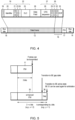
- FIG. 4 illustrates a CAN data frame 13 interposed between bus idle 14.
- the CAN data frame 13 can take the form of a CAN 2.0 (or "standard") data frame, a CAN-FD frame or CAN-XL frame. All CAN frame formats comprising an end portion 16 of the CAN frame 13 and ITM 17.
- the CAN data frame 13 includes a start of frame bit 18, an arbitration field 19 comprising an identifier 20 and remote transmission request (RTR) bit 21, a control field 22 comprising identifier extension bit (IDE) 23, reserved bit 24 and data length code (DLC) fields 25, a data field 26, a CRC field 27 comprising CRC sequence 28 and CRC delimiter 29, an ACK field 30 comprising an ACK slot 31 and an ACK delimiter 32, and end-of-frame 33.
- RTR remote transmission request
- IDE identifier extension bit
- DLC data length code
- the identifier 20 not only identifies the message, but also indicates priority. In the standard frame format shown in FIG. 4 , the identifier is 11-bits long. In extended frame format (not shown) of CAN 2.0 or CAN-FD (not shown), however, the identifier may be 11- or 29-bits long. In CAN-XL, the identifier is 11-bits long.
- the identifier 20 is used in normal frames 7 and for BE frames 8 (in other words, the identifier 20 for a BE frame 8 is the BE identifier 9).
- the CAN controller 5 after the CAN controller 5 has transmitted a normal frame 7 and if it has further frame (normal or BE frame) to transmit, then it can start arbitration with the aim of transmitting the further frame after the end of ITM 17.
- an extended ITM 35 is used, extended by x bits, where x is 2 bits.
- the extended ITM 35 is used to ascertain whether there is any other node with lower BE-ID having data to transmit.
- a normal CAN frame 7 or a first BE frame 8 can be transmitted after the end of the ITM 17.
- any node 2 which sent a (first) BE frame 8 may be configured to wait at least for end of the extended ITM 35 before continuing with a second or subsequent BE frame 8 having the same CAN identifier 9, 20.
- BE FSM finite state machine
- the CAN controller 5 waits for a time (or "gap") 36 corresponding y bits.
- the gap 36 delays the transmission of the next BE frame 8 to allow proper enhanced ITM detection by all nodes.
- a node could start transmitting a normal frame 7 close to the end of the enhanced ITM 35.
- some nodes 2 can stay in a wait state while others start their next round of next BE data transmission.
- the extended ITM 35 and gap 36 are only visible once per BE transmission round. Using this approach, just one single BE transmission talker can still utilize nearly 100% of the CAN bus.
- a BE FSM 40 in the CAN controller 5 control when the CAN controller 5 can use its BE identifier 9 ( FIG. 2 ) for bus arbitration. If a CAN controller 5 ( FIG. 2 ) is assigned or uses more than one BE identifier 9 ( FIG. 2 ), then more than one FSM 40 is used, one for each BE identifier 9.
- the BE FSM 40 has first, second and third states 41, 42, 43.
- a first state 41 (herein also referred to as "BE-active"), it is permitted to use the BE identifier 9 for bus arbitration with a view to transmitting a BE frame 8 using the same transmission selection and arbitration mechanism as normal frames, e.g., the priority based transmit resource selection.
- the BE FSM 40 transitions to a second state 42 (herein also referred to as "BE-wait"). In the BE-wait state 42, it is not permitted to use the BE identifier 9.
- BE-wait state 42 is used for extended ITM 35 ( FIG. 5 ) detection.
- the BE FSM 40 transitions to a third state 43 (herein also referred to as "BE-gap").
- BE-gap a third state 43
- the BE- gap state 43 is used to compensate for inaccuracies of ITM measurement in different nodes on the physical CAN bus.
- the value of x and the period of time t is fixed for the network 1, i . e ., is common to all nodes 2 ( FIG. 1 ) on the bus 3. The values may differ, however, from bus to bus.
- the value of x and the period of time t are preferably configurable, for example, via configuration registers (not shown) in the CAN controller 2 ( FIG. 1 ).
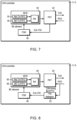
- a first CAN controller 5 1 is shown.
- the BE FSM 40 can be implemented in such a way that it is effectively integrated into a CAN protocol engine. This can help to reliably detect the enhanced ITM 35 ( FIG. 5 ).
- the BE FSM 40 is implemented in hardware, i . e ., in hardware logic.
- the first CAN controller 51 includes a CAN protocol engine (PRT) 52, the BE FSM 40, a CAN message handler (MHD) 54 which includes at least two transmit resources (or "Tx-FIFO") 55, 56 including a first transmit resource 55 for normal traffic and a second transmit resource 56 for BE traffic.
- a resource for BE traffic has the benefit that there is no head of chain blocking, in this case, the BE ID 9 is indirectly defined by the CAN frames placed by software in this resource for transmission.
- the message handler 54 also includes a selector 57 for selecting a transmit buffer 55, 56 as a source of data to pass to the protocol engine 52 based on the presence of data in the transmit resource and priority.
- the CAN protocol engine 52 and CAN message handler 54 are implemented in hardware.
- the CAN transceiver 6 ( FIG. 2 ) outputs a CAN receive data signal RXD which is passed to the PRT 52.
- the CAN protocol engine 52 is arranged to inspect the receive data signal RXD to detect enhanced ITM 35 and, if so detected, output an enhanced ITM detected signal Enh-ITM to the BE FSM 40.
- the BE FSM 40 waits until it is in the BE-active state 41 ( FIG. 6 ) before signalling to the message handler 54 that transmission of a BE frame 8 (if present) in the transmit buffer 56 can occur.
- the BE allowed signal can be used in the message handler 54 for a special CAN ID or dedicated transmit resource 56.
- the message handler 54 includes logic (not shown) arranged to exclude the resource 56 and BE ID 9 while BE-allowed signal is 0 to prevent BE frames 8 being provided to the CAN protocol engine 52 for arbitration except in BE active state.
- the BE FSM 40 does not affect transmission of normal frames 7 ( FIG. 2 ). Normal frame transmission is still possible after normal ITM 17 ( FIG. 5 ).
- a second CAN controller 5 2 is shown.
- the BE FSM 40 can be implemented in software, supported by timers.
- the second CAN controller 52 includes a CAN protocol engine (PRT) 62, an enhanced ITM detection unit 63, the BE FSM 40, and a CAN message handler (MHD) 64 which includes at least two transmit resources (or "Tx-FIFO") 65, 66 including a first transmit resource 65 for normal traffic and a second transmit resource 66 for BE traffic.
- the CAN protocol engine 62 and CAN message handler 64 are implemented in hardware.
- the CAN transceiver 6 ( FIG. 2 ) outputs a CAN receive data signal RXD which is passed to the PRT 62 and to the enhanced ITM detection unit 63.
- the CAN protocol engine 62 can output bit timing configuration to allow the ITM detection unit 63 to determine the duration of one bit.
- the enhanced ITM detection unit 63 is arranged to inspect the receive data signal RXD to detect enhanced ITM phase 35 ( i . e ., by sampling 3+y recessive bits) and, if so detected, outputs an enhanced ITM detected signal Enh-ITM to the BE FSM 40.
- the BE FSM 40 waits until it is in the BE-active state 41 ( FIG. 6 ) before signalling to the message handler 64 that bus arbitration to transmit a BE frame 8 (if present) in the transmit buffer 65 can occur.
- the BE allowed signal can be used in the message handler 64 for a special CAN ID or a dedicated transmit resource.
- the BE FSM 40 does not affect transmission of normal frames 7 ( FIG. 2 ). Normal frames 7 ( FIG. 2 ) is still possible after normal ITM 17 ( FIG. 5 ).
- the message handler 64 includes logic (not shown) arranged to prevent BE frames 8 being provided to the CAN protocol engine 62 for arbitration except in BE active state.
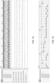
- FIGS. 9 to 15 illustrate simulations using Python script showing transmission of BE traffic in a model of a CAN network without and with the approach hereinbefore described.
- the model includes six nodes. Three of the nodes, first node Node 1, second node Node 2 and third node Node 3, transmit normal frames containing respective amounts (SIZE) of data and respective repetition rates (REP). Three of the nodes, fourth node Node 4, fifth node Node 5 and sixth node Node 6, transmit only BE traffic containing respective amounts (SIZE) of data.
- FIG. 9 illustrates which node currently transmits levels on the CAN bus bus, and which CAN ID is currently under transmission by an individual node tx (1), ..., tx (6).
- the first, second and third node generate normal, event triggered traffic taking up 60% bus load.
- the wait time is the time between software supplies the frame to the transmit resource and the frame being transmitted over the CAN bus.
- FIG. 10 illustrates how the transmit latency tx_latecy is calculated.
- FIG. 11 illustrates the levels on the CAN bus bus and transmit lines tx (1) ,..., tx (6) for each respective node, and the wait times tx_latecy (1), ..., tx_latecy (6) for each respective node in the base scenario.
- the latency distribution correlates with the bus priority IDs of the frames.
- FIG. 12 illustrates the levels on the CAN bus bus and transmit lines tx (1), ..., tx (6) for each respective node, and the wait times tx_latecy (1), ..., tx_latecy (6) for each respective node in an overload scenario with strict priority without BE traffic support ( i . e ., without BE enabled).
- Each of the fourth, fifth and sixth nodes Node 4, Node 5, Node 6 try to send about additional 30% bus load.
- the bus loads for the first, second and third nodes Node 1, Node 2, Node 3 are the same as in the base scenario.
- the bus is overloaded, and it is expected that not all BE frames are transmitted in time.
- the forth node Node 4 is able to send all its BE frames due the lower ID, as evidenced by the low numbers on tx_latecy (4).
- the fifth node Node 5 takes the remaining 10% of free bus, but is not able to send all its BE frames, as evidenced by the continuously increasing latency on tx_latecy (5).
- the sixth node Node 6 does not transmit any of its BE frames, as it has the lowest ID.
- FIG. 14 illustrates the levels on the CAN bus bus and transmit lines tx (1), ..., tx (6) for each respective node, and the wait times tx_latecy (1), ..., tx_latecy (6) for each respective node in an overload scenario with BE traffic support ( i . e ., with BE enabled).
- each of the fourth, fifth and sixth nodes Node 4, Node 5, Node 6 try to send about additional 30% bus load.
- the bus loads for the first, second and third nodes Node 1, Node 2, Node 3 are the same as in the base scenario.
- the bus is overloaded, and so it is expected that not all BE frames transmitted in time.
- FIG. 13 is a detailed view of FIG. 12 and illustrates levels on the CAN bus bus, and transmit lines tx (1), tx (2), tx (3), tx (4), tx (5), tx (6) for each respective node in the overload scenario without BE traffic support.
- FIG. 13 shows that the fifth node Node 5 only succeeds in accessing the bus when the fourth node Node 4 is quiet, and that the sixth node Node 6 never wins arbitration.
- FIG. 15 is a detailed view of FIG. 14 and illustrates levels on the CAN bus bus, and transmit lines tx (1), tx (2), tx (3), tx (4), tx (5), tx (6) for each respective node in the overload scenario with BE traffic support.
- FIG. 15 shows that although the fourth, fifth and sixth nodes Node 4, Node 5, Node 6 send some of their scheduled BE frames fairly until the bus is full.
- FIG. 15 also shows that after the sixth node Node 6 has transmitted its BE frame (indicated by an arrow), there is always an extended ITM and the fourth, fifth and sixth nodes Node 4, Node 5, Node 6 are allowed to send BE frames again. After this, arbitration between fourth, fifth and sixth nodes Node 4, Node 5, Node 6 takes place based on the normal strict priority scheme.
- the CAN controllers 5 herein described can be used in automotive and industrial applications.
- a motor vehicle 100 is shown in which the CAN network 1 is deployed.
- the approach can be implemented in software.
Landscapes
- Engineering & Computer Science (AREA)
- Computer Networks & Wireless Communication (AREA)
- Signal Processing (AREA)
- Quality & Reliability (AREA)
- Small-Scale Networks (AREA)
Abstract
Description
- The present invention relates to a CAN communication controller.
- Controller area network (CAN) is a serial communications protocol which was originally designed for use in automotive applications, but which has now been adopted in a wide variety of other fields including heating, ventilation and air conditioning (HVAC) control systems, process control systems and medical equipment.
- According to CAN, a node is able to transmit a message on a two-wire CAN bus when the bus is idle. Each message has a priority in the form of an identifier such that if two nodes transmit at the same time, then, through an arbitration process, the message having the lowest value takes priority and is transmitted, and the other message tries to re-transmit its message once the bus becomes idle again.
- CAN protocols, such as CAN 2.0, CAN-FD and CAN-XL, are optimised for event-triggered bus communication.
- There are disclosed techniques listed below.
- [Non-Patent Document 1] G. Cena and A. Valenzano: "Achieving Round-Robin Access in Controller Area Networks", IEEE Transactions on Industrial Electronics, volume 49, no. 6, pages 1202 to 1213 (2002).
- [Non-Patent Document 2] T. Beitelmal, A. El-Mahdi, and H. Abdulkarim: "New Technique to Enforce a Fair Behavior in Accessing the Medium in the Controller Area Network", 2nd International Conference on Electrical Systems Design & Technologies, Hammamet Tunisia, November 8-10, 2008.
- In heavy traffic conditions, not only do latencies become less predictable, but also CAN may exhibit unfair behaviour, in particular, when the control applications require the same quality of service for a number of different communication objects. Non-Patent
Document 1 describes an approach in which the number of times each communication object can be sent in any one frame burst (or "run") is limited. Reference is also made to Non-PatentDocument 2. - The approaches disclosed in
Non-Patent Document 1 and inNon-Patent Document 2, however, have at least one drawback namely losing the ability to impose strict priority which would appear to be one reason why such approaches have not been adopted. Indeed, automotive CAN networks and communication schedules generally require strict priority. To help achieve bounded latency times, the network is configured so that bus utilization is low (no more than 70%). - CAN may be deployed in situations in which other forms of data which are not event-triggered might be transmitted. These situations might only require "best effort" in which high latency might be tolerable. Although such data could in principle be transmitted using a CAN bus, it would be handled in the same way as event-triggered messages so increasing bus load and thus detrimentally affecting normal event-triggered messages. An ability to handle such data in CAN without such drawbacks would be desirable.
- According to a first aspect of the present invention there is provided a CAN communication controller for transmitting first and second types of frames wherein the first type of frame is used to transmit event-triggered communication data and the second type of frame is used to transmit best effort traffic data, the CAN communication controller configured, in response to transmitting a frame of the second type having a given identifier to delay arbitration of a following frame of the second type having the given identifier, and not to delay arbitration of a frame of the first type (or "allowing a frame of the first type to be transmitted in a normal way").
- This can allow best effort traffic (such as, diagnostic data or software download) to be transmitted on a CAN bus while minimising or even avoiding impact on event-triggered communication, while maintaining, increasing or maximising CAN bus utilization. The CAN communication controller may comply with CAN 2.0, CAN-FD and/or CAN-XL.
- The CAN communication controller may be configured, in response to transmitting a frame of the second type having another identifier which is different to the given identifier, to delay arbitration of a following frame of the second type having the other identifier.
- The CAN communication controller may be configured, in response to transmitting the frame of the second type having the given identifier, not to delay arbitration of a frame of the second type having another, different identifier to the given identifier.
- The CAN communication controller may be configured, in response to transmitting the frame of the second type having the given identifier to delay arbitration of the immediately (or "first") following frame of the second type having the given identifier (in other words, to delay arbitration of the immediately succeeding next frame with the same identifier).
- The CAN communication controller may be configured, in response to transmitting the frame of the second type having the given identifier to delay arbitration of the nth following frame where n ≥ 2) of the second type having the given identifier (in other words, not to delay arbitration of the immediately succeeding next frame with the same identifier, but of a later frame with the same identifier). This allows a short burst of best effort frames. Alternatively, the CAN communication controller may be configured, in response to transmitting the frame of the second type having the given identifier to delay arbitration after a predetermined amount of data is transmitted in at least one frame of with the same identifier. This allows a short burst of best effort frames and means that a node is able to send, for example, 1500 bytes of data in one frame or the same amount of data distributed between two or more frames (for instance, 5 frames each containing 300 bytes of data).
- The first type of frame may have an identifier assignable from a first, predetermined set of identifier values, and the second type of frame may have an identifier assignable from a second, predetermined set of identifier values. The first, predetermined set of identifier values may comprise a first, higher-priority range of identifier values and the second, predetermined set of identifier values may comprise a second, lower-priority range of identifier values.
- The CAN communication controller may be configured to delay arbitration by waiting a first period of time corresponding to x bits after intermission (ITM). For instance, x may be 2.
- The CAN communication controller may be further configured to wait a second period of time corresponding to a further y bits. For instance, y may be 1 or may be 2.
- The CAN communication controller may comprise a CAN protocol engine, a detector for detecting an end of an enhanced ITM, at least one finite state machine and a message handler. The enhanced ITM may include ITM and an additional x bits. The at least one finite state machine may include a finite state machine associated with the given identifier. The finite state machine associated with the given identifier may include a first state in which bus arbitration for the second type of frame having the given identifier is allowed and a second state in which bus arbitration for the second type of frame having the given identifier is not allowed. The message handler may include two or more transmit resources including a transmit resource for best effort traffic data having the given identifier.
- The finite state machine may be configured, in response to the controller transmitting the frame of the second type having the given identifier, to transition from the first state to the second state, the detector may be configured, in response to detecting the end of the enhanced ITM, signals the end of the enhanced ITM to the finite state machine, and the finite state machine may be configured, in response the detector signalling the end of the enhanced ITM, to transition out of the second state. The finite state machine may be configured to transition out of the second state into a third state in which bus arbitration for the second type of frame having the given identifier is not allowed, and the finite state machine may be configured, in response to waiting a period of time corresponding to y bits, to transition from the third state to the first state.
- The CAN communication controller can communicate with CAN communication controller(s) which are not suitable for transmitting the second type of frame and vice versa.
- According to a second aspect of the present invention there is provided a monolithic integrated circuit comprising at least one processor and memory, and the CAN communication controller of the first aspect.
- The at least one processor may execute software which provides data for communication by the CAN communication controller.
- The monolithic integrated circuit may be a microcontroller or a system on a chip.
- According to a third aspect of the present invention there is provided a vehicle (such as a motor vehicle), industrial system or medical system comprising a CAN bus, and a plurality of CAN nodes connected to the CAN bus. At least one of the CAN nodes comprises the CAN communication controller of the first aspect.
- According to a fourth aspect of the present invention there is provided a method of operating a CAN communication controller for transmitting first and second types of frames, wherein the first type of frame is used to transmit event-triggered communication data and the second type of frame is used to transmit best effort traffic data. The method comprises transmitting a frame of the second type having a given identifier and, in response thereto, delaying arbitration of a following frame (such as the immediately following frame) of the second type having the given identifier, and not delaying arbitration of a frame of the first type.
- The method may comprise not delaying arbitration of a frame of the second type having another, different identifier to the given identifier.
- The method may be a hardware-implemented method. The method may be a software-implemented method.
- Certain embodiments of the present invention will now be described, by way of example, with reference to the accompanying drawings, in which:
-
FIG. 1 is a schematic diagram of a CAN network including CAN nodes; -
FIG. 2 is a schematic block diagram of a CAN node capable of transmitting normal event-triggered CAN frames and best effort frames; -
FIG. 3 is an example of a range of identifier values; -
FIG. 4 is a CAN frame, an example of a CAN frame in the form of a standard CAN frame which includes ITM; -
FIG. 5 is a diagram of a normal ITM and an extended ITM followed by a gap; -
FIG. 6 is a state diagram of a finite state machine controlling when a CAN controller can use its best effort identifier; -
FIG. 7 is a schematic block diagram of a first CAN communications controller; -
FIG. 8 is a schematic block diagram of a second CAN communications controller; -
FIG. 9 is a diagram of simulated levels on a CAN bus and transmit lines of six nodes in a base scenario; -
FIG. 10 is a diagram of transmission of two frames, of different priorities; -
FIG. 11 is a diagram of simulated levels on a CAN bus, transmit lines of six nodes, and wait times for the six nodes in a base scenario for 50% bus utilization; -
FIG. 12 is a diagram of simulated levels on a CAN bus, transmit lines of six nodes, and wait times for the six nodes in an overload scenario with strict priority without BE traffic support; -
FIG. 13 is a diagram of simulated levels on a CAN bus, transmit lines of six nodes, and wait times for the six nodes in an overload scenario with strict priority with BE traffic support; -
FIG. 14 is a diagram of simulated levels on a CAN bus and transmit lines of six nodes in an overload scenario with strict priority without BE traffic support; -
FIG. 15 is a diagram of simulated levels on a CAN bus and transmit lines of six nodes in an overload scenario with strict priority with BE traffic support; and -
FIG. 16 is a schematic diagram of a motor vehicle and a CAN network deployed in the motor vehicle. - Data transmitted in a CAN may be generally divided into two types, namely event-triggered communication data having bounded or specified latency requirements, and data having no bounded latency. Data having no bounded latency (herein referred to as "best effort traffic" or simply "BE traffic") includes diagnostic data, software download, data from Ethernet-CAN gateways and data shaped by higher-level software (e.g., TCP).
- Communication on a CAN may be configured to handle best effort traffic by shaping the best effort traffic as event-triggered data. This approach, however, tends to be inefficient with CAN bus utilization limited to about 70%. By contrast, communication on an Ethernet (for example in AVB and TSN) can be optimized for coexisting event-triggered and best effort traffic. In such networks, QoS allows for up to 100% bus utilization.
- The present invention seeks to provide apparatus for and a method of transmitting best effort traffic in a CAN without impacting event-triggered communication, while maximising bus utilization.
- This can have one or more benefits, such as allowing quicker diagnostics, allowing fewer CAN buses to be used and allowing simpler CAN-Ethernet gateways to be employed since no translation to event triggered traffic is required.
- As will be explained hereinafter, a mechanism can be used which can distribute available bandwidth fairly between nodes on CAN bus, allowing node-based control of weight of traffic. The mechanism can be employed by nodes that support CAN 2.0, CAN FD or CAN XL communication. Moreover, the nodes on a CAN bus need not know whether other nodes support the mechanism.
- Referring to
FIG. 1 , aCAN system 1 is shown. TheCAN system 1 includes at least two CANnodes 2 connected to aCAN bus 3 comprising low and high lines CAN_L, CAN_H. - Referring to
FIG. 2 , aCAN node 2 comprises a microcontroller (MCU) or system-on-a-chip (SoC) 4. TheCAN node 2 comprise a CAN communication controller 5 (herein referred to simply as "CAN controller"), which can take the form of a peripheral module in the microcontroller or system-on-a-chip 4, and aCAN transceiver 6. TheCAN transceiver 6 also be included in the microcontroller or system-on-a-chip 4. - The
CAN controller 5 can transmit event-triggered, latency bounded CAN frames 7 (herein referred to as a "normal frame" or "a first type of frame"), and CANframes 8 having no bounded latency (herein referred to as a "best effort frame", "BE frame" or "second type of frame"). As will be explained in more detail hereinafter, best efforts (BE) are used to transmit BEframes 8 and to distribute CAN bus bandwidth fairly betweennodes 2 and, when aCAN controller 5 has BEframes 8 to transmit, bus arbitration is controlled by a BE FSM 40 (FIG. 6 ), whereas bus arbitration for normal frames remains unchanged. - Each
CAN controller 5 has its own one or more best effort CANidentifiers 9, for example, lying in a range of available CAN identifier values or specified in a table (not shown) of CAN identifier values or defined indirectly by the identifiers of the CAN frames that application software (not shown) stores in a dedicated transmit resource, e.g., BE Tx- FIFO 56 (FIG. 7 ). Expressed differently, if aCAN controller 5 has a dedicated BE transmit resource, all frames coming from the transmit resource will be transmitted as BE frames, independently of their identifier. - Referring also to
FIG. 3 , arange 10 of CAN ID values is shown which includes first and second ranges 11, 12 of CAN ID values. Thefirst range 11 of CAN ID values are reserved for event-triggered communication, i.e., fornormal frames 7. Thesecond range 12 of CAN ID values are of lower priority (by virtue of having larger values) and are used for best effort traffic, i.e., for BE frames 8. CAN ID values in the second range are referred to as "best effort CAN identifiers" or simply "BE IDs". - For
N nodes 2 in thenetwork 1, a BE identifier range of N CAN addresses (i.e., CAN identifiers) are assigned to theN nodes 2. Each identifier is unique (in the network) for eachnode 2, where 0 ≤ n ≤ N-1. Thus, in the case of CAN 2.0 in which an 11-bit identifier is used, a BE identifier ID(n) for the nth node is ID(n) = 2048-N- n. Therefore, for 24 nodes, theBE identifier range 12 is from 2024 to 2047. - Using the lowest-priority CAN IDs for best effort frames can help to avoid any effect on the higher-priority, scheduled CAN traffic. As will be explained in more detail hereinafter, the
CAN controller 5, having transmitted aframe 8 of BE traffic using aBE ID 9, temporarily suppresses using itsBE ID 9 for arbitration. This givesother nodes 2 with other, e.g., lower priority, BEIDs 9 the chance to send theirBE frame 8. - Best effort frames 8 need not necessarily have a low priority or a lower priority than
normal frames 7. -
FIG. 4 illustrates aCAN data frame 13 interposed between bus idle 14. TheCAN data frame 13 can take the form of a CAN 2.0 (or "standard") data frame, a CAN-FD frame or CAN-XL frame. All CAN frame formats comprising anend portion 16 of theCAN frame 13 andITM 17. - Referring to
FIG. 4 , theCAN data frame 13 includes a start offrame bit 18, anarbitration field 19 comprising anidentifier 20 and remote transmission request (RTR)bit 21, acontrol field 22 comprising identifier extension bit (IDE) 23, reservedbit 24 and data length code (DLC) fields 25, adata field 26, aCRC field 27 comprisingCRC sequence 28 andCRC delimiter 29, anACK field 30 comprising anACK slot 31 and anACK delimiter 32, and end-of-frame 33. - The
identifier 20 not only identifies the message, but also indicates priority. In the standard frame format shown inFIG. 4 , the identifier is 11-bits long. In extended frame format (not shown) of CAN 2.0 or CAN-FD (not shown), however, the identifier may be 11- or 29-bits long. In CAN-XL, the identifier is 11-bits long. Theidentifier 20 is used innormal frames 7 and for BE frames 8 (in other words, theidentifier 20 for aBE frame 8 is the BE identifier 9). - Referring also to
FIG. 5 , after theCAN controller 5 has transmitted anormal frame 7 and if it has further frame (normal or BE frame) to transmit, then it can start arbitration with the aim of transmitting the further frame after the end ofITM 17. - In the case in which the
CAN controller 5 has transmitted aBE frame 8, anextended ITM 35 is used, extended by x bits, where x is 2 bits. Theextended ITM 35 is used to ascertain whether there is any other node with lower BE-ID having data to transmit. Thus, anormal CAN frame 7 or afirst BE frame 8 can be transmitted after the end of theITM 17. However, anynode 2 which sent a (first) BEframe 8 may be configured to wait at least for end of theextended ITM 35 before continuing with a second orsubsequent BE frame 8 having thesame CAN identifier - As will be explained in more detail hereinafter, when a
BE frame 8 needs to be transmitted, whether a BE frame can be selected by the node for bus arbitration is controlled by a finite state machine (FSM) 40 (herein also referred to as "BE FSM") inFIG. 6 or other suitable logic. - Referring still to
FIG. 5 , theCAN controller 5 waits for a time (or "gap") 36 corresponding y bits. Thegap 36 delays the transmission of thenext BE frame 8 to allow proper enhanced ITM detection by all nodes. There is a possibility that a node could start transmitting anormal frame 7 close to the end of theenhanced ITM 35. In this rare case, somenodes 2 can stay in a wait state while others start their next round of next BE data transmission. Theextended ITM 35 andgap 36 are only visible once per BE transmission round. Using this approach, just one single BE transmission talker can still utilize nearly 100% of the CAN bus. - Referring to
FIG. 6 , aBE FSM 40 in the CAN controller 5 (FIG. 2 ) control when theCAN controller 5 can use its BE identifier 9 (FIG. 2 ) for bus arbitration. If a CAN controller 5 (FIG. 2 ) is assigned or uses more than one BE identifier 9 (FIG. 2 ), then more than oneFSM 40 is used, one for each BEidentifier 9. - The
BE FSM 40 has first, second andthird states - Referring to
FIGS. 2 and6 , in a first state 41 (herein also referred to as "BE-active"), it is permitted to use theBE identifier 9 for bus arbitration with a view to transmitting aBE frame 8 using the same transmission selection and arbitration mechanism as normal frames, e.g., the priority based transmit resource selection. - After the
BE frame 8 has been transmitted, theBE FSM 40 transitions to a second state 42 (herein also referred to as "BE-wait"). In theBE-wait state 42, it is not permitted to use theBE identifier 9. TheBE-wait state 42 is used for extended ITM 35 (FIG. 5 ) detection. - At the end of the extended ITM 35 (
FIG. 5 ), theBE FSM 40 transitions to a third state 43 (herein also referred to as "BE-gap"). In theBE-gap state 43, it is still not permitted to use theBE identifier 9. The BE-gap state 43 is used to compensate for inaccuracies of ITM measurement in different nodes on the physical CAN bus. - As hereinbefore described, the enhanced ITM 35 (
FIG. 5 ) is preferably 5-bits long (i.e., x = 2) and the gap 36 (FIG. 5 ) is preferably a period of time t that corresponds to 1 bit (i.e., y = 1). - The value of x and the period of time t is fixed for the
network 1, i.e., is common to all nodes 2 (FIG. 1 ) on thebus 3. The values may differ, however, from bus to bus. The value of x and the period of time t are preferably configurable, for example, via configuration registers (not shown) in the CAN controller 2 (FIG. 1 ). - Referring to
FIG. 7 , afirst CAN controller 51 is shown. - The
BE FSM 40 can be implemented in such a way that it is effectively integrated into a CAN protocol engine. This can help to reliably detect the enhanced ITM 35 (FIG. 5 ). Preferably, theBE FSM 40 is implemented in hardware, i.e., in hardware logic. - The first CAN controller 51 includes a CAN protocol engine (PRT) 52, the
BE FSM 40, a CAN message handler (MHD) 54 which includes at least two transmit resources (or "Tx-FIFO") 55, 56 including a first transmitresource 55 for normal traffic and a second transmitresource 56 for BE traffic. Defining a resource for BE traffic has the benefit that there is no head of chain blocking, in this case, theBE ID 9 is indirectly defined by the CAN frames placed by software in this resource for transmission. Themessage handler 54 also includes a selector 57 for selecting a transmitbuffer protocol engine 52 based on the presence of data in the transmit resource and priority. TheCAN protocol engine 52 andCAN message handler 54 are implemented in hardware. - The CAN transceiver 6 (
FIG. 2 ) outputs a CAN receive data signal RXD which is passed to thePRT 52. TheCAN protocol engine 52 is arranged to inspect the receive data signal RXD to detect enhancedITM 35 and, if so detected, output an enhanced ITM detected signal Enh-ITM to theBE FSM 40. - The
BE FSM 40 waits until it is in the BE-active state 41 (FIG. 6 ) before signalling to themessage handler 54 that transmission of a BE frame 8 (if present) in the transmitbuffer 56 can occur. - The BE allowed signal can be used in the
message handler 54 for a special CAN ID or dedicated transmitresource 56. - The
message handler 54 includes logic (not shown) arranged to exclude theresource 56 and BEID 9 while BE-allowed signal is 0 to prevent BEframes 8 being provided to theCAN protocol engine 52 for arbitration except in BE active state. - The
BE FSM 40 does not affect transmission of normal frames 7 (FIG. 2 ). Normal frame transmission is still possible after normal ITM 17 (FIG. 5 ). - Referring to
FIG. 8 , asecond CAN controller 52 is shown. - ITM detection can be done independently of the CAN protocol engine, particularly when longer times (e.g., x >2 and gap time t corresponds to more than y = 1) are defined. In this case, the
BE FSM 40 can be implemented in software, supported by timers. - The
second CAN controller 52 includes a CAN protocol engine (PRT) 62, an enhancedITM detection unit 63, theBE FSM 40, and a CAN message handler (MHD) 64 which includes at least two transmit resources (or "Tx-FIFO") 65, 66 including a first transmitresource 65 for normal traffic and a second transmitresource 66 for BE traffic. TheCAN protocol engine 62 andCAN message handler 64 are implemented in hardware. - The CAN transceiver 6 (
FIG. 2 ) outputs a CAN receive data signal RXD which is passed to thePRT 62 and to the enhancedITM detection unit 63. TheCAN protocol engine 62 can output bit timing configuration to allow theITM detection unit 63 to determine the duration of one bit. - The enhanced
ITM detection unit 63 is arranged to inspect the receive data signal RXD to detect enhanced ITM phase 35 (i.e., by sampling 3+y recessive bits) and, if so detected, outputs an enhanced ITM detected signal Enh-ITM to theBE FSM 40. - The
BE FSM 40 waits until it is in the BE-active state 41 (FIG. 6 ) before signalling to themessage handler 64 that bus arbitration to transmit a BE frame 8 (if present) in the transmitbuffer 65 can occur. - The BE allowed signal can be used in the
message handler 64 for a special CAN ID or a dedicated transmit resource. - The
BE FSM 40 does not affect transmission of normal frames 7 (FIG. 2 ). Normal frames 7 (FIG. 2 ) is still possible after normal ITM 17 (FIG. 5 ). - The
message handler 64 includes logic (not shown) arranged to prevent BEframes 8 being provided to theCAN protocol engine 62 for arbitration except in BE active state. -
FIGS. 9 to 15 illustrate simulations using Python script showing transmission of BE traffic in a model of a CAN network without and with the approach hereinbefore described. - The model includes six nodes. Three of the nodes,
first node Node 1,second node Node 2 andthird node Node 3, transmit normal frames containing respective amounts (SIZE) of data and respective repetition rates (REP). Three of the nodes,fourth node Node 4,fifth node Node 5 andsixth node Node 6, transmit only BE traffic containing respective amounts (SIZE) of data. - First node
- ID = 100, SIZE = 30, REP = 1 ms
- ID = 101, SIZE = 1000, REP = 2.5 ms
- Second node
- ID = 200, SIZE = 1200, REP = 3 ms
- ID = 201, SIZE = 900, REP = 3 ms
- ID = 203, SIZE = 100, REP = 3 ms
- Third node
- ID = 300, SIZE = 64, REP = 3 ms
- ID = 301, SIZE = 1550, REP = 3 ms
- Fourth node
ID = 804, SIZE = 600 - Fifth node
ID= 805, SIZE = 600 - Sixth node
ID=806, SIZE = 600 -
FIG. 9 illustrates which node currently transmits levels on the CAN bus bus, and which CAN ID is currently under transmission by an individual node tx (1), ..., tx (6). The ID=0 is simulation specific and means no activity. In total, the first, second and third node generate normal, event triggered traffic taking up 60% bus load. - The wait time is the time between software supplies the frame to the transmit resource and the frame being transmitted over the CAN bus.
-
FIG. 10 illustrates how the transmit latency tx_latecy is calculated. In this example of one node at t1 there are twoframes 87, 88 with ID=100 and ID=101 available in the message handler MHD for transmission. At t2, the protocol engine PRT brings theframe 87 with ID=100 onto the bus. After the end of this transmission, at t3, the frame 88 with ID=101 is sent on the bus. The tx_latecy, i.e., t2-t1 for the first frame 87 (with ID=100) and t3-t1 for the second frame 88 (ID=101), is the waiting time of the frame in the CAN controller. -
FIG. 11 illustrates the levels on the CAN bus bus and transmit lines tx (1) ,..., tx (6) for each respective node, and the wait times tx_latecy (1), ..., tx_latecy (6) for each respective node in the base scenario. The latency distribution correlates with the bus priority IDs of the frames. -
FIG. 12 illustrates the levels on the CAN bus bus and transmit lines tx (1), ..., tx (6) for each respective node, and the wait times tx_latecy (1), ..., tx_latecy (6) for each respective node in an overload scenario with strict priority without BE traffic support (i.e., without BE enabled). - Each of the fourth, fifth and
sixth nodes Node 4,Node 5,Node 6 try to send about additional 30% bus load. The bus loads for the first, second andthird nodes Node 1,Node 2,Node 3 are the same as in the base scenario. The bus is overloaded, and it is expected that not all BE frames are transmitted in time. - The
forth node Node 4 is able to send all its BE frames due the lower ID, as evidenced by the low numbers on tx_latecy (4). Thefifth node Node 5 takes the remaining 10% of free bus, but is not able to send all its BE frames, as evidenced by the continuously increasing latency on tx_latecy (5). Thesixth node Node 6 does not transmit any of its BE frames, as it has the lowest ID. -
FIG. 14 illustrates the levels on the CAN bus bus and transmit lines tx (1), ..., tx (6) for each respective node, and the wait times tx_latecy (1), ..., tx_latecy (6) for each respective node in an overload scenario with BE traffic support (i.e., with BE enabled). - Again, each of the fourth, fifth and
sixth nodes Node 4,Node 5,Node 6 try to send about additional 30% bus load. The bus loads for the first, second andthird nodes Node 1,Node 2,Node 3 are the same as in the base scenario. The bus is overloaded, and so it is expected that not all BE frames transmitted in time. - Although the fourth, fifth and
sixth nodes Node 4,Node 5,Node 6 cannot send all scheduled BE frames, they are all able to send their BE frames fairly until the bus is full, this is visible by the continuously and equal for all threenodes Node 4,Node 5,Node 6 increasing latency on tx_latecy (5), tx_latecy (6), tx_latecy (7). -
FIG. 13 is a detailed view ofFIG. 12 and illustrates levels on the CAN bus bus, and transmit lines tx (1), tx (2), tx (3), tx (4), tx (5), tx (6) for each respective node in the overload scenario without BE traffic support. -
FIG. 13 shows that thefifth node Node 5 only succeeds in accessing the bus when thefourth node Node 4 is quiet, and that thesixth node Node 6 never wins arbitration. -
FIG. 15 is a detailed view ofFIG. 14 and illustrates levels on the CAN bus bus, and transmit lines tx (1), tx (2), tx (3), tx (4), tx (5), tx (6) for each respective node in the overload scenario with BE traffic support. -
FIG. 15 shows that although the fourth, fifth andsixth nodes Node 4,Node 5,Node 6 send some of their scheduled BE frames fairly until the bus is full.FIG. 15 also shows that after thesixth node Node 6 has transmitted its BE frame (indicated by an arrow), there is always an extended ITM and the fourth, fifth andsixth nodes Node 4,Node 5,Node 6 are allowed to send BE frames again. After this, arbitration between fourth, fifth andsixth nodes Node 4,Node 5,Node 6 takes place based on the normal strict priority scheme. - The
CAN controllers 5 herein described can be used in automotive and industrial applications. - Referring to
FIG. 16 , amotor vehicle 100 is shown in which theCAN network 1 is deployed. - It will be appreciated that various modifications may be made to the embodiments hereinbefore described. Such modifications may involve equivalent and other features which are already known in the design, manufacture and use of CAN communication controllers and component parts thereof and which may be used instead of or in addition to features already described herein. Features of one embodiment may be replaced or supplemented by features of another embodiment.
- The approach can be implemented in software.
- Although claims have been formulated in this application to particular combinations of features, it should be understood that the scope of the disclosure of the present invention also includes any novel features or any novel combination of features disclosed herein either explicitly or implicitly or any generalization thereof, whether or not it relates to the same invention as presently claimed in any claim and whether or not it mitigates any or all of the same technical problems as does the present invention. The applicants hereby give notice that new claims may be formulated to such features and/or combinations of such features during the prosecution of the present application or of any further application derived therefrom.
Claims (15)
- A CAN communication controller for transmitting first and second types of frames, wherein the first type of frame is used to transmit event-triggered communication data and the second type of frame is used to transmit best effort traffic data, the CAN communication controller configured, in response to transmitting a frame of the second type having a given identifier, to delay arbitration of a following frame of the second type having the given identifier, and not to delay arbitration of a frame of the first type.
- The CAN communication controller of claim 1, wherein the CAN communication controller is configured, in response to transmitting the frame of the second type having the given identifier, not to delay arbitration of a frame of the second type having another, different identifier to the given identifier.
- The CAN communication controller of claim 1 or 2, wherein the CAN communication controller is configured, in response to transmitting the frame of the second type having the given identifier, to delay arbitration of the immediately following frame of the second type of frame having the given identifier.
- The CAN communication controller of any one of claims 1 to 3, wherein the first type of frame has an identifier assignable from a first, predetermined set of identifier values, and the second type of frame has an identifier assignable from a second, predetermined set of identifier values.
- The CAN communication controller of any one of claims 1 to 4, which is configured to delay arbitration by waiting a first period of time corresponding to x bits after ITM.
- The CAN communication controller of claim 5, wherein x = 2.
- The CAN communication controller of any one or claims 1 to 6, which is further configured to wait a second period of time corresponding to a further y bits.
- The CAN communication controller of claim 7, wherein y = 1.
- The CAN communication controller of any one of claims 1 to 8, comprising:• a CAN protocol engine;• a detector for detecting an end of an enhanced ITM that includes ITM and an additional x bits;• at least one finite state machine including a finite state machine associated with the given identifier which includes at least a first state in which bus arbitration for the second type of frame having the given identifier is allowed and a second state in which bus arbitration for the second type of frame is not allowed;• a message handler which includes a transmit resource for data best effort traffic data having the given identifier.
- The CAN communication controller of claim 9, wherein:- the finite state machine is configured, in response to the controller transmitting the frame of the second type having the given identifier, to transition from the first state to the second state,- the detector is configured, in response to detecting the end of the enhanced ITM, signals the end of the enhanced ITM to the finite state machine, and- the finite state machine is configured, in response the detector signalling the end of the enhanced ITM, to transition out of the second state.
- The CAN communication controller of claim 10, wherein:- the finite state machine is configured to transition out of the second state into a third state in which bus arbitration for the second type of frame having the given identifier is not allowed, and- the finite state machine is configured, in response to waiting a period of time corresponding to y bits, to transition from the third state to the first state.
- A monolithic integrated circuit comprising:• at least one processor;• memory; and• the CAN communication controller of any one of claims 1 to 11.
- A motor vehicle comprising:• a CAN bus; and• a plurality of CAN nodes connected to the CAN bus;wherein at least one of the CAN nodes comprises the CAN communication controller of any one of claims 1 to 12.
- A method of operating a CAN communication controller for transmitting first and second types of frames, wherein the first type of frame is used to transmit event-triggered communication data and the second type of frame is used to transmit best effort traffic data, the method comprising:• transmitting a frame of the second type having a given identifier and, in response thereto:• delaying arbitration of a following frame of the second type having the given identifier; and• not delaying arbitration of a frame of the first type.
- The method of claim 14, further comprising:• not delaying arbitration of a frame of the second type having another, different identifier to the given identifier.
Priority Applications (3)
| Application Number | Priority Date | Filing Date | Title |
|---|---|---|---|
| EP22187758.2A EP4312410B1 (en) | 2022-07-29 | 2022-07-29 | CAN communication control and method for operating a CAN communication control |
| CN202310767622.6A CN117478452A (en) | 2022-07-29 | 2023-06-27 | CAN communication controller and method of operating CAN communication controller |
| US18/362,000 US20240039756A1 (en) | 2022-07-29 | 2023-07-31 | Can communication controller and method of operating can communication controller |
Applications Claiming Priority (1)
| Application Number | Priority Date | Filing Date | Title |
|---|---|---|---|
| EP22187758.2A EP4312410B1 (en) | 2022-07-29 | 2022-07-29 | CAN communication control and method for operating a CAN communication control |
Publications (2)
| Publication Number | Publication Date |
|---|---|
| EP4312410A1 true EP4312410A1 (en) | 2024-01-31 |
| EP4312410B1 EP4312410B1 (en) | 2025-12-31 |
Family
ID=82781173
Family Applications (1)
| Application Number | Title | Priority Date | Filing Date |
|---|---|---|---|
| EP22187758.2A Active EP4312410B1 (en) | 2022-07-29 | 2022-07-29 | CAN communication control and method for operating a CAN communication control |
Country Status (3)
| Country | Link |
|---|---|
| US (1) | US20240039756A1 (en) |
| EP (1) | EP4312410B1 (en) |
| CN (1) | CN117478452A (en) |
Family Cites Families (10)
| Publication number | Priority date | Publication date | Assignee | Title |
|---|---|---|---|---|
| US5570355A (en) * | 1994-11-17 | 1996-10-29 | Lucent Technologies Inc. | Method and apparatus enabling synchronous transfer mode and packet mode access for multiple services on a broadband communication network |
| US6654833B1 (en) * | 1999-07-29 | 2003-11-25 | Micron Technology, Inc. | Bus arbitration |
| AU2001241654A1 (en) * | 2000-02-23 | 2001-09-03 | Microsoft Corporation | Quality of service over paths having a wireless-link |
| US7941149B2 (en) * | 2002-05-13 | 2011-05-10 | Misonimo Chi Acquistion L.L.C. | Multi-hop ultra wide band wireless network communication |
| US20150254198A1 (en) * | 2013-03-15 | 2015-09-10 | Google Inc. | Methods and apparatus related to bus arbitration within a multi-master system |
| ES2764212T3 (en) * | 2013-06-19 | 2020-06-02 | Schneider Electric Ind Sas | Universal Ethernet solution |
| US9984016B2 (en) * | 2016-01-06 | 2018-05-29 | Dell Products L.P. | Systems and methods for hardware arbitration of a communications bus |
| US10321344B2 (en) * | 2017-02-17 | 2019-06-11 | Cisco Technology, Inc. | System and method to facilitate troubleshooting and predicting application performance in wireless networks |
| EP3503485B1 (en) * | 2017-12-22 | 2023-01-25 | Marelli Europe S.p.A. | Method for managing traffic in a network based upon ethernet switches, vehicle, communication interface, and corresponding computer program product |
| US11811801B2 (en) * | 2019-08-21 | 2023-11-07 | Nokia Solutions And Networks Oy | Anomaly detection for microservices |
-
2022
- 2022-07-29 EP EP22187758.2A patent/EP4312410B1/en active Active
-
2023
- 2023-06-27 CN CN202310767622.6A patent/CN117478452A/en active Pending
- 2023-07-31 US US18/362,000 patent/US20240039756A1/en active Pending
Non-Patent Citations (3)
| Title |
|---|
| CENA GIANLUCA ET AL: "A Fair Access Mechanism to Support Fragmented Data Transfers in CAN", 2022 IEEE 18TH INTERNATIONAL CONFERENCE ON FACTORY COMMUNICATION SYSTEMS (WFCS), IEEE, 27 April 2022 (2022-04-27), pages 1 - 8, XP034128039, DOI: 10.1109/WFCS53837.2022.9779185 * |
| G. CENAA. VALENZANO: "Achieving Round-Robin Access in Controller Area Networks", IEEE TRANSACTIONS ON INDUSTRIAL ELECTRONICS, vol. 49, no. 6, 2002, pages 1202 - 1213, XP011073786 |
| T. BEITELMALA. EL-MAHDIH. ABDULKARIM: "New Technique to Enforce a Fair Behavior in Accessing the Medium in the Controller Area Network", INTERNATIONAL CONFERENCE ON ELECTRICAL SYSTEMS DESIGN & TECHNOLOGIES, HAMMAMET TUNISIA |
Also Published As
| Publication number | Publication date |
|---|---|
| CN117478452A (en) | 2024-01-30 |
| US20240039756A1 (en) | 2024-02-01 |
| EP4312410B1 (en) | 2025-12-31 |
Similar Documents
| Publication | Publication Date | Title |
|---|---|---|
| CN114026825B (en) | Emulating conflicts in wired local area networks and related systems, methods and devices | |
| US11362858B2 (en) | Method for transmitting data via a communication channel, correspondingly designed device and communication interface, as well as correspondingly designed computer program | |
| US7801173B2 (en) | Communication message conversion apparatus and communication message conversion method | |
| RU2415511C2 (en) | Gateway for automatically routing messages between buses | |
| US5960001A (en) | Apparatus and method for guaranteeing isochronous data flow on a CSMA/CD network | |
| CN112015161A (en) | Vehicle diagnostic communication device and method and system comprising same | |
| EP2882146B1 (en) | Data transmission device, communication control method, and communication control program | |
| US10965492B2 (en) | Method for transmitting data packets, controller and system having a controller | |
| US10200290B2 (en) | Station and method for serial data transmission using dynamic reprioritizing of data frames | |
| CN113785538B (en) | Media access for time-sensitive and best effort data packets and related systems, methods and devices | |
| JP4814950B2 (en) | Transmission / reception system, node, and communication method | |
| US10230656B2 (en) | Method and apparatus for controlling message over heterogeneous network | |
| US7120713B2 (en) | Systems and methods for interfacing legacy equipment to high-speed data buses | |
| US20240039756A1 (en) | Can communication controller and method of operating can communication controller | |
| Strobl et al. | Using Ethernet over powerline communication in automotive networks | |
| CN120074982A (en) | Subscriber station and method for deterministic communication in a serial bus system | |
| Lian et al. | Network protocols for networked control systems | |
| Hasnaoui et al. | An implementation of a proposed modification of CAN protocol on CAN fieldbus controller component for supporting a dynamic priority policy | |
| JP4909350B2 (en) | Message transmission method | |
| EP4401363B1 (en) | Physical layer collision avoidance device and method for performing emergency transmission thereof | |
| EP4718785A1 (en) | Transmitting ethernet frames with priority | |
| JP3613203B2 (en) | Cell transmission control circuit and method thereof | |
| CN120692234A (en) | CAN device, CAN system, and method for CAN device | |
| Yoo et al. | Unidirectional ring ethernet and media access controller with automatic relaying for low-complexity in-vehicle control network |
Legal Events
| Date | Code | Title | Description |
|---|---|---|---|
| PUAI | Public reference made under article 153(3) epc to a published international application that has entered the european phase |
Free format text: ORIGINAL CODE: 0009012 |
|
| STAA | Information on the status of an ep patent application or granted ep patent |
Free format text: STATUS: THE APPLICATION HAS BEEN PUBLISHED |
|
| AK | Designated contracting states |
Kind code of ref document: A1 Designated state(s): AL AT BE BG CH CY CZ DE DK EE ES FI FR GB GR HR HU IE IS IT LI LT LU LV MC MK MT NL NO PL PT RO RS SE SI SK SM TR |
|
| STAA | Information on the status of an ep patent application or granted ep patent |
Free format text: STATUS: REQUEST FOR EXAMINATION WAS MADE |
|
| 17P | Request for examination filed |
Effective date: 20240515 |
|
| RBV | Designated contracting states (corrected) |
Designated state(s): AL AT BE BG CH CY CZ DE DK EE ES FI FR GB GR HR HU IE IS IT LI LT LU LV MC MK MT NL NO PL PT RO RS SE SI SK SM TR |
|
| STAA | Information on the status of an ep patent application or granted ep patent |
Free format text: STATUS: EXAMINATION IS IN PROGRESS |
|
| 17Q | First examination report despatched |
Effective date: 20240925 |
|
| GRAP | Despatch of communication of intention to grant a patent |
Free format text: ORIGINAL CODE: EPIDOSNIGR1 |
|
| STAA | Information on the status of an ep patent application or granted ep patent |
Free format text: STATUS: GRANT OF PATENT IS INTENDED |
|
| INTG | Intention to grant announced |
Effective date: 20250909 |
|
| GRAS | Grant fee paid |
Free format text: ORIGINAL CODE: EPIDOSNIGR3 |
|
| GRAA | (expected) grant |
Free format text: ORIGINAL CODE: 0009210 |
|
| STAA | Information on the status of an ep patent application or granted ep patent |
Free format text: STATUS: THE PATENT HAS BEEN GRANTED |
|
| AK | Designated contracting states |
Kind code of ref document: B1 Designated state(s): AL AT BE BG CH CY CZ DE DK EE ES FI FR GB GR HR HU IE IS IT LI LT LU LV MC MK MT NL NO PL PT RO RS SE SI SK SM TR |
|
| REG | Reference to a national code |
Ref country code: CH Ref legal event code: F10 Free format text: ST27 STATUS EVENT CODE: U-0-0-F10-F00 (AS PROVIDED BY THE NATIONAL OFFICE) Effective date: 20251231 Ref country code: GB Ref legal event code: FG4D |
|
| REG | Reference to a national code |
Ref country code: DE Ref legal event code: R096 Ref document number: 602022027749 Country of ref document: DE |
|
| REG | Reference to a national code |
Ref country code: IE Ref legal event code: FG4D |
|
| REG | Reference to a national code |
Ref country code: LT Ref legal event code: MG9D |
|
| PG25 | Lapsed in a contracting state [announced via postgrant information from national office to epo] |
Ref country code: NO Free format text: LAPSE BECAUSE OF FAILURE TO SUBMIT A TRANSLATION OF THE DESCRIPTION OR TO PAY THE FEE WITHIN THE PRESCRIBED TIME-LIMIT Effective date: 20260331 |
|
| PG25 | Lapsed in a contracting state [announced via postgrant information from national office to epo] |
Ref country code: FI Free format text: LAPSE BECAUSE OF FAILURE TO SUBMIT A TRANSLATION OF THE DESCRIPTION OR TO PAY THE FEE WITHIN THE PRESCRIBED TIME-LIMIT Effective date: 20251231 Ref country code: HR Free format text: LAPSE BECAUSE OF FAILURE TO SUBMIT A TRANSLATION OF THE DESCRIPTION OR TO PAY THE FEE WITHIN THE PRESCRIBED TIME-LIMIT Effective date: 20251231 |
|
| PG25 | Lapsed in a contracting state [announced via postgrant information from national office to epo] |
Ref country code: RS Free format text: LAPSE BECAUSE OF FAILURE TO SUBMIT A TRANSLATION OF THE DESCRIPTION OR TO PAY THE FEE WITHIN THE PRESCRIBED TIME-LIMIT Effective date: 20260331 |
|
| PG25 | Lapsed in a contracting state [announced via postgrant information from national office to epo] |
Ref country code: LV Free format text: LAPSE BECAUSE OF FAILURE TO SUBMIT A TRANSLATION OF THE DESCRIPTION OR TO PAY THE FEE WITHIN THE PRESCRIBED TIME-LIMIT Effective date: 20251231 |
|
| PG25 | Lapsed in a contracting state [announced via postgrant information from national office to epo] |
Ref country code: BG Free format text: LAPSE BECAUSE OF FAILURE TO SUBMIT A TRANSLATION OF THE DESCRIPTION OR TO PAY THE FEE WITHIN THE PRESCRIBED TIME-LIMIT Effective date: 20251231 |
|
| REG | Reference to a national code |
Ref country code: NL Ref legal event code: MP Effective date: 20251231 |