EP4312343A1 - Balancing, precharge & active discharge operation of split hv battery systems in electric vehicles - Google Patents
Balancing, precharge & active discharge operation of split hv battery systems in electric vehicles Download PDFInfo
- Publication number
- EP4312343A1 EP4312343A1 EP23187328.2A EP23187328A EP4312343A1 EP 4312343 A1 EP4312343 A1 EP 4312343A1 EP 23187328 A EP23187328 A EP 23187328A EP 4312343 A1 EP4312343 A1 EP 4312343A1
- Authority
- EP
- European Patent Office
- Prior art keywords
- transmission line
- coupled
- battery
- negative
- positive
- Prior art date
- Legal status (The legal status is an assumption and is not a legal conclusion. Google has not performed a legal analysis and makes no representation as to the accuracy of the status listed.)
- Granted
Links
Images






Classifications
-
- B—PERFORMING OPERATIONS; TRANSPORTING
- B60—VEHICLES IN GENERAL
- B60L—PROPULSION OF ELECTRICALLY-PROPELLED VEHICLES; SUPPLYING ELECTRIC POWER FOR AUXILIARY EQUIPMENT OF ELECTRICALLY-PROPELLED VEHICLES; ELECTRODYNAMIC BRAKE SYSTEMS FOR VEHICLES IN GENERAL; MAGNETIC SUSPENSION OR LEVITATION FOR VEHICLES; MONITORING OPERATING VARIABLES OF ELECTRICALLY-PROPELLED VEHICLES; ELECTRIC SAFETY DEVICES FOR ELECTRICALLY-PROPELLED VEHICLES
- B60L58/00—Methods or circuit arrangements for monitoring or controlling batteries or fuel cells, specially adapted for electric vehicles
- B60L58/10—Methods or circuit arrangements for monitoring or controlling batteries or fuel cells, specially adapted for electric vehicles for monitoring or controlling batteries
- B60L58/18—Methods or circuit arrangements for monitoring or controlling batteries or fuel cells, specially adapted for electric vehicles for monitoring or controlling batteries of two or more battery modules
- B60L58/22—Balancing the charge of battery modules
-
- B—PERFORMING OPERATIONS; TRANSPORTING
- B60—VEHICLES IN GENERAL
- B60L—PROPULSION OF ELECTRICALLY-PROPELLED VEHICLES; SUPPLYING ELECTRIC POWER FOR AUXILIARY EQUIPMENT OF ELECTRICALLY-PROPELLED VEHICLES; ELECTRODYNAMIC BRAKE SYSTEMS FOR VEHICLES IN GENERAL; MAGNETIC SUSPENSION OR LEVITATION FOR VEHICLES; MONITORING OPERATING VARIABLES OF ELECTRICALLY-PROPELLED VEHICLES; ELECTRIC SAFETY DEVICES FOR ELECTRICALLY-PROPELLED VEHICLES
- B60L3/00—Electric devices on electrically-propelled vehicles for safety purposes; Monitoring operating variables, e.g. speed, deceleration or energy consumption
- B60L3/0023—Detecting, eliminating, remedying or compensating for drive train abnormalities, e.g. failures within the drive train
-
- B—PERFORMING OPERATIONS; TRANSPORTING
- B60—VEHICLES IN GENERAL
- B60L—PROPULSION OF ELECTRICALLY-PROPELLED VEHICLES; SUPPLYING ELECTRIC POWER FOR AUXILIARY EQUIPMENT OF ELECTRICALLY-PROPELLED VEHICLES; ELECTRODYNAMIC BRAKE SYSTEMS FOR VEHICLES IN GENERAL; MAGNETIC SUSPENSION OR LEVITATION FOR VEHICLES; MONITORING OPERATING VARIABLES OF ELECTRICALLY-PROPELLED VEHICLES; ELECTRIC SAFETY DEVICES FOR ELECTRICALLY-PROPELLED VEHICLES
- B60L50/00—Electric propulsion with power supplied within the vehicle
- B60L50/50—Electric propulsion with power supplied within the vehicle using propulsion power supplied by batteries or fuel cells
- B60L50/60—Electric propulsion with power supplied within the vehicle using propulsion power supplied by batteries or fuel cells using power supplied by batteries
-
- B—PERFORMING OPERATIONS; TRANSPORTING
- B60—VEHICLES IN GENERAL
- B60L—PROPULSION OF ELECTRICALLY-PROPELLED VEHICLES; SUPPLYING ELECTRIC POWER FOR AUXILIARY EQUIPMENT OF ELECTRICALLY-PROPELLED VEHICLES; ELECTRODYNAMIC BRAKE SYSTEMS FOR VEHICLES IN GENERAL; MAGNETIC SUSPENSION OR LEVITATION FOR VEHICLES; MONITORING OPERATING VARIABLES OF ELECTRICALLY-PROPELLED VEHICLES; ELECTRIC SAFETY DEVICES FOR ELECTRICALLY-PROPELLED VEHICLES
- B60L58/00—Methods or circuit arrangements for monitoring or controlling batteries or fuel cells, specially adapted for electric vehicles
- B60L58/10—Methods or circuit arrangements for monitoring or controlling batteries or fuel cells, specially adapted for electric vehicles for monitoring or controlling batteries
- B60L58/18—Methods or circuit arrangements for monitoring or controlling batteries or fuel cells, specially adapted for electric vehicles for monitoring or controlling batteries of two or more battery modules
-
- B—PERFORMING OPERATIONS; TRANSPORTING
- B60—VEHICLES IN GENERAL
- B60L—PROPULSION OF ELECTRICALLY-PROPELLED VEHICLES; SUPPLYING ELECTRIC POWER FOR AUXILIARY EQUIPMENT OF ELECTRICALLY-PROPELLED VEHICLES; ELECTRODYNAMIC BRAKE SYSTEMS FOR VEHICLES IN GENERAL; MAGNETIC SUSPENSION OR LEVITATION FOR VEHICLES; MONITORING OPERATING VARIABLES OF ELECTRICALLY-PROPELLED VEHICLES; ELECTRIC SAFETY DEVICES FOR ELECTRICALLY-PROPELLED VEHICLES
- B60L58/00—Methods or circuit arrangements for monitoring or controlling batteries or fuel cells, specially adapted for electric vehicles
- B60L58/10—Methods or circuit arrangements for monitoring or controlling batteries or fuel cells, specially adapted for electric vehicles for monitoring or controlling batteries
- B60L58/18—Methods or circuit arrangements for monitoring or controlling batteries or fuel cells, specially adapted for electric vehicles for monitoring or controlling batteries of two or more battery modules
- B60L58/21—Methods or circuit arrangements for monitoring or controlling batteries or fuel cells, specially adapted for electric vehicles for monitoring or controlling batteries of two or more battery modules having the same nominal voltage
-
- H—ELECTRICITY
- H01—ELECTRIC ELEMENTS
- H01M—PROCESSES OR MEANS, e.g. BATTERIES, FOR THE DIRECT CONVERSION OF CHEMICAL ENERGY INTO ELECTRICAL ENERGY
- H01M10/00—Secondary cells; Manufacture thereof
- H01M10/42—Methods or arrangements for servicing or maintenance of secondary cells or secondary half-cells
- H01M10/425—Structural combination with electronic components, e.g. electronic circuits integrated to the outside of the casing
- H01M10/4264—Structural combination with electronic components, e.g. electronic circuits integrated to the outside of the casing with capacitors
-
- H—ELECTRICITY
- H01—ELECTRIC ELEMENTS
- H01M—PROCESSES OR MEANS, e.g. BATTERIES, FOR THE DIRECT CONVERSION OF CHEMICAL ENERGY INTO ELECTRICAL ENERGY
- H01M10/00—Secondary cells; Manufacture thereof
- H01M10/42—Methods or arrangements for servicing or maintenance of secondary cells or secondary half-cells
- H01M10/44—Methods for charging or discharging
- H01M10/441—Methods for charging or discharging for several batteries or cells simultaneously or sequentially
-
- H—ELECTRICITY
- H02—GENERATION; CONVERSION OR DISTRIBUTION OF ELECTRIC POWER
- H02J—ELECTRIC POWER NETWORKS; CIRCUIT ARRANGEMENTS OR SYSTEMS FOR SUPPLYING OR DISTRIBUTING ELECTRIC POWER; SYSTEMS FOR STORING ELECTRIC ENERGY
- H02J7/00—Circuit arrangements for charging or discharging batteries or for supplying loads from batteries
- H02J7/50—Circuit arrangements for charging or discharging batteries or for supplying loads from batteries acting upon multiple batteries simultaneously or sequentially
- H02J7/52—Circuit arrangements for charging or discharging batteries or for supplying loads from batteries acting upon multiple batteries simultaneously or sequentially for charge balancing, e.g. equalisation of charge between batteries
- H02J7/54—Passive balancing, e.g. using resistors or parallel MOSFETs
-
- B—PERFORMING OPERATIONS; TRANSPORTING
- B60—VEHICLES IN GENERAL
- B60L—PROPULSION OF ELECTRICALLY-PROPELLED VEHICLES; SUPPLYING ELECTRIC POWER FOR AUXILIARY EQUIPMENT OF ELECTRICALLY-PROPELLED VEHICLES; ELECTRODYNAMIC BRAKE SYSTEMS FOR VEHICLES IN GENERAL; MAGNETIC SUSPENSION OR LEVITATION FOR VEHICLES; MONITORING OPERATING VARIABLES OF ELECTRICALLY-PROPELLED VEHICLES; ELECTRIC SAFETY DEVICES FOR ELECTRICALLY-PROPELLED VEHICLES
- B60L2270/00—Problem solutions or means not otherwise provided for
- B60L2270/20—Inrush current reduction, i.e. avoiding high currents when connecting the battery
-
- H—ELECTRICITY
- H01—ELECTRIC ELEMENTS
- H01M—PROCESSES OR MEANS, e.g. BATTERIES, FOR THE DIRECT CONVERSION OF CHEMICAL ENERGY INTO ELECTRICAL ENERGY
- H01M10/00—Secondary cells; Manufacture thereof
- H01M10/42—Methods or arrangements for servicing or maintenance of secondary cells or secondary half-cells
- H01M10/425—Structural combination with electronic components, e.g. electronic circuits integrated to the outside of the casing
- H01M2010/4271—Battery management systems including electronic circuits, e.g. control of current or voltage to keep battery in healthy state, cell balancing
-
- H—ELECTRICITY
- H01—ELECTRIC ELEMENTS
- H01M—PROCESSES OR MEANS, e.g. BATTERIES, FOR THE DIRECT CONVERSION OF CHEMICAL ENERGY INTO ELECTRICAL ENERGY
- H01M2220/00—Batteries for particular applications
- H01M2220/20—Batteries in motive systems, e.g. vehicle, ship, plane
-
- Y—GENERAL TAGGING OF NEW TECHNOLOGICAL DEVELOPMENTS; GENERAL TAGGING OF CROSS-SECTIONAL TECHNOLOGIES SPANNING OVER SEVERAL SECTIONS OF THE IPC; TECHNICAL SUBJECTS COVERED BY FORMER USPC CROSS-REFERENCE ART COLLECTIONS [XRACs] AND DIGESTS
- Y02—TECHNOLOGIES OR APPLICATIONS FOR MITIGATION OR ADAPTATION AGAINST CLIMATE CHANGE
- Y02T—CLIMATE CHANGE MITIGATION TECHNOLOGIES RELATED TO TRANSPORTATION
- Y02T10/00—Road transport of goods or passengers
- Y02T10/60—Other road transportation technologies with climate change mitigation effect
- Y02T10/70—Energy storage systems for electromobility, e.g. batteries
Definitions
- This application relates to High Voltage (HV) precharge, active discharge and balancing of a HV powertrain comprising two batteries in series.
- HV High Voltage
- the HV modules such as on-board chargers, DC-DC converters, traction inverters and HV auxiliary modules are connected after the main contactors, which are by default open when in a parking scenario.
- the main contactors are then closed during a charging or driving operation.
- the contactors are closed without precharging the input capacitances of the HV modules, an inrush of current through the main contactors can occur, which can lead to physical damage of the contactors and a possibility of a fire within the vehicle.
- the input capacitances of the HV modules are slowly charged up to a level where the voltage difference before and after the main contactors is less than a few tens of voltage amplitude.
- a precharge resistor and an extra switch are added across one of the main contactors to form a precharge circuit.
- split batteries e.g., more than one battery or series of batteries
- different levels of power consumption between the split batteries can create imbalance between the split batteries, requiring a balancing circuit in order to balance energy levels within the split battery.
- the demand for the above functions has led to the development and implementation of separate circuits for each function, leading to an increase in manufacture costs, manufacture time, and the physical size of HV powertrains.
- a circuit can comprise a first battery comprising a positive terminal coupled to a positive transmission line and a negative terminal coupled to a common node, wherein the positive transmission line comprises a first contactor, a second battery comprising a positive terminal coupled to the common node and a negative terminal coupled to a negative transmission line, wherein the negative transmission line comprises a second contactor, and a subcircuit coupled to the common node, to the positive transmission line, and to the negative transmission line.
- the subcircuit further comprises a first endpoint coupled to the common node, a second endpoint coupled to the negative transmission line between the second contactor and the negative terminal of a high voltage module, a third endpoint coupled to the negative transmission line between the second endpoint and the negative terminal of the high voltage modules, a fourth endpoint coupled to the positive transmission line between the positive terminal of the first battery and the first contactor, and a fifth endpoint coupled to the positive transmission line between the first contactor and the positive terminal of the high voltage module.
- the subcircuit further comprises a first metal-oxide-semiconductor field-effect transistor coupled to the fourth endpoint and to a first internal node, a second internal node, wherein the second internal node is coupled to the first internal node, and a third metal-oxide-semiconductor field-effect transistor coupled to the first internal node and to the fifth endpoint.
- the subcircuit further comprises a first capacitor coupled to the second endpoint and to a third internal node, an inductor coupled to the second internal node and to the third internal node, and a resistor coupled to the third metal-oxide-semiconductor field-effect transistor and to the fifth endpoint.
- the circuit further comprises a second capacitor coupled to the positive transmission line between the fourth endpoint and the first contactor and to the negative transmission line between the third endpoint and the negative terminal of the high voltage module.
- elements described above in connection with the disclose circuits can be embodied in different forms such as systems, devices, or other forms.
- An advantage of the disclosed circuit is that the subcircuit can enable precharge, active discharge, and battery balancing operations in a single subcircuit, as opposed to utilizing separate circuits as in existing designs.
- the disclosed embodiments can enable reduction in cost, size, material use, complexity and production time of power trains in electric vehicles.
- the disclosed subject matter is directed towards a single circuit capable of enabling precharge, active discharge, and balancing operations within a split battery electrical vehicle architecture.
- FIG. 1 illustrates a diagram of an example electric vehicle architecture 100 with a precharge circuit.
- architecture 100 comprises a battery 101, a positive current transmission line 102, a negative current transmission line 103, a first main contactor 104, a second main contactor 105, and one or more HV modules 107.
- first main contactor 104 and the second main contactor 105 are open.
- first main contactor 104 and the second main contactor 105 are closed, allowing current to flow from the battery 101 to the one or more HV modules 107.
- architecture 100 additionally comprises a precharge circuit 106.
- Precharge circuit 106 comprises a resistor 116 and a switch 117.
- switch 117 and second main contactor 105 are closed allowing current to flow through the resistor 116.
- the voltage difference before and after the first main contactor 104 is close to zero volts (e.g., less than a few tens of voltage amplitude)
- the first main contactor 104 is closed and the switch 117 is opened. After this, the battery 101 can then be charged or used.
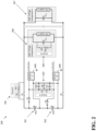
- FIG. 2 illustrates an example of an electric vehicle architecture 200 with separate precharge, balancing, and active discharge circuits.
- architecture 200 comprises a first battery 201 and a second battery 202.
- Architecture 200 also comprises precharge circuit 106 of architecture 100.
- Balance circuit 203 enables balancing operations between the first battery 201 and the second battery 202, wherein the first battery 201 can be used to charge the second battery 202 and vice versa.
- Active discharge circuit 205 enables discharge of the input capacitors of HV module 206.
- the use of separate precharge, balance, and active discharge circuits can lead to increased production cost, increased weight and/or increased production time.
- multiple HV modules may require additional active discharge circuits, depending on the usage and/or purpose of the additional HV modules.
- second HV module 207 may require a second active discharge circuit, depending on the second HV module's 207 purpose, thereby further increasing production cost, complexity, and vehicle weight.
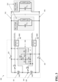
- FIG. 3 illustrates a diagram of a split battery architecture 300 with a subcircuit that enables precharge, active discharge and balance operations in accordance with one or more embodiments of the disclosed subject matter.
- architecture 300 can comprise a first battery 301 and a second battery 305.
- a positive terminal of the first battery 301 can be coupled to a positive transmission line 302 and a negative terminal of the first battery 301 can be coupled to a common node 304.
- a positive terminal of the second battery 305 can be coupled to the common node 304 and a negative terminal of the second battery 305 can be coupled to a negative transmission line 306.
- the positive transmission line 302 can comprise a first main contactor 303 and the negative transmission line 306 can comprise a second main contactor 307.
- Architecture 300 can comprise one or more HV modules 324 which can be coupled to the positive transmission line 302 and to the negative transmission line 306. Rather than having separate precharge, active discharge and balancing circuits as shown in FIG. 2 , Architecture 300 can comprise a subcircuit 320 coupled to the common node 304, to the positive transmission line 302 and to the negative transmission line 306. As described in greater detail below, subcircuit 320 enables precharge, active discharge and balancing operations within a single circuit, thereby simplifying architecture 300, decreasing production cost, decreasing overall physical size of architecture 300 and/or decreasing production time of architecture 300.
- FIG. 4 illustrates a diagram of a split battery architecture 400 with a subcircuit 320 that enables precharge, active discharge and balance operations in greater detail in accordance with one or more embodiments of the disclosed subject matter.
- subcircuit 320 can comprise a first endpoint 409 coupled to the common node 304, a second endpoint 410 coupled to the negative transmission line 306 between the second main contactor 307 and the HV modules 324, a third endpoint 411 coupled to the negative transmission line 306 between the second endpoint 410 and the HV modules 324, a fourth endpoint 412 coupled to the positive transmission line 302 between the positive terminal of the first battery 301 and the first main contactor 303, and a fifth endpoint 413 coupled to the positive transmission line 302 between the first main contactor 303 and the HV modules 324.
- the subcircuit 320 can further comprise a first metal-oxide-semiconductor field-effect transistor (MOFSET) 414 coupled to the fourth endpoint 412 and to a first internal node 415, a second MOFSET 416 coupled to the third endpoint 411 and to a second internal node 417, wherein the second internal node 417 is coupled to the first internal node 415, and a third MOFSET 418 coupled to the first internal node 415 and to the fifth endpoint 413.
- MOFSET metal-oxide-semiconductor field-effect transistor
- the subcircuit 320 can further comprise a first capacitor 419 coupled to the second endpoint 410 and to a third internal node 420, an inductor 421 coupled to the second internal node 417 and to the third internal node 420, and a resistor coupled to the third MOFSET 418 and to the fifth endpoint 413.
- Architecture 400 can additionally comprise a second capacitor 423 coupled to the positive transmission line 302 and to the negative transmission line 306.
- the second capacitor 423 can be coupled to the positive transmission line 302 between the fourth endpoint 412 and the first main contactor 303 and to the negative transmission line 306 between the third endpoint 411 and the HV modules 324.
- FIG. 5 illustrates a diagram of a precharge operation of architecture 400 in accordance with one or more embodiments of the disclosed subject matter.
- a precharging operation can be performed to reduce the inrush of current and prevent damage to the first main contactor 303, the second main contactor 307, and/or reduce risk of an electrical fire starting in the vehicle.
- the second main contactor 307 is closed and the first MOFSET 414 and the third MOFSET 418 are turned on, while the second MOFSET 416 is turned off.
- current flows according to the dashed line 501.
- the current flows through the resistor 422, the current is limited, thereby enabling precharging.
- a threshold e.g., within ten volts
- the first main contactor 303 can be closed and the first MOFSET 414 and the third MOFSET 418 can be turned off to enable driving or charging operations.
- FIG. 6 illustrates a diagram of an active discharge operation of a HV module in accordance with one or more embodiments of the disclosed subject matter.
- the first battery 301 and the second battery 305 are disconnected by opening the first main contactor 303 and the second main contactor 307. Accordingly, the energy stored in the input capacitors of the HV modules 324 can become a safety hazard to passengers in the vehicle and/or rescue personnel, if the HV modules 324 becomes exposed due to the crash or accident.
- the second MOFSET 416 and the third MOFSET 418 are turned on, while the first MOFSET 414 is turned off and the first main contactor 303 and the second main contactor 307 are disconnected.
- the second MOFSET 416 may be controlled using pulse-width modulation, either in a simple open loop or in a closed loop with voltage from the bus of the HV modules 324 as input for regulation.
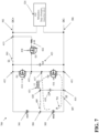
- FIG. 7 illustrates a diagram of energy from a second battery being stored in an inductor as part of a battery balancing operation.
- Balancing between two batteries can be done with two different control methods depending on the voltage difference between the two batteries. For example, natural balancing can be used to maintain an equal voltage in between two or more batteries, such as the first battery 301 and the second battery 305. Controlled balance can be used when the measured voltage of two batteries is equal, but the state of charge of the two batteries are different due to aspects such as connection resistance or the state of health of one of the batteries.
- the second MOFSET 416 In order to transfer power from the second battery 305 to the first battery 301, the second MOFSET 416 is turned on so that current flows according to dashed line 701. When the second MOFSET 416 is turned off, power is then stored in inductor 421.
- FIG. 8 illustrates a diagram of energy from an inductor being stored in a first battery as part of a battery balancing operation.
- the first MOFSET 414 is turned on to allow current to flow as shown by dashed line 801.
- the first MOFSET 414 is turned off, power is then stored in the first battery 301.
- the first MOFSET 414 and the second MOFSET 416 are switched on and off with a constant 50% duty cycle at each fixed switching frequency. In this way, the first battery 301 and the second battery 305 are automatically balanced until the voltage difference between the first battery 301 and the second battery 305 is close to 0V.
- first MOFSET 414 or the second MOFSET 416 is turned on first. After several switching cycles the battery with the lower voltage will charge from the battery with the higher voltage. Additionally, the first capacitor 419 and the second capacitor 423 can help to supply ripple currents when both the first MOFSET 414 and the second MOFSET 416 are switching on respectively in each switching cycle.
- a setpoint can be adjusted that changes the duty cycle. For example, rather than a 50/50 duty cycle as utilized in natural balancing, a setpoint other than 50/50 can be utilized depending on which battery needs to be charged and how fast. For example, rather than a 50/50 split, a 70/30 split can be utilized. Accordingly, the duty cycle of the first MOFSET 414 and the second MOFSET 416 are regulated based on the setpoint. This method enables the first battery 301 to charge the second battery 305, even if the voltage of the second battery 305 is higher.
- a method can comprise performing, by a single circuit, at least two operations of a plurality of operations wherein the plurality of operations comprise precharging an electric vehicle, active discharging the electric vehicle and battery balancing the electric vehicle, and wherein the single circuit can comprise a first battery coupled to a positive transmission line and a common node, a second battery coupled to a negative transmission line, and the common node, and a subcircuit coupled to the common node, to the positive transmission line, and to the negative transmission line.
- the at least two operations can comprise the precharging the electric vehicle, as described above in greater detail in reference to FIG. 5 , and the active discharging the electric vehicle, as described above in greater detail in reference to FIG. 6 .
- the at least two operations can comprise the precharging the electric vehicle and the battery balancing the electric vehicle, as described above in reference to FIGS. 7 and 8 .
- the at least two operations can comprise the active discharging the electric vehicle and the battery balancing the electric vehicle.
- the at least two operations can comprise three operations, wherein the three operations comprise the precharging the electric vehicle, the active discharging the electric vehicle, and the battery balancing the electric vehicle.
- FIG. 9 illustrates a flow diagram of a method 900 of manufacture of a circuit that comprises a single subcircuit that enables precharge, active discharge and balancing operations in accordance with the disclosed subject matter.
- method 900 can comprise coupling a positive terminal of a first battery to a positive transmission line and a negative terminal of the first battery to a common node, wherein the positive transmission line comprises a first contactor.
- method 900 can comprise coupling a positive terminal of a second battery to the common node and a negative terminal of the second battery to a negative transmission line, wherein the negative transmission line comprises a second contactor.
- method 900 can comprise coupling a subcircuit to the common node, to the positive transmission line and to the negative transmission line.
- method 900 can comprise coupling a positive terminal of a high voltage module to the positive transmission line and a negative terminal of the high voltage module to the negative transmission line.
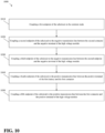
- FIG. 10 illustrates a flow diagram of a method 1000 of manufacture of a circuit that comprises a single subcircuit that enables precharge, active discharge and balancing operations in accordance with the disclosed subject matter.
- method 1000 can comprise coupling a first endpoint of the subcircuit of method 900 to the common node of method 900.
- method 1000 can comprise coupling a second endpoint of the subcircuit to the negative transmission line of method 900 between the second contactor and the negative terminal of the high voltage module of method 900.
- method 1000 can comprise coupling a third endpoint of the subcircuit to the negative transmission line between the second endpoint and the negative terminal of the high voltage module.
- method 1000 can comprise coupling a fourth endpoint of the subcircuit to the positive transmission line between the positive terminal of the first battery of method 900 and the first contactor.
- method 1000 can comprise coupling a fifth endpoint of the subcircuit to the positive transmission line between the first contactor and the positive terminal of the high voltage module.
- an electric vehicle architecture comprising a single subcircuit that enables precharge, active discharge and balancing operations, such as architecture 200 and 300, has several advantages. For example, by utilizing a single subcircuit as opposed to separate circuits for precharge, balance and active discharge operations, architectures 200 and 300 can reduce cost, weight, size and/or production times of electric vehicles. Additionally, the subcircuit enables greater scalability as it enables active discharge, rather than utilizing separate active discharge circuits located in one or several external HV modules. Furthermore, the subcircuit in architectures 200 and 300 offer improved reliability and are more resistant to damage. For example, the high frequency switching capacity used for active balance operations enables fast and controllable protection of the resistor used for precharge and discharge operations.
Landscapes
- Engineering & Computer Science (AREA)
- Power Engineering (AREA)
- Mechanical Engineering (AREA)
- Sustainable Development (AREA)
- Sustainable Energy (AREA)
- Transportation (AREA)
- Life Sciences & Earth Sciences (AREA)
- Manufacturing & Machinery (AREA)
- Chemical & Material Sciences (AREA)
- Chemical Kinetics & Catalysis (AREA)
- Electrochemistry (AREA)
- General Chemical & Material Sciences (AREA)
- Microelectronics & Electronic Packaging (AREA)
- Charge And Discharge Circuits For Batteries Or The Like (AREA)
- Electric Propulsion And Braking For Vehicles (AREA)
Abstract
Description
- This application relates to High Voltage (HV) precharge, active discharge and balancing of a HV powertrain comprising two batteries in series.
- In existing electric vehicle architecture, the HV modules, such as on-board chargers, DC-DC converters, traction inverters and HV auxiliary modules are connected after the main contactors, which are by default open when in a parking scenario. The main contactors are then closed during a charging or driving operation. However, if the contactors are closed without precharging the input capacitances of the HV modules, an inrush of current through the main contactors can occur, which can lead to physical damage of the contactors and a possibility of a fire within the vehicle. To prevent this, the input capacitances of the HV modules are slowly charged up to a level where the voltage difference before and after the main contactors is less than a few tens of voltage amplitude. For this operation, a precharge resistor and an extra switch are added across one of the main contactors to form a precharge circuit.
- Additionally, there is a need for discharging of these charged input capacitances. If the electric vehicle is involved in a crash or accident, the HV modules may become exposed, leading to the possibility of an electric shock to anyone who touches a live metal part of the vehicle during a rescue scenario. Accordingly, there is also a need for an active discharge circuit in order to discharge the capacitances of all the HV modules.
- Furthermore, automotive manufactures are moving towards electric vehicle architectures with split batteries (e.g., more than one battery or series of batteries) in order to provide better redundancy and reliability. However, different levels of power consumption between the split batteries can create imbalance between the split batteries, requiring a balancing circuit in order to balance energy levels within the split battery. The demand for the above functions has led to the development and implementation of separate circuits for each function, leading to an increase in manufacture costs, manufacture time, and the physical size of HV powertrains.
- The following presents a summary to provide a basic understanding of one or more embodiments of the invention. This summary is not intended to identify key or critical elements or delineate any scope of the different embodiments or any scope of the claims. Its sole purpose is to present concepts in a simplified form as a prelude to the more detailed description that is presented later. In one or more embodiments described herein, systems, circuits and/or devices are presented that enable precharge, active discharge and balancing operations in a single subcircuit within an electrical vehicle architecture.
- According to one or more embodiments, a circuit is provided. The circuit can comprise a first battery comprising a positive terminal coupled to a positive transmission line and a negative terminal coupled to a common node, wherein the positive transmission line comprises a first contactor, a second battery comprising a positive terminal coupled to the common node and a negative terminal coupled to a negative transmission line, wherein the negative transmission line comprises a second contactor, and a subcircuit coupled to the common node, to the positive transmission line, and to the negative transmission line.
- In some embodiments, the subcircuit further comprises a first endpoint coupled to the common node, a second endpoint coupled to the negative transmission line between the second contactor and the negative terminal of a high voltage module, a third endpoint coupled to the negative transmission line between the second endpoint and the negative terminal of the high voltage modules, a fourth endpoint coupled to the positive transmission line between the positive terminal of the first battery and the first contactor, and a fifth endpoint coupled to the positive transmission line between the first contactor and the positive terminal of the high voltage module.
- In some embodiments, the subcircuit further comprises a first metal-oxide-semiconductor field-effect transistor coupled to the fourth endpoint and to a first internal node, a second internal node, wherein the second internal node is coupled to the first internal node, and a third metal-oxide-semiconductor field-effect transistor coupled to the first internal node and to the fifth endpoint.
- In some embodiments, the subcircuit further comprises a first capacitor coupled to the second endpoint and to a third internal node, an inductor coupled to the second internal node and to the third internal node, and a resistor coupled to the third metal-oxide-semiconductor field-effect transistor and to the fifth endpoint.
- In some embodiments, the circuit further comprises a second capacitor coupled to the positive transmission line between the fourth endpoint and the first contactor and to the negative transmission line between the third endpoint and the negative terminal of the high voltage module.
- In some embodiments, elements described above in connection with the disclose circuits can be embodied in different forms such as systems, devices, or other forms.
- An advantage of the disclosed circuit is that the subcircuit can enable precharge, active discharge, and battery balancing operations in a single subcircuit, as opposed to utilizing separate circuits as in existing designs. By utilizing a single subcircuit, the disclosed embodiments can enable reduction in cost, size, material use, complexity and production time of power trains in electric vehicles.
-
-
FIG. 1 illustrates a diagram of a precharge circuit. -
FIG. 2 illustrates a diagram of a split battery architecture. -
FIG. 3 illustrates a diagram of a split battery architecture with a subcircuit that enables precharge, discharge and balance operations. -
FIG. 4 illustrates a diagram of a split battery architecture with a subcircuit that enables precharge, discharge and balance operations. -
FIG. 5 illustrates a diagram of a precharge operation. -
FIG. 6 illustrates a diagram of an active discharge operation of a HV module. -
FIGS. 7 and8 illustrate diagrams of balancing operations. -
FIGS. 9 and10 illustrate flow diagrams of methods of manufacture of a system that enables precharge, active discharge and balance operations. - The following detailed description is merely illustrative and is not intended to limit embodiments and/or application or uses of embodiments. Furthermore, there is no intention to be bound by any expressed or implied information presented in the preceding Summary section or in the Detailed Description section.
- The disclosed subject matter is directed towards a single circuit capable of enabling precharge, active discharge, and balancing operations within a split battery electrical vehicle architecture.
- Turning now to the drawings,
FIG. 1 illustrates a diagram of an exampleelectric vehicle architecture 100 with a precharge circuit. For example,architecture 100 comprises abattery 101, a positivecurrent transmission line 102, a negativecurrent transmission line 103, a firstmain contactor 104, a secondmain contactor 105, and one ormore HV modules 107. When the vehicle is in a parking scenario, the firstmain contactor 104 and the secondmain contactor 105 are open. However, when the vehicle is in operation or being charged, the firstmain contactor 104 and the secondmain contactor 105 are closed, allowing current to flow from thebattery 101 to the one ormore HV modules 107. This can lead to an inrush of current which can damage the firstmain contactor 104, the secondmain contactor 105 and/or start a fire within the vehicle. Accordingly,architecture 100 additionally comprises aprecharge circuit 106.Precharge circuit 106 comprises aresistor 116 and aswitch 117. During a precharge operation,switch 117 and secondmain contactor 105 are closed allowing current to flow through theresistor 116. Once the voltage difference before and after the firstmain contactor 104 is close to zero volts (e.g., less than a few tens of voltage amplitude), the firstmain contactor 104 is closed and theswitch 117 is opened. After this, thebattery 101 can then be charged or used. -
FIG. 2 illustrates an example of anelectric vehicle architecture 200 with separate precharge, balancing, and active discharge circuits. For example,architecture 200 comprises afirst battery 201 and asecond battery 202.Architecture 200 also comprisesprecharge circuit 106 ofarchitecture 100.Balance circuit 203 enables balancing operations between thefirst battery 201 and thesecond battery 202, wherein thefirst battery 201 can be used to charge thesecond battery 202 and vice versa.Active discharge circuit 205 enables discharge of the input capacitors ofHV module 206. As shown, the use of separate precharge, balance, and active discharge circuits can lead to increased production cost, increased weight and/or increased production time. Additionally, multiple HV modules may require additional active discharge circuits, depending on the usage and/or purpose of the additional HV modules. For example,second HV module 207 may require a second active discharge circuit, depending on the second HV module's 207 purpose, thereby further increasing production cost, complexity, and vehicle weight. -
FIG. 3 illustrates a diagram of asplit battery architecture 300 with a subcircuit that enables precharge, active discharge and balance operations in accordance with one or more embodiments of the disclosed subject matter. In an embodiment,architecture 300 can comprise afirst battery 301 and asecond battery 305. A positive terminal of thefirst battery 301 can be coupled to apositive transmission line 302 and a negative terminal of thefirst battery 301 can be coupled to acommon node 304. Similarly, a positive terminal of thesecond battery 305 can be coupled to thecommon node 304 and a negative terminal of thesecond battery 305 can be coupled to anegative transmission line 306. Thepositive transmission line 302 can comprise a firstmain contactor 303 and thenegative transmission line 306 can comprise a secondmain contactor 307.Architecture 300 can comprise one ormore HV modules 324 which can be coupled to thepositive transmission line 302 and to thenegative transmission line 306. Rather than having separate precharge, active discharge and balancing circuits as shown inFIG. 2 ,Architecture 300 can comprise asubcircuit 320 coupled to thecommon node 304, to thepositive transmission line 302 and to thenegative transmission line 306. As described in greater detail below,subcircuit 320 enables precharge, active discharge and balancing operations within a single circuit, thereby simplifyingarchitecture 300, decreasing production cost, decreasing overall physical size ofarchitecture 300 and/or decreasing production time ofarchitecture 300. -
FIG. 4 illustrates a diagram of asplit battery architecture 400 with asubcircuit 320 that enables precharge, active discharge and balance operations in greater detail in accordance with one or more embodiments of the disclosed subject matter. In an embodiment,subcircuit 320 can comprise afirst endpoint 409 coupled to thecommon node 304, asecond endpoint 410 coupled to thenegative transmission line 306 between the secondmain contactor 307 and theHV modules 324, athird endpoint 411 coupled to thenegative transmission line 306 between thesecond endpoint 410 and theHV modules 324, afourth endpoint 412 coupled to thepositive transmission line 302 between the positive terminal of thefirst battery 301 and the firstmain contactor 303, and afifth endpoint 413 coupled to thepositive transmission line 302 between the firstmain contactor 303 and theHV modules 324. - The
subcircuit 320 can further comprise a first metal-oxide-semiconductor field-effect transistor (MOFSET) 414 coupled to thefourth endpoint 412 and to a firstinternal node 415, asecond MOFSET 416 coupled to thethird endpoint 411 and to a secondinternal node 417, wherein the secondinternal node 417 is coupled to the firstinternal node 415, and athird MOFSET 418 coupled to the firstinternal node 415 and to thefifth endpoint 413. - Additionally, in an embodiment, the
subcircuit 320 can further comprise afirst capacitor 419 coupled to thesecond endpoint 410 and to a thirdinternal node 420, aninductor 421 coupled to the secondinternal node 417 and to the thirdinternal node 420, and a resistor coupled to thethird MOFSET 418 and to thefifth endpoint 413.Architecture 400 can additionally comprise asecond capacitor 423 coupled to thepositive transmission line 302 and to thenegative transmission line 306. In an embodiment, thesecond capacitor 423 can be coupled to thepositive transmission line 302 between thefourth endpoint 412 and the firstmain contactor 303 and to thenegative transmission line 306 between thethird endpoint 411 and theHV modules 324. -
FIG. 5 illustrates a diagram of a precharge operation ofarchitecture 400 in accordance with one or more embodiments of the disclosed subject matter. For example, when thefirst battery 301 and thesecond battery 305 need to be connected to theHV modules 324, a precharging operation can be performed to reduce the inrush of current and prevent damage to the firstmain contactor 303, the secondmain contactor 307, and/or reduce risk of an electrical fire starting in the vehicle. For a precharge operation, the secondmain contactor 307 is closed and thefirst MOFSET 414 and thethird MOFSET 418 are turned on, while thesecond MOFSET 416 is turned off. During the precharge operation, current flows according to the dashedline 501. As the current flows through theresistor 422, the current is limited, thereby enabling precharging. Once the voltage on either side of the firstmain contactor 303 is close to a threshold (e.g., within ten volts), the firstmain contactor 303 can be closed and thefirst MOFSET 414 and thethird MOFSET 418 can be turned off to enable driving or charging operations. -
FIG. 6 illustrates a diagram of an active discharge operation of a HV module in accordance with one or more embodiments of the disclosed subject matter. During a crash or accident scenario, thefirst battery 301 and thesecond battery 305 are disconnected by opening the firstmain contactor 303 and the secondmain contactor 307. Accordingly, the energy stored in the input capacitors of theHV modules 324 can become a safety hazard to passengers in the vehicle and/or rescue personnel, if theHV modules 324 becomes exposed due to the crash or accident. To perform a discharge operation, thesecond MOFSET 416 and thethird MOFSET 418 are turned on, while thefirst MOFSET 414 is turned off and the firstmain contactor 303 and the secondmain contactor 307 are disconnected. The current stored in the input capacitors of theHV modules 324 can then flow according to the dashedline 601 to discharge the current. In some scenarios, unexpected excess energy from theHV modules 324 can damage theresistor 422. Accordingly, in an embodiment, thesecond MOFSET 416 may be controlled using pulse-width modulation, either in a simple open loop or in a closed loop with voltage from the bus of theHV modules 324 as input for regulation. -
FIG. 7 illustrates a diagram of energy from a second battery being stored in an inductor as part of a battery balancing operation. Balancing between two batteries can be done with two different control methods depending on the voltage difference between the two batteries. For example, natural balancing can be used to maintain an equal voltage in between two or more batteries, such as thefirst battery 301 and thesecond battery 305. Controlled balance can be used when the measured voltage of two batteries is equal, but the state of charge of the two batteries are different due to aspects such as connection resistance or the state of health of one of the batteries. In order to transfer power from thesecond battery 305 to thefirst battery 301, thesecond MOFSET 416 is turned on so that current flows according to dashedline 701. When thesecond MOFSET 416 is turned off, power is then stored ininductor 421. -
FIG. 8 illustrates a diagram of energy from an inductor being stored in a first battery as part of a battery balancing operation. Once power has been stored ininductor 421 as shown inFIG. 7 , thefirst MOFSET 414 is turned on to allow current to flow as shown by dashedline 801. Once thefirst MOFSET 414 is turned off, power is then stored in thefirst battery 301. During natural balancing, thefirst MOFSET 414 and thesecond MOFSET 416 are switched on and off with a constant 50% duty cycle at each fixed switching frequency. In this way, thefirst battery 301 and thesecond battery 305 are automatically balanced until the voltage difference between thefirst battery 301 and thesecond battery 305 is close to 0V. It should be appreciated that is does not matter whether thefirst MOFSET 414 or thesecond MOFSET 416 is turned on first. After several switching cycles the battery with the lower voltage will charge from the battery with the higher voltage. Additionally, thefirst capacitor 419 and thesecond capacitor 423 can help to supply ripple currents when both thefirst MOFSET 414 and thesecond MOFSET 416 are switching on respectively in each switching cycle. In order to perform controlled balancing, a setpoint can be adjusted that changes the duty cycle. For example, rather than a 50/50 duty cycle as utilized in natural balancing, a setpoint other than 50/50 can be utilized depending on which battery needs to be charged and how fast. For example, rather than a 50/50 split, a 70/30 split can be utilized. Accordingly, the duty cycle of thefirst MOFSET 414 and thesecond MOFSET 416 are regulated based on the setpoint. This method enables thefirst battery 301 to charge thesecond battery 305, even if the voltage of thesecond battery 305 is higher. - Accordingly, a method can comprise performing, by a single circuit, at least two operations of a plurality of operations wherein the plurality of operations comprise precharging an electric vehicle, active discharging the electric vehicle and battery balancing the electric vehicle, and wherein the single circuit can comprise a first battery coupled to a positive transmission line and a common node, a second battery coupled to a negative transmission line, and the common node, and a subcircuit coupled to the common node, to the positive transmission line, and to the negative transmission line. In an embodiment, the at least two operations can comprise the precharging the electric vehicle, as described above in greater detail in reference to
FIG. 5 , and the active discharging the electric vehicle, as described above in greater detail in reference toFIG. 6 . In an additional embodiment, the at least two operations can comprise the precharging the electric vehicle and the battery balancing the electric vehicle, as described above in reference toFIGS. 7 and8 . In an additional embodiment, the at least two operations can comprise the active discharging the electric vehicle and the battery balancing the electric vehicle. In further embodiment, the at least two operations can comprise three operations, wherein the three operations comprise the precharging the electric vehicle, the active discharging the electric vehicle, and the battery balancing the electric vehicle. -
FIG. 9 illustrates a flow diagram of amethod 900 of manufacture of a circuit that comprises a single subcircuit that enables precharge, active discharge and balancing operations in accordance with the disclosed subject matter. - At 910,
method 900 can comprise coupling a positive terminal of a first battery to a positive transmission line and a negative terminal of the first battery to a common node, wherein the positive transmission line comprises a first contactor. - At 920,
method 900 can comprise coupling a positive terminal of a second battery to the common node and a negative terminal of the second battery to a negative transmission line, wherein the negative transmission line comprises a second contactor. - At 930,
method 900 can comprise coupling a subcircuit to the common node, to the positive transmission line and to the negative transmission line. - At 940,
method 900 can comprise coupling a positive terminal of a high voltage module to the positive transmission line and a negative terminal of the high voltage module to the negative transmission line. -
FIG. 10 illustrates a flow diagram of amethod 1000 of manufacture of a circuit that comprises a single subcircuit that enables precharge, active discharge and balancing operations in accordance with the disclosed subject matter. - At 1010,
method 1000 can comprise coupling a first endpoint of the subcircuit ofmethod 900 to the common node ofmethod 900. - At 1020,
method 1000 can comprise coupling a second endpoint of the subcircuit to the negative transmission line ofmethod 900 between the second contactor and the negative terminal of the high voltage module ofmethod 900. - At 1030,
method 1000 can comprise coupling a third endpoint of the subcircuit to the negative transmission line between the second endpoint and the negative terminal of the high voltage module. - At 1040,
method 1000 can comprise coupling a fourth endpoint of the subcircuit to the positive transmission line between the positive terminal of the first battery ofmethod 900 and the first contactor. - At 1050,
method 1000 can comprise coupling a fifth endpoint of the subcircuit to the positive transmission line between the first contactor and the positive terminal of the high voltage module. - It should be appreciated that an electric vehicle architecture comprising a single subcircuit that enables precharge, active discharge and balancing operations, such as
architecture architectures architectures architectures - Further aspects of the invention are provided by subject matter of the following clauses:
- 1. A circuit comprising:
- a first battery comprising a positive terminal coupled to a positive transmission line and a negative terminal coupled to a common node, wherein the positive transmission line comprises a first contactor;
- a second battery comprising a positive terminal coupled to the common node and a negative terminal coupled to a negative transmission line, wherein the negative transmission line comprises a second contactor; and
- a subcircuit coupled to the common node, to the positive transmission line, and to the negative transmission line.
- 2. The circuit of any preceding clause, further comprising:
a high voltage module comprising a positive terminal coupled to the positive transmission line and a negative terminal coupled to negative transmission line. - 3. The circuit of any preceding clause, wherein the subcircuit comprises:
- a first endpoint coupled to the common node;
- a second endpoint coupled to the negative transmission line between the second contactor and a negative terminal of a high voltage module;
- a third endpoint coupled to the negative transmission line between the second endpoint and the negative terminal of the high voltage module;
- a fourth endpoint coupled to the positive transmission line between the positive terminal of the first battery and the first contactor; and
- a fifth endpoint coupled to the positive transmission line between the first contactor and a positive terminal of the high voltage module.
- 4. The circuit of any preceding clause, wherein the subcircuit further comprises:
- a first metal-oxide-semiconductor field-effect transistor coupled to a fourth endpoint and to a first internal node;
- a second metal-oxide-semiconductor field-effect transistor coupled to a third endpoint and to a second internal node, wherein the second internal node is coupled to the first internal node; and
- a third metal-oxide-semiconductor field-effect transistor coupled to the first internal node and to a fifth endpoint.
- 5. The circuit of any preceding clause, wherein the subcircuit further comprises:
- a first capacitor coupled to a second endpoint and to a third internal node;
- an inductor coupled to a second internal node and to the third internal node; and
- a resistor coupled to a third metal-oxide-semiconductor field-effect transistor and to a fifth endpoint.
- 6. The circuit of any preceding clause, further comprising:
a second capacitor coupled to the positive transmission line between a fourth endpoint and a first contactor and to the negative transmission line between a third endpoint and a negative terminal of a high voltage module. - 7. The circuit of any preceding clause, wherein the high voltage module comprises at least one of a charger or an inverter.
- 8. The circuit of any preceding clause, wherein the circuit is located within an electric vehicle.
- 9. An electric vehicle comprising:
- a first battery comprising a positive terminal coupled to a positive transmission line and a negative terminal coupled to a common node, wherein the positive transmission line comprises a first contactor;
- a second battery comprising a positive terminal coupled to the common node and a negative terminal coupled to a negative transmission line, wherein the negative transmission line comprises a second contactor; and
- a subcircuit coupled to the common node, to the positive transmission line, and to the negative transmission line.
- 10. The electric vehicle of any preceding clause, further comprising:
a high voltage module comprising a positive terminal coupled to the positive transmission line and a negative terminal coupled to the negative transmission line. - 11. The electric vehicle of any preceding clause, wherein the subcircuit comprises:
- a first endpoint coupled to the common node;
- a second endpoint coupled to the negative transmission line between the second contactor and a negative terminal of a high voltage module;
- a third endpoint coupled to the negative transmission line between the second endpoint and the negative terminal of the high voltage module;
- a fourth endpoint coupled to the positive transmission line between the positive terminal of the first battery and the first contactor; and
- a fifth endpoint coupled to the positive transmission line between the first contactor and a positive terminal of the high voltage module.
- 12. The electric vehicle of any preceding clause, wherein the subcircuit further comprises:
- a first metal-oxide-semiconductor field-effect transistor coupled to a fourth endpoint and to a first internal node;
- a second metal-oxide-semiconductor field-effect transistor coupled to a third endpoint and to a second internal node, wherein the second internal node is coupled to the first internal node; and
- a third metal-oxide-semiconductor field-effect transistor coupled to the first internal node and to a fifth endpoint.
- 13. The electric vehicle of any preceding clause, wherein the subcircuit further comprises:
- a first capacitor coupled to a second endpoint and to a third internal node;
- an inductor coupled to a second internal node and to the third internal node; and
- a resistor coupled to a third metal-oxide-semiconductor field-effect transistor and to a fifth endpoint.
- 14. The electric vehicle of any preceding clause, further comprising:
a second capacitor coupled to the positive transmission line between a fourth endpoint and the first contactor and to the negative transmission line between a third endpoint and a negative terminal of a high voltage module. - 15. A method comprising:
- coupling a positive terminal of a first battery to a positive transmission line and a negative terminal of the first battery to a common node, wherein the positive transmission line comprises a first contactor;
- coupling a positive terminal of a second battery to the common node and a negative terminal of the second battery to a negative transmission line, wherein the negative transmission line comprises a second contactor; and
- coupling a subcircuit to the common node, to the positive transmission line and to the negative transmission line.
- 16. The method of any preceding clause, further comprising:
coupling a positive terminal of a high voltage module to the positive transmission line and a negative terminal of the high voltage module to the negative transmission line. - 17. The method of any preceding clause, further comprising:
- coupling a first endpoint of the subcircuit to the common node;
- coupling a second endpoint of the subcircuit to the negative transmission line between the second contactor and a negative terminal of a high voltage module;
- coupling a third endpoint of the subcircuit to the negative transmission line between the second endpoint and the negative terminal of the high voltage module;
- coupling a fourth endpoint of the subcircuit to the positive transmission line between the positive terminal of the first battery and the first contactor; and
- coupling a fifth endpoint of the subcircuit to the positive transmission line between the first contactor and a positive terminal of the high voltage module.
- 18. The method of any preceding clause, wherein the subcircuit comprises:
- a first metal-oxide-semiconductor field-effect transistor coupled to a fourth endpoint and to a first internal node;
- a second metal-oxide-semiconductor field-effect transistor coupled to a third endpoint and to a second internal node, wherein the second internal node is coupled to the first internal node; and
- a third metal-oxide-semiconductor field-effect transistor coupled to the first internal node and to a fifth endpoint.
- 19. The method of any preceding clause, wherein the subcircuit further comprises:
- a first capacitor coupled to a second endpoint and to a third internal node;
- an inductor coupled to a second internal node and to a third internal node; and
- a resistor coupled to a third metal-oxide-semiconductor field-effect transistor and to a fifth endpoint.
- 20. The method of clause 17, further comprising:
coupling a second capacitor to the positive transmission line between a fourth endpoint and the first contactor and to the negative transmission line between a third endpoint and a negative terminal of a high voltage module. - 21. A method comprising:
performing, by a single circuit, at least two operations of a plurality of operations, wherein the plurality of operations comprise precharging an electric vehicle, active discharging the electric vehicle and battery balancing the electric vehicle, and wherein the single circuit comprises:- a first battery coupled to a positive transmission line and a common node;
- a second battery coupled to a negative transmission line, and the common node; and
- a subcircuit coupled to the common node, to the positive transmission line, and to the negative transmission line.
- 22. The method of any preceding clause, wherein the at least two operations comprise the precharging the electric vehicle and the battery balancing the electric vehicle.
- 23. The method of any preceding clause, wherein the at least two operations comprise the active discharging the electric vehicle and the battery balancing the electric vehicle.
- 24. The method of any preceding clause, wherein the at least two operations comprise the precharging the electric vehicle and the active discharging the electric vehicle.
- 25. The method of any preceding clause, wherein the at least two operations comprise three operations, wherein the three operations comprise the precharging an electric vehicle, the active discharging the electric vehicle, and the battery balancing the electric vehicle.
Claims (15)
- A circuit comprising:a first battery comprising a positive terminal coupled to a positive transmission line and a negative terminal coupled to a common node, wherein the positive transmission line comprises a first contactor;a second battery comprising a positive terminal coupled to the common node and a negative terminal coupled to a negative transmission line, wherein the negative transmission line comprises a second contactor; anda subcircuit coupled to the common node, to the positive transmission line, and to the negative transmission line.
- The circuit of claim 1, further comprising:
a high voltage module comprising a positive terminal coupled to the positive transmission line and a negative terminal coupled to negative transmission line. - The circuit of claim 2, wherein the subcircuit comprises:a first endpoint coupled to the common node;a second endpoint coupled to the negative transmission line between the second contactor and the negative terminal of the high voltage module;a third endpoint coupled to the negative transmission line between the second endpoint and the negative terminal of the high voltage module;a fourth endpoint coupled to the positive transmission line between the positive terminal of the first battery and the first contactor; anda fifth endpoint coupled to the positive transmission line between the first contactor and the positive terminal of the high voltage module.
- The circuit of claim 3, wherein the subcircuit further comprises:a first metal-oxide-semiconductor field-effect transistor coupled to the fourth endpoint and to a first internal node;a second metal-oxide-semiconductor field-effect transistor coupled to the third endpoint and to a second internal node, wherein the second internal node is coupled to the first internal node; anda third metal-oxide-semiconductor field-effect transistor coupled to the first internal node and to the fifth endpoint.
- The circuit of claim 4, wherein the subcircuit further comprises:a first capacitor coupled to the second endpoint and to a third internal node;an inductor coupled to the second internal node and to the third internal node; anda resistor coupled to the third metal-oxide-semiconductor field-effect transistor and to the fifth endpoint.
- The circuit of claim 3, further comprising:
a second capacitor coupled to the positive transmission line between the fourth endpoint and the first contactor and to the negative transmission line between the third endpoint and the negative terminal of the high voltage module. - The circuit of claim 2, wherein the high voltage module comprises at least one of a charger or an inverter.
- The circuit of claim 1, wherein the circuit is located within an electric vehicle.
- An electric vehicle comprising:a first battery comprising a positive terminal coupled to a positive transmission line and a negative terminal coupled to a common node, wherein the positive transmission line comprises a first contactor;a second battery comprising a positive terminal coupled to the common node and a negative terminal coupled to a negative transmission line, wherein the negative transmission line comprises a second contactor; anda subcircuit coupled to the common node, to the positive transmission line, and to the negative transmission line.
- A method comprising:coupling a positive terminal of a first battery to a positive transmission line and a negative terminal of the first battery to a common node, wherein the positive transmission line comprises a first contactor;coupling a positive terminal of a second battery to the common node and a negative terminal of the second battery to a negative transmission line, wherein the negative transmission line comprises a second contactor; andcoupling a subcircuit to the common node, to the positive transmission line and to the negative transmission line.
- A method comprising:
performing, by a single circuit, at least two operations of a plurality of operations, wherein the plurality of operations comprise precharging an electric vehicle, active discharging the electric vehicle and battery balancing the electric vehicle, and wherein the single circuit comprises:a first battery coupled to a positive transmission line and a common node;a second battery coupled to a negative transmission line, and the common node;
anda subcircuit coupled to the common node, to the positive transmission line, and to the negative transmission line. - The method of claim 11, wherein the at least two operations comprise the precharging the electric vehicle and the battery balancing the electric vehicle.
- The method of claim 11, wherein the at least two operations comprise the active discharging the electric vehicle and the battery balancing the electric vehicle.
- The method of claim 11, wherein the at least two operations comprise the precharging the electric vehicle and the active discharging the electric vehicle.
- The method of claims 11, wherein the at least two operations comprise three operations, wherein the three operations comprise the precharging an electric vehicle, the active discharging the electric vehicle, and the battery balancing the electric vehicle.
Applications Claiming Priority (1)
| Application Number | Priority Date | Filing Date | Title |
|---|---|---|---|
| US17/814,621 US12565120B2 (en) | 2022-07-25 | 2022-07-25 | Balancing, precharge and active discharge operation of split HV battery systems in electric vehicles |
Publications (2)
| Publication Number | Publication Date |
|---|---|
| EP4312343A1 true EP4312343A1 (en) | 2024-01-31 |
| EP4312343B1 EP4312343B1 (en) | 2025-12-03 |
Family
ID=87473771
Family Applications (1)
| Application Number | Title | Priority Date | Filing Date |
|---|---|---|---|
| EP23187328.2A Active EP4312343B1 (en) | 2022-07-25 | 2023-07-24 | Balancing, precharge & active discharge operation of split hv battery systems in electric vehicles |
Country Status (3)
| Country | Link |
|---|---|
| US (1) | US12565120B2 (en) |
| EP (1) | EP4312343B1 (en) |
| CN (1) | CN117445760A (en) |
Families Citing this family (1)
| Publication number | Priority date | Publication date | Assignee | Title |
|---|---|---|---|---|
| US12466264B2 (en) * | 2021-03-01 | 2025-11-11 | Volvo Car Corporation | Battery architecture without low voltage battery |
Citations (3)
| Publication number | Priority date | Publication date | Assignee | Title |
|---|---|---|---|---|
| US20110006726A1 (en) * | 2007-10-05 | 2011-01-13 | Bernd Dittmer | Method and Device for Limiting the Starting Current and for Discharging the DC Voltage Intermediate Circuit |
| US20110049977A1 (en) * | 2009-09-01 | 2011-03-03 | Boston-Power, Inc. | Safety and performance optimized controls for large scale electric vehicle battery systems |
| US20220209546A1 (en) * | 2020-12-10 | 2022-06-30 | B2U Storage Solutions Inc. | Energy storage system and method employing second-life electric vehicle batteries |
Family Cites Families (12)
| Publication number | Priority date | Publication date | Assignee | Title |
|---|---|---|---|---|
| KR101030910B1 (en) | 2009-10-19 | 2011-04-22 | 에스비리모티브 주식회사 | Battery Management System and Its Driving Method |
| US9466992B2 (en) * | 2012-05-19 | 2016-10-11 | Tesla Motors, Inc. | Method and system for servicing high voltage battery packs |
| JP6192738B2 (en) | 2013-11-29 | 2017-09-06 | 日立オートモティブシステムズ株式会社 | Battery module and battery pack |
| US10486543B2 (en) | 2016-10-25 | 2019-11-26 | Toyota Jidosha Kabushiki Kaisha | Voltage control device for fuel-cell vehicle |
| CN207117205U (en) | 2017-04-24 | 2018-03-16 | 深圳市道通智能航空技术有限公司 | Multi-string battery group management system |
| EP3670241B1 (en) | 2017-08-14 | 2021-08-11 | Nissan Motor Co., Ltd. | Power source system for vehicle |
| JP6783735B2 (en) | 2017-09-19 | 2020-11-11 | 株式会社東芝 | Electrodes for lithium-ion secondary batteries, secondary batteries, battery packs and vehicles |
| US11070049B2 (en) | 2017-11-08 | 2021-07-20 | Eaton Intelligent Power Limited | System, method, and apparatus for power distribution in an electric mobile application using a combined breaker and relay |
| JP2019122201A (en) | 2018-01-10 | 2019-07-22 | 本田技研工業株式会社 | Electric vehicle |
| JP7079129B2 (en) | 2018-03-28 | 2022-06-01 | 日立Astemo株式会社 | Vehicle battery device |
| US10773601B2 (en) | 2018-10-18 | 2020-09-15 | Ford Global Technologies, Llc | Integrated precharging and discharging for electric vehicle drive system capacitors |
| JP2021048009A (en) | 2019-09-17 | 2021-03-25 | 株式会社東芝 | Electrodes, rechargeable batteries, battery packs, and vehicles |
-
2022
- 2022-07-25 US US17/814,621 patent/US12565120B2/en active Active
-
2023
- 2023-07-24 EP EP23187328.2A patent/EP4312343B1/en active Active
- 2023-07-25 CN CN202310920337.3A patent/CN117445760A/en active Pending
Patent Citations (3)
| Publication number | Priority date | Publication date | Assignee | Title |
|---|---|---|---|---|
| US20110006726A1 (en) * | 2007-10-05 | 2011-01-13 | Bernd Dittmer | Method and Device for Limiting the Starting Current and for Discharging the DC Voltage Intermediate Circuit |
| US20110049977A1 (en) * | 2009-09-01 | 2011-03-03 | Boston-Power, Inc. | Safety and performance optimized controls for large scale electric vehicle battery systems |
| US20220209546A1 (en) * | 2020-12-10 | 2022-06-30 | B2U Storage Solutions Inc. | Energy storage system and method employing second-life electric vehicle batteries |
Also Published As
| Publication number | Publication date |
|---|---|
| EP4312343B1 (en) | 2025-12-03 |
| US12565120B2 (en) | 2026-03-03 |
| CN117445760A (en) | 2024-01-26 |
| US20240025300A1 (en) | 2024-01-25 |
Similar Documents
| Publication | Publication Date | Title |
|---|---|---|
| CN111264014B (en) | Power storage system | |
| CN102673415B (en) | electric vehicle | |
| CN110588374A (en) | Power supply system for vehicle | |
| JP2014512788A (en) | Charge equalization system for batteries | |
| CN111516518B (en) | Vehicle power supply system | |
| US20150069960A1 (en) | Auxiliary Battery Charging Apparatus | |
| EP2506389A2 (en) | Auxiliary battery charging apparatus | |
| CN114365375A (en) | Multi-voltage storage system for an at least partially electrically driven vehicle | |
| IT201900001099A1 (en) | GROUP AND METHOD OF CHARGING AND POWER SUPPLY FOR AN ELECTRIC VEHICLE, AND ELECTRIC VEHICLE INCLUDING THE CHARGING AND POWER UNIT | |
| CN114475287B (en) | Charging system and method for charging a battery of an electric vehicle | |
| CN102738853B (en) | Auxiliary battery charging apparatus | |
| JP2018098954A (en) | Control device for electric vehicle | |
| CN117500684A (en) | Method for performing a precharging process of an onboard electrical system of a vehicle and an onboard electrical system for a vehicle | |
| WO2011155014A1 (en) | Power output control device for vehicle and power output control method for vehicle | |
| JP6818060B2 (en) | Device and method | |
| EP4312343B1 (en) | Balancing, precharge & active discharge operation of split hv battery systems in electric vehicles | |
| JP2021027707A (en) | Battery system | |
| CN220410304U (en) | Charging circuit, charging system and vehicle | |
| CN110722999B (en) | Vehicle-mounted charger, electric vehicle with same, and power factor correction device | |
| US10461642B2 (en) | Boosting a regenerative voltage and selecting a boost converter based on efficiency | |
| US20220329085A1 (en) | Systems and methods for increasing degraded torque availability | |
| CN214607388U (en) | Circuit system and vehicle with low-voltage storage battery omitted | |
| CN218858178U (en) | Energy transmission circuit and electric vehicle applying same | |
| US12459382B2 (en) | Method for operating a transportation vehicle | |
| JP7666602B2 (en) | Charging equipment |
Legal Events
| Date | Code | Title | Description |
|---|---|---|---|
| PUAI | Public reference made under article 153(3) epc to a published international application that has entered the european phase |
Free format text: ORIGINAL CODE: 0009012 |
|
| STAA | Information on the status of an ep patent application or granted ep patent |
Free format text: STATUS: THE APPLICATION HAS BEEN PUBLISHED |
|
| AK | Designated contracting states |
Kind code of ref document: A1 Designated state(s): AL AT BE BG CH CY CZ DE DK EE ES FI FR GB GR HR HU IE IS IT LI LT LU LV MC ME MK MT NL NO PL PT RO RS SE SI SK SM TR |
|
| STAA | Information on the status of an ep patent application or granted ep patent |
Free format text: STATUS: REQUEST FOR EXAMINATION WAS MADE |
|
| 17P | Request for examination filed |
Effective date: 20240722 |
|
| RBV | Designated contracting states (corrected) |
Designated state(s): AL AT BE BG CH CY CZ DE DK EE ES FI FR GB GR HR HU IE IS IT LI LT LU LV MC ME MK MT NL NO PL PT RO RS SE SI SK SM TR |
|
| GRAP | Despatch of communication of intention to grant a patent |
Free format text: ORIGINAL CODE: EPIDOSNIGR1 |
|
| STAA | Information on the status of an ep patent application or granted ep patent |
Free format text: STATUS: GRANT OF PATENT IS INTENDED |
|
| RIC1 | Information provided on ipc code assigned before grant |
Ipc: B60L 3/00 20190101ALI20241212BHEP Ipc: B60L 50/60 20190101ALI20241212BHEP Ipc: B60L 58/21 20190101ALI20241212BHEP Ipc: B60L 58/22 20190101ALI20241212BHEP Ipc: H02J 7/00 20060101AFI20241212BHEP |
|
| INTG | Intention to grant announced |
Effective date: 20241220 |
|
| GRAJ | Information related to disapproval of communication of intention to grant by the applicant or resumption of examination proceedings by the epo deleted |
Free format text: ORIGINAL CODE: EPIDOSDIGR1 |
|
| STAA | Information on the status of an ep patent application or granted ep patent |
Free format text: STATUS: REQUEST FOR EXAMINATION WAS MADE |
|
| INTC | Intention to grant announced (deleted) | ||
| GRAP | Despatch of communication of intention to grant a patent |
Free format text: ORIGINAL CODE: EPIDOSNIGR1 |
|
| STAA | Information on the status of an ep patent application or granted ep patent |
Free format text: STATUS: GRANT OF PATENT IS INTENDED |
|
| INTG | Intention to grant announced |
Effective date: 20250523 |
|
| GRAS | Grant fee paid |
Free format text: ORIGINAL CODE: EPIDOSNIGR3 |
|
| GRAA | (expected) grant |
Free format text: ORIGINAL CODE: 0009210 |
|
| STAA | Information on the status of an ep patent application or granted ep patent |
Free format text: STATUS: THE PATENT HAS BEEN GRANTED |
|
| AK | Designated contracting states |
Kind code of ref document: B1 Designated state(s): AL AT BE BG CH CY CZ DE DK EE ES FI FR GB GR HR HU IE IS IT LI LT LU LV MC ME MK MT NL NO PL PT RO RS SE SI SK SM TR |
|
| REG | Reference to a national code |
Ref country code: CH Ref legal event code: F10 Free format text: ST27 STATUS EVENT CODE: U-0-0-F10-F00 (AS PROVIDED BY THE NATIONAL OFFICE) Effective date: 20251203 Ref country code: GB Ref legal event code: FG4D |
|
| REG | Reference to a national code |
Ref country code: DE Ref legal event code: R096 Ref document number: 602023009188 Country of ref document: DE |
|
| REG | Reference to a national code |
Ref country code: IE Ref legal event code: FG4D |
|
| P01 | Opt-out of the competence of the unified patent court (upc) registered |
Free format text: CASE NUMBER: UPC_APP_0014631_4312343/2025 Effective date: 20251125 |
|
| REG | Reference to a national code |
Ref country code: NL Ref legal event code: MP Effective date: 20251203 |
|
| PG25 | Lapsed in a contracting state [announced via postgrant information from national office to epo] |
Ref country code: ES Free format text: LAPSE BECAUSE OF FAILURE TO SUBMIT A TRANSLATION OF THE DESCRIPTION OR TO PAY THE FEE WITHIN THE PRESCRIBED TIME-LIMIT Effective date: 20251203 |
|
| REG | Reference to a national code |
Ref country code: LT Ref legal event code: MG9D |
|
| PG25 | Lapsed in a contracting state [announced via postgrant information from national office to epo] |
Ref country code: NO Free format text: LAPSE BECAUSE OF FAILURE TO SUBMIT A TRANSLATION OF THE DESCRIPTION OR TO PAY THE FEE WITHIN THE PRESCRIBED TIME-LIMIT Effective date: 20260303 |
|
| PG25 | Lapsed in a contracting state [announced via postgrant information from national office to epo] |
Ref country code: FI Free format text: LAPSE BECAUSE OF FAILURE TO SUBMIT A TRANSLATION OF THE DESCRIPTION OR TO PAY THE FEE WITHIN THE PRESCRIBED TIME-LIMIT Effective date: 20251203 Ref country code: HR Free format text: LAPSE BECAUSE OF FAILURE TO SUBMIT A TRANSLATION OF THE DESCRIPTION OR TO PAY THE FEE WITHIN THE PRESCRIBED TIME-LIMIT Effective date: 20251203 |
|
| PG25 | Lapsed in a contracting state [announced via postgrant information from national office to epo] |
Ref country code: RS Free format text: LAPSE BECAUSE OF FAILURE TO SUBMIT A TRANSLATION OF THE DESCRIPTION OR TO PAY THE FEE WITHIN THE PRESCRIBED TIME-LIMIT Effective date: 20260303 |
|
| PG25 | Lapsed in a contracting state [announced via postgrant information from national office to epo] |
Ref country code: PL Free format text: LAPSE BECAUSE OF FAILURE TO SUBMIT A TRANSLATION OF THE DESCRIPTION OR TO PAY THE FEE WITHIN THE PRESCRIBED TIME-LIMIT Effective date: 20251203 |
|
| PG25 | Lapsed in a contracting state [announced via postgrant information from national office to epo] |
Ref country code: LV Free format text: LAPSE BECAUSE OF FAILURE TO SUBMIT A TRANSLATION OF THE DESCRIPTION OR TO PAY THE FEE WITHIN THE PRESCRIBED TIME-LIMIT Effective date: 20251203 |
|
| PG25 | Lapsed in a contracting state [announced via postgrant information from national office to epo] |
Ref country code: BG Free format text: LAPSE BECAUSE OF FAILURE TO SUBMIT A TRANSLATION OF THE DESCRIPTION OR TO PAY THE FEE WITHIN THE PRESCRIBED TIME-LIMIT Effective date: 20251203 |