EP4312324A1 - Heatable charging socket - Google Patents
Heatable charging socket Download PDFInfo
- Publication number
- EP4312324A1 EP4312324A1 EP23187409.0A EP23187409A EP4312324A1 EP 4312324 A1 EP4312324 A1 EP 4312324A1 EP 23187409 A EP23187409 A EP 23187409A EP 4312324 A1 EP4312324 A1 EP 4312324A1
- Authority
- EP
- European Patent Office
- Prior art keywords
- charging socket
- heating module
- charging
- socket
- shaft
- Prior art date
- Legal status (The legal status is an assumption and is not a legal conclusion. Google has not performed a legal analysis and makes no representation as to the accuracy of the status listed.)
- Granted
Links
Images

Classifications
-
- H—ELECTRICITY
- H01—ELECTRIC ELEMENTS
- H01R—ELECTRICALLY-CONDUCTIVE CONNECTIONS; STRUCTURAL ASSOCIATIONS OF A PLURALITY OF MUTUALLY-INSULATED ELECTRICAL CONNECTING ELEMENTS; COUPLING DEVICES; CURRENT COLLECTORS
- H01R13/00—Details of coupling devices of the kinds covered by groups H01R12/70 or H01R24/00 - H01R33/00
- H01R13/66—Structural association with built-in electrical component
- H01R13/6608—Structural association with built-in electrical component with built-in single component
- H01R13/6616—Structural association with built-in electrical component with built-in single component with resistor
-
- B—PERFORMING OPERATIONS; TRANSPORTING
- B60—VEHICLES IN GENERAL
- B60L—PROPULSION OF ELECTRICALLY-PROPELLED VEHICLES; SUPPLYING ELECTRIC POWER FOR AUXILIARY EQUIPMENT OF ELECTRICALLY-PROPELLED VEHICLES; ELECTRODYNAMIC BRAKE SYSTEMS FOR VEHICLES IN GENERAL; MAGNETIC SUSPENSION OR LEVITATION FOR VEHICLES; MONITORING OPERATING VARIABLES OF ELECTRICALLY-PROPELLED VEHICLES; ELECTRIC SAFETY DEVICES FOR ELECTRICALLY-PROPELLED VEHICLES
- B60L53/00—Methods of charging batteries, specially adapted for electric vehicles; Charging stations or on-board charging equipment therefor; Exchange of energy storage elements in electric vehicles
- B60L53/10—Methods of charging batteries, specially adapted for electric vehicles; Charging stations or on-board charging equipment therefor; Exchange of energy storage elements in electric vehicles characterised by the energy transfer between the charging station and the vehicle
- B60L53/14—Conductive energy transfer
- B60L53/16—Connectors, e.g. plugs or sockets, specially adapted for charging electric vehicles
-
- B—PERFORMING OPERATIONS; TRANSPORTING
- B60—VEHICLES IN GENERAL
- B60L—PROPULSION OF ELECTRICALLY-PROPELLED VEHICLES; SUPPLYING ELECTRIC POWER FOR AUXILIARY EQUIPMENT OF ELECTRICALLY-PROPELLED VEHICLES; ELECTRODYNAMIC BRAKE SYSTEMS FOR VEHICLES IN GENERAL; MAGNETIC SUSPENSION OR LEVITATION FOR VEHICLES; MONITORING OPERATING VARIABLES OF ELECTRICALLY-PROPELLED VEHICLES; ELECTRIC SAFETY DEVICES FOR ELECTRICALLY-PROPELLED VEHICLES
- B60L53/00—Methods of charging batteries, specially adapted for electric vehicles; Charging stations or on-board charging equipment therefor; Exchange of energy storage elements in electric vehicles
- B60L53/30—Constructional details of charging stations
- B60L53/302—Cooling of charging equipment
-
- H—ELECTRICITY
- H01—ELECTRIC ELEMENTS
- H01R—ELECTRICALLY-CONDUCTIVE CONNECTIONS; STRUCTURAL ASSOCIATIONS OF A PLURALITY OF MUTUALLY-INSULATED ELECTRICAL CONNECTING ELEMENTS; COUPLING DEVICES; CURRENT COLLECTORS
- H01R13/00—Details of coupling devices of the kinds covered by groups H01R12/70 or H01R24/00 - H01R33/00
- H01R13/02—Contact members
-
- H—ELECTRICITY
- H01—ELECTRIC ELEMENTS
- H01R—ELECTRICALLY-CONDUCTIVE CONNECTIONS; STRUCTURAL ASSOCIATIONS OF A PLURALITY OF MUTUALLY-INSULATED ELECTRICAL CONNECTING ELEMENTS; COUPLING DEVICES; CURRENT COLLECTORS
- H01R13/00—Details of coupling devices of the kinds covered by groups H01R12/70 or H01R24/00 - H01R33/00
- H01R13/46—Bases; Cases
- H01R13/502—Bases; Cases composed of different pieces
-
- H—ELECTRICITY
- H01—ELECTRIC ELEMENTS
- H01R—ELECTRICALLY-CONDUCTIVE CONNECTIONS; STRUCTURAL ASSOCIATIONS OF A PLURALITY OF MUTUALLY-INSULATED ELECTRICAL CONNECTING ELEMENTS; COUPLING DEVICES; CURRENT COLLECTORS
- H01R13/00—Details of coupling devices of the kinds covered by groups H01R12/70 or H01R24/00 - H01R33/00
- H01R13/46—Bases; Cases
- H01R13/533—Bases, cases made for use in extreme conditions, e.g. high temperature, radiation, vibration, corrosive environment, pressure
-
- H—ELECTRICITY
- H01—ELECTRIC ELEMENTS
- H01R—ELECTRICALLY-CONDUCTIVE CONNECTIONS; STRUCTURAL ASSOCIATIONS OF A PLURALITY OF MUTUALLY-INSULATED ELECTRICAL CONNECTING ELEMENTS; COUPLING DEVICES; CURRENT COLLECTORS
- H01R13/00—Details of coupling devices of the kinds covered by groups H01R12/70 or H01R24/00 - H01R33/00
- H01R13/66—Structural association with built-in electrical component
-
- H—ELECTRICITY
- H05—ELECTRIC TECHNIQUES NOT OTHERWISE PROVIDED FOR
- H05B—ELECTRIC HEATING; ELECTRIC LIGHT SOURCES NOT OTHERWISE PROVIDED FOR; CIRCUIT ARRANGEMENTS FOR ELECTRIC LIGHT SOURCES, IN GENERAL
- H05B3/00—Ohmic-resistance heating
- H05B3/02—Details
- H05B3/06—Heater elements structurally combined with coupling elements or holders
-
- B—PERFORMING OPERATIONS; TRANSPORTING
- B60—VEHICLES IN GENERAL
- B60Y—INDEXING SCHEME RELATING TO ASPECTS CROSS-CUTTING VEHICLE TECHNOLOGY
- B60Y2200/00—Type of vehicle
- B60Y2200/90—Vehicles comprising electric prime movers
- B60Y2200/91—Electric vehicles
-
- H—ELECTRICITY
- H01—ELECTRIC ELEMENTS
- H01R—ELECTRICALLY-CONDUCTIVE CONNECTIONS; STRUCTURAL ASSOCIATIONS OF A PLURALITY OF MUTUALLY-INSULATED ELECTRICAL CONNECTING ELEMENTS; COUPLING DEVICES; CURRENT COLLECTORS
- H01R2201/00—Connectors or connections adapted for particular applications
- H01R2201/26—Connectors or connections adapted for particular applications for vehicles
-
- H—ELECTRICITY
- H05—ELECTRIC TECHNIQUES NOT OTHERWISE PROVIDED FOR
- H05B—ELECTRIC HEATING; ELECTRIC LIGHT SOURCES NOT OTHERWISE PROVIDED FOR; CIRCUIT ARRANGEMENTS FOR ELECTRIC LIGHT SOURCES, IN GENERAL
- H05B2214/00—Aspects relating to resistive heating, induction heating and heating using microwaves, covered by groups H05B3/00, H05B6/00
- H05B2214/02—Heaters specially designed for de-icing or protection against icing
-
- Y—GENERAL TAGGING OF NEW TECHNOLOGICAL DEVELOPMENTS; GENERAL TAGGING OF CROSS-SECTIONAL TECHNOLOGIES SPANNING OVER SEVERAL SECTIONS OF THE IPC; TECHNICAL SUBJECTS COVERED BY FORMER USPC CROSS-REFERENCE ART COLLECTIONS [XRACs] AND DIGESTS
- Y02—TECHNOLOGIES OR APPLICATIONS FOR MITIGATION OR ADAPTATION AGAINST CLIMATE CHANGE
- Y02T—CLIMATE CHANGE MITIGATION TECHNOLOGIES RELATED TO TRANSPORTATION
- Y02T10/00—Road transport of goods or passengers
- Y02T10/60—Other road transportation technologies with climate change mitigation effect
- Y02T10/70—Energy storage systems for electromobility, e.g. batteries
-
- Y—GENERAL TAGGING OF NEW TECHNOLOGICAL DEVELOPMENTS; GENERAL TAGGING OF CROSS-SECTIONAL TECHNOLOGIES SPANNING OVER SEVERAL SECTIONS OF THE IPC; TECHNICAL SUBJECTS COVERED BY FORMER USPC CROSS-REFERENCE ART COLLECTIONS [XRACs] AND DIGESTS
- Y02—TECHNOLOGIES OR APPLICATIONS FOR MITIGATION OR ADAPTATION AGAINST CLIMATE CHANGE
- Y02T—CLIMATE CHANGE MITIGATION TECHNOLOGIES RELATED TO TRANSPORTATION
- Y02T10/00—Road transport of goods or passengers
- Y02T10/60—Other road transportation technologies with climate change mitigation effect
- Y02T10/7072—Electromobility specific charging systems or methods for batteries, ultracapacitors, supercapacitors or double-layer capacitors
-
- Y—GENERAL TAGGING OF NEW TECHNOLOGICAL DEVELOPMENTS; GENERAL TAGGING OF CROSS-SECTIONAL TECHNOLOGIES SPANNING OVER SEVERAL SECTIONS OF THE IPC; TECHNICAL SUBJECTS COVERED BY FORMER USPC CROSS-REFERENCE ART COLLECTIONS [XRACs] AND DIGESTS
- Y02—TECHNOLOGIES OR APPLICATIONS FOR MITIGATION OR ADAPTATION AGAINST CLIMATE CHANGE
- Y02T—CLIMATE CHANGE MITIGATION TECHNOLOGIES RELATED TO TRANSPORTATION
- Y02T90/00—Enabling technologies or technologies with a potential or indirect contribution to GHG emissions mitigation
- Y02T90/10—Technologies relating to charging of electric vehicles
- Y02T90/14—Plug-in electric vehicles
Definitions
- the invention relates to a charging socket of an electric or hybrid vehicle for connection to a charging plug, and a kit for providing the same.
- the invention solves this problem for the charging socket mentioned at the beginning in that the charging socket has at least one heating module shaft which is adapted to receive a heating module.
- the invention further solves this problem by using a heating module in a charging socket of an electric or hybrid vehicle, wherein the charging socket has at least one heating module shaft which is adapted to receive the heating module.
- the invention further solves this problem for a kit for providing a heatable charging socket of an electric or hybrid vehicle in that it comprises a charging socket which has a plurality of N heating module shafts and which is arbitrarily equipped with 1 to N heating modules.
- the invention solves this problem for an electric or hybrid vehicle in that the latter is equipped with a charging socket according to the present invention.
- the charging socket can be heated on the vehicle and thus icing between the charging plug and charging socket can be prevented. It is also possible to use the invention to thaw an iced-up charging socket again and remove the icing. Due to the fact that the heating module is adapted separately, a heating module can be received in the at least one heating module shaft or not, preferably depending on the region in which the electric or hybrid vehicle is to be used. Thus, in warmer regions such as Portugal, for example, the use of a heating module in the heating module shaft of the charging socket can be dispensed with, whereas the charging socket for an electric or hybrid vehicle sold in Norway can be equipped with the at least one heating module.
- a charging socket adapted in such a way also has the advantage that heating of the charging socket is possible independently of the external charging structure used, since the at least one heating module is controlled and operated on the vehicle side. This also prevents icing between the charging plug and charging socket at a public charging station or removes icing when the charging process is complete and the charging plug and charging socket would already have cooled down without the heating module according to the invention.
- the at least one heating module is operated via an on-board energy storage device, preferably the traction battery.
- the invention can be improved by the following further developments, each of which is preferred in itself and can be combined with one another as desired.
- the at least one heating module shaft is cast into the material of the charging socket.
- the heating module shaft thus forms a shaft-like cavity in a wall of the charging socket.
- the charging socket may have a front side for plugging in the charging plug and a rear side facing away from the front side, wherein the at least one heating module shaft extends from the rear side to the front side of the charging socket.
- the at least one heating module shaft may open toward the rear side.
- a heating module into a heating module shaft from the rear side of the charging socket.
- exactly one heating module is inserted into a heating module shaft, or a heating module shaft is adapted to receive exactly one heating module.
- This structure has the advantage that heat can be introduced into the charging socket via the heating module in all directions perpendicular to the extension of the heating module and, for example, not only on one rear side. This is preferred because icing between the charging plug and charging socket occurs at the front of the charging socket.
- the charging socket can have contact receptacles that are adapted to receive electrical contacts for contacting mating contacts of a charging plug.
- the at least one heating module shaft can extend between at least two contact receptacles. This heating module shaft can also extend from the rear side to the front side and can preferably be open towards the rear side and closed towards the front side. This has the advantage that heat can also be introduced into the charging socket between the contact receptacles and not only at its wall.
- the charging socket can have a socket wall which encloses a contact body receiving contact elements, forming an annular gap, wherein the at least one heating module shaft extends into the socket wall.
- the contact body is to be understood as that part of the charging socket which receives the electrical contacts of the charging socket and forms a plug face.
- the contact body thereby extends away from the rear side.
- a self-contained socket wall completely surrounding the contact body can be provided.
- the annular gap is configured between this socket wall and the contact body.
- a mating plug can thus preferably be aligned and/or centered and further received in the annular gap.
- the annular gap and/or the contact body can configure flattened areas which prevent incorrect mating between the charging plug and charging socket.
- At least one heating module shaft is provided both in the contact body, here further preferably between at least two contact receptacles, and in the socket wall, so that both the contact body and the socket wall can be heated.
- the charging socket can have the at least one heating module shaft in an upper third of the charging socket in an assembled state, i.e. when this is installed in an electric or hybrid vehicle. This is preferred because icing occurs increasingly on the upper side of the connection between the charging plug and the charging socket.
- the socket wall may have at least one thickening in which a heating module shaft is arranged.
- several thickenings may be provided in the socket wall.
- these thickenings are symmetrical, further preferably mirror symmetrical, with respect to an axis extending from top to bottom (with respect to an assembly state of the charging socket).
- the thickenings can be provided rotationally symmetrical and equidistant along the socket wall. Depending on the region in which the electric or hybrid vehicle is to be used, almost any number of thickenings can be provided, each with a heating module shaft.
- one heating element each is received in a heating module shaft in the upper third of the socket wall and/or in the upper third of the contact body, whereas in a charging socket for an electric or hybrid vehicle for the (for example) Finnish market, it may be preferred if two heating elements are received in one heating module shaft each in the contact body and four or more heating elements are received in four or more heating module shafts each in the socket wall.
- the charging socket can therefore be used in a highly variable and versatile manner without having to manufacture different charging sockets, in other words charging sockets with different geometries, for different markets.
- the heating module shafts can be left free in any combination or equipped with a heating module.
- the charging socket can be adapted with an AC charging socket and a DC charging socket.
- the at least one heating module shaft can be arranged on the AC charging socket.
- the DC charging socket is usually used for fast charging of electric or hybrid vehicles, so that the vehicle is used again immediately after the charging process is completed, or the fast charging process is terminated when the vehicle is to be used again, thus it is interrupted at an early stage.
- icing between the charging plug and charging socket is much less likely than in the case of slower charging via the AC charging socket, which is used to charge electric or hybrid vehicles overnight via so-called wallboxes in private households, for example.
- the risk of icing is significantly greater, as the charging plug remains in the charging socket after the end of the charging process.
- the charging socket according to the invention can be adapted as a CCS charging socket (combined charging system) and comply with the IEC 62196 standard, for example.
- the at least one heating module shaft extends over at least half of the depth between the rear side and the front side of the charging socket. This can ensure more homogeneous heating of the charging socket.
- the depth of the heating module shaft can correspond to an active length of the heating module.
- the active length is the length over which the heating module can generate and emit heat.
- a received heating module can have an active area of a first length and a passive area of a second length.
- the heating element generates heat during operation, i.e. when a voltage (preferably controlled and/or regulated by a control unit of the electric vehicle) is applied to it, whereas the heating element in the passive area does not generate any heat during operation.
- This can be achieved, for example, by the heating element having a higher electrical resistance in the active area than in the passive area, and thus current conduction takes place in the passive area without significant heat loss (this heat loss is used in the active area to heat the charging socket).
- This can be used in particular to heat an area of the charging socket facing the front side, since icing is more likely to occur at this front side than at the rear side, i.e. in an area of the charging socket facing the vehicle or offset into it.
- a plurality of heating module shafts is provided in the contact body and/or in the socket wall, wherein the heating module shafts open towards the rear side.
- the heating module shafts are preferably symmetrical, and further preferably mirror-symmetrical, with respect to an axis extending from top to bottom (with respect to the assembly state of the charging socket).
- the heating module shafts can be rotationally symmetrical and equidistantly, i.e. equally distributed, arranged along a circumferential direction.
- almost any number of heating module shafts can be equipped or fitted with one heating module each.
- the at least one heating module shaft may have a bottom closing the at least one heating module shaft to the front side.
- the heating module shaft can thus be closed at the front side.
- the cavity extending in the wall of the charging socket (of the contact carrier) can thus end and two opposite walls of the heating module shaft of the contact carrier can unite to form one wall of the charging socket (of the contact carrier).
- a closed heating module shaft can be protected against the entry of foreign bodies and/or water because it is not accessible from outside the electric or hybrid vehicle when the charging socket is installed. If no heating module is inserted in a heating module shaft, this can, for example, be inserted subsequently by appropriately trained service personnel in the corresponding heating module shaft, which was previously inaccessible and thus kept free of contamination.
- the heating module can be received in the respective heating module shaft without play or in a press fit.
- the heating module is press-fitted into the respective heating module shaft. This enables good heat transfer from the heating module to the socket wall or contact body.
- the heating module is adapted to complement the heating module shaft.
- This has the advantage that heat transfer is not impaired by air gaps.
- the material of the heating module nestles against the material of an inner wall of the heating module shaft, so that heat transfer can take place by heat conduction.
- heat transfer is no longer performed exclusively by heat conduction, but also by heat radiation.
- this process conducts the heat generated by the heating module to the charging socket less effectively than heat conduction (an air gap has an insulating rather than a transferring effect; cf. insulating double-glazed windows).
- the above-mentioned kit according to the invention comprises identical or different heating modules.
- a heating module with greater heating power can be received in the corresponding heating module shaft on an upper side of the charging socket than on a lower side of the charging socket. This takes into account a higher probability of icing on an upper side of the charging socket and can counteract this.
- the heating module may include a heating resistor received in a housing.
- the heating resistor may be received in a two-part housing or in a housing produced by overmolding.
- the heating resistor may have electrical connections, wherein the electrical connections preferably face the rear side of the charging socket when the heating module is received in the respective heating module shaft.
- the at least one heating module can thus only be accessible and electrically contactable from the rear side.
- the charging socket can have a printed circuit board via which the heating element or elements can be controlled and contacted.
- bent sections of the heating resistor or contacting means such as contact springs or contact pills attached to the heating resistor are suitable for this.
- a feature may be omitted in any of the following embodiments if its technical effect is not important in a particular application. Further, according to the above embodiments, features the technical effect of which is important in a particular application may be added.
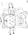
- a charging socket 1 is shown in a perspective view from different directions.
- the charging socket 1 is adapted as a combined charging socket 3, i.e. it has an AC charging socket 5 and a DC charging socket 7.
- the charging socket 1 is used in an electric or hybrid vehicle 9 to connect to a charging plug 11. This is possible, for example, at a publicly accessible charging station 13 or at a private domestic wallbox 15.
- the configuration of the charging socket 1 shown has five heating module shafts 17, which can be seen more clearly in Fig. 2 .
- Each heating module shaft 17 is adapted to receive a heating module 19.
- the heating modules 19 are received in a respective heating module shaft 17, whereas in Fig. 2 the heating modules 19 are shown removed from the respective heating module shaft 17.
- a printed circuit board 20 is shown in Fig. 1 , via which the heating modules 19 can be supplied with electrical power. This circuit board 20 is not shown in Fig. 2 .
- the charging socket 1 has a front side 21 for inserting the charging plug 11 and a rear side 23 facing away from the front side 21.
- the heating module shafts 17 extend from the rear side 23 to the front side 21 of the charging socket 1.
- the heating module shafts 17 open toward the rear side 23.
- the charging socket 1 shown meets the requirements in terms of geometry and connection assignment that are placed on an electric or hybrid vehicle 9. For example, a flattened shape 25 of a contact body 27 (to prevent incorrect plugging in of a charging plug 11), its orientation and positioning with respect to the DC charging socket 7 are specified.
- the contact body 27 has contact receptacles 29 in which, in the assembled state of the charging socket 1 (this state is not shown), electrical contacts (not shown) are received for contacting mating contacts (also not shown) of the charging plug 11.
- the AC charging socket 5 has seven such contact receptacles 29, and the DC charging socket 7 has two. For the sake of clarity, not all contact receptacles 29 are provided with a reference sign.
- the charging socket 1 has a socket wall 31 which surrounds both the contact body 27 of the AC charging socket 5 and the contact body 27 of the DC charging socket 7, while forming an annular gap 33.
- the annular gaps 33 formed around the two contact bodies 27 merge between the AC charging socket 5 and the DC charging socket 7.
- the configuration of the charging socket 1 shown has four thickenings 35 in the socket wall 31. In other configurations, any number of thickenings 35 may be provided.
- the charging socket 1 can be adapted as an AC charging socket 5 only. In this case, the socket wall 31 completely surrounds the AC charging socket 5 and there is no DC charging socket 7. In this case, the socket wall 31 may extend around the contact body 27 in the lower area 37 of the AC charging socket 5 in a preferably circular arc.
- heating module shaft 17 is located in the contact body 27 of the AC charging socket 5, and four heating module shafts 17 extend from the rear side 23 toward the front side 21 in the thickenings 35 of the socket wall 31 of the AC charging socket 5.
- any number of heating module shafts 17 may be provided in any arrangement on the AC charging socket 5, as well as on the DC charging socket 7. The number and positioning shown is purely exemplary.
- the corresponding heating modules 19 can be received in the heating module shafts 17 in any combination, or the heating modules 19 can also be omitted. In other words, as many heating modules 19 can be received in the charging socket 1 (preferably one heating module 19 in each of the corresponding heating module shafts 17) as the charging socket 1 has heating module shafts 17.
- heating module shafts 17 may be left free, i.e., no heating module 19 may be received in these heating module shafts 17.
- no heating module 19 at all may be received in the charging socket 1. In this case, the heating module shafts 17 are empty.
- the same charging socket 1 can be used for each application, which can then be equipped with the appropriate number of heating modules 19 to suit the region in which the electric or hybrid vehicle 9 is to be used.
- a heating power with which the charging socket 1 prevents icing can be set variably.
- the charging socket 1 is therefore variable and versatile and saves manufacturing costs.
- a heating module shaft 17 is arranged in the contact body 27 between two contact receptacles 29. Furthermore, in the configuration shown, four heating module shafts 17 extend from the rear side 23 to the front side 21 in the thickenings 35, that is, in the socket wall 31. All heating module shafts 17 open to the rear side 23, so that a heating module 19 can be inserted into a heating module shaft 17 from the rear side 23 in each case, preferably without play or in a press fit 19a.
- the heating module shafts 17 extend over a shaft depth 39 (see also Fig. 3 - Fig. 5 ) between the rear side 23 and the front side 21 of the charging socket 1.
- This shaft depth 39 is preferably greater than half of a depth 41 between the rear side 23 and the front side 21.
- the shaft depth 39 is indicated.
- the heating module shafts 17 are arranged symmetrically (mirror-symmetrically). In other configurations (not shown), the heating module shafts 17 may be arranged equidistantly on or in the socket wall 31.
- the heating module shafts 17 are closed towards the front 21 by a bottom 43.
- a heating module 19 can be received up to this bottom 43.
- the at least one heating module 19 is received in the respective heating module shaft 17 without play or in a press fit 19a.
- This can be seen, for example, in the sectional views of Fig.3, Fig. 4 and Fig. 5 .
- the sectional views also show that the heating module shaft 19 is adapted to complement the heating module shaft 17. This improves heat transfer from the heating module 19 to the charging socket 1.
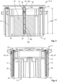
- Figs. 3-5 show various sectional views along the planes A-A, B-B and C-C shown in Fig. 1 .
- Fig. 3 and Fig. 5 show the heating module 19, which is received in the contact body 27.
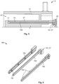
- the heating module 19, which is shown in Fig. 6 in an exploded view, consists of two heating module halves 19b, which are connected to each other via any number of connecting elements 19c (for example pins) and enclose a heating wire 19d.
- the heating wire 19d is accessible only at a contact side 45.
- the heating module 19 is inserted into the heating module shaft 17 via a press fit 19a and extends almost over the entire shaft depth 39.
- the bottom 43 which closes the heating module shaft 17 at the front 21 so that the heating module shaft 17 is only accessible from the rear side 23, can also be seen.
- the connecting elements 19c can be fitted into corresponding mating connecting elements 19f.
- the heating wire 19d has a bend 47 on the contact side 45 of the heating module 19. On the one hand, this ensures the position of the heating wire 19d between the two heating module halves 19b and, on the other hand, a sufficiently large contact area is provided for contacting the printed circuit board 20. This contacting with the printed circuit board 20 is shown schematically in Fig. 5 .
- Fig. 4 two of the four heating modules 19 are shown in sectional view. These are received in the thickenings 35 of the socket wall 31 in a press fit 19a.
- the heating module shaft 17 is bounded in each case by the bottom 43, so that the heating module shafts 17 are accessible only from the rear side 23.
- the heating wires 19d of the heating module 19 shown are also bent over, i.e. provided with a bend 47, in order to make electrical contact with the printed circuit board 20 (not shown, see Fig. 5 ).
Landscapes
- Engineering & Computer Science (AREA)
- Power Engineering (AREA)
- Transportation (AREA)
- Mechanical Engineering (AREA)
- Electric Propulsion And Braking For Vehicles (AREA)
- Details Of Connecting Devices For Male And Female Coupling (AREA)
- Connector Housings Or Holding Contact Members (AREA)
Abstract
Description
- The invention relates to a charging socket of an electric or hybrid vehicle for connection to a charging plug, and a kit for providing the same.
- When charging electric or hybrid vehicles at temperatures below the freezing point, there is a risk of the charging plug becoming iced up and frozen to the charging socket when plugged in after a charging process has been completed. This is due to the fact that during the charging process, heat is generated at the connection between the charging plug and charging socket by the flowing charging current, which melts snow or ice on the vehicle, for example. After the charging process is complete, the charging plug and charging socket cool down and melted water can ice up the charging socket and charging plug so that the charging plug can no longer be pulled out of the charging socket.
- Depending on the region in which the electric or hybrid vehicle is used, such icing can occur with varying frequency, especially in the winter months.
- Thus, it is the object of the present invention to improve existing charging sockets to prevent icing between the charging plug and charging socket or to eliminate existing icing.
- The invention solves this problem for the charging socket mentioned at the beginning in that the charging socket has at least one heating module shaft which is adapted to receive a heating module.
- The invention further solves this problem by using a heating module in a charging socket of an electric or hybrid vehicle, wherein the charging socket has at least one heating module shaft which is adapted to receive the heating module.
- The invention further solves this problem for a kit for providing a heatable charging socket of an electric or hybrid vehicle in that it comprises a charging socket which has a plurality of N heating module shafts and which is arbitrarily equipped with 1 to N heating modules.
- Furthermore, the invention solves this problem for an electric or hybrid vehicle in that the latter is equipped with a charging socket according to the present invention.
- This has the advantage that the charging socket can be heated on the vehicle and thus icing between the charging plug and charging socket can be prevented. It is also possible to use the invention to thaw an iced-up charging socket again and remove the icing. Due to the fact that the heating module is adapted separately, a heating module can be received in the at least one heating module shaft or not, preferably depending on the region in which the electric or hybrid vehicle is to be used. Thus, in warmer regions such as Portugal, for example, the use of a heating module in the heating module shaft of the charging socket can be dispensed with, whereas the charging socket for an electric or hybrid vehicle sold in Norway can be equipped with the at least one heating module.
- A charging socket adapted in such a way also has the advantage that heating of the charging socket is possible independently of the external charging structure used, since the at least one heating module is controlled and operated on the vehicle side. This also prevents icing between the charging plug and charging socket at a public charging station or removes icing when the charging process is complete and the charging plug and charging socket would already have cooled down without the heating module according to the invention. On the vehicle side, this means that the at least one heating module is operated via an on-board energy storage device, preferably the traction battery.
- The invention can be improved by the following further developments, each of which is preferred in itself and can be combined with one another as desired.
- Thus it is particularly preferred if the at least one heating module shaft is cast into the material of the charging socket. The heating module shaft thus forms a shaft-like cavity in a wall of the charging socket.
- The charging socket may have a front side for plugging in the charging plug and a rear side facing away from the front side, wherein the at least one heating module shaft extends from the rear side to the front side of the charging socket. Preferably, the at least one heating module shaft may open toward the rear side.
- Thus, it is possible to insert a heating module into a heating module shaft from the rear side of the charging socket. Preferably, exactly one heating module is inserted into a heating module shaft, or a heating module shaft is adapted to receive exactly one heating module.
- This structure has the advantage that heat can be introduced into the charging socket via the heating module in all directions perpendicular to the extension of the heating module and, for example, not only on one rear side. This is preferred because icing between the charging plug and charging socket occurs at the front of the charging socket.
- The charging socket can have contact receptacles that are adapted to receive electrical contacts for contacting mating contacts of a charging plug. In order to enable a homogeneous heat input, in a preferred configuration the at least one heating module shaft can extend between at least two contact receptacles. This heating module shaft can also extend from the rear side to the front side and can preferably be open towards the rear side and closed towards the front side. This has the advantage that heat can also be introduced into the charging socket between the contact receptacles and not only at its wall.
- In a further preferred configuration, the charging socket can have a socket wall which encloses a contact body receiving contact elements, forming an annular gap, wherein the at least one heating module shaft extends into the socket wall.
- The contact body is to be understood as that part of the charging socket which receives the electrical contacts of the charging socket and forms a plug face. The contact body thereby extends away from the rear side. Spaced apart from the contact body, a self-contained socket wall completely surrounding the contact body can be provided. The annular gap is configured between this socket wall and the contact body. A mating plug can thus preferably be aligned and/or centered and further received in the annular gap. For this purpose, the annular gap and/or the contact body can configure flattened areas which prevent incorrect mating between the charging plug and charging socket.
- Preferably, at least one heating module shaft is provided both in the contact body, here further preferably between at least two contact receptacles, and in the socket wall, so that both the contact body and the socket wall can be heated.
- In a further configuration, the charging socket can have the at least one heating module shaft in an upper third of the charging socket in an assembled state, i.e. when this is installed in an electric or hybrid vehicle. This is preferred because icing occurs increasingly on the upper side of the connection between the charging plug and the charging socket.
- In order to receive the heating module, in a further configuration of the charging socket the socket wall may have at least one thickening in which a heating module shaft is arranged. In other configurations, several thickenings, each having a heating module shaft, may be provided in the socket wall. Preferably, these thickenings are symmetrical, further preferably mirror symmetrical, with respect to an axis extending from top to bottom (with respect to an assembly state of the charging socket). Likewise, the thickenings can be provided rotationally symmetrical and equidistant along the socket wall. Depending on the region in which the electric or hybrid vehicle is to be used, almost any number of thickenings can be provided, each with a heating module shaft. For example, it may be sufficient for some regions if one heating element each is received in a heating module shaft in the upper third of the socket wall and/or in the upper third of the contact body, whereas in a charging socket for an electric or hybrid vehicle for the (for example) Finnish market, it may be preferred if two heating elements are received in one heating module shaft each in the contact body and four or more heating elements are received in four or more heating module shafts each in the socket wall.
- The charging socket can therefore be used in a highly variable and versatile manner without having to manufacture different charging sockets, in other words charging sockets with different geometries, for different markets. Depending on the region of application, the heating module shafts can be left free in any combination or equipped with a heating module.
- Since 2011/2012, it has been possible to use combined charging sockets in electric or hybrid vehicles. In these, the charging socket can be adapted with an AC charging socket and a DC charging socket. In a preferred configuration, the at least one heating module shaft can be arranged on the AC charging socket.
- The DC charging socket is usually used for fast charging of electric or hybrid vehicles, so that the vehicle is used again immediately after the charging process is completed, or the fast charging process is terminated when the vehicle is to be used again, thus it is interrupted at an early stage. In these application cases, icing between the charging plug and charging socket is much less likely than in the case of slower charging via the AC charging socket, which is used to charge electric or hybrid vehicles overnight via so-called wallboxes in private households, for example. Here, the risk of icing is significantly greater, as the charging plug remains in the charging socket after the end of the charging process.
- In particular, the charging socket according to the invention can be adapted as a CCS charging socket (combined charging system) and comply with the IEC 62196 standard, for example.
- Depending on how far a heating module shaft extends from the rear side to the front side, heat can be transferred with varying homogeneity along the direction from the rear side to the front side from the heating element into the charging socket. In one configuration, it is thus preferred if the at least one heating module shaft extends over at least half of the depth between the rear side and the front side of the charging socket. This can ensure more homogeneous heating of the charging socket.
- The depth of the heating module shaft can correspond to an active length of the heating module. The active length is the length over which the heating module can generate and emit heat.
- Since icing can occur in particular at the front of the charging socket, in a particularly preferred configuration a received heating module can have an active area of a first length and a passive area of a second length. In the active area, the heating element generates heat during operation, i.e. when a voltage (preferably controlled and/or regulated by a control unit of the electric vehicle) is applied to it, whereas the heating element in the passive area does not generate any heat during operation. This can be achieved, for example, by the heating element having a higher electrical resistance in the active area than in the passive area, and thus current conduction takes place in the passive area without significant heat loss (this heat loss is used in the active area to heat the charging socket). This can be used in particular to heat an area of the charging socket facing the front side, since icing is more likely to occur at this front side than at the rear side, i.e. in an area of the charging socket facing the vehicle or offset into it.
- This can have the further advantage that heat only has to be generated at those points of the charging socket that may be affected by icing. This avoids unnecessary energy input in the form of heat in areas of the charging socket that are not affected by icing anyway. This saves electrical energy taken from the energy storage (e.g. from the traction battery) of the electric or hybrid vehicle.
- In a preferred configuration of the charging socket according to the invention, a plurality of heating module shafts is provided in the contact body and/or in the socket wall, wherein the heating module shafts open towards the rear side. The heating module shafts are preferably symmetrical, and further preferably mirror-symmetrical, with respect to an axis extending from top to bottom (with respect to the assembly state of the charging socket). Likewise, the heating module shafts can be rotationally symmetrical and equidistantly, i.e. equally distributed, arranged along a circumferential direction. Depending on the region in which the electric or hybrid vehicle is to be used, almost any number of heating module shafts can be equipped or fitted with one heating module each.
- In a further preferred configuration, the at least one heating module shaft may have a bottom closing the at least one heating module shaft to the front side.
- The heating module shaft can thus be closed at the front side. At the front side, thus at the bottom of the heating module shaft, the cavity extending in the wall of the charging socket (of the contact carrier) can thus end and two opposite walls of the heating module shaft of the contact carrier can unite to form one wall of the charging socket (of the contact carrier).
- A closed heating module shaft can be protected against the entry of foreign bodies and/or water because it is not accessible from outside the electric or hybrid vehicle when the charging socket is installed. If no heating module is inserted in a heating module shaft, this can, for example, be inserted subsequently by appropriately trained service personnel in the corresponding heating module shaft, which was previously inaccessible and thus kept free of contamination.
- In order to enable good heat transfer between the heating module and the charging socket, i.e. between the heating module and an inner wall of the heating module shaft, in a further preferred configuration of the charging socket the heating module can be received in the respective heating module shaft without play or in a press fit. Preferably, the heating module is press-fitted into the respective heating module shaft. This enables good heat transfer from the heating module to the socket wall or contact body.
- Particularly preferably, the heating module is adapted to complement the heating module shaft. This has the advantage that heat transfer is not impaired by air gaps. Ideally, the material of the heating module nestles against the material of an inner wall of the heating module shaft, so that heat transfer can take place by heat conduction. However, as soon as an air gap occurs, heat transfer is no longer performed exclusively by heat conduction, but also by heat radiation. However, this process conducts the heat generated by the heating module to the charging socket less effectively than heat conduction (an air gap has an insulating rather than a transferring effect; cf. insulating double-glazed windows).
- In a preferred configuration, the above-mentioned kit according to the invention comprises identical or different heating modules. For example, a heating module with greater heating power can be received in the corresponding heating module shaft on an upper side of the charging socket than on a lower side of the charging socket. This takes into account a higher probability of icing on an upper side of the charging socket and can counteract this.
- The heating module may include a heating resistor received in a housing. The heating resistor may be received in a two-part housing or in a housing produced by overmolding. In particular, the heating resistor may have electrical connections, wherein the electrical connections preferably face the rear side of the charging socket when the heating module is received in the respective heating module shaft. The at least one heating module can thus only be accessible and electrically contactable from the rear side. On the rear side, the charging socket can have a printed circuit board via which the heating element or elements can be controlled and contacted. For example, bent sections of the heating resistor or contacting means such as contact springs or contact pills attached to the heating resistor are suitable for this.
- In the following, the invention is explained by way of example on the basis of embodiments with reference to the enclosed drawings. For the sake of simplicity, the same reference signs are always used for elements that correspond to each other in terms of function and/or structure.
- In accordance with the above embodiments, a feature may be omitted in any of the following embodiments if its technical effect is not important in a particular application. Further, according to the above embodiments, features the technical effect of which is important in a particular application may be added.
- It is shown by:
- Fig. 1
- a schematic representation of the charging socket according to the invention in a perspective front view;
- Fig. 2
- a schematic exploded view of the charging socket according to the invention in a perspective rear view;
- Fig. 3
- a sectional view along the plane A-A shown in
Fig. 1 ; - Fig. 4
- a perspective sectional view along the plane B-B shown in
Fig. 1 ; - Fig. 5
- an enlarged sectional view along the plane C-C shown in
Fig. 1 ; and - Fig. 6
- an exploded view of a configuration of the heating module according to the invention.
- In
Fig. 1 andFig. 2 , a chargingsocket 1 is shown in a perspective view from different directions. The chargingsocket 1 is adapted as a combined charging socket 3, i.e. it has anAC charging socket 5 and a DC charging socket 7. - The charging
socket 1 is used in an electric orhybrid vehicle 9 to connect to a chargingplug 11. This is possible, for example, at a publicly accessible chargingstation 13 or at a privatedomestic wallbox 15. - The configuration of the charging
socket 1 shown has fiveheating module shafts 17, which can be seen more clearly inFig. 2 . Eachheating module shaft 17 is adapted to receive aheating module 19. InFig. 1 , theheating modules 19 are received in a respectiveheating module shaft 17, whereas inFig. 2 theheating modules 19 are shown removed from the respectiveheating module shaft 17. Furthermore, a printedcircuit board 20 is shown inFig. 1 , via which theheating modules 19 can be supplied with electrical power. Thiscircuit board 20 is not shown inFig. 2 . - The following explanations refer to both
Fig. 1 andFig. 2 . - The charging
socket 1 has afront side 21 for inserting the chargingplug 11 and arear side 23 facing away from thefront side 21. - In the configuration of the charging
socket 1 shown, theheating module shafts 17 extend from therear side 23 to thefront side 21 of the chargingsocket 1. - As can be seen in
Fig. 2 , theheating module shafts 17 open toward therear side 23. - The charging
socket 1 shown meets the requirements in terms of geometry and connection assignment that are placed on an electric orhybrid vehicle 9. For example, a flattenedshape 25 of a contact body 27 (to prevent incorrect plugging in of a charging plug 11), its orientation and positioning with respect to the DC charging socket 7 are specified. - The
contact body 27 hascontact receptacles 29 in which, in the assembled state of the charging socket 1 (this state is not shown), electrical contacts (not shown) are received for contacting mating contacts (also not shown) of the chargingplug 11. TheAC charging socket 5 has sevensuch contact receptacles 29, and the DC charging socket 7 has two. For the sake of clarity, not allcontact receptacles 29 are provided with a reference sign. - The charging
socket 1 has asocket wall 31 which surrounds both thecontact body 27 of theAC charging socket 5 and thecontact body 27 of the DC charging socket 7, while forming anannular gap 33. Theannular gaps 33 formed around the twocontact bodies 27 merge between theAC charging socket 5 and the DC charging socket 7. - The configuration of the charging
socket 1 shown has fourthickenings 35 in thesocket wall 31. In other configurations, any number ofthickenings 35 may be provided. Likewise, the chargingsocket 1 can be adapted as anAC charging socket 5 only. In this case, thesocket wall 31 completely surrounds theAC charging socket 5 and there is no DC charging socket 7. In this case, thesocket wall 31 may extend around thecontact body 27 in thelower area 37 of theAC charging socket 5 in a preferably circular arc. - With reference to
Fig. 1 andFig. 2 , it is shown that in the configuration of the chargingsocket 1 shown in the Figures, oneheating module shaft 17 is located in thecontact body 27 of theAC charging socket 5, and fourheating module shafts 17 extend from therear side 23 toward thefront side 21 in thethickenings 35 of thesocket wall 31 of theAC charging socket 5. In other configurations (not shown) of the chargingsocket 1, any number ofheating module shafts 17 may be provided in any arrangement on theAC charging socket 5, as well as on the DC charging socket 7. The number and positioning shown is purely exemplary. - Likewise, the
corresponding heating modules 19 can be received in theheating module shafts 17 in any combination, or theheating modules 19 can also be omitted. In other words, asmany heating modules 19 can be received in the charging socket 1 (preferably oneheating module 19 in each of the corresponding heating module shafts 17) as the chargingsocket 1 hasheating module shafts 17. - On the other hand, however, some
heating module shafts 17 may be left free, i.e., noheating module 19 may be received in theseheating module shafts 17. In particular, in warmer regions where the electric orhybrid vehicle 9 is to be used, noheating module 19 at all may be received in the chargingsocket 1. In this case, theheating module shafts 17 are empty. - However, the
same charging socket 1 can be used for each application, which can then be equipped with the appropriate number ofheating modules 19 to suit the region in which the electric orhybrid vehicle 9 is to be used. Thus, a heating power with which the chargingsocket 1 prevents icing can be set variably. The chargingsocket 1 is therefore variable and versatile and saves manufacturing costs. - In the configuration shown, a
heating module shaft 17 is arranged in thecontact body 27 between twocontact receptacles 29. Furthermore, in the configuration shown, fourheating module shafts 17 extend from therear side 23 to thefront side 21 in thethickenings 35, that is, in thesocket wall 31. Allheating module shafts 17 open to therear side 23, so that aheating module 19 can be inserted into aheating module shaft 17 from therear side 23 in each case, preferably without play or in a press fit 19a. - The
heating module shafts 17 extend over a shaft depth 39 (see alsoFig. 3 - Fig. 5 ) between therear side 23 and thefront side 21 of the chargingsocket 1. Thisshaft depth 39 is preferably greater than half of adepth 41 between therear side 23 and thefront side 21. InFig. 2 , theshaft depth 39 is indicated. - In the
socket wall 31, theheating module shafts 17 are arranged symmetrically (mirror-symmetrically). In other configurations (not shown), theheating module shafts 17 may be arranged equidistantly on or in thesocket wall 31. - The
heating module shafts 17 are closed towards the front 21 by a bottom 43. Aheating module 19 can be received up to this bottom 43. Preferably, the at least oneheating module 19 is received in the respectiveheating module shaft 17 without play or in a press fit 19a. This can be seen, for example, in the sectional views ofFig.3, Fig. 4 andFig. 5 . The sectional views also show that theheating module shaft 19 is adapted to complement theheating module shaft 17. This improves heat transfer from theheating module 19 to the chargingsocket 1. -
Figs. 3-5 show various sectional views along the planes A-A, B-B and C-C shown inFig. 1 . -
Fig. 3 andFig. 5 show theheating module 19, which is received in thecontact body 27. Theheating module 19, which is shown inFig. 6 in an exploded view, consists of two heating module halves 19b, which are connected to each other via any number of connectingelements 19c (for example pins) and enclose aheating wire 19d. Theheating wire 19d is accessible only at acontact side 45. - The
heating module 19 is inserted into theheating module shaft 17 via a press fit 19a and extends almost over theentire shaft depth 39. The bottom 43, which closes theheating module shaft 17 at the front 21 so that theheating module shaft 17 is only accessible from therear side 23, can also be seen. - In the exploded view of
Fig. 6 , it is further shown that the connectingelements 19c can be fitted into correspondingmating connecting elements 19f. Furthermore, it is shown that theheating wire 19d has a bend 47 on thecontact side 45 of theheating module 19. On the one hand, this ensures the position of theheating wire 19d between the two heating module halves 19b and, on the other hand, a sufficiently large contact area is provided for contacting the printedcircuit board 20. This contacting with the printedcircuit board 20 is shown schematically inFig. 5 . - In
Fig. 4 , two of the fourheating modules 19 are shown in sectional view. These are received in thethickenings 35 of thesocket wall 31 in a press fit 19a. Theheating module shaft 17 is bounded in each case by the bottom 43, so that theheating module shafts 17 are accessible only from therear side 23. At this rear side, theheating wires 19d of theheating module 19 shown are also bent over, i.e. provided with a bend 47, in order to make electrical contact with the printed circuit board 20 (not shown, seeFig. 5 ). -
- 1
- charging socket
- 3
- combined charging socket
- 5
- AC charging socket
- 7
- DC charging socket
- 9
- electric or hybrid vehicle
- 11
- charging plug
- 13
- public charging station
- 15
- private wall box
- 17
- heating module shaft
- 19
- heating module
- 19a
- press fit
- 19b
- heating module half
- 19c
- connection element
- 19d
- heating wire
- 20
- printed circuit board
- 21
- front side
- 23
- rear side
- 25
- flattened shape
- 27
- contact body
- 29
- contact receptacle
- 31
- socket wall
- 33
- annular gap
- 35
- thickening
- 37
- lower area
- 39
- shaft depth
- 41
- depth between the rear side and the front side
- 43
- bottom
- 45
- contact side
- 47
- bend of the heating wire
- A-A
- plane
- B-B
- plane
- C-C
- plane
Claims (15)
- Charging socket (1) of an electric or hybrid vehicle (9) for connection to a charging plug (11), wherein the charging socket (1) has at least one heating module shaft (17) which is adapted to receive a heating module (19).
- Charging socket (1) according to claim 1, wherein the charging socket (1) has a front side (21) for plugging in the charging plug (11) and a rear side (23) facing away from the front side (21), wherein the at least one heating module shaft (17) extends from the rear side (23) to the front side (21) of the charging socket (1).
- Charging socket (1) according to claim 2, wherein the at least one heating module shaft (17) opens towards the rear side (23).
- Charging socket (1) according to one of claims 1 to 3, wherein the charging socket (1) has contact receptacles (29) which are adapted to receive electrical contacts for contacting mating contacts of a charging plug (11), and wherein the at least one heating module shaft (17) extends between at least two contact receptacles (29).
- Charging socket (1) according to one of claims 1 to 4, wherein the charging socket (1) has a socket wall (31) which, while forming an annular gap (33), encloses a contact body (27) receiving contact elements, wherein the at least one heating module shaft (17) extends into the socket wall (31).
- Charging socket (1) according to claim 5, wherein the socket wall (31) has at least one thickening (35) in which a heating module shaft (17) is arranged.
- Charging socket (1) according to one of claims 1 to 4, wherein the charging socket (1) is adapted with an AC charging socket (5) and a DC charging socket (7), and wherein the at least one heating module shaft (17) is arranged at the AC charging socket (5).
- Charging socket (1) according to one of claims 2 to 6, wherein the at least one heating module shaft (17) extends over at least half of the depth (41) between the rear side and the front side of the charging socket (1).
- Charging socket (1) according to one of claims 5 to 8, wherein a plurality of heating module shafts (17) is provided in the contact body (27) and/or in the socket wall (31), wherein the heating module shafts (17) open towards the rear side (23).
- Charging socket (1) according to one of claims 2 to 8, wherein the at least one heating module shaft (17) has, towards the front side (21), a bottom (43) closing the at least one heating module shaft (17).
- Charging socket (1) according to one of claims 1 to 10, wherein the heating module (19) is received in the respective heating module shaft (17) without play or in a press fit (19a).
- Charging socket (1) according to one of claims 1 to 11, wherein the heating module (19) is adapted to complement the heating module shaft (17).
- Use of a heating module (19) in a charging socket (1) of an electric or hybrid vehicle (9), wherein the charging socket (1) has at least one heating module shaft (17) which is adapted to receive the heating module (19).
- Kit for providing a heatable charging socket (1) of an electric or hybrid vehicle (9), comprising a charging socket (1) having a plurality of N heating module shafts (17) arbitrarily equipped with 1 to N heating modules (19).
- Electric or hybrid vehicle (9) with a charging socket (1) according to one of claims 1 to 12.
Applications Claiming Priority (1)
| Application Number | Priority Date | Filing Date | Title |
|---|---|---|---|
| DE102022118827.2A DE102022118827A1 (en) | 2022-07-27 | 2022-07-27 | Heated charging socket |
Publications (2)
| Publication Number | Publication Date |
|---|---|
| EP4312324A1 true EP4312324A1 (en) | 2024-01-31 |
| EP4312324B1 EP4312324B1 (en) | 2026-06-24 |
Family
ID=87474135
Family Applications (1)
| Application Number | Title | Priority Date | Filing Date |
|---|---|---|---|
| EP23187409.0A Active EP4312324B1 (en) | 2022-07-27 | 2023-07-25 | Heatable charging socket |
Country Status (6)
| Country | Link |
|---|---|
| US (1) | US20240034162A1 (en) |
| EP (1) | EP4312324B1 (en) |
| JP (1) | JP7618744B2 (en) |
| KR (1) | KR102884560B1 (en) |
| CN (1) | CN117477271A (en) |
| DE (1) | DE102022118827A1 (en) |
Families Citing this family (5)
| Publication number | Priority date | Publication date | Assignee | Title |
|---|---|---|---|---|
| US20240075839A1 (en) * | 2022-09-07 | 2024-03-07 | GM Global Technology Operations LLC | Heated ev charge coupler |
| WO2025170379A1 (en) * | 2024-02-07 | 2025-08-14 | 엘지이노텍 주식회사 | Vehicle charging port and vehicle charging device including same |
| DE102024124047A1 (en) | 2024-08-22 | 2026-02-26 | Kiekert Aktiengesellschaft | Electric charging device of a motor vehicle |
| DE102024133796A1 (en) | 2024-11-19 | 2026-05-21 | Kiekert Aktiengesellschaft | Heating for charging port and charging plug locking mechanism |
| CN119297675A (en) * | 2024-12-12 | 2025-01-10 | 泰科电子(上海)有限公司 | Charging station heater, lead frame assembly and charging station |
Citations (3)
| Publication number | Priority date | Publication date | Assignee | Title |
|---|---|---|---|---|
| CN110247246A (en) * | 2019-07-25 | 2019-09-17 | 南京康尼新能源汽车零部件有限公司 | Electric car charging socket and its single seal assemble method |
| US20210078419A1 (en) * | 2019-09-16 | 2021-03-18 | Te Connectivity Corporation | Temperature sensor for terminal of charging inlet assembly |
| CN212950215U (en) * | 2020-08-19 | 2021-04-13 | 北京福田戴姆勒汽车有限公司 | Charging socket for electric vehicle and charging pile with same |
Family Cites Families (9)
| Publication number | Priority date | Publication date | Assignee | Title |
|---|---|---|---|---|
| JPH1174032A (en) * | 1997-08-30 | 1999-03-16 | Horiba Ltd | Connector with condensation prevention function |
| CN204304097U (en) * | 2015-01-14 | 2015-04-29 | 成都柯恩斯科技有限公司 | A kind of water proof type charging electric vehicle socket |
| DE102016122009A1 (en) * | 2016-11-16 | 2018-05-17 | Dr. Ing. H.C. F. Porsche Aktiengesellschaft | Charging device for an electrically driven vehicle |
| DE102017004295A1 (en) * | 2017-05-04 | 2017-11-02 | Daimler Ag | Trough element for a motor vehicle |
| DE102017112390A1 (en) * | 2017-06-06 | 2018-12-06 | Dr. Ing. H.C. F. Porsche Aktiengesellschaft | Charging socket for an electrically driven vehicle |
| US20190217713A1 (en) * | 2018-01-16 | 2019-07-18 | Ford Global Technologies, Llc | Charging port heater |
| FR3079784B1 (en) * | 2018-04-06 | 2021-01-15 | Psa Automobiles Sa | ELECTRIC OR HYBRID MOTOR VEHICLE BATTERY RECHARGE SOCKET WITH HEATING RESISTOR |
| CN209738837U (en) * | 2019-02-27 | 2019-12-06 | 北京长城华冠汽车科技股份有限公司 | An electrical connection device, charging equipment and vehicle charging system |
| DE102021118380A1 (en) * | 2021-07-15 | 2023-01-19 | Arte Reverse Engineering GbR (vertretungsberechtigter Gesellschafter Heiko Lantzsch, 98617 Vachdorf) | Novel plug and socket for charging electrically powered motor vehicles |
-
2022
- 2022-07-27 DE DE102022118827.2A patent/DE102022118827A1/en active Pending
-
2023
- 2023-07-24 JP JP2023119772A patent/JP7618744B2/en active Active
- 2023-07-24 CN CN202310912368.4A patent/CN117477271A/en active Pending
- 2023-07-25 EP EP23187409.0A patent/EP4312324B1/en active Active
- 2023-07-26 KR KR1020230097405A patent/KR102884560B1/en active Active
- 2023-07-27 US US18/360,044 patent/US20240034162A1/en active Pending
Patent Citations (3)
| Publication number | Priority date | Publication date | Assignee | Title |
|---|---|---|---|---|
| CN110247246A (en) * | 2019-07-25 | 2019-09-17 | 南京康尼新能源汽车零部件有限公司 | Electric car charging socket and its single seal assemble method |
| US20210078419A1 (en) * | 2019-09-16 | 2021-03-18 | Te Connectivity Corporation | Temperature sensor for terminal of charging inlet assembly |
| CN212950215U (en) * | 2020-08-19 | 2021-04-13 | 北京福田戴姆勒汽车有限公司 | Charging socket for electric vehicle and charging pile with same |
Also Published As
| Publication number | Publication date |
|---|---|
| JP7618744B2 (en) | 2025-01-21 |
| KR20240015597A (en) | 2024-02-05 |
| JP2024019057A (en) | 2024-02-08 |
| EP4312324B1 (en) | 2026-06-24 |
| US20240034162A1 (en) | 2024-02-01 |
| DE102022118827A1 (en) | 2024-02-01 |
| KR102884560B1 (en) | 2025-11-17 |
| CN117477271A (en) | 2024-01-30 |
Similar Documents
| Publication | Publication Date | Title |
|---|---|---|
| KR102884560B1 (en) | Heatable charging socket | |
| JP7341262B2 (en) | High current module in charging plug-in connector | |
| CN112615216B (en) | Power connector system | |
| ES2376387T3 (en) | ELECTRICAL HEATING DEVICE. | |
| CN109004464B (en) | Charging sockets for electric powered vehicles | |
| CN110341513B (en) | Charging coupling with cooling device, charging cable and motor vehicle | |
| US10230081B2 (en) | Voltage-protected producible motor vehicle battery | |
| KR102084387B1 (en) | Battery assembly | |
| JP5791084B2 (en) | Interlock circuit connector assembly | |
| JP6401697B2 (en) | Safety system for high current applications | |
| EP3381092B1 (en) | Electrical module | |
| US20090321129A1 (en) | Electrical Junction Box | |
| US9614197B2 (en) | Onboard battery | |
| US10665911B2 (en) | Battery module | |
| KR102825245B1 (en) | Electrical high-current connector | |
| CN107078261A (en) | Lead frame with the battery module for sacrificing cross tie part | |
| CN105321637A (en) | Thermistor assembly including elastomeric body | |
| CN104953076A (en) | Integrated high voltage service disconnect | |
| US20230119572A1 (en) | Plug contact | |
| US20170028860A1 (en) | Electrical distributor arrangement | |
| CN116710315A (en) | Charging inlet | |
| CN105185942B (en) | Slot cover for battery array | |
| CN102461356B (en) | Electric power transfer device for an automobile, and electric or partially electric vehicle provided with such a device | |
| EP3771592B1 (en) | Passive device for cooling electrical cable | |
| CN108667109A (en) | Power cut-off device and battery system |
Legal Events
| Date | Code | Title | Description |
|---|---|---|---|
| PUAI | Public reference made under article 153(3) epc to a published international application that has entered the european phase |
Free format text: ORIGINAL CODE: 0009012 |
|
| STAA | Information on the status of an ep patent application or granted ep patent |
Free format text: STATUS: REQUEST FOR EXAMINATION WAS MADE |
|
| 17P | Request for examination filed |
Effective date: 20230725 |
|
| AK | Designated contracting states |
Kind code of ref document: A1 Designated state(s): AL AT BE BG CH CY CZ DE DK EE ES FI FR GB GR HR HU IE IS IT LI LT LU LV MC ME MK MT NL NO PL PT RO RS SE SI SK SM TR |
|
| RBV | Designated contracting states (corrected) |
Designated state(s): AL AT BE BG CH CY CZ DE DK EE ES FI FR GB GR HR HU IE IS IT LI LT LU LV MC ME MK MT NL NO PL PT RO RS SE SI SK SM TR |
|
| GRAP | Despatch of communication of intention to grant a patent |
Free format text: ORIGINAL CODE: EPIDOSNIGR1 |
|
| STAA | Information on the status of an ep patent application or granted ep patent |
Free format text: STATUS: GRANT OF PATENT IS INTENDED |
|
| RIC1 | Information provided on ipc code assigned before grant |
Ipc: H01R 13/66 20060101AFI20260114BHEP Ipc: B60L 53/16 20190101ALI20260114BHEP Ipc: B60L 53/302 20190101ALI20260114BHEP Ipc: H05B 3/06 20060101ALI20260114BHEP |
|
| INTG | Intention to grant announced |
Effective date: 20260129 |
|
| GRAS | Grant fee paid |
Free format text: ORIGINAL CODE: EPIDOSNIGR3 |
|
| GRAA | (expected) grant |
Free format text: ORIGINAL CODE: 0009210 |
|
| STAA | Information on the status of an ep patent application or granted ep patent |
Free format text: STATUS: THE PATENT HAS BEEN GRANTED |
|
| AK | Designated contracting states |
Kind code of ref document: B1 Designated state(s): AL AT BE BG CH CY CZ DE DK EE ES FI FR GB GR HR HU IE IS IT LI LT LU LV MC ME MK MT NL NO PL PT RO RS SE SI SK SM TR |
|
| REG | Reference to a national code |
Ref country code: CH Ref legal event code: F10 Free format text: ST27 STATUS EVENT CODE: U-0-0-F10-F00 (AS PROVIDED BY THE NATIONAL OFFICE) Effective date: 20260624 Ref country code: GB Ref legal event code: FG4D |
|
| REG | Reference to a national code |
Ref country code: IE Ref legal event code: FG4D |
|
| REG | Reference to a national code |
Ref country code: DE Ref legal event code: R096 Ref document number: 602023018791 Country of ref document: DE |