EP4312312A1 - Wire assembly with welded contact - Google Patents
Wire assembly with welded contact Download PDFInfo
- Publication number
- EP4312312A1 EP4312312A1 EP22186619.7A EP22186619A EP4312312A1 EP 4312312 A1 EP4312312 A1 EP 4312312A1 EP 22186619 A EP22186619 A EP 22186619A EP 4312312 A1 EP4312312 A1 EP 4312312A1
- Authority
- EP
- European Patent Office
- Prior art keywords
- contact
- assembly
- inner conductor
- welded
- conductor
- Prior art date
- Legal status (The legal status is an assumption and is not a legal conclusion. Google has not performed a legal analysis and makes no representation as to the accuracy of the status listed.)
- Pending
Links
Images




Classifications
-
- H—ELECTRICITY
- H01—ELECTRIC ELEMENTS
- H01R—ELECTRICALLY-CONDUCTIVE CONNECTIONS; STRUCTURAL ASSOCIATIONS OF A PLURALITY OF MUTUALLY-INSULATED ELECTRICAL CONNECTING ELEMENTS; COUPLING DEVICES; CURRENT COLLECTORS
- H01R4/00—Electrically-conductive connections between two or more conductive members in direct contact, i.e. touching one another; Means for effecting or maintaining such contact; Electrically-conductive connections having two or more spaced connecting locations for conductors and using contact members penetrating insulation
- H01R4/02—Soldered or welded connections
- H01R4/023—Soldered or welded connections between cables or wires and terminals
-
- H—ELECTRICITY
- H01—ELECTRIC ELEMENTS
- H01R—ELECTRICALLY-CONDUCTIVE CONNECTIONS; STRUCTURAL ASSOCIATIONS OF A PLURALITY OF MUTUALLY-INSULATED ELECTRICAL CONNECTING ELEMENTS; COUPLING DEVICES; CURRENT COLLECTORS
- H01R24/00—Two-part coupling devices, or either of their cooperating parts, characterised by their overall structure
- H01R24/38—Two-part coupling devices, or either of their cooperating parts, characterised by their overall structure having concentrically or coaxially arranged contacts
- H01R24/40—Two-part coupling devices, or either of their cooperating parts, characterised by their overall structure having concentrically or coaxially arranged contacts specially adapted for high frequency
- H01R24/54—Intermediate parts, e.g. adapters, splitters or elbows
- H01R24/545—Elbows
-
- H—ELECTRICITY
- H01—ELECTRIC ELEMENTS
- H01R—ELECTRICALLY-CONDUCTIVE CONNECTIONS; STRUCTURAL ASSOCIATIONS OF A PLURALITY OF MUTUALLY-INSULATED ELECTRICAL CONNECTING ELEMENTS; COUPLING DEVICES; CURRENT COLLECTORS
- H01R4/00—Electrically-conductive connections between two or more conductive members in direct contact, i.e. touching one another; Means for effecting or maintaining such contact; Electrically-conductive connections having two or more spaced connecting locations for conductors and using contact members penetrating insulation
- H01R4/02—Soldered or welded connections
- H01R4/029—Welded connections
-
- H—ELECTRICITY
- H01—ELECTRIC ELEMENTS
- H01R—ELECTRICALLY-CONDUCTIVE CONNECTIONS; STRUCTURAL ASSOCIATIONS OF A PLURALITY OF MUTUALLY-INSULATED ELECTRICAL CONNECTING ELEMENTS; COUPLING DEVICES; CURRENT COLLECTORS
- H01R13/00—Details of coupling devices of the kinds covered by groups H01R12/70 or H01R24/00 - H01R33/00
- H01R13/02—Contact members
- H01R13/025—Contact members formed by the conductors of a cable end
-
- H—ELECTRICITY
- H01—ELECTRIC ELEMENTS
- H01R—ELECTRICALLY-CONDUCTIVE CONNECTIONS; STRUCTURAL ASSOCIATIONS OF A PLURALITY OF MUTUALLY-INSULATED ELECTRICAL CONNECTING ELEMENTS; COUPLING DEVICES; CURRENT COLLECTORS
- H01R2103/00—Two poles
-
- H—ELECTRICITY
- H01—ELECTRIC ELEMENTS
- H01R—ELECTRICALLY-CONDUCTIVE CONNECTIONS; STRUCTURAL ASSOCIATIONS OF A PLURALITY OF MUTUALLY-INSULATED ELECTRICAL CONNECTING ELEMENTS; COUPLING DEVICES; CURRENT COLLECTORS
- H01R9/00—Structural associations of a plurality of mutually-insulated electrical connecting elements, e.g. terminal strips or terminal blocks; Terminals or binding posts mounted upon a base or in a case; Bases therefor
- H01R9/03—Connectors arranged to contact a plurality of the conductors of a multiconductor cable, e.g. tapping connections
- H01R9/05—Connectors arranged to contact a plurality of the conductors of a multiconductor cable, e.g. tapping connections for coaxial cables
- H01R9/0518—Connection to outer conductor by crimping or by crimping ferrule
Definitions
- the present disclosure is directed to a wire assembly and in particular to a wire assembly that includes a contact welded to an inner conductor of the wire assembly.
- Wire connector assemblies - for example, coaxial cable connector assemblies - have been used for numerous automotive applications, such as navigation systems, infotainment systems, air bag systems, and other data transmission systems.
- a typical wire may include an inner conductor surrounded by a jacket.
- a typical coaxial cable includes an outer shield conductor, an inner center conductor, a dielectric, and an insulation jacket. The outer conductor and the inner conductor of the coaxial cable often electrically interface with a mating coaxial cable through a coaxial connector assembly.
- Radio Frequency (RF) connectors most often referred to simply as RF connectors are often used to connect coaxial cables while providing a certain degree of shielding. The use of RF connectors for coaxial cable has greatly increased in automotive applications as devices requiring high speed data communication continue to proliferate.
- contacts connected to the inner conductor of a coaxial cable are mechanically adhered to the cable via crimping or soldering of the inner conductor to the contact.
- a contact may comprise several wings that are wrapped around the inner conductor and crimped onto the conductor to ensure an electrical and mechanical connection between the contact and the inner conductor.
- the contact may include a pin or terminal configured to interface with a terminal assembly to provide electrical contact between the inner conductor of the coaxial cable and the terminal assembly.
- the contacts are often non-rigid and compliant and require orientation with respect to the coaxial cable during the crimping (or soldering) operation. It would be beneficial to develop a contact that does not utilize crimping and/or soldering between the contact and the inner conductor of the coaxial cable while being capable of interfacing with a terminal assembly.
- a wire assembly includes an insulated wire and a contact.
- the cable includes at least an inner conductor and an insulating jacket surrounding the inner conductor, wherein a tip of the inner conductor is exposed at a first end.
- the contact is welded to the tip of the inner conductor at the first end.
- a coaxial connection assembly includes a coaxial cable and a terminal assembly.
- the coaxial cable includes an inner conductor, a dielectric insulator, an outer conductor and a jacket, wherein the outer conductor and the jacket are stripped from a first end, wherein at least a tip of the inner conductor is exposed at the first end.
- a contact is welded to the tip of the inner conductor at the first end.
- the outer terminal assembly includes a first opening for receiving the first end of the coaxial cable assembly, wherein the outer terminal includes a first insulator located within the outer terminal assembly configured to receive the welded contact of the coaxial cable assembly.
- Figure 1A is a side view of a coaxial cable assembly and welded contact according to some embodiments
- Figure 1B is a side view of a center core of the coaxial cable assembly welded to the contact according to some embodiments.
- Figure 2A is a side view of an outer terminal assembly and a coaxial cable assembly having a welded contact according to some embodiments
- Figure 2B is a side view of the outer terminal assembly mated with the coaxial cable assembly and a magnified cross-sectional view illustrating seating of the welded contact within the outer terminal assembly according to some embodiments
- Figure 2C is a side view of the outer terminal assembly mated with the coaxial cable assembly and a magnified cross-sectional view illustrating the terminal associated with the outer terminal assembly being moved from a stage position to a seated position in contact with the welded contact according to some embodiments
- Figure 2D is a side view illustrating crimping of coaxial cable assembly to the outer terminal assembly according to some embodiments.
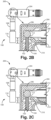
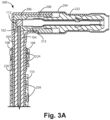
- Figure 3A is a cross-sectional view of the outer terminal assembly that illustrates a a terminal associated with the outer terminal assembly in a stage position according to some embodiments; and Figure 3B is a cross-sectional view of the outer terminal assembly that illustrates the terminal associated with the outer terminal assembly in a seated position in contact with the welded contact according to some embodiments.
- the present disclosure is directed to a wire assembly and in particular to a wire assembly that includes a contact welded to an inner conductor of the wire assembly.
- a wire assembly includes at least an inner conductor surrounded by an insulating jacket.
- a first end of the wire is cut to expose a tip portion of the inner conductor, wherein the contact is welded to the tip portion of the inner conductor.
- the tip portion is non-oriented, meaning that the contact does not need to be oriented during welding of the contact to the tip portion of the inner conductor.
- the wire assembly is a coaxial wire assembly.
- FIG. 1A and 1B are side views of a coaxial cable assembly 100 and welded contact 112 according to some embodiment.
- coaxial cable assembly 100 includes an inner conductor 102, dielectric insulator 104, foil shield 106, outer conductor 108 and jacket 110.
- Contact 112 is a conductive contact configured to be welded to the inner conductor 102.
- a coaxial cable assembly is shown in Figure 1A and 1B , the discussion is applicable to a simple wire assembly that includes only an inner conductor and an insulating jacket.
- the embodiment shown in Figures 1A and 1B illustrate a coaxial cable assembly having, for example, a foil shield. In some embodiments, a coaxial cable assembly does not require a separate foil shield.
- a portion of dielectric insulator 104 (as well a portion of the foil shield 106, if included, outer conductor 108, and jacket 110) is cut or stripped to expose a tip portion 103 of the inner conductor 102.
- the tip portion is in a plane substantially perpendicular to the longitudinal axis of the wire or coaxial cable.
- only the tip portion 103 of the inner conductor 102 is exposed (i.e., no circumferential surface of the inner conductor 102).
- Contact 112 is then welded to the tip portion 103 of the inner conductor 102, with no portion of the contact 112 contacting the outer circumference of the inner conductor 102.
- a portion of the dielectric insulator 104 is stripped from the inner conductor, exposing a length of the inner conductor 102.
- the length of dielectric insulator 104 stripped from the inner conductor 102 is represented by the length d1 as shown in Figure 1A .
- Contact 112 is welded to the tip portion 103 of the inner conductor 102 as shown in Figure 1B . In some embodiments, the contact 112 again is only in contact with the tip portion 103 of the inner conductor 102, although at least a portion of the outer circumference of the inner conductor 102 may be exposed.
- the embodiment shown in Figures 1A and 1B allows for a very short length of dielectric insulator 104 to be stripped.
- the length d1 is equal to or less than 1.0 millimeters (mm). In some embodiments, the length d1 is equal to or less than 0.7 mm. In some embodiments, the dielectric insulator 104 and inner conductor 102 are cut to the same length, which results in the length d1 being equal to zero.
- the distance d1 between the end or stripped portion of the dielectric insulator 104 and the end of the inner conductor 102 is based on the geometry of the terminal assembly with which the coaxial cable assembly 100 interacts. Decreasing the length d1 improves the performance of the coaxial connection. In particular, impedance mismatches introduced by the relatively long interface associated with the inner conductor and a crimped contact are reduced as a result of the relatively short interface made possible by the welded contact 112. The reduction in impedance mismatches improves the RF performance of the interface between the coaxial assembly and the outer terminal assembly (shown in Figures 2A-2D ).
- the welded contact 112 comprises a material that is rigid and/or non-compliant. In some embodiments, at least the surface of the welded contact 112 is conductive. For example, in some embodiments the welded contact 112 is a rigid, gold-plated contact. In other embodiments, other types of conductors may be utilized, either with respect to the entire contact 112 or the surface of the welded contact 112.
- the welded contact 112 is a non-oriented contact (i.e., does not need to be oriented with respect to the coaxial cable assembly 100 or inner conductor 102).
- the welded contact 112 is spherical in shape and can be welded to the inner conductor 102 in any orientation.
- the welded contact 112 may be symmetrical about an axis or plane.
- welded contact 112 may be conical in shape, wherein the base is placed in contact with the inner conductor 102.
- the welded contact 112 may require orientation along one axis or plane (e.g., to place the base of the cone in contact with the inner conductor 102) but does not require orientation along the other axes or planes due to the symmetry of the contact along that axis or plane.
- the welded contact 112 may have a geometry or shape that requires orientation with the coaxial cable assembly 100 (for example, contact 112 may have a non-symmetrical shape that requires orientation along all axes or planes relative to the coaxial cable assembly 100).
- the diameter of the welded contact 112 may be selected based on the application. In some embodiments, the diameter of the welded contact 112 is smaller than the diameter of the inner conductor 102 to which it is welded. In other embodiments, the diameter of the welded contact 112 is greater than the diameter of the inner conductor 102, but smaller than the diameter of the dielectric insulator 104. In other embodiments, the diameter of the welded contact 112 is greater than the diameter of both the inner conductor 102 and the dielectric insulator 104. In some embodiments, the diameter of the welded contact 112 is based on the geometry of the terminal assembly that seats the welded contact 112 during operation.
- percussion welding is utilized to weld the inner conductor 102 to the contact 112.
- One of the benefits of percussion welding is the manufacturability of percussion welded elements and corresponding low cost associated with percussion welding.
- the contact 112 may be welded to the inner conductor 102 via an automated process.
- other forms of welding may be utilized to mechanically secure the inner conductor 102 to the contact 112.
- welding of the inner conductor 102 to contact 112 provides a joint greater in strength than that associated with inner conductor 102.
- FIGS 2A-2C are side views illustrating installation of the coaxial cable assembly 100 within an outer terminal assembly 200.
- the outer terminal assembly 200 includes an inner ferrule 202 and a contact assembly 204.
- the outer terminal assembly 200 is a two-piece assembly, including a contact assembly 204 separate from the inner ferrule 202. In other embodiments these components may be unitary (e.g., one-piece).
- coaxial cable assembly 100 includes an inner conductor 102, a dielectric insulator 104, a foil shield 106, an outer conductor 108 and a jacket 110.
- the contact 112 in this case, a spherical contact
- the contact 112 has already been welded onto the inner conductor 102.
- the welded contact 112 the inner conductor 102, the dielectric insulator 104 and the foil shield 106 are inserted within the inner ferrule 202.
- the outer conductor 108 - having been previously flared as shown in Figure 2A - is located around the outer surface of the inner ferrule 202.
- FIG. 2B a magnified cross-sectional view of the outer terminal assembly 200 is shown that illustrates the seating of the welded contact 112 within the outer terminal assembly 200.
- an insulator 206 is located within the outer terminal assembly 200 and is configured to receive the welded contact 112.
- the insulator 206 has a geometry configured to receive the geometry of the welded contact 112. For example, if the welded contact 112 is spherical in shape having a first diameter, then the geometry of insulator 206 is configured to have a diameter large enough to receive the welded contact 112.
- the insulator 206 may have a feature configured to provide tactile feedback to an operator regarding the seating of the welded contact 112 within the insulator 206.
- an insulator lock edge 210 is configured to protrude slightly within the space configured to receive the welded contact 112.
- the insulator lock edge 210 acts as a detent capable of flexing in response to the contact 112 being inserted within the insulator 206 and then snap back into place, wherein this action provide a tactile response that can be felt by an operator.
- Figures 2B and 2C illustrate the seating of a terminal 208 configured to contact and form an electrical connection with the welded contact 112.
- Figure 2B illustrates the terminal 208 in a stage position - not yet in contact with the welded contact 112.
- Figure 2C illustrates the terminal 208 in a seated position in which the terminal 208 has been moved into contact with the welded contact 112, thereby providing an electrical connection between the inner conductor 102 and the terminal 208.
- the terminal 208 has a geometry selected based on the geometry of the welded contact 112. For example, in the embodiment shown in Figures 2B and 2C the terminal 208 has a geometry configure to place the terminal 208 in contact with the welded contact 112 but without interfering with the inner conductor 102.
- the terminal 208 may include a groove 212 located on the bottom of the terminal 208 to prevent contact between the terminal 208 and the inner conductor 102. That is, in this embodiment the inner surface of the terminal 208 contacts the welded contact 112 along the sides of the spherical conductor. In other embodiments, other types of terminals may be utilized to provide an electrical connection between the welded contact 112 and the terminal 208.
- outer ferrule 220 includes a first crimp portion 224 and a second crimp portion 226.
- the first crimp portion 224 is wrapped around the outer conductor 108 and crimped to form a mechanical and electrical bond between the outer conductor 108 and the inner ferrule 202.
- the second crimp portion 226 is wrapped around the jacket 110 and crimped to further secure the coaxial cable assembly 100 to the outer terminal assembly 200.
- Figures 3A and 3B are cross-sectional views of the coaxial cable assembly 100 seated and crimped within the outer terminal assembly 200 according to some embodiments.
- Figure 3A illustrates the outer conductor 108 crimped onto the inner ferrule 202 by outer ferrule 220.
- the outer ferrule 220 is also crimped onto the jacket 108, providing additional mechanical force securing the coaxial cable assembly to the outer terminal assembly 200.
- the outer terminal assembly 200 includes first insulator 206 and second insulator 222.
- second insulator 222 at least partially overlaps the first insulator 206 and surrounds at least a portion of the terminal 208.
- the terminal 208 is in the stage position (i.e., not in contact with the contact 112. Movement of the second insulator 222 in the direction towards the contact 112 causes the terminal 208 to move from the stage position to the seated position in which the terminal 208 is in contact with the contact 112.
- FIG. 3A and 3B illustrates a "tulip" arrangement with respect to the first and second insulators 206 and 222 and terminal 208, wherein sliding movement of the second insulator 222 causes sliding engagement of the terminal 208 with the contact.
- one or more features may be utilized to urge engagement between the terminal 208 and the contact 112.
- a wire assembly at least an inner conductor and an insulating jacket surrounding the inner conductor, wherein a tip of the inner conductor is exposed at a first end.
- a contact is welded to the tip of the inner conductor at the first end.
- the wire assembly of the preceding paragraph can optionally include, additionally and/or alternatively any, one or more of the following features, configurations and/or additional components.
- the contact may be rigid and include a conductive surface.
- the contact may be percussion welded to the inner conductor.
- the contact may be symmetric about an axis, wherein the contact is oriented relative to the coaxial cable for welding to the inner conductor
- the contact may be a spherical, non-oriented contact.
- a diameter of the contact may be greater than or equal to a diameter of the inner conductor.
- the cable assembly may be a coaxial cable assembly that further includes a dielectric insulator surrounding the inner conductor, and an outer conductor surrounding dielectric insulator, wherein the insulating jacket surrounds the outer conductor, wherein the outer conductor and the insulating jacket are stripped to expose the dielectric insulator at the first end.
- the outer dielectric insulator may be stripped from the inner conductor to expose a length of the inner conductor.
- the length of the exposed inner conductor may be less than or equal to 0.7mm.
- the diameter of the contact may be less than or equal to a diameter of the dielectric insulator.
- a coaxial connection assembly includes a coaxial cable and a terminal assembly.
- the coaxial cable includes an inner conductor, a dielectric insulator, a foil shield, an outer conductor and a jacket, wherein the foil shield, the outer conductor and the jacket are stripped from a first end, wherein at least a tip of the inner conductor is exposed at the first end.
- a contact is welded to the tip of the inner conductor at the first end.
- the outer terminal assembly includes a first opening for receiving the first end of the coaxial cable assembly, wherein the outer terminal includes a first insulator located within the outer terminal assembly configured to receive the welded contact of the coaxial cable assembly.
- the coaxial connection assembly of the preceding paragraph can optionally include, additionally and/or alternatively any, one or more of the following features, configurations and/or additional components.
- the first insulator may include an insulator lock edge that detents in response to the welded contact being seated within the first insulator.
- the outer terminal assembly may further includes a terminal, wherein the terminal is movable between a stage position and a seated position in which the terminal is in contact with the welded contact.
- the outer terminal assembly further includes a second insulator at least partially surrounding the terminal, wherein the second insulator is movable with the terminal between the stage position and the seated position.
- the outer terminal assembly may further include an inner ferrule, wherein at least the welded contact, the inner conductor and the dielectric insulator are received within the inner ferrule, and wherein the outer conductor is placed over the outer ferrule, wherein an outer ferrule is crimped to the outer conductor and the inner ferrule to secure the coaxial cable assembly to the outer terminal assembly.
- the welded contact may be rigid and include a conductive surface, and wherein the welded contact is percussion welded to the inner conductor.
- the dielectric insulator may be stripped at the first end to expose a length of the inner conductor and wherein the length of the exposed inner conductor is less than or equal to 0.7 mm.
- the welded contact may be symmetric about an axis, wherein the welded contact is oriented relative to the coaxial cable for welding to the inner conductor.
- the welded contact may be a spherical, non-oriented contact.
- a diameter of the welded contact may be greater than or equal to a diameter of the inner conductor.
- a diameter of the welded contact may be less than or equal to a diameter of the dielectric insulator.
Landscapes
- Connections Effected By Soldering, Adhesion, Or Permanent Deformation (AREA)
Abstract
Description
- The present disclosure is directed to a wire assembly and in particular to a wire assembly that includes a contact welded to an inner conductor of the wire assembly.
- Wire connector assemblies - for example, coaxial cable connector assemblies - have been used for numerous automotive applications, such as navigation systems, infotainment systems, air bag systems, and other data transmission systems. A typical wire may include an inner conductor surrounded by a jacket. A typical coaxial cable includes an outer shield conductor, an inner center conductor, a dielectric, and an insulation jacket. The outer conductor and the inner conductor of the coaxial cable often electrically interface with a mating coaxial cable through a coaxial connector assembly. Radio Frequency (RF) connectors most often referred to simply as RF connectors are often used to connect coaxial cables while providing a certain degree of shielding. The use of RF connectors for coaxial cable has greatly increased in automotive applications as devices requiring high speed data communication continue to proliferate.
- Typically, contacts connected to the inner conductor of a coaxial cable are mechanically adhered to the cable via crimping or soldering of the inner conductor to the contact. For example, a contact may comprise several wings that are wrapped around the inner conductor and crimped onto the conductor to ensure an electrical and mechanical connection between the contact and the inner conductor. The contact may include a pin or terminal configured to interface with a terminal assembly to provide electrical contact between the inner conductor of the coaxial cable and the terminal assembly. The contacts are often non-rigid and compliant and require orientation with respect to the coaxial cable during the crimping (or soldering) operation. It would be beneficial to develop a contact that does not utilize crimping and/or soldering between the contact and the inner conductor of the coaxial cable while being capable of interfacing with a terminal assembly.
- According to one aspect, a wire assembly includes an insulated wire and a contact. The cable includes at least an inner conductor and an insulating jacket surrounding the inner conductor, wherein a tip of the inner conductor is exposed at a first end. The contact is welded to the tip of the inner conductor at the first end.
- According to another aspect, a coaxial connection assembly includes a coaxial cable and a terminal assembly. The coaxial cable includes an inner conductor, a dielectric insulator, an outer conductor and a jacket, wherein the outer conductor and the jacket are stripped from a first end, wherein at least a tip of the inner conductor is exposed at the first end. A contact is welded to the tip of the inner conductor at the first end. The outer terminal assembly includes a first opening for receiving the first end of the coaxial cable assembly, wherein the outer terminal includes a first insulator located within the outer terminal assembly configured to receive the welded contact of the coaxial cable assembly.
-
Figure 1A is a side view of a coaxial cable assembly and welded contact according to some embodiments;Figure 1B is a side view of a center core of the coaxial cable assembly welded to the contact according to some embodiments. -
Figure 2A is a side view of an outer terminal assembly and a coaxial cable assembly having a welded contact according to some embodiments;Figure 2B is a side view of the outer terminal assembly mated with the coaxial cable assembly and a magnified cross-sectional view illustrating seating of the welded contact within the outer terminal assembly according to some embodiments;Figure 2C is a side view of the outer terminal assembly mated with the coaxial cable assembly and a magnified cross-sectional view illustrating the terminal associated with the outer terminal assembly being moved from a stage position to a seated position in contact with the welded contact according to some embodiments; andFigure 2D is a side view illustrating crimping of coaxial cable assembly to the outer terminal assembly according to some embodiments. -
Figure 3A is a cross-sectional view of the outer terminal assembly that illustrates a a terminal associated with the outer terminal assembly in a stage position according to some embodiments; andFigure 3B is a cross-sectional view of the outer terminal assembly that illustrates the terminal associated with the outer terminal assembly in a seated position in contact with the welded contact according to some embodiments. - The present disclosure is directed to a wire assembly and in particular to a wire assembly that includes a contact welded to an inner conductor of the wire assembly. A wire assembly includes at least an inner conductor surrounded by an insulating jacket. In some embodiments, a first end of the wire is cut to expose a tip portion of the inner conductor, wherein the contact is welded to the tip portion of the inner conductor. In some embodiments, the tip portion is non-oriented, meaning that the contact does not need to be oriented during welding of the contact to the tip portion of the inner conductor. In some embodiments, the wire assembly is a coaxial wire assembly.
-
Figure 1A and 1B are side views of acoaxial cable assembly 100 and weldedcontact 112 according to some embodiment. In some embodiments,coaxial cable assembly 100 includes aninner conductor 102,dielectric insulator 104,foil shield 106,outer conductor 108 andjacket 110. Contact 112 is a conductive contact configured to be welded to theinner conductor 102. Although a coaxial cable assembly is shown inFigure 1A and 1B , the discussion is applicable to a simple wire assembly that includes only an inner conductor and an insulating jacket. In addition, the embodiment shown inFigures 1A and 1B illustrate a coaxial cable assembly having, for example, a foil shield. In some embodiments, a coaxial cable assembly does not require a separate foil shield. - In some embodiments, a portion of dielectric insulator 104 (as well a portion of the
foil shield 106, if included,outer conductor 108, and jacket 110) is cut or stripped to expose a tip portion 103 of theinner conductor 102. In some embodiments, the tip portion is in a plane substantially perpendicular to the longitudinal axis of the wire or coaxial cable. In some embodiments, only the tip portion 103 of theinner conductor 102 is exposed (i.e., no circumferential surface of the inner conductor 102). Contact 112 is then welded to the tip portion 103 of theinner conductor 102, with no portion of thecontact 112 contacting the outer circumference of theinner conductor 102. In other embodiments, a portion of thedielectric insulator 104 is stripped from the inner conductor, exposing a length of theinner conductor 102. In some embodiments, the length ofdielectric insulator 104 stripped from theinner conductor 102 is represented by the length d1 as shown inFigure 1A . Contact 112 is welded to the tip portion 103 of theinner conductor 102 as shown inFigure 1B . In some embodiments, thecontact 112 again is only in contact with the tip portion 103 of theinner conductor 102, although at least a portion of the outer circumference of theinner conductor 102 may be exposed. - As compared with typical crimping operation - which require a longer length of the dielectric insulator to be stripped from the inner conductor for receiving the contact - the embodiment shown in
Figures 1A and 1B allows for a very short length ofdielectric insulator 104 to be stripped. For example, in some embodiments the length d1 is equal to or less than 1.0 millimeters (mm). In some embodiments, the length d1 is equal to or less than 0.7 mm. In some embodiments, thedielectric insulator 104 andinner conductor 102 are cut to the same length, which results in the length d1 being equal to zero. In some embodiments, the distance d1 between the end or stripped portion of thedielectric insulator 104 and the end of theinner conductor 102 is based on the geometry of the terminal assembly with which thecoaxial cable assembly 100 interacts. Decreasing the length d1 improves the performance of the coaxial connection. In particular, impedance mismatches introduced by the relatively long interface associated with the inner conductor and a crimped contact are reduced as a result of the relatively short interface made possible by thewelded contact 112. The reduction in impedance mismatches improves the RF performance of the interface between the coaxial assembly and the outer terminal assembly (shown inFigures 2A-2D ). - In some embodiments, the
welded contact 112 comprises a material that is rigid and/or non-compliant. In some embodiments, at least the surface of thewelded contact 112 is conductive. For example, in some embodiments thewelded contact 112 is a rigid, gold-plated contact. In other embodiments, other types of conductors may be utilized, either with respect to theentire contact 112 or the surface of thewelded contact 112. - In some embodiments, the
welded contact 112 is a non-oriented contact (i.e., does not need to be oriented with respect to thecoaxial cable assembly 100 or inner conductor 102). For example, in the embodiment shown inFigures 1A and 1B thewelded contact 112 is spherical in shape and can be welded to theinner conductor 102 in any orientation. In other embodiments, thewelded contact 112 may be symmetrical about an axis or plane. For example, weldedcontact 112 may be conical in shape, wherein the base is placed in contact with theinner conductor 102. In this embodiment, thewelded contact 112 may require orientation along one axis or plane (e.g., to place the base of the cone in contact with the inner conductor 102) but does not require orientation along the other axes or planes due to the symmetry of the contact along that axis or plane. In other embodiments, thewelded contact 112 may have a geometry or shape that requires orientation with the coaxial cable assembly 100 (for example,contact 112 may have a non-symmetrical shape that requires orientation along all axes or planes relative to the coaxial cable assembly 100). - In embodiments in which the
welded contact 112 is non-oriented (e.g., spherical), the diameter of the weldedcontact 112 may be selected based on the application. In some embodiments, the diameter of the weldedcontact 112 is smaller than the diameter of theinner conductor 102 to which it is welded. In other embodiments, the diameter of the weldedcontact 112 is greater than the diameter of theinner conductor 102, but smaller than the diameter of thedielectric insulator 104. In other embodiments, the diameter of the weldedcontact 112 is greater than the diameter of both theinner conductor 102 and thedielectric insulator 104. In some embodiments, the diameter of the weldedcontact 112 is based on the geometry of the terminal assembly that seats the weldedcontact 112 during operation. In some embodiments, percussion welding is utilized to weld theinner conductor 102 to thecontact 112. One of the benefits of percussion welding is the manufacturability of percussion welded elements and corresponding low cost associated with percussion welding. For example, thecontact 112 may be welded to theinner conductor 102 via an automated process. However, in other embodiments, other forms of welding may be utilized to mechanically secure theinner conductor 102 to thecontact 112. In some embodiments, welding of theinner conductor 102 to contact 112 provides a joint greater in strength than that associated withinner conductor 102. -
Figures 2A-2C are side views illustrating installation of thecoaxial cable assembly 100 within an outerterminal assembly 200. The outerterminal assembly 200 includes aninner ferrule 202 and acontact assembly 204. In the embodiment shown inFigures 2A-2C , the outerterminal assembly 200 is a two-piece assembly, including acontact assembly 204 separate from theinner ferrule 202. In other embodiments these components may be unitary (e.g., one-piece). As discussed with respect toFigures 1A and 1B ,coaxial cable assembly 100 includes aninner conductor 102, adielectric insulator 104, afoil shield 106, anouter conductor 108 and ajacket 110. In the embodiment shown inFigures 2A and2B , the contact 112 (in this case, a spherical contact) has already been welded onto theinner conductor 102. - During installation, the welded
contact 112, theinner conductor 102, thedielectric insulator 104 and thefoil shield 106 are inserted within theinner ferrule 202. The outer conductor 108 - having been previously flared as shown inFigure 2A - is located around the outer surface of theinner ferrule 202. - With respect to
Figure 2B , a magnified cross-sectional view of the outerterminal assembly 200 is shown that illustrates the seating of the weldedcontact 112 within the outerterminal assembly 200. In the cross-sectional view shown inFigure 2B , aninsulator 206 is located within the outerterminal assembly 200 and is configured to receive the weldedcontact 112. In some embodiments, theinsulator 206 has a geometry configured to receive the geometry of the weldedcontact 112. For example, if the weldedcontact 112 is spherical in shape having a first diameter, then the geometry ofinsulator 206 is configured to have a diameter large enough to receive the weldedcontact 112. In some embodiments, theinsulator 206 may have a feature configured to provide tactile feedback to an operator regarding the seating of the weldedcontact 112 within theinsulator 206. For example, in the embodiment shown inFigure 2B aninsulator lock edge 210 is configured to protrude slightly within the space configured to receive the weldedcontact 112. Theinsulator lock edge 210 acts as a detent capable of flexing in response to thecontact 112 being inserted within theinsulator 206 and then snap back into place, wherein this action provide a tactile response that can be felt by an operator. In the embodiment shown inFigure 2B , only the weldedcontact 112 and a portion of theinner conductor 102 extent into theinsulator 206, as indicated by the distance d1. - In addition,
Figures 2B and 2C illustrate the seating of a terminal 208 configured to contact and form an electrical connection with the weldedcontact 112.Figure 2B illustrates the terminal 208 in a stage position - not yet in contact with the weldedcontact 112.Figure 2C illustrates the terminal 208 in a seated position in which the terminal 208 has been moved into contact with the weldedcontact 112, thereby providing an electrical connection between theinner conductor 102 and the terminal 208. In some embodiments the terminal 208 has a geometry selected based on the geometry of the weldedcontact 112. For example, in the embodiment shown inFigures 2B and 2C the terminal 208 has a geometry configure to place the terminal 208 in contact with the weldedcontact 112 but without interfering with theinner conductor 102. For example, the terminal 208 may include agroove 212 located on the bottom of the terminal 208 to prevent contact between the terminal 208 and theinner conductor 102. That is, in this embodiment the inner surface of the terminal 208 contacts the weldedcontact 112 along the sides of the spherical conductor. In other embodiments, other types of terminals may be utilized to provide an electrical connection between the weldedcontact 112 and the terminal 208. - Having seated the
coaxial cable assembly 100 within the outerterminal assembly 200, the outer conductor is crimped onto theinner ferrule 202 of the outerterminal assembly 200 viaouter ferrule 220. In the embodiment shown inFigure 2D ,outer ferrule 220 includes afirst crimp portion 224 and asecond crimp portion 226. Thefirst crimp portion 224 is wrapped around theouter conductor 108 and crimped to form a mechanical and electrical bond between theouter conductor 108 and theinner ferrule 202. Thesecond crimp portion 226 is wrapped around thejacket 110 and crimped to further secure thecoaxial cable assembly 100 to the outerterminal assembly 200. -
Figures 3A and3B are cross-sectional views of thecoaxial cable assembly 100 seated and crimped within the outerterminal assembly 200 according to some embodiments. In particular,Figure 3A illustrates theouter conductor 108 crimped onto theinner ferrule 202 byouter ferrule 220. In addition, theouter ferrule 220 is also crimped onto thejacket 108, providing additional mechanical force securing the coaxial cable assembly to the outerterminal assembly 200. - In the embodiment shown in
Figure 3A , the outerterminal assembly 200 includesfirst insulator 206 andsecond insulator 222. In some embodiments,second insulator 222 at least partially overlaps thefirst insulator 206 and surrounds at least a portion of the terminal 208. In the embodiment shown inFigure 3A , the terminal 208 is in the stage position (i.e., not in contact with thecontact 112. Movement of thesecond insulator 222 in the direction towards thecontact 112 causes the terminal 208 to move from the stage position to the seated position in which the terminal 208 is in contact with thecontact 112. The embodiment shown inFigures 3A and3B illustrates a "tulip" arrangement with respect to the first andsecond insulators second insulator 222 causes sliding engagement of the terminal 208 with the contact. In some embodiments, one or more features may be utilized to urge engagement between the terminal 208 and thecontact 112. - While the invention has been described with reference to an exemplary embodiment(s), it will be understood by those skilled in the art that various changes may be made and equivalents may be substituted for elements thereof without departing from the scope of the invention. In addition, many modifications may be made to adapt a particular situation or material to the teachings of the invention without departing from the essential scope thereof. Therefore, it is intended that the invention not be limited to the particular embodiment(s) disclosed, but that the invention will include all embodiments falling within the scope of the appended claims.
- The following are non-exclusive descriptions of possible embodiments of the present invention.
- According to one aspect, a wire assembly at least an inner conductor and an insulating jacket surrounding the inner conductor, wherein a tip of the inner conductor is exposed at a first end. A contact is welded to the tip of the inner conductor at the first end.
- The wire assembly of the preceding paragraph can optionally include, additionally and/or alternatively any, one or more of the following features, configurations and/or additional components.
- For example, the contact may be rigid and include a conductive surface.
- In some embodiments, the contact may be percussion welded to the inner conductor.
- In some embodiments, the contact may be symmetric about an axis, wherein the contact is oriented relative to the coaxial cable for welding to the inner conductor
- In some embodiments, the contact may be a spherical, non-oriented contact.
- In some embodiments, a diameter of the contact may be greater than or equal to a diameter of the inner conductor.
- In some embodiments, the cable assembly may be a coaxial cable assembly that further includes a dielectric insulator surrounding the inner conductor, and an outer conductor surrounding dielectric insulator, wherein the insulating jacket surrounds the outer conductor, wherein the outer conductor and the insulating jacket are stripped to expose the dielectric insulator at the first end.
- In some embodiments, the outer dielectric insulator may be stripped from the inner conductor to expose a length of the inner conductor.
- In some embodiments, the length of the exposed inner conductor may be less than or equal to 0.7mm.
- In some embodiments, the diameter of the contact may be less than or equal to a diameter of the dielectric insulator.
- According to another aspect, a coaxial connection assembly includes a coaxial cable and a terminal assembly. The coaxial cable includes an inner conductor, a dielectric insulator, a foil shield, an outer conductor and a jacket, wherein the foil shield, the outer conductor and the jacket are stripped from a first end, wherein at least a tip of the inner conductor is exposed at the first end. A contact is welded to the tip of the inner conductor at the first end. The outer terminal assembly includes a first opening for receiving the first end of the coaxial cable assembly, wherein the outer terminal includes a first insulator located within the outer terminal assembly configured to receive the welded contact of the coaxial cable assembly.
- The coaxial connection assembly of the preceding paragraph can optionally include, additionally and/or alternatively any, one or more of the following features, configurations and/or additional components.
- For example, the first insulator may include an insulator lock edge that detents in response to the welded contact being seated within the first insulator.
- In some embodiments, the outer terminal assembly may further includes a terminal, wherein the terminal is movable between a stage position and a seated position in which the terminal is in contact with the welded contact.
- In some embodiments, the outer terminal assembly further includes a second insulator at least partially surrounding the terminal, wherein the second insulator is movable with the terminal between the stage position and the seated position.
- In some embodiments, the outer terminal assembly may further include an inner ferrule, wherein at least the welded contact, the inner conductor and the dielectric insulator are received within the inner ferrule, and wherein the outer conductor is placed over the outer ferrule, wherein an outer ferrule is crimped to the outer conductor and the inner ferrule to secure the coaxial cable assembly to the outer terminal assembly.
- In some embodiments, the welded contact may be rigid and include a conductive surface, and wherein the welded contact is percussion welded to the inner conductor.
- In some embodiments, the dielectric insulator may be stripped at the first end to expose a length of the inner conductor and wherein the length of the exposed inner conductor is less than or equal to 0.7 mm.
- In some embodiments, the welded contact may be symmetric about an axis, wherein the welded contact is oriented relative to the coaxial cable for welding to the inner conductor.
- In some embodiments, the welded contact may be a spherical, non-oriented contact.
- In some embodiments, a diameter of the welded contact may be greater than or equal to a diameter of the inner conductor.
- In some embodiments, a diameter of the welded contact may be less than or equal to a diameter of the dielectric insulator.
Claims (21)
- A wire assembly comprising:an inner conductor and an insulating jacket surrounding the inner conductor, wherein a tip of the inner conductor is exposed at a first end; anda contact welded to the tip of the inner conductor at the first end.
- The wire cable assembly of claim 1, wherein the contact is rigid and includes a conductive surface.
- The wire assembly of claim 1, wherein the contact is percussion welded to the inner conductor.
- The wire assembly of claim 1, wherein the contact is symmetric about an axis, wherein the contact is oriented relative to the coaxial cable for welding to the inner conductor
- The wire assembly of claim 1, wherein the contact is a spherical, non-oriented contact.
- The wire assembly of claim 1, wherein a diameter of the contact is greater than or equal to a diameter of the inner conductor.
- The wire assembly of claim 1, wherein the cable assembly is a coaxial cable assembly that further includes a dielectric insulator surrounding the inner conductor, and an outer conductor surrounding dielectric insulator, wherein the insulating jacket surrounds the outer conductor, wherein the outer conductor and the insulating jacket are stripped to expose the dielectric insulator at the first end.
- The wire assembly of claim 7, wherein outer dielectric insulator is stripped from the inner conductor to expose a length of the inner conductor.
- The wire assembly of claim 8, wherein the length of the exposed inner conductor is less than or equal to 0.7mm.
- The wire assembly of claim 7, wherein the diameter of the contact is less than or equal to a diameter of the dielectric insulator.
- A coaxial connection assembly comprising:a coaxial cable assembly comprising a contact, an inner conductor, a dielectric insulator, an outer conductor and a jacket, wherein the outer conductor and the jacket are stripped from a first end, wherein at least a tip of the inner conductor is exposed at the first end wherein the contact is welded to the tip of the inner conductor at the first end; andan outer terminal assembly having a first opening for receiving the first end of the coaxial cable assembly, wherein the outer terminal includes a first insulator located within the outer terminal assembly configured to receive the welded contact of the coaxial cable assembly.
- The coaxial connection assembly of claim 11, wherein the first insulator includes an insulator lock edge that detents in response to the welded contact being seated within the first insulator.
- The coaxial connection assembly of claim 11, wherein the outer terminal assembly further includes a terminal, wherein the terminal is movable between a stage position and a seated position in which the terminal is in contact with the welded contact.
- The coaxial connection assembly of claim 13, wherein the outer terminal assembly further includes a second insulator at least partially surrounding the terminal, wherein the second insulator is movable with the terminal between the stage position and the seated position.
- The coaxial connection assembly of claim 11, wherein the outer terminal assembly further includes an inner ferrule, wherein at least the welded contact, the inner conductor and the dielectric insulator are received within the inner ferrule, and wherein the outer conductor is placed over the outer ferrule, wherein an outer ferrule is crimped to the outer conductor and the inner ferrule to secure the coaxial cable assembly to the outer terminal assembly.
- The coaxial connection assembly of claim 11, wherein the welded contact is rigid and includes a conductive surface, and wherein the welded contact is percussion welded to the inner conductor.
- The coaxial connection assembly of claim 11, wherein the dielectric insulator is stripped at the first end to expose a length of the inner conductor and wherein the length of the exposed inner conductor is less than or equal to 0.7 mm.
- The coaxial connection assembly of claim 11, wherein the welded contact is symmetric about an axis, wherein the welded contact is oriented relative to the coaxial cable for welding to the inner conductor.
- The coaxial connection assembly of claim 11, wherein the welded contact is a spherical, non-oriented contact.
- The coaxial connection assembly of claim 11, wherein a diameter of the welded contact is greater than or equal to a diameter of the inner conductor.
- The coaxial connection assembly of claim 20, wherein the diameter of the welded contact is less than or equal to a diameter of the dielectric insulator.
Priority Applications (1)
| Application Number | Priority Date | Filing Date | Title |
|---|---|---|---|
| EP22186619.7A EP4312312A1 (en) | 2022-07-25 | 2022-07-25 | Wire assembly with welded contact |
Applications Claiming Priority (1)
| Application Number | Priority Date | Filing Date | Title |
|---|---|---|---|
| EP22186619.7A EP4312312A1 (en) | 2022-07-25 | 2022-07-25 | Wire assembly with welded contact |
Publications (1)
| Publication Number | Publication Date |
|---|---|
| EP4312312A1 true EP4312312A1 (en) | 2024-01-31 |
Family
ID=82703157
Family Applications (1)
| Application Number | Title | Priority Date | Filing Date |
|---|---|---|---|
| EP22186619.7A Pending EP4312312A1 (en) | 2022-07-25 | 2022-07-25 | Wire assembly with welded contact |
Country Status (1)
| Country | Link |
|---|---|
| EP (1) | EP4312312A1 (en) |
Citations (6)
| Publication number | Priority date | Publication date | Assignee | Title |
|---|---|---|---|---|
| US20040137790A1 (en) * | 2003-01-13 | 2004-07-15 | Andrew Corporation | Right angle coaxial connector |
| US20120129383A1 (en) * | 2010-11-22 | 2012-05-24 | Andrew Llc | Method and apparatus for coaxial ultrasonic welding interconnection of coaxial connector and coaxial cable |
| US9099797B1 (en) * | 2014-04-25 | 2015-08-04 | Tyco Electronics Corporation | Electrical connector |
| US20150332809A1 (en) * | 2012-10-11 | 2015-11-19 | John Mezzalingua Associates, LLC | Coaxial cable device having a helical outer conductor and method for effecting weld connectivity |
| US20200295477A1 (en) * | 2019-03-12 | 2020-09-17 | Rosenberger Hochfrequenztechnik Gmbh & Co. Kg | Connection Arrangement, Contact Element and Method for Producing a Connection |
| CN213520365U (en) * | 2020-11-02 | 2021-06-22 | 东莞宇球电子股份有限公司 | Coaxial radio frequency line laser welding structure |
-
2022
- 2022-07-25 EP EP22186619.7A patent/EP4312312A1/en active Pending
Patent Citations (6)
| Publication number | Priority date | Publication date | Assignee | Title |
|---|---|---|---|---|
| US20040137790A1 (en) * | 2003-01-13 | 2004-07-15 | Andrew Corporation | Right angle coaxial connector |
| US20120129383A1 (en) * | 2010-11-22 | 2012-05-24 | Andrew Llc | Method and apparatus for coaxial ultrasonic welding interconnection of coaxial connector and coaxial cable |
| US20150332809A1 (en) * | 2012-10-11 | 2015-11-19 | John Mezzalingua Associates, LLC | Coaxial cable device having a helical outer conductor and method for effecting weld connectivity |
| US9099797B1 (en) * | 2014-04-25 | 2015-08-04 | Tyco Electronics Corporation | Electrical connector |
| US20200295477A1 (en) * | 2019-03-12 | 2020-09-17 | Rosenberger Hochfrequenztechnik Gmbh & Co. Kg | Connection Arrangement, Contact Element and Method for Producing a Connection |
| CN213520365U (en) * | 2020-11-02 | 2021-06-22 | 东莞宇球电子股份有限公司 | Coaxial radio frequency line laser welding structure |
Similar Documents
| Publication | Publication Date | Title |
|---|---|---|
| US10707597B2 (en) | Electrical contact device, electrical connecting unit and method for assembling an electrical cable | |
| US10594057B2 (en) | Terminal fitting for coaxial connector | |
| US10594056B2 (en) | Terminal fitting | |
| US10992087B2 (en) | Contact member for electrical connector | |
| US20090280685A1 (en) | Shielded Electrical Connector | |
| US10644414B2 (en) | Terminal fitting and connector | |
| JP2003163058A (en) | Shield connector | |
| WO2009096368A1 (en) | Coaxial connector and method for assembling coaxial connector | |
| KR20190004830A (en) | Coaxial cable connector and method for connecting coaxial cable | |
| US11316287B2 (en) | Connection device and electric wire connection structure | |
| JP5419512B2 (en) | Connection structure of coaxial cable and shield terminal using sleeve | |
| US12438289B2 (en) | Wire assembly with welded contact | |
| US12113315B2 (en) | Shield connector | |
| KR20230069854A (en) | Contact arrangement for a coaxial plug and multiple contact arrangement | |
| US7273394B1 (en) | Right angle coaxial connector | |
| JP2023068262A (en) | Terminal and connector | |
| US20240186741A1 (en) | Electrical connector | |
| US20240030659A1 (en) | Shielding Spring Contact, Plug-in Connector Comprising a Shielding Spring Contact, Cable Shield Connection and Plug-in Connector System Comprising a Shielding Spring Contact | |
| JP4495451B2 (en) | Connector for coaxial cable | |
| CN117559153A (en) | Cable assembly with welded contacts | |
| US20180375258A1 (en) | Self-aligning cable mating connector | |
| EP4075603A1 (en) | Electrical crimp ferrule, method for ferrule mounting and method for assembling an electrical connecting device | |
| JP2010049859A (en) | Shield connector | |
| US12142879B2 (en) | Electrical connector for a coaxial cable with multipart shield conductor and an inner conductor and device using the same | |
| US20220108817A1 (en) | Cable Harness Assembly With A Shielded Twisted Pair Cable |
Legal Events
| Date | Code | Title | Description |
|---|---|---|---|
| PUAI | Public reference made under article 153(3) epc to a published international application that has entered the european phase |
Free format text: ORIGINAL CODE: 0009012 |
|
| STAA | Information on the status of an ep patent application or granted ep patent |
Free format text: STATUS: THE APPLICATION HAS BEEN PUBLISHED |
|
| AK | Designated contracting states |
Kind code of ref document: A1 Designated state(s): AL AT BE BG CH CY CZ DE DK EE ES FI FR GB GR HR HU IE IS IT LI LT LU LV MC MK MT NL NO PL PT RO RS SE SI SK SM TR |
|
| RAP1 | Party data changed (applicant data changed or rights of an application transferred) |
Owner name: APTIV TECHNOLOGIES AG |
|
| STAA | Information on the status of an ep patent application or granted ep patent |
Free format text: STATUS: REQUEST FOR EXAMINATION WAS MADE |
|
| 17P | Request for examination filed |
Effective date: 20240731 |
|
| RBV | Designated contracting states (corrected) |
Designated state(s): AL AT BE BG CH CY CZ DE DK EE ES FI FR GB GR HR HU IE IS IT LI LT LU LV MC MK MT NL NO PL PT RO RS SE SI SK SM TR |
|
| RAP3 | Party data changed (applicant data changed or rights of an application transferred) |
Owner name: APTIV TECHNOLOGIES AG |