EP4312284A2 - Positive electrode, and rechargeable lithium battery including the same - Google Patents
Positive electrode, and rechargeable lithium battery including the same Download PDFInfo
- Publication number
- EP4312284A2 EP4312284A2 EP23154760.5A EP23154760A EP4312284A2 EP 4312284 A2 EP4312284 A2 EP 4312284A2 EP 23154760 A EP23154760 A EP 23154760A EP 4312284 A2 EP4312284 A2 EP 4312284A2
- Authority
- EP
- European Patent Office
- Prior art keywords
- chemical formula
- substituted
- unsubstituted
- positive electrode
- independently
- Prior art date
- Legal status (The legal status is an assumption and is not a legal conclusion. Google has not performed a legal analysis and makes no representation as to the accuracy of the status listed.)
- Granted
Links
Images


Classifications
-
- H—ELECTRICITY
- H01—ELECTRIC ELEMENTS
- H01M—PROCESSES OR MEANS, e.g. BATTERIES, FOR THE DIRECT CONVERSION OF CHEMICAL ENERGY INTO ELECTRICAL ENERGY
- H01M4/00—Electrodes
- H01M4/02—Electrodes composed of, or comprising, active material
- H01M4/62—Selection of inactive substances as ingredients for active masses, e.g. binders, fillers
-
- H—ELECTRICITY
- H01—ELECTRIC ELEMENTS
- H01M—PROCESSES OR MEANS, e.g. BATTERIES, FOR THE DIRECT CONVERSION OF CHEMICAL ENERGY INTO ELECTRICAL ENERGY
- H01M10/00—Secondary cells; Manufacture thereof
- H01M10/42—Methods or arrangements for servicing or maintenance of secondary cells or secondary half-cells
- H01M10/4235—Safety or regulating additives or arrangements in electrodes, separators or electrolyte
-
- H—ELECTRICITY
- H01—ELECTRIC ELEMENTS
- H01M—PROCESSES OR MEANS, e.g. BATTERIES, FOR THE DIRECT CONVERSION OF CHEMICAL ENERGY INTO ELECTRICAL ENERGY
- H01M4/00—Electrodes
- H01M4/02—Electrodes composed of, or comprising, active material
- H01M4/36—Selection of substances as active materials, active masses, active liquids
- H01M4/48—Selection of substances as active materials, active masses, active liquids of inorganic oxides or hydroxides
- H01M4/52—Selection of substances as active materials, active masses, active liquids of inorganic oxides or hydroxides of nickel, cobalt or iron
- H01M4/525—Selection of substances as active materials, active masses, active liquids of inorganic oxides or hydroxides of nickel, cobalt or iron of mixed oxides or hydroxides containing iron, cobalt or nickel for inserting or intercalating light metals, e.g. LiNiO2, LiCoO2 or LiCoOxFy
-
- H—ELECTRICITY
- H01—ELECTRIC ELEMENTS
- H01M—PROCESSES OR MEANS, e.g. BATTERIES, FOR THE DIRECT CONVERSION OF CHEMICAL ENERGY INTO ELECTRICAL ENERGY
- H01M10/00—Secondary cells; Manufacture thereof
- H01M10/05—Accumulators with non-aqueous electrolyte
- H01M10/052—Li-accumulators
-
- H—ELECTRICITY
- H01—ELECTRIC ELEMENTS
- H01M—PROCESSES OR MEANS, e.g. BATTERIES, FOR THE DIRECT CONVERSION OF CHEMICAL ENERGY INTO ELECTRICAL ENERGY
- H01M4/00—Electrodes
- H01M4/02—Electrodes composed of, or comprising, active material
- H01M4/13—Electrodes for accumulators with non-aqueous electrolyte, e.g. for lithium-accumulators; Processes of manufacture thereof
-
- H—ELECTRICITY
- H01—ELECTRIC ELEMENTS
- H01M—PROCESSES OR MEANS, e.g. BATTERIES, FOR THE DIRECT CONVERSION OF CHEMICAL ENERGY INTO ELECTRICAL ENERGY
- H01M4/00—Electrodes
- H01M4/02—Electrodes composed of, or comprising, active material
- H01M4/13—Electrodes for accumulators with non-aqueous electrolyte, e.g. for lithium-accumulators; Processes of manufacture thereof
- H01M4/131—Electrodes based on mixed oxides or hydroxides, or on mixtures of oxides or hydroxides, e.g. LiCoOx
-
- H—ELECTRICITY
- H01—ELECTRIC ELEMENTS
- H01M—PROCESSES OR MEANS, e.g. BATTERIES, FOR THE DIRECT CONVERSION OF CHEMICAL ENERGY INTO ELECTRICAL ENERGY
- H01M4/00—Electrodes
- H01M4/02—Electrodes composed of, or comprising, active material
- H01M4/13—Electrodes for accumulators with non-aqueous electrolyte, e.g. for lithium-accumulators; Processes of manufacture thereof
- H01M4/134—Electrodes based on metals, Si or alloys
-
- H—ELECTRICITY
- H01—ELECTRIC ELEMENTS
- H01M—PROCESSES OR MEANS, e.g. BATTERIES, FOR THE DIRECT CONVERSION OF CHEMICAL ENERGY INTO ELECTRICAL ENERGY
- H01M4/00—Electrodes
- H01M4/02—Electrodes composed of, or comprising, active material
- H01M4/13—Electrodes for accumulators with non-aqueous electrolyte, e.g. for lithium-accumulators; Processes of manufacture thereof
- H01M4/139—Processes of manufacture
- H01M4/1391—Processes of manufacture of electrodes based on mixed oxides or hydroxides, or on mixtures of oxides or hydroxides, e.g. LiCoOx
-
- H—ELECTRICITY
- H01—ELECTRIC ELEMENTS
- H01M—PROCESSES OR MEANS, e.g. BATTERIES, FOR THE DIRECT CONVERSION OF CHEMICAL ENERGY INTO ELECTRICAL ENERGY
- H01M4/00—Electrodes
- H01M4/02—Electrodes composed of, or comprising, active material
- H01M4/36—Selection of substances as active materials, active masses, active liquids
- H01M4/362—Composites
- H01M4/366—Composites as layered products
-
- H—ELECTRICITY
- H01—ELECTRIC ELEMENTS
- H01M—PROCESSES OR MEANS, e.g. BATTERIES, FOR THE DIRECT CONVERSION OF CHEMICAL ENERGY INTO ELECTRICAL ENERGY
- H01M4/00—Electrodes
- H01M4/02—Electrodes composed of, or comprising, active material
- H01M4/36—Selection of substances as active materials, active masses, active liquids
- H01M4/58—Selection of substances as active materials, active masses, active liquids of inorganic compounds other than oxides or hydroxides, e.g. sulfides, selenides, tellurides, halogenides or LiCoFy; of polyanionic structures, e.g. phosphates, silicates or borates
- H01M4/583—Carbonaceous material, e.g. graphite-intercalation compounds or CFx
-
- H—ELECTRICITY
- H01—ELECTRIC ELEMENTS
- H01M—PROCESSES OR MEANS, e.g. BATTERIES, FOR THE DIRECT CONVERSION OF CHEMICAL ENERGY INTO ELECTRICAL ENERGY
- H01M4/00—Electrodes
- H01M4/02—Electrodes composed of, or comprising, active material
- H01M4/62—Selection of inactive substances as ingredients for active masses, e.g. binders, fillers
- H01M4/624—Electric conductive fillers
-
- H—ELECTRICITY
- H01—ELECTRIC ELEMENTS
- H01M—PROCESSES OR MEANS, e.g. BATTERIES, FOR THE DIRECT CONVERSION OF CHEMICAL ENERGY INTO ELECTRICAL ENERGY
- H01M4/00—Electrodes
- H01M4/02—Electrodes composed of, or comprising, active material
- H01M4/62—Selection of inactive substances as ingredients for active masses, e.g. binders, fillers
- H01M4/628—Inhibitors, e.g. gassing inhibitors, corrosion inhibitors
-
- H—ELECTRICITY
- H01—ELECTRIC ELEMENTS
- H01M—PROCESSES OR MEANS, e.g. BATTERIES, FOR THE DIRECT CONVERSION OF CHEMICAL ENERGY INTO ELECTRICAL ENERGY
- H01M4/00—Electrodes
- H01M4/02—Electrodes composed of, or comprising, active material
- H01M2004/026—Electrodes composed of, or comprising, active material characterised by the polarity
- H01M2004/028—Positive electrodes
-
- H—ELECTRICITY
- H01—ELECTRIC ELEMENTS
- H01M—PROCESSES OR MEANS, e.g. BATTERIES, FOR THE DIRECT CONVERSION OF CHEMICAL ENERGY INTO ELECTRICAL ENERGY
- H01M4/00—Electrodes
- H01M4/02—Electrodes composed of, or comprising, active material
- H01M4/36—Selection of substances as active materials, active masses, active liquids
- H01M4/38—Selection of substances as active materials, active masses, active liquids of elements or alloys
- H01M4/386—Silicon or alloys based on silicon
-
- H—ELECTRICITY
- H01—ELECTRIC ELEMENTS
- H01M—PROCESSES OR MEANS, e.g. BATTERIES, FOR THE DIRECT CONVERSION OF CHEMICAL ENERGY INTO ELECTRICAL ENERGY
- H01M4/00—Electrodes
- H01M4/02—Electrodes composed of, or comprising, active material
- H01M4/36—Selection of substances as active materials, active masses, active liquids
- H01M4/48—Selection of substances as active materials, active masses, active liquids of inorganic oxides or hydroxides
- H01M4/52—Selection of substances as active materials, active masses, active liquids of inorganic oxides or hydroxides of nickel, cobalt or iron
-
- Y—GENERAL TAGGING OF NEW TECHNOLOGICAL DEVELOPMENTS; GENERAL TAGGING OF CROSS-SECTIONAL TECHNOLOGIES SPANNING OVER SEVERAL SECTIONS OF THE IPC; TECHNICAL SUBJECTS COVERED BY FORMER USPC CROSS-REFERENCE ART COLLECTIONS [XRACs] AND DIGESTS
- Y02—TECHNOLOGIES OR APPLICATIONS FOR MITIGATION OR ADAPTATION AGAINST CLIMATE CHANGE
- Y02E—REDUCTION OF GREENHOUSE GAS [GHG] EMISSIONS, RELATED TO ENERGY GENERATION, TRANSMISSION OR DISTRIBUTION
- Y02E60/00—Enabling technologies; Technologies with a potential or indirect contribution to GHG emissions mitigation
- Y02E60/10—Energy storage using batteries
Definitions
- This disclosure relates to a positive electrode and a rechargeable lithium battery including the same.
- a rechargeable lithium battery may be recharged and has three or more times high energy density per unit weight as a conventional lead storage battery, nickel-cadmium battery, nickel hydrogen battery, nickel zinc battery and the like.
- the positive electrode is fabricated by mixing a positive electrode active material, a binder, and a conductive agent in an organic solvent and dispersing the mixture to prepare a positive electrode slurry composition, coating the positive electrode slurry composition on a positive electrode current collector, and then, drying and compressing the coated current collector
- the positive electrode active material, the binder, and the conductive agent should not be agglomerated with one another but uniformly dispersed in the organic solvent and have viscosity stability over time.
- the positive electrode slurry composition is not uniformly coated on the current collector, a uniform battery chemical reaction may not occur, but there may be problems such as electrode deformation due to an electrode thickness deviation and peeling of the active material during charging and discharging.
- An embodiment provides a positive electrode having excellent high-temperature characteristics.
- Another embodiment provides a rechargeable lithium battery having improved storage characteristics at a high temperature by including the positive electrode.
- An embodiment of the present disclosure provides a positive electrode including a positive electrode active material, a binder, a conductive material, and an additive represented by Chemical Formula 1 or Chemical Formula 2.
- Chemical Formula 1 may be represented by Chemical Formula 1A or Chemical Formula 1B.
- Chemical Formula 1B may be represented by Chemical Formula 1B- I or Chemical Formula 1B-II.
- Chemical Formula 2 may be represented by Chemical Formula 2A or Chemical Formula 2B.
- Chemical Formula 2B may be represented by Chemical Formula 2B- I or Chemical Formula 2B-II.
- Chemical Formula 1 may be represented by Chemical Formula 1B- I -1 or Chemical Formula 2B- I -1.
- R 101 to R 108 , R 121 to R 128 , and R 141 to R 156 are each independently hydrogen, a halogen, or a substituted or unsubstituted C1 to C10 alkyl group.
- the additive may be included in an amount of about 0.001 to 0.05 parts by weight based on 100 parts by weight of the positive electrode active material, the binder, and the conductive material.
- the additive may be included in an amount of about 0.005 to 0.05 parts by weight based on 100 parts by weight of the positive electrode active material, the binder, and the conductive material.
- the positive electrode active material may be represented by Chemical Formula 4. [Chemical Formula 4] Li x M 1 y M 2 z M 3 1-y-z O 2 ⁇ a X b
- M 1 , M 2 , and M 3 are each independently one or more elements selected from Ni, Co, Mn, Al, B, Ba, Ca, Ce, Cr, Fe, Mo, Nb, Si, Sr, Mg, Ti, V, W, Zr, or La, and a combination thereof, and X is one or more elements selected from F, S, P, or Cl.
- Another embodiment of the present disclosure provides a rechargeable lithium battery including the aforementioned positive electrode; a negative electrode including a negative electrode active material; and an electrolyte solution for a rechargeable lithium battery.
- a positive electrode film may be further included on the surface of the positive electrode, and the positive electrode film may be formed by coordinating the additive represented by Chemical Formula 1 or Chemical Formula 2 to the positive electrode active material.
- the negative electrode active material may include at least one of graphite and Si composite.
- the Si composite may include a core including Si-based particles and an amorphous carbon coating layer.
- the Si-based particles may include at least one of Si particles, a Si-C composite, SiO x (0 ⁇ x ⁇ 2), and a Si alloy.
- substituted refers to replacement of at least one hydrogen of a substituent or a compound by deuterium, a halogen, a hydroxyl group, an amino group, a substituted or unsubstituted C1 to C30 amine group, a nitro group, a substituted or unsubstituted C1 to C40 silyl group, a C1 to C30 alkyl group, a C2 to C30 alkenyl group, a C3 to C30 cycloalkyl group, a C3 to C30 cycloalkenyl group, a C2 to C30 alkynyl group, a C3 to C30 cycloalkynyl group, a C1 to C10 alkylsilyl group, a C6 to C30 arylsilyl group, a C3 to C30 cycloalkyl group, a C3 to C30 heterocycloalkyl group,
- substituted refers to replacement of at least one hydrogen of a substituent or a compound by deuterium, a halogen, a C1 to C30 alkyl group, a C2 to C10 alkenyl group, a C3 to C10 cycloalkyl group, a C3 to C10 cycloalkenyl group, a C2 to C10 alkynyl group, a C3 to C10 cycloalkynyl group, a C1 to C10 alkylsilyl group, a C6 to C30 arylsilyl group, a C3 to C30 cycloalkyl group, a C3 to C30 heterocycloalkyl group, a C6 to C30 aryl group, a C2 to C30 heteroaryl group, a C1 to C10 fluoroalkyl group, or a cyano group.
- substituted refers to replacement of at least one hydrogen of a substituent or a compound by deuterium, a halogen, a C1 to C20 alkyl group, a C6 to C30 aryl group, a C1 to C10 fluoroalkyl group, or a cyano group.
- substituted refers to replacement of at least one hydrogen of a substituent or a compound by deuterium, a halogen, a C1 to C5 alkyl group, a C6 to C18 aryl group, a C1 to C5 fluoroalkyl group, or a cyano group.
- substituted refers to replacement of at least one hydrogen of a substituent or a compound by deuterium, a cyano group, a halogen, a methyl group, an ethyl group, a propyl group, a butyl group, a phenyl group, a biphenyl group, a terphenyl group, a trifluoromethyl group, or a naphthyl group.
- a positive electrode according to an embodiment includes a positive electrode active material, a binder, a conductive material, and an additive represented by Chemical Formula 1 or Chemical Formula 2.
- the additive may be coordinated with the positive electrode active material and thus form a film on the surface of the positive electrode and suppress collapse of the positive electrode active material.
- the film on the surface of the positive electrode may be formed by coordination of the additive represented by Chemical Formula 1 or 2 with the positive electrode active material.
- the film may be a complex compound formed by a lone pair of electrons of disulfide of the additive coordinating with a metal of the positive electrode active material.
- the additive when directly applied to the positive electrode, may prevent an electrochemical reaction occurring when the additive is applied to an electrolyte solution and thus discoloring of the electrolyte solution, and in addition, when applied to the electrolyte solution, the additive is first decomposed by reduction on the surface of the negative electrode before forming a complex compound at the positive electrode and resultantly, reduces an amount of the complex compound produced at the positive electrode, but when applied to the positive electrode, the amount of the complex compound with the positive electrode active material may be much increased.
- the surface protection effect of the positive electrode may be much improved.
- the additive is a bisphosphate-based or bisphosphite-based compound and may have a structure linked by a disulfide linker.
- bisphosphate-based and bisphosphite-based compounds may be decomposed into two phosphate-based compounds or two phosphite-based compounds based on the disulfide linker.
- These compounds may form a film on each surface of the positive and negative electrodes and thus suppress a resistance increase on the films during the high-temperature storage and increase film stability, improving high temperature cycle-life and thermal safety characteristics.
- the additive may be represented by Chemical Formula 1A or Chemical Formula 1B.
- R 11 to R 30 may each independently be hydrogen, a halogen, or a substituted or unsubstituted C1 to C5 alkyl group
- n1 to n4 may each independently be one of an integer of 0 to 3
- L 1 and L 2 may each independently be a substituted or unsubstituted C2 to C20 alkylene group.
- R 11 to R 30 may each independently be hydrogen, a halogen, or a substituted or unsubstituted C1 to C3 alkyl group
- n1 to n4 are each independently an integer of 0 to 2
- L 1 and L 2 may each independently be a substituted or unsubstituted C2 to C10 alkylene group.
- R 31 and R 32 may each independently be a substituted or unsubstituted C2 to C5 alkylene group, and L 1 and L 2 may each independently be a substituted or unsubstituted C2 to C20 alkylene group.
- R 31 and R 32 may each independently be a substituted or unsubstituted C2 to C4 alkylene group, and L 1 and L 2 may each independently be a substituted or unsubstituted C2 to C10 alkylene group.
- Chemical Formula 1B may be represented by Chemical Formula 1B- I or Chemical Formula 1B-II.
- R 101 to R 120 may each independently be hydrogen, a halogen, or a substituted or unsubstituted C1 to C5 alkyl group.
- each of R 101 to R 120 may be hydrogen.
- the additive may be represented by Chemical Formula 2A or Chemical Formula 2B.
- R 33 to R 52 may each independently be hydrogen, a halogen or a substituted or unsubstituted C1 to C5 alkyl group
- n5 to n8 may each independently be one of an integer of 0 to 3
- L 3 and L 4 may each independently be a substituted or unsubstituted C2 to C20 alkylene group.
- R 33 to R 52 may each independently be hydrogen, a halogen, or a substituted or unsubstituted C1 to C3 alkyl group
- n5 to n8 may each independently be one of an integer of 0 to 2
- L 3 and L 4 may each independently be a substituted or unsubstituted C2 to C10 alkylene group.
- R 53 and R 54 may each independently be a substituted or unsubstituted C2 to C5 alkylene group, and L 3 and L 4 may each independently be a substituted or unsubstituted C2 to C20 alkylene group.
- R 53 and R 54 may each independently be a substituted or unsubstituted C2 to C4 alkylene group, and L 3 and L 4 may each independently be a substituted or unsubstituted C2 to C10 alkylene group.
- Chemical Formula 2B may be represented by Chemical Formula 2B- I or Chemical Formula 2B-II.
- R 121 to R 140 may each independently be hydrogen, a halogen or a substituted or unsubstituted C1 to C5 alkyl group.
- R 121 to R 140 may each be hydrogen.
- the additive according to one or more embodiments of the present disclosure may be represented by Chemical Formula 1B- I -1 or Chemical Formula 2B- I -1.
- R 101 to R 108 , R 121 to R 128 , and R 141 to R 156 may each independently be hydrogen, a halogen, or a substituted or unsubstituted C1 to C5 alkyl group.
- R 101 to R 108 , R 121 to R 128 , and R 141 to R 156 may each be hydrogen.
- the additive may be included in an amount of about 0.001 to 0.05 parts by weight based on 100 parts by weight of the positive electrode active material, the binder, and the conductive material.
- the additive may be included in an amount of about 0.005 to 0.05 parts by weight based on 100 parts by weight of the positive electrode active material, the binder, and the conductive material.
- the additive may improve storage characteristics at a high temperature by combining with the positive electrode active material to form a film on the surface of the positive electrode, and in particular, when added in the above content range, a degree of improvement (i.e. reduction) in the amount of gas generated may be significantly exhibited without increasing resistance.
- the positive electrode active material may include lithiated intercalation compounds that reversibly intercalate and deintercalate lithium ions.
- the positive electrode active material may include at least one of composite oxides of a metal selected from cobalt, manganese, nickel, iron, and a combination thereof, and lithium.
- one in which a portion of the metal of the composite oxide may be substituted with another suitable metal may be at least one selected from LiNiPO 4 , LiFePO 4 , LiCoPO 4 , and LiMnPO 4 , and composite oxide having a coating layer on the surface thereof or a mixture of the composite oxide and the composite oxide having a coating layer may be used.
- the coating layer may include at least one coating element compound selected from an oxide of a coating element, a hydroxide of a coating element, an oxyhydroxide of a coating element, an oxycarbonate of a coating element, and a hydroxycarbonate of a coating element.
- the compound for the coating layer may be amorphous or crystalline.
- the coating element included in the coating layer Mg, Al, Co, K, Na, Ca, Si, Ti, V, Sn, Ge, Ga, B, As, Zr, or a mixture thereof may be used.
- the coating layer may be disposed by a method having no adverse influence on properties of a positive electrode active material by using these elements in the compound.
- the method may include any coating method such as spray coating, dipping, and the like, but is not illustrated in more detail since it is well-known to those who work in the related field.
- the positive electrode active material may be, for example, at least one of lithium composite oxides represented by Chemical Formula 4. [Chemical Formula 4] Li x M 1 y M 2 z M 3 1-y-z O 2 ⁇ a X b
- M 1 , M 2 , and M 3 are each independently one or more elements selected from Ni, Co, Mn, Al, B, Ba, Ca, Ce, Cr, Fe, Mo, Nb, Si, Sr, Mg, Ti, V, W, Zr, or La, and a combination thereof, and X is one or more elements selected from F, S, P, or Cl.
- M 1 may be Ni.
- the nickel content may be greater than or equal to about 60% (b ⁇ 0.6), and more specifically, greater than or equal to about 80% (b ⁇ 0.8).
- the nickel content may be greater than or equal to about 60% (b ⁇ 0.6), and more specifically, greater than or equal to about 80% (b ⁇ 0.8).
- a content of the positive electrode active material may be about 90 wt% to about 98 wt% based on the total weight of the positive electrode composition.
- a content of the conductive material and the binder may be about 1 wt% to about 5 wt% based on the total weight of the positive electrode composition, respectively.
- the conductive material is included to impart conductivity to the positive electrode, and any electrically conductive material may be used as a conductive material unless it causes a chemical change in a battery.
- the conductive material may include a carbon-based material such as natural graphite, artificial graphite, carbon black, acetylene black, ketjen black, carbon fiber, and the like; a metal-based material of a metal powder or a metal fiber including copper, nickel, aluminium, silver, and the like; a conductive polymer such as a polyphenylene derivative; or a mixture thereof.
- the binder improves binding properties of positive electrode active material particles with one another and with a current collector.
- examples thereof may be polyvinyl alcohol, carboxylmethyl cellulose, hydroxypropyl cellulose, diacetyl cellulose, polyvinylchloride, carboxylated polyvinylchloride, polyvinylfluoride, an ethylene oxide-containing polymer, polyvinylpyrrolidone, polyurethane, polytetrafluoroethylene, polyvinylidene fluoride, polyethylene, polypropylene, a styrene-butadiene rubber, an acrylated styrene-butadiene rubber, an epoxy resin, nylon, and the like, but are not limited thereto.
- Another embodiment provides a rechargeable lithium battery including the aforementioned positive electrode; a negative electrode including a negative electrode active material; and an electrolyte solution for a rechargeable lithium battery.
- the positive electrode includes a positive electrode current collector and a positive electrode active material layer on the positive electrode current collector, and the positive electrode active material layer includes the positive electrode active material.
- the positive electrode current collector may include Al, but is not limited thereto.
- the negative electrode includes a negative electrode current collector and a negative electrode active material layer including a negative electrode active material formed on the negative electrode current collector.
- the negative electrode active material may include a material that reversibly intercalates/deintercalates lithium ions, a lithium metal, a lithium metal alloy, a material capable of doping/dedoping lithium, or a transition metal oxide.
- the material that reversibly intercalates/deintercalates lithium ions may include a carbon material.
- the carbon material may be any generally-used carbon-based negative electrode active material in a rechargeable lithium battery. Examples thereof may be crystalline carbon, amorphous carbon, or a mixture thereof.
- the crystalline carbon may be non-shaped, or sheet, flake, spherical, or fiber shaped natural graphite or artificial graphite.
- the amorphous carbon may be a soft carbon, a hard carbon, a mesophase pitch carbonization product, calcined coke, and the like.
- the lithium metal alloy includes an alloy of lithium and a metal selected from Na, K, Rb, Cs, Fr, Be, Mg, Ca, Sr, Si, Sb, Pb, In, Zn, Ba, Ra, Ge, Al, and Sn.
- the material capable of doping/dedoping lithium may be Si, a Si-C composite, SiO x (0 ⁇ x ⁇ 2), a Si-Q alloy wherein Q is an element selected from an alkali metal, an alkaline-earth metal, a Group 13 element, a Group 14 element except for Si, a Group 15 element, a Group 16 element, a transition metal, a rare earth element, and a combination thereof, Sn, SnO 2 , Sn-R 11 wherein R 11 is an element selected from an alkali metal, an alkaline-earth metal, a Group 13 element, a Group 14 element except for Sn, a Group 15 element, a Group 16 element, a transition metal, a rare earth element, and a combination thereof. At least one of these materials may be mixed with SiO 2 .
- the elements Q and R 11 may be selected from Mg, Ca, Sr, Ba, Ra, Sc, Y, Ti, Zr, Hf, Rf, V, Nb, Ta, Db, Cr, Mo, W, Sg, Tc, Re, Bh, Fe, Pb, Ru, Os, Hs, Rh, Ir, Pd, Pt, Cu, Ag, Au, Zn, Cd, B, Al, Ga, Sn, In, Tl, Ge, P, As, Sb, Bi, S, Se, Te, Po, and a combination thereof.
- the transition metal oxide may be vanadium oxide, lithium vanadium oxide, or lithium titanium oxide.
- the negative electrode active material may include at least one of graphite and a Si composite.
- the Si composite may include a core including Si-based particles and an amorphous carbon coating layer, and for example, the Si-based particles may include at least one of Si particles, a Si-C composite, SiO x (0 ⁇ x ⁇ 2), and a Si alloy.
- the central portion of the core including Si-based particles may include voids, and a radius of the central portion may correspond to about 30% to about 50% of the radius of the Si composite, an average particle diameter of the Si composite may be about 5 ⁇ m to 20 ⁇ m, and an average particle diameter of the Si-based particles may be about 10 nm to about 200 nm.
- an average particle diameter may be particle size (D50) at a volume ratio of 50% in a cumulative size-distribution curve.
- the average particle diameter may be, for example, a median diameter (D50) measured utilizing a laser diffraction particle diameter distribution meter.
- Si-based particles When the Si-based particles have an average particle diameter within the range, volume expansion during the charge and discharge may be suppressed, and interruption of a conductive path due to particle crushing during the charge and discharge may be prevented or reduced.
- the core including the Si-based particles further includes amorphous carbon, and in this case, the central portion does not include amorphous carbon, and the amorphous carbon may present only on the surface portion of the Si composite.
- the surface portion refers to a region from the outermost surface of the center portion to the outermost surface of the Si composite.
- the Si-based particles are substantially uniformly included in the Si composite as whole, that is, the Si-based particles may be present in a substantially uniform concentration in the central portion and the surface portion of the Si composite.
- the amorphous carbon may be soft carbon, hard carbon, mesophase pitch carbonized product, calcined coke, or a combination thereof.
- the amorphous carbon precursor may include a coal-based pitch, mesophase pitch, petroleum-based pitch, coal-based oil, petroleum-based heavy oil, or a polymer resin such as a phenol resin, a furan resin, or a polyimide resin.
- the Si-C composite may include Si particles and crystalline carbon.
- the Si particles may be included in an amount of about 1 wt% to about 60 wt%, for example, about 3 wt% to about 60 wt%, based on the total weight of the Si-C composite.
- the crystalline carbon may be, for example, graphite, and specifically, natural graphite, artificial graphite, or a combination thereof.
- An average particle diameter of the crystalline carbon may be about 5 ⁇ m to about 30 ⁇ m.
- the Si composite and the graphite may be included as a mixture, wherein the Si composite and the graphite may be included in a weight ratio of about 1:99 to about 50:50.
- the Si composite and the graphite may be included in a weight ratio of about 3:97 to about 20:80 or about 5:95 to about 20:80.
- the negative electrode active material may be included in an amount of about 95 wt% to about 99 wt% based on the total weight of the negative electrode active material layer.
- the negative electrode active material layer includes a binder, and optionally a conductive material.
- a content of the binder may be about 1 wt% to about 5 wt% based on the total weight of the negative electrode active material layer.
- the conductive material it may include about 90 wt% to about 98 wt% of the negative electrode active material, about 1 wt% to about 5 wt% of the binder, and about 1 wt% to about 5 wt% of the conductive material.
- the binder improves binding properties of negative electrode active material particles with one another and with a negative electrode current collector.
- the binder may be a non-water-soluble binder, a water-soluble binder, or a combination thereof.
- the non-water-soluble binder may be polyvinylchloride, carboxylated polyvinylchloride, polyvinylfluoride, polyurethane, polytetrafluoroethylene, polyvinylidene fluoride, polyethylene, polypropylene, polyamideimide, polyimide, or a combination thereof.
- the water-soluble binder may be a rubber-based binder or a polymer resin binder.
- the rubber-based binder may be selected from a styrene-butadiene rubber, an acrylated styrene-butadiene rubber (SBR), an acrylonitrile-butadiene rubber, an acrylic rubber, a butyl rubber, a fluorine rubber, and a combination thereof.
- the polymer resin binder may be selected from polytetrafluoroethylene, ethylene propylene copolymer, polyethyleneoxide, polyvinylpyrrolidone, polyepichlorohydrin, polyphosphazene, polyacrylonitrile, polystyrene, an ethylene propylene diene copolymer, polyvinylpyridine, chlorosulfonated polyethylene, latex, a polyester resin, an acrylic resin, phenolic resin, an epoxy resin, polyvinyl alcohol, and a combination thereof.
- a cellulose-based compound may be further used to provide viscosity as a thickener.
- the cellulose-based compound includes one or more of carboxylmethyl cellulose, hydroxypropylmethyl cellulose, methyl cellulose, or alkali metal salts thereof.
- the alkali metal may be Na, K, or Li.
- Such a thickener may be included in an amount of about 0.1 to about 3 parts by weight based on 100 parts by weight of the negative electrode active material.
- the conductive material is included to impart electrode conductivity. Any electrically conductive material may be used as a conductive material unless it causes a chemical change.
- the conductive material include a carbon-based material such as natural graphite, artificial graphite, carbon black, acetylene black, ketjen black, a carbon fiber, and the like; a metal-based material of a metal powder or a metal fiber including copper, nickel, aluminium, silver, and the like; a conductive polymer such as a polyphenylene derivative; or a mixture thereof.
- the negative electrode current collector may include one selected from a copper foil, a nickel foil, a stainless steel foil, a titanium foil, a nickel foam, a copper foam, a polymer substrate coated with a conductive metal, and a combination thereof.
- the electrolyte solution for a rechargeable lithium battery includes a non-aqueous organic solvent and a lithium salt.
- the non-aqueous organic solvent serves as a medium for transmitting ions taking part in the electrochemical reaction of a battery.
- the non-aqueous organic solvent may be a carbonate-based, ester-based, ether-based, ketone-based, alcohol-based, or aprotic solvent.
- the carbonate-based solvent may be dimethyl carbonate (DMC), diethyl carbonate (DEC), dipropyl carbonate (DPC), methylpropyl carbonate (MPC), ethylpropyl carbonate (EPC), ethylmethyl carbonate (EMC), ethylene carbonate (EC), propylene carbonate (PC), butylene carbonate (BC), and the like.
- the ester-based solvent may be methyl acetate, ethyl acetate, n-propyl acetate, t-butyl acetate, methyl propionate, ethyl propionate, propyl propionate, decanolide, mevalonolactone, caprolactone, and the like.
- the ether-based solvent may be dibutyl ether, tetraglyme, diglyme, dimethoxyethane, 2-methyltetrahydrofuran, tetrahydrofuran, and the like.
- the ketone-based solvent may be cyclohexanone, and the like.
- the alcohol-based solvent may be ethyl alcohol, isopropyl alcohol, etc.
- the aprotic solvent may be nitriles such as R 1 -CN (where R 1 is a C2 to C20 linear, branched, or cyclic hydrocarbon group and may include a double bond, an aromatic ring, or an ether bond), amides such as dimethylformamide, dioxolanes such as 1,3-dioxolane, sulfolanes, and the like.
- R 1 -CN where R 1 is a C2 to C20 linear, branched, or cyclic hydrocarbon group and may include a double bond, an aromatic ring, or an ether bond
- amides such as dimethylformamide
- dioxolanes such as 1,3-dioxolane
- sulfolanes and the like.
- the non-aqueous organic solvent may be used alone or in a mixture.
- the mixture ratio may be controlled in accordance with a desirable battery performance.
- the carbonate-based solvent is prepared by mixing a cyclic carbonate and a chain carbonate.
- a cyclic carbonate and a chain carbonate are mixed in a volume ratio of about 1:9 to about 9:1, performance of the electrolyte solution may be improved.
- the non-aqueous organic solvent may include the cyclic carbonate and the chain carbonate in a volume ratio of about 2:8 to about 5:5, and as a specific example, the cyclic carbonate and the chain carbonate may be included in a volume ratio of about 2:8 to about 4:6.
- the cyclic carbonate and the chain carbonate may be included in a volume ratio of about 2:8 to about 3:7.
- the non-aqueous organic solvent may further include an aromatic hydrocarbon-based organic solvent in addition to the carbonate-based solvent.
- the carbonate-based solvent and the aromatic hydrocarbon-based organic solvent may be mixed in a volume ratio of about 1:1 to about 30:1.
- the aromatic hydrocarbon-based solvent may be an aromatic hydrocarbon-based compound represented by Chemical Formula 3.
- R 3 to R 8 are the same as or different from each other and are selected from hydrogen, a halogen, a C1 to C10 alkyl group, a C1 to C10 haloalkyl group, and a combination thereof.
- aromatic hydrocarbon-based solvent may be selected from benzene, fluorobenzene, 1,2-difluorobenzene, 1,3-difluorobenzene, 1,4-difluorobenzene, 1,2,3-trifluorobenzene, 1,2,4-trifluorobenzene, chlorobenzene, 1,2-dichlorobenzene, 1,3-dichlorobenzene, 1,4-dichlorobenzene, 1,2,3-trichlorobenzene, 1,2,4-trichlorobenzene, iodobenzene, 1,2-diiodobenzene, 1,3-diiodobenzene, 1,4-diiodobenzene, 1,2,3-triiodobenzene, 1,2,4-triiodobenzene, toluene, fluorotoluene, 2,3-difluorotoluene, 2,4-difluorobenz
- the electrolyte solution for a rechargeable lithium battery may further include at least one other additive of vinylene carbonate (VC), fluoroethylene carbonate (FEC), difluoroethylene carbonate, chloroethylene carbonate, dichloroethylene carbonate, bromoethylene carbonate, dibromoethylene carbonate, nitroethylene carbonate, cyanoethylene carbonate, vinylethylene carbonate (VEC), adiponitrile (AN), succinonitrile (SN), 1,3,6-hexane tricyanide (HTCN), propenesultone (PST), propanesultone (PS), lithium tetrafluoroborate (LiBF 4 ), lithium difluorophosphate (LiPO 2 F 2 ), and 2-fluoro biphenyl (2-FBP).
- VEC vinylene carbonate
- FEC fluoroethylene carbonate
- difluoroethylene carbonate chloroethylene carbonate
- dichloroethylene carbonate bromoethylene carbonate
- dibromoethylene carbonate nitroethylene carbonate
- cycle-life may be further improved or gases generated from the positive electrode and the negative electrode may be effectively controlled during high-temperature storage.
- the other additives may be included in an amount of about 0.2 to 20 parts by weight, specifically about 0.2 to 15 parts by weight, for example, about 0.2 to 10 parts by weight, based on 100 parts by weight of the electrolyte solution for a rechargeable lithium battery.
- the increase in film resistance may be minimized, thereby contributing to the improvement of battery performance.
- the lithium salt dissolved in the non-aqueous organic solvent supplies lithium ions in a battery, enables a basic operation of a rechargeable lithium battery, and improves transportation of the lithium ions between positive and negative electrodes.
- the lithium salt may include at least one selected from LiPF 6 , LiBF 4 , LiSbF 6 , LiAsF 6 , LiN(SO 2 C 2 F 5 ) 2 , Li(CF 3 SO 2 ) 2 N, LiN(SO 3 C 2 F 5 ) 2 , Li(FSO 2 ) 2 N (lithium bis(fluorosulfonyl)imide: LiFSI), LiC 4 F 9 SO 3 , LiClO 4 , LiAlO 2 , LiAlCl 4 , LiPO 2 F 2 , LiN(C x F 2x+1 SO 2 )(C y F 2y+1 SO 2 ) (wherein x and y are natural numbers, for example, an integer ranging from 1 to 20), LiCl, Lil, Li
- the lithium salt may be used in a concentration ranging from about 0.1 M to about 2.0 M.
- an electrolyte may have excellent performance and lithium ion mobility due to optimal electrolyte conductivity and viscosity.
- the rechargeable lithium battery may further include a separator between the negative electrode and the positive electrode, depending on a type of the battery.
- a separator may be a porous substrate or a composite porous substrate.
- the porous substrate may be a substrate including pores, and lithium ions may move through the pores.
- the porous substrate may, for example, include polyethylene, polypropylene, polyvinylidene fluoride, and multi-layers thereof such as a polyethylene/polypropylene double-layered separator, a polyethylene/polypropylene/polyethylene triple-layered separator, and a polypropylene/polyethylene/polypropylene triple-layered separator.
- the composite porous substrate may have a form including a porous substrate and a functional layer on the porous substrate.
- the functional layer may be, for example, at least one of a heat-resistant layer and an adhesive layer from the viewpoint of enabling additional function.
- the heat-resistant layer may include a heat-resistant resin and optionally a filler.
- the adhesive layer may include an adhesive resin and optionally a filler.
- the filler may be an organic filler or an inorganic filler.
- FIG. 1 schematically shows the structure of a rechargeable lithium battery according to an embodiment.
- a rechargeable lithium battery 100 includes a battery cell including a positive electrode 114, a negative electrode 112 facing the positive electrode 114, and a separator 113 between the positive electrode 114 and the negative electrode 112, and an electrolyte solution (not shown) impregnating the positive electrode 114, the negative electrode 112 and the separator 113, a battery container 120 housing the battery cell, and a sealing member 140 for sealing the container 120.
- LiNi 0.88 Co 0.07 Al 0.05 O 2 as a positive electrode active material, polyvinylidene fluoride as a binder, and acetylene as a black conductive material were mixed in a weight ratio of 96:2:2 and then, dispersed in N-methyl pyrrolidone, preparing positive electrode active material slurry.
- the positive electrode active material slurry was coated on a 14 ⁇ m-thick Al foil and then, dried at 110°C and pressed, manufacturing a positive electrode.
- Negative electrode active material slurry was prepared by mixing a mixture of artificial graphite and Si-C composite in a weight ratio of 93:7 as a negative electrode active material, a styrene-butadiene rubber as a binder, and carboxylmethyl cellulose as a thickener in a weight ratio of 97:1:2 and dispersing the obtained mixture in distilled water.
- the Si-C composite had a core including artificial graphite and silicon particles and coal pitch coated on the surface of the core.
- the negative electrode active material slurry was coated on a 10 ⁇ m-thick Cu foil and then, dried at 100°C and pressed, manufacturing a negative electrode.
- the positive and negative electrodes were assembled with a 25 ⁇ m-thick polyethylene separator to prepare an electrode assembly, and then, an electrolyte solution was injected thereinto, manufacturing a rechargeable lithium battery cell.
- the electrolyte solution had the following composition.
- parts by weight means the relative weight of the additive based on 100 weight of the total (lithium salt + non-aqueous organic solvent) of the electrolyte solution excluding the additive.
- a rechargeable lithium battery cell was manufactured in the same manner as in Comparative Example 1 except that 0.04 parts by weight of the additive represented by Chemical Formula a-1 were mixed based on 100 parts by weight of the positive electrode active material, the binder, and the conductive material and then, dispersed in N-methyl pyrrolidone.
- Each rechargeable lithium battery cell was manufactured in the same manner as in Example 1 except that the content of the additive represented by Chemical Formula a-1 was changed as shown in Table 1.
- a rechargeable lithium battery cell was manufactured in the same manner as in Comparative Example 1 except that the additive represented by Chemical Formula a-1 in an amount shown in Table 1 was added to the electrolyte solution.
- Table 1 Positive electrode additive Electrolyte solution additive Chemical Formula a-1 (parts by weight) Chemical Formula a-1 (parts by weight) Comparative Example 1 - - Comparative Example 2 0.0001 - Comparative Example 3 0.1 - Comparative Example 4 - 0.1 Example 1 0.04 - Example 2 0.02 - Example 3 0.01 - Example 4 0.005 -
- the rechargeable lithium battery cells according to Examples 1 to 4, and Comparative Examples 1 to 3 were manufactured as a 30 mAh cell belonging to 4.2 V Class, which was allowed to stand at 70 °C for 3 days and measured with respect to an amount (ml) of generated gas in an Archimedes method, and the results are shown in Table 2.
- the rechargeable lithium battery cells according to Examples 1 to 4 and Comparative Examples 1 to 3 were measured with respect to ⁇ V/ ⁇ I (voltage change / current change) to obtain initial DC resistance (DC-IR) and after making a maximum energy state inside the cells into a full-charge state (SOC 100%) and storing them at 70 °C for 3 days in this state, remeasured with respect to DC resistance to calculate a DC resistance increase rate [ ⁇ (DC-IR after 3 days)/(initial DC-IR) ⁇ *100], and the results are shown in Table 2.
- the positive electrodes according to Examples 1 to 3 and Comparative Example 1 were measured with respect to a heat flow according to a temperature through differential scanning calorimetry (DSC).
- DSC differential scanning calorimetry
- a differential scanning calorimetry (SENSYS Evo, Setaram Instrumentation) was used, specifically, taking 15 mg of each electrode charged with 4.25 V (vs. Li/Li + ), adding 20 ⁇ l of an electrolyte solution thereto, and then, heating the mixture at a rate of 10 °C/min (ramp rate) to 400 °C.
- the measured results are shown in FIG. 2 .
- FIG. 2 is a graph showing the amount of heat flow according to temperature measured by differential scanning calorimetry (DSC) for the positive electrodes according to Examples 1 to 3 and Comparative Example 1.
- the positive electrodes according to Examples 1 to 3 exhibited a decreased exothermic amount near 200 °C and/or 230 °C, and a delayed peak temperature and thus, excellent high temperature stability, compared with the positive electrode according to Comparative Example 1.
- the rechargeable lithium battery cells according to Example 1 and Comparative Example 1 were analyzed through XPS (X-ray Photoelectron Spectroscopy) to analyze components of each positive electrode film, and the results are shown in FIGS. 3 and 4 .
- XPS X-ray Photoelectron Spectroscopy
- FIGS. 3 and 4 show XPS analysis results of the positive electrodes of the rechargeable lithium battery cells prepared according to Example 1 and Comparative Example 1.
- Example 1 exhibited an S2p peak of binding energy around 163 eV to 165 eV, but Comparative Example 1 exhibited no S2p peak.
- Example 1 exhibited a P2p peak of binding energy around 133 eV to 135 eV, but P2p peak of binding energy around 133 eV to 135 eV was almost not detected in Comparative Example 1.
- the rechargeable lithium battery cells according to the examples of the present disclosure turned out to have a film in which the additive included in the positive electrode compositions was coordinated on the surfaces of the positive electrodes.
- Electrochemical stability of the electrolyte solutions according to Comparative Example 1 and Comparative Example 4 was evaluated by measuring cyclic voltammetry (CV), and the results are shown in FIG. 5 .
- a negative electrode cyclic voltammetry (CV) was measured by using a triple electrode electrochemical cell using graphite as a working electrode and Li metals as a reference electrode and a counter electrode.
- scan was 3 cycles performed from 3 V to 0 V and from 0 V to 3 V at a rate of 0.1 mV/sec.
- FIG. 5 is a graph showing the results of negative electrode cyclic voltammetry (CV) at room temperature of the electrolyte solutions according to Comparative Examples 1 and 4.
- the electrolyte solution of Comparative Example 4 exhibited a reduction decomposition peak near 1.5 V. Accordingly, the additive according to the present disclosure turned out to interact with the solvents in the electrolyte solution, and accordingly, the electrolyte solution of Comparative Example 4 was expected to form an initial Solid Electrolyte Interface (SEI) film on the negative electrode, reducing an amount of a complex compound produced from the additive at the positive electrode and thus deteriorating the surface protection effect of the positive electrode.
- SEI Solid Electrolyte Interface
Landscapes
- Chemical & Material Sciences (AREA)
- Chemical Kinetics & Catalysis (AREA)
- Electrochemistry (AREA)
- General Chemical & Material Sciences (AREA)
- Engineering & Computer Science (AREA)
- Materials Engineering (AREA)
- Composite Materials (AREA)
- Manufacturing & Machinery (AREA)
- Inorganic Chemistry (AREA)
- Battery Electrode And Active Subsutance (AREA)
- Secondary Cells (AREA)
- Organic Low-Molecular-Weight Compounds And Preparation Thereof (AREA)
Abstract
Description
- This disclosure relates to a positive electrode and a rechargeable lithium battery including the same.
- A rechargeable lithium battery may be recharged and has three or more times high energy density per unit weight as a conventional lead storage battery, nickel-cadmium battery, nickel hydrogen battery, nickel zinc battery and the like.
- It may be also charged at a high rate and thus, is commercially manufactured for a laptop, a cell phone, an electric tool, an electric bike, and the like, and researches on improvement of additional energy density have been actively made.
- In the rechargeable lithium battery, the positive electrode is fabricated by mixing a positive electrode active material, a binder, and a conductive agent in an organic solvent and dispersing the mixture to prepare a positive electrode slurry composition, coating the positive electrode slurry composition on a positive electrode current collector, and then, drying and compressing the coated current collector
- In order to uniformly coat the positive electrode slurry composition on the current collector, the positive electrode active material, the binder, and the conductive agent should not be agglomerated with one another but uniformly dispersed in the organic solvent and have viscosity stability over time. When the positive electrode slurry composition is not uniformly coated on the current collector, a uniform battery chemical reaction may not occur, but there may be problems such as electrode deformation due to an electrode thickness deviation and peeling of the active material during charging and discharging.
- An embodiment provides a positive electrode having excellent high-temperature characteristics.
- Another embodiment provides a rechargeable lithium battery having improved storage characteristics at a high temperature by including the positive electrode.
- An embodiment of the present disclosure provides a positive electrode including a positive electrode active material, a binder, a conductive material, and an additive represented by Chemical Formula 1 or Chemical Formula 2.


- In Chemical Formula 1 and Chemical Formula 2,
- R1 to R8 are each independently a substituted or unsubstituted C1 to C10 alkyl group, a substituted or unsubstituted C2 to C10 alkenyl group, a substituted or unsubstituted C3 to C10 cycloalkyl group, a substituted or unsubstituted C3 to C10 cycloalkenyl group, a substituted or unsubstituted C2 to C10 alkynyl group, a substituted or unsubstituted C3 to C10 cycloalkynyl group, or a substituted or unsubstituted C6 to C20 aryl group,
- R1 to R8 are each independently present, or
- at least one of R1 and R2; R3 and R4; R5 and R6; and R7 and R8 is linked to form a substituted or unsubstituted C2 to C30 monocyclic or C2 to C50 polycyclic aliphatic heterocycle, or a substituted or unsubstituted C2 to C30 monocyclic or C2 to C50 polycyclic aromatic heterocycle, and
- L1 to L4 are each independently a substituted or unsubstituted C1 to C20 alkylene group.
- Chemical Formula 1 may be represented by Chemical Formula 1A or Chemical Formula 1B.

- wherein, in Chemical Formula 1A,
- R11 to R30 are each independently hydrogen, a halogen, or a substituted or unsubstituted C1 to C10 alkyl group,
- n1 to n4 are each independently an integer of 0 to 4, and
- L1 and L2 are each independently a substituted or unsubstituted C1 to C20 alkylene group;

- wherein, in Chemical Formula 1B,
- R31 and R32 are each independently a substituted or unsubstituted C2 to C10 alkylene group, and
- L1 and L2 are each independently a substituted or unsubstituted C1 to C20 alkylene group.
- Chemical Formula 1B may be represented by Chemical Formula 1B- I or Chemical Formula 1B-II.


- In Chemical Formula 1B- I and Chemical Formula 1B-II,
- R101 to R120 are each independently hydrogen, a halogen, or a substituted or unsubstituted C1 to C10 alkyl group, and
- L1 and L2 are each independently a substituted or unsubstituted C1 to C20 alkylene group.
- Chemical Formula 2 may be represented by Chemical Formula 2A or Chemical Formula 2B.

- In Chemical Formula 2A,
- R33 to R52 are each independently hydrogen, a halogen, or a substituted or unsubstituted C1 to C10 alkyl group,
- n5 to n8 are each independently an integer of 0 to 4, and
- L3 and L4 are each independently a substituted or unsubstituted C1 to C20 alkylene group;

- wherein, in Chemical Formula 2B,
- R53 and R54 are each independently a substituted or unsubstituted C2 to C10 alkylene group, and
- L3 and L4 are each independently a substituted or unsubstituted C1 to C20 alkylene group.
- Chemical Formula 2B may be represented by Chemical Formula 2B- I or Chemical Formula 2B-II.


- In Chemical Formula 2B- I and Chemical Formula 2B-II,
- R121 to R140 are each independently hydrogen, a halogen, or a substituted or unsubstituted C1 to C10 alkyl group, and
- L3 and L4 are each independently a substituted or unsubstituted C1 to C20 alkylene group.
- Chemical Formula 1 may be represented by Chemical Formula 1B- I -1 or Chemical Formula 2B- I -1.


- In Chemical Formula 1B- I -1 and Chemical Formula 2B- I -1,
R101 to R108, R121 to R128, and R141 to R156 are each independently hydrogen, a halogen, or a substituted or unsubstituted C1 to C10 alkyl group. - The additive may be included in an amount of about 0.001 to 0.05 parts by weight based on 100 parts by weight of the positive electrode active material, the binder, and the conductive material.
- The additive may be included in an amount of about 0.005 to 0.05 parts by weight based on 100 parts by weight of the positive electrode active material, the binder, and the conductive material.
- The positive electrode active material may be represented by Chemical Formula 4.
[Chemical Formula 4] LixM1 yM2 zM3 1-y-zO2±aXb
- In Chemical Formula 4,
0.5≤x≤1.8, 0≤a≤0.1, 0≤b≤0.1, 0<y≤1, 0≤z≤1, 0<y+z≤1, M1, M2, and M3 are each independently one or more elements selected from Ni, Co, Mn, Al, B, Ba, Ca, Ce, Cr, Fe, Mo, Nb, Si, Sr, Mg, Ti, V, W, Zr, or La, and a combination thereof, and X is one or more elements selected from F, S, P, or Cl. - In Chemical Formula 4, 0.8≤y≤1, 0≤z≤0.2, and M1 may be Ni.
- Another embodiment of the present disclosure provides a rechargeable lithium battery including the aforementioned positive electrode; a negative electrode including a negative electrode active material; and an electrolyte solution for a rechargeable lithium battery.
- A positive electrode film may be further included on the surface of the positive electrode, and the positive electrode film may be formed by coordinating the additive represented by Chemical Formula 1 or Chemical Formula 2 to the positive electrode active material.
- The negative electrode active material may include at least one of graphite and Si composite.
- The Si composite may include a core including Si-based particles and an amorphous carbon coating layer.
- The Si-based particles may include at least one of Si particles, a Si-C composite, SiOx (0 < x ≤ 2), and a Si alloy.
- At least some of the above and other features of the invention are set out in the claims.
- It is possible to implement a rechargeable lithium battery with improved high-temperature characteristics by suppressing the collapse of the positive electrode active material and thus suppressing an increase in the resistance of the battery during high-temperature storage and reducing the amount of gas generated.
- In addition, by using the additive of the present embodiments in the positive electrode, problems due to electrochemical reactions that may occur when used as an additive in an electrolyte solution may be prevented.
-
-
FIG. 1 is a schematic view illustrating a rechargeable lithium battery according to an embodiment of the present disclosure. -
FIG. 2 is a graph showing the amount of heat flow according to temperature measured by differential scanning calorimetry (DSC) for the positive electrodes according to Examples 1 to 3 and Comparative Example 1. -
FIGS. 3 and4 show XPS analysis results of the positive electrode of the rechargeable lithium battery cells prepared according to Example 1 and Comparative Example 1. -
FIG. 5 is a graph showing the results of negative electrode cyclic voltammetry (CV) at room temperature of the electrolyte solutions according to Comparative Examples 1 and 4. - Hereinafter, embodiments of the present disclosure are described in detail. However, the embodiments are presented as an example, and the present disclosure is not limited thereto, and the present disclosure is only defined by the scope of the claims.
- In the present specification, when a definition is not otherwise provided, "substituted" refers to replacement of at least one hydrogen of a substituent or a compound by deuterium, a halogen, a hydroxyl group, an amino group, a substituted or unsubstituted C1 to C30 amine group, a nitro group, a substituted or unsubstituted C1 to C40 silyl group, a C1 to C30 alkyl group, a C2 to C30 alkenyl group, a C3 to C30 cycloalkyl group, a C3 to C30 cycloalkenyl group, a C2 to C30 alkynyl group, a C3 to C30 cycloalkynyl group, a C1 to C10 alkylsilyl group, a C6 to C30 arylsilyl group, a C3 to C30 cycloalkyl group, a C3 to C30 heterocycloalkyl group, a C6 to C30 aryl group, a C2 to C30 heteroaryl group, a C1 to C20 alkoxy group, a C1 to C10 fluoroalkyl group, a cyano group, or a combination thereof.
- In one or more embodiments of the present disclosure, "substituted" refers to replacement of at least one hydrogen of a substituent or a compound by deuterium, a halogen, a C1 to C30 alkyl group, a C2 to C10 alkenyl group, a C3 to C10 cycloalkyl group, a C3 to C10 cycloalkenyl group, a C2 to C10 alkynyl group, a C3 to C10 cycloalkynyl group, a C1 to C10 alkylsilyl group, a C6 to C30 arylsilyl group, a C3 to C30 cycloalkyl group, a C3 to C30 heterocycloalkyl group, a C6 to C30 aryl group, a C2 to C30 heteroaryl group, a C1 to C10 fluoroalkyl group, or a cyano group. In addition, in one or more embodiments of the present disclosure, "substituted" refers to replacement of at least one hydrogen of a substituent or a compound by deuterium, a halogen, a C1 to C20 alkyl group, a C6 to C30 aryl group, a C1 to C10 fluoroalkyl group, or a cyano group. In addition, in one or more embodiments of the present disclosure, "substituted" refers to replacement of at least one hydrogen of a substituent or a compound by deuterium, a halogen, a C1 to C5 alkyl group, a C6 to C18 aryl group, a C1 to C5 fluoroalkyl group, or a cyano group. In addition, in one or more embodiments of the present disclosure, "substituted" refers to replacement of at least one hydrogen of a substituent or a compound by deuterium, a cyano group, a halogen, a methyl group, an ethyl group, a propyl group, a butyl group, a phenyl group, a biphenyl group, a terphenyl group, a trifluoromethyl group, or a naphthyl group.
- A positive electrode according to an embodiment includes a positive electrode active material, a binder, a conductive material, and an additive represented by
Chemical Formula 1 or Chemical Formula 2.

- In
Chemical Formula 1 and Chemical Formula 2, - R1 to R8 are each independently a substituted or unsubstituted C1 to C10 alkyl group, a substituted or unsubstituted C2 to C10 alkenyl group, a substituted or unsubstituted C3 to C10 cycloalkyl group, a substituted or unsubstituted C3 to C10 cycloalkenyl group, a substituted or unsubstituted C2 to C10 alkynyl group, a substituted or unsubstituted C3 to C10 cycloalkynyl group, or a substituted or unsubstituted C6 to C20 aryl group,
- R1 to R8 are each independently present, or
- at least one of R1 and R2; R3 and R4; R5 and R6; and R7 and R8 is linked to form a substituted or unsubstituted C2 to C30 monocyclic or C2 to C50 polycyclic aliphatic heterocycle, or a substituted or unsubstituted C2 to C30 monocyclic or C2 to C50 polycyclic aromatic heterocycle, and
- L1 to L4 are each independently a substituted or unsubstituted C1 to C20 alkylene group.
- The additive may be coordinated with the positive electrode active material and thus form a film on the surface of the positive electrode and suppress collapse of the positive electrode active material.
- The film on the surface of the positive electrode may be formed by coordination of the additive represented by
Chemical Formula 1 or 2 with the positive electrode active material. - Specifically, the film may be a complex compound formed by a lone pair of electrons of disulfide of the additive coordinating with a metal of the positive electrode active material.
- In particular, when directly applied to the positive electrode, the additive may prevent an electrochemical reaction occurring when the additive is applied to an electrolyte solution and thus discoloring of the electrolyte solution, and in addition, when applied to the electrolyte solution, the additive is first decomposed by reduction on the surface of the negative electrode before forming a complex compound at the positive electrode and resultantly, reduces an amount of the complex compound produced at the positive electrode, but when applied to the positive electrode, the amount of the complex compound with the positive electrode active material may be much increased.
- In other words, when the additive is applied to the positive electrode, the surface protection effect of the positive electrode may be much improved.
- Specifically, the additive is a bisphosphate-based or bisphosphite-based compound and may have a structure linked by a disulfide linker.
- These bisphosphate-based and bisphosphite-based compounds may be decomposed into two phosphate-based compounds or two phosphite-based compounds based on the disulfide linker.
- These compounds may form a film on each surface of the positive and negative electrodes and thus suppress a resistance increase on the films during the high-temperature storage and increase film stability, improving high temperature cycle-life and thermal safety characteristics.
- For example, the additive may be represented by Chemical Formula 1A or Chemical Formula 1B.

- In Chemical Formula 1A,
- R11 to R30 are each independently hydrogen, a halogen, or a substituted or unsubstituted C1 to C10 alkyl group,
- n1 to n4 are each independently an integer of 0 to 4, and
- L1 and L2 are each independently a substituted or unsubstituted C1 to C20 alkylene group;
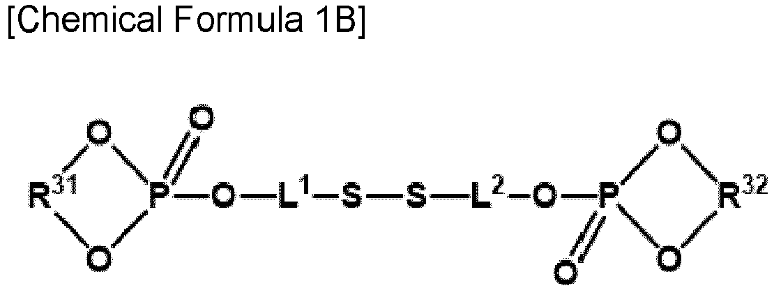
- wherein, in Chemical Formula 1B,
- R31 and R32 are each independently a substituted or unsubstituted C2 to C10 alkylene group, and
- L1 and L2 are each independently a substituted or unsubstituted C1 to C20 alkylene group.
- In one or more embodiments, R11 to R30 may each independently be hydrogen, a halogen, or a substituted or unsubstituted C1 to C5 alkyl group, n1 to n4 may each independently be one of an integer of 0 to 3, and L1 and L2 may each independently be a substituted or unsubstituted C2 to C20 alkylene group.
- In one or more embodiments, R11 to R30 may each independently be hydrogen, a halogen, or a substituted or unsubstituted C1 to C3 alkyl group, n1 to n4 are each independently an integer of 0 to 2, and L1 and L2 may each independently be a substituted or unsubstituted C2 to C10 alkylene group.
- In one or more embodiments, R31 and R32 may each independently be a substituted or unsubstituted C2 to C5 alkylene group, and L1 and L2 may each independently be a substituted or unsubstituted C2 to C20 alkylene group.
- In one or more embodiments, R31 and R32 may each independently be a substituted or unsubstituted C2 to C4 alkylene group, and L1 and L2 may each independently be a substituted or unsubstituted C2 to C10 alkylene group.
- For example, Chemical Formula 1B may be represented by Chemical Formula 1B- I or Chemical Formula 1B-II.


- In Chemical Formula 1B- I and Chemical Formula 1B-II,
- R101 to R120 are each independently hydrogen, a halogen, or a substituted or unsubstituted C1 to C10 alkyl group, and
- L1 and L2 are the same as described above.
- In one or more embodiments, R101 to R120 may each independently be hydrogen, a halogen, or a substituted or unsubstituted C1 to C5 alkyl group.
- In one or more embodiments, each of R101 to R120 may be hydrogen.
- As another example, the additive may be represented by Chemical Formula 2A or Chemical Formula 2B.

- In Chemical Formula 2A,
- R33 to R52 are each independently hydrogen, a halogen, or a substituted or unsubstituted C1 to C10 alkyl group,
- n5 to n8 are each independently an integer of 0 to 4, and
- L3 and L4 are each independently a substituted or unsubstituted C1 to C20 alkylene group;

- wherein, in Chemical Formula 2B,
- R53 and R54 are each independently a substituted or unsubstituted C2 to C10 alkylene group, and
- L3 and L4 are each independently a substituted or unsubstituted C1 to C20 alkylene group.
- In one or more embodiments, R33 to R52 may each independently be hydrogen, a halogen or a substituted or unsubstituted C1 to C5 alkyl group, n5 to n8 may each independently be one of an integer of 0 to 3, and L3 and L4 may each independently be a substituted or unsubstituted C2 to C20 alkylene group.
- In one or more embodiments, R33 to R52 may each independently be hydrogen, a halogen, or a substituted or unsubstituted C1 to C3 alkyl group, n5 to n8 may each independently be one of an integer of 0 to 2, and L3 and L4 may each independently be a substituted or unsubstituted C2 to C10 alkylene group.
- In one or more embodiments, R53 and R54 may each independently be a substituted or unsubstituted C2 to C5 alkylene group, and L3 and L4 may each independently be a substituted or unsubstituted C2 to C20 alkylene group.
- In one or more embodiments, R53 and R54 may each independently be a substituted or unsubstituted C2 to C4 alkylene group, and L3 and L4 may each independently be a substituted or unsubstituted C2 to C10 alkylene group.
- For example, Chemical Formula 2B may be represented by Chemical Formula 2B- I or Chemical Formula 2B-II.


- In Chemical Formula 2B- I and Chemical Formula 2B-II,
- R121 to R140 are each independently hydrogen, a halogen, or a substituted or unsubstituted C1 to C10 alkyl group, and
- L3 and L4 are the same as described above.
- In one or more embodiments, R121 to R140 may each independently be hydrogen, a halogen or a substituted or unsubstituted C1 to C5 alkyl group.
- In one or more embodiments, R121 to R140 may each be hydrogen.
- The additive according to one or more embodiments of the present disclosure may be represented by Chemical Formula 1B- I -1 or Chemical Formula 2B- I -1.


- In Chemical Formula 1B- I -1 and Chemical Formula 2B- I -1,
- R101 to R108, R121 to R128, and R141 to R156 are each independently hydrogen, a halogen, or a substituted or unsubstituted C1 to C10 alkyl group,
- L3 and L4 are the same as described above.
- In one or more embodiments, R101 to R108, R121 to R128, and R141 to R156 may each independently be hydrogen, a halogen, or a substituted or unsubstituted C1 to C5 alkyl group.
- In one or more embodiments, R101 to R108, R121 to R128, and R141 to R156 may each be hydrogen.
- The additive may be included in an amount of about 0.001 to 0.05 parts by weight based on 100 parts by weight of the positive electrode active material, the binder, and the conductive material.
- For example, the additive may be included in an amount of about 0.005 to 0.05 parts by weight based on 100 parts by weight of the positive electrode active material, the binder, and the conductive material.
- The additive may improve storage characteristics at a high temperature by combining with the positive electrode active material to form a film on the surface of the positive electrode, and in particular, when added in the above content range, a degree of improvement (i.e. reduction) in the amount of gas generated may be significantly exhibited without increasing resistance.
The positive electrode active material may include lithiated intercalation compounds that reversibly intercalate and deintercalate lithium ions. - Specifically, the positive electrode active material may include at least one of composite oxides of a metal selected from cobalt, manganese, nickel, iron, and a combination thereof, and lithium.
- Of course, one in which a portion of the metal of the composite oxide may be substituted with another suitable metal, for example, may be at least one selected from LiNiPO4, LiFePO4, LiCoPO4, and LiMnPO4, and composite oxide having a coating layer on the surface thereof or a mixture of the composite oxide and the composite oxide having a coating layer may be used. The coating layer may include at least one coating element compound selected from an oxide of a coating element, a hydroxide of a coating element, an oxyhydroxide of a coating element, an oxycarbonate of a coating element, and a hydroxycarbonate of a coating element. The compound for the coating layer may be amorphous or crystalline. As the coating element included in the coating layer, Mg, Al, Co, K, Na, Ca, Si, Ti, V, Sn, Ge, Ga, B, As, Zr, or a mixture thereof may be used. The coating layer may be disposed by a method having no adverse influence on properties of a positive electrode active material by using these elements in the compound. For example, the method may include any coating method such as spray coating, dipping, and the like, but is not illustrated in more detail since it is well-known to those who work in the related field.
- The positive electrode active material may be, for example, at least one of lithium composite oxides represented by
Chemical Formula 4.
[Chemical Formula 4] LixM1 yM2 zM3 1-y-zO2±aXb
- In
Chemical Formula 4,
0.5≤x≤1.8, 0≤a≤0.1, 0≤b≤0.1, 0<y≤1, 0≤z≤1, 0<y+z≤1, M1, M2, and M3 are each independently one or more elements selected from Ni, Co, Mn, Al, B, Ba, Ca, Ce, Cr, Fe, Mo, Nb, Si, Sr, Mg, Ti, V, W, Zr, or La, and a combination thereof, and X is one or more elements selected from F, S, P, or Cl. - In one or more embodiments the positive electrode active material may be at least one selected from LiCoO2, LiNiO2, LiMnO2, LiMn2O4, LiNiaMnbCocO2 (a+b+c=1), LiNiaMnbCocAldO2 (a+b+c+d=1), and LiNieCofAlgO2 (e+f+g=1).
- For example, in
Formula 4, 0.8≤y≤1, 0≤z≤0.2, and M1 may be Ni. - For example, the positive electrode active material selected from LiNibMncCodO2 (b+c+d=1), LiNibMncCodAleO2 (b+c+d+e=1), and LiNibCodAleO2 (b+d+e=1) may be a high Ni-based positive electrode active material.
- For example, in the case of the LiNibMncCodO2 (b+c+d=1) and LiNibMncCodAleO2 (b+c+d+e=1), the nickel content may be greater than or equal to about 60% (b ≥ 0.6), and more specifically, greater than or equal to about 80% (b ≥ 0.8).
- For example, in the case of LiNibCodAleO2 (b+d+e=1), the nickel content may be greater than or equal to about 60% (b ≥ 0.6), and more specifically, greater than or equal to about 80% (b ≥ 0.8).
- A content of the positive electrode active material may be about 90 wt% to about 98 wt% based on the total weight of the positive electrode composition.
- A content of the conductive material and the binder may be about 1 wt% to about 5 wt% based on the total weight of the positive electrode composition, respectively.
- The conductive material is included to impart conductivity to the positive electrode, and any electrically conductive material may be used as a conductive material unless it causes a chemical change in a battery. Examples of the conductive material may include a carbon-based material such as natural graphite, artificial graphite, carbon black, acetylene black, ketjen black, carbon fiber, and the like; a metal-based material of a metal powder or a metal fiber including copper, nickel, aluminium, silver, and the like; a conductive polymer such as a polyphenylene derivative; or a mixture thereof.
- The binder improves binding properties of positive electrode active material particles with one another and with a current collector. Examples thereof may be polyvinyl alcohol, carboxylmethyl cellulose, hydroxypropyl cellulose, diacetyl cellulose, polyvinylchloride, carboxylated polyvinylchloride, polyvinylfluoride, an ethylene oxide-containing polymer, polyvinylpyrrolidone, polyurethane, polytetrafluoroethylene, polyvinylidene fluoride, polyethylene, polypropylene, a styrene-butadiene rubber, an acrylated styrene-butadiene rubber, an epoxy resin, nylon, and the like, but are not limited thereto.
- Another embodiment provides a rechargeable lithium battery including the aforementioned positive electrode; a negative electrode including a negative electrode active material; and an electrolyte solution for a rechargeable lithium battery.
- The positive electrode includes a positive electrode current collector and a positive electrode active material layer on the positive electrode current collector, and the positive electrode active material layer includes the positive electrode active material.
- The positive electrode current collector may include Al, but is not limited thereto.
- The negative electrode includes a negative electrode current collector and a negative electrode active material layer including a negative electrode active material formed on the negative electrode current collector.
- The negative electrode active material may include a material that reversibly intercalates/deintercalates lithium ions, a lithium metal, a lithium metal alloy, a material capable of doping/dedoping lithium, or a transition metal oxide.
- The material that reversibly intercalates/deintercalates lithium ions may include a carbon material. The carbon material may be any generally-used carbon-based negative electrode active material in a rechargeable lithium battery. Examples thereof may be crystalline carbon, amorphous carbon, or a mixture thereof. The crystalline carbon may be non-shaped, or sheet, flake, spherical, or fiber shaped natural graphite or artificial graphite. The amorphous carbon may be a soft carbon, a hard carbon, a mesophase pitch carbonization product, calcined coke, and the like.
- The lithium metal alloy includes an alloy of lithium and a metal selected from Na, K, Rb, Cs, Fr, Be, Mg, Ca, Sr, Si, Sb, Pb, In, Zn, Ba, Ra, Ge, Al, and Sn.
- The material capable of doping/dedoping lithium may be Si, a Si-C composite, SiOx (0 < x < 2), a Si-Q alloy wherein Q is an element selected from an alkali metal, an alkaline-earth metal, a Group 13 element, a Group 14 element except for Si, a Group 15 element, a Group 16 element, a transition metal, a rare earth element, and a combination thereof, Sn, SnO2, Sn-R11 wherein R11 is an element selected from an alkali metal, an alkaline-earth metal, a Group 13 element, a Group 14 element except for Sn, a Group 15 element, a Group 16 element, a transition metal, a rare earth element, and a combination thereof. At least one of these materials may be mixed with SiO2.
- The elements Q and R11 may be selected from Mg, Ca, Sr, Ba, Ra, Sc, Y, Ti, Zr, Hf, Rf, V, Nb, Ta, Db, Cr, Mo, W, Sg, Tc, Re, Bh, Fe, Pb, Ru, Os, Hs, Rh, Ir, Pd, Pt, Cu, Ag, Au, Zn, Cd, B, Al, Ga, Sn, In, Tl, Ge, P, As, Sb, Bi, S, Se, Te, Po, and a combination thereof.
- The transition metal oxide may be vanadium oxide, lithium vanadium oxide, or lithium titanium oxide.
- In one or more embodiments, the negative electrode active material may include at least one of graphite and a Si composite.
- The Si composite may include a core including Si-based particles and an amorphous carbon coating layer, and for example, the Si-based particles may include at least one of Si particles, a Si-C composite, SiOx (0 < x ≤ 2), and a Si alloy.
- The central portion of the core including Si-based particles may include voids, and a radius of the central portion may correspond to about 30% to about 50% of the radius of the Si composite, an average particle diameter of the Si composite may be about 5µm to 20µm, and an average particle diameter of the Si-based particles may be about 10 nm to about 200 nm.
- In the present disclosure, an average particle diameter may be particle size (D50) at a volume ratio of 50% in a cumulative size-distribution curve. For example, the average particle diameter may be, for example, a median diameter (D50) measured utilizing a laser diffraction particle diameter distribution meter.
- When the Si-based particles have an average particle diameter within the range, volume expansion during the charge and discharge may be suppressed, and interruption of a conductive path due to particle crushing during the charge and discharge may be prevented or reduced.
- The core including the Si-based particles further includes amorphous carbon, and in this case, the central portion does not include amorphous carbon, and the amorphous carbon may present only on the surface portion of the Si composite.
- Herein, the surface portion refers to a region from the outermost surface of the center portion to the outermost surface of the Si composite.
- In addition, the Si-based particles are substantially uniformly included in the Si composite as whole, that is, the Si-based particles may be present in a substantially uniform concentration in the central portion and the surface portion of the Si composite.
- The amorphous carbon may be soft carbon, hard carbon, mesophase pitch carbonized product, calcined coke, or a combination thereof.
- The amorphous carbon precursor may include a coal-based pitch, mesophase pitch, petroleum-based pitch, coal-based oil, petroleum-based heavy oil, or a polymer resin such as a phenol resin, a furan resin, or a polyimide resin.
- For example, the Si-C composite may include Si particles and crystalline carbon.
- The Si particles may be included in an amount of about 1 wt% to about 60 wt%, for example, about 3 wt% to about 60 wt%, based on the total weight of the Si-C composite.
- The crystalline carbon may be, for example, graphite, and specifically, natural graphite, artificial graphite, or a combination thereof.
- An average particle diameter of the crystalline carbon may be about 5 µm to about 30 µm.
- When the negative electrode active material includes the Si composite and the graphite together, the Si composite and the graphite may be included as a mixture, wherein the Si composite and the graphite may be included in a weight ratio of about 1:99 to about 50:50. For example, the Si composite and the graphite may be included in a weight ratio of about 3:97 to about 20:80 or about 5:95 to about 20:80.
- In the negative electrode active material layer, the negative electrode active material may be included in an amount of about 95 wt% to about 99 wt% based on the total weight of the negative electrode active material layer.
- In an embodiment of the present disclosure, the negative electrode active material layer includes a binder, and optionally a conductive material. In the negative electrode active material layer, a content of the binder may be about 1 wt% to about 5 wt% based on the total weight of the negative electrode active material layer. When it further includes the conductive material, it may include about 90 wt% to about 98 wt% of the negative electrode active material, about 1 wt% to about 5 wt% of the binder, and about 1 wt% to about 5 wt% of the conductive material.
- The binder improves binding properties of negative electrode active material particles with one another and with a negative electrode current collector. The binder may be a non-water-soluble binder, a water-soluble binder, or a combination thereof.
- The non-water-soluble binder may be polyvinylchloride, carboxylated polyvinylchloride, polyvinylfluoride, polyurethane, polytetrafluoroethylene, polyvinylidene fluoride, polyethylene, polypropylene, polyamideimide, polyimide, or a combination thereof.
- The water-soluble binder may be a rubber-based binder or a polymer resin binder. The rubber-based binder may be selected from a styrene-butadiene rubber, an acrylated styrene-butadiene rubber (SBR), an acrylonitrile-butadiene rubber, an acrylic rubber, a butyl rubber, a fluorine rubber, and a combination thereof. The polymer resin binder may be selected from polytetrafluoroethylene, ethylene propylene copolymer, polyethyleneoxide, polyvinylpyrrolidone, polyepichlorohydrin, polyphosphazene, polyacrylonitrile, polystyrene, an ethylene propylene diene copolymer, polyvinylpyridine, chlorosulfonated polyethylene, latex, a polyester resin, an acrylic resin, phenolic resin, an epoxy resin, polyvinyl alcohol, and a combination thereof.
- When the water-soluble binder is used as the negative electrode binder, a cellulose-based compound may be further used to provide viscosity as a thickener. The cellulose-based compound includes one or more of carboxylmethyl cellulose, hydroxypropylmethyl cellulose, methyl cellulose, or alkali metal salts thereof. The alkali metal may be Na, K, or Li. Such a thickener may be included in an amount of about 0.1 to about 3 parts by weight based on 100 parts by weight of the negative electrode active material.
- The conductive material is included to impart electrode conductivity. Any electrically conductive material may be used as a conductive material unless it causes a chemical change. Examples of the conductive material include a carbon-based material such as natural graphite, artificial graphite, carbon black, acetylene black, ketjen black, a carbon fiber, and the like; a metal-based material of a metal powder or a metal fiber including copper, nickel, aluminium, silver, and the like; a conductive polymer such as a polyphenylene derivative; or a mixture thereof.
- The negative electrode current collector may include one selected from a copper foil, a nickel foil, a stainless steel foil, a titanium foil, a nickel foam, a copper foam, a polymer substrate coated with a conductive metal, and a combination thereof.
- The electrolyte solution for a rechargeable lithium battery includes a non-aqueous organic solvent and a lithium salt.
- The non-aqueous organic solvent serves as a medium for transmitting ions taking part in the electrochemical reaction of a battery.
- The non-aqueous organic solvent may be a carbonate-based, ester-based, ether-based, ketone-based, alcohol-based, or aprotic solvent.
- The carbonate-based solvent may be dimethyl carbonate (DMC), diethyl carbonate (DEC), dipropyl carbonate (DPC), methylpropyl carbonate (MPC), ethylpropyl carbonate (EPC), ethylmethyl carbonate (EMC), ethylene carbonate (EC), propylene carbonate (PC), butylene carbonate (BC), and the like. The ester-based solvent may be methyl acetate, ethyl acetate, n-propyl acetate, t-butyl acetate, methyl propionate, ethyl propionate, propyl propionate, decanolide, mevalonolactone, caprolactone, and the like. The ether-based solvent may be dibutyl ether, tetraglyme, diglyme, dimethoxyethane, 2-methyltetrahydrofuran, tetrahydrofuran, and the like. In addition, the ketone-based solvent may be cyclohexanone, and the like. In addition, the alcohol-based solvent may be ethyl alcohol, isopropyl alcohol, etc. and the aprotic solvent may be nitriles such as R1-CN (where R1 is a C2 to C20 linear, branched, or cyclic hydrocarbon group and may include a double bond, an aromatic ring, or an ether bond), amides such as dimethylformamide, dioxolanes such as 1,3-dioxolane, sulfolanes, and the like.
- The non-aqueous organic solvent may be used alone or in a mixture. When the non-aqueous organic solvent is used in a mixture, the mixture ratio may be controlled in accordance with a desirable battery performance.
- The carbonate-based solvent is prepared by mixing a cyclic carbonate and a chain carbonate. In this case, when the cyclic carbonate and the chain carbonate are mixed in a volume ratio of about 1:9 to about 9:1, performance of the electrolyte solution may be improved.
- In particular, in an embodiment, the non-aqueous organic solvent may include the cyclic carbonate and the chain carbonate in a volume ratio of about 2:8 to about 5:5, and as a specific example, the cyclic carbonate and the chain carbonate may be included in a volume ratio of about 2:8 to about 4:6.
- As a more specific example, the cyclic carbonate and the chain carbonate may be included in a volume ratio of about 2:8 to about 3:7.
- The non-aqueous organic solvent may further include an aromatic hydrocarbon-based organic solvent in addition to the carbonate-based solvent. In this case, the carbonate-based solvent and the aromatic hydrocarbon-based organic solvent may be mixed in a volume ratio of about 1:1 to about 30:1.
- The aromatic hydrocarbon-based solvent may be an aromatic hydrocarbon-based compound represented by Chemical Formula 3.

- In Chemical Formula 3, R3 to R8 are the same as or different from each other and are selected from hydrogen, a halogen, a C1 to C10 alkyl group, a C1 to C10 haloalkyl group, and a combination thereof.
- Specific examples of the aromatic hydrocarbon-based solvent may be selected from benzene, fluorobenzene, 1,2-difluorobenzene, 1,3-difluorobenzene, 1,4-difluorobenzene, 1,2,3-trifluorobenzene, 1,2,4-trifluorobenzene, chlorobenzene, 1,2-dichlorobenzene, 1,3-dichlorobenzene, 1,4-dichlorobenzene, 1,2,3-trichlorobenzene, 1,2,4-trichlorobenzene, iodobenzene, 1,2-diiodobenzene, 1,3-diiodobenzene, 1,4-diiodobenzene, 1,2,3-triiodobenzene, 1,2,4-triiodobenzene, toluene, fluorotoluene, 2,3-difluorotoluene, 2,4-difluorotoluene, 2,5-difluorotoluene, 2,3,4-trifluorotoluene, 2,3,5-trifluorotoluene, chlorotoluene, 2,3-dichlorotoluene, 2,4-dichlorotoluene, 2,5-dichlorotoluene, 2,3,4-trichlorotoluene, 2,3,5-trichlorotoluene, iodotoluene, 2,3-diiodotoluene, 2,4-diiodotoluene, 2,5-diiodotoluene, 2,3,4-triiodotoluene, 2,3,5-triiodotoluene, xylene, and a combination thereof.
- The electrolyte solution for a rechargeable lithium battery may further include at least one other additive of vinylene carbonate (VC), fluoroethylene carbonate (FEC), difluoroethylene carbonate, chloroethylene carbonate, dichloroethylene carbonate, bromoethylene carbonate, dibromoethylene carbonate, nitroethylene carbonate, cyanoethylene carbonate, vinylethylene carbonate (VEC), adiponitrile (AN), succinonitrile (SN), 1,3,6-hexane tricyanide (HTCN), propenesultone (PST), propanesultone (PS), lithium tetrafluoroborate (LiBF4), lithium difluorophosphate (LiPO2F2), and 2-fluoro biphenyl (2-FBP).
- By further including the aforementioned other additives, cycle-life may be further improved or gases generated from the positive electrode and the negative electrode may be effectively controlled during high-temperature storage.
- The other additives may be included in an amount of about 0.2 to 20 parts by weight, specifically about 0.2 to 15 parts by weight, for example, about 0.2 to 10 parts by weight, based on 100 parts by weight of the electrolyte solution for a rechargeable lithium battery.
- When the content of other additives is as described above, the increase in film resistance may be minimized, thereby contributing to the improvement of battery performance.
- The lithium salt dissolved in the non-aqueous organic solvent supplies lithium ions in a battery, enables a basic operation of a rechargeable lithium battery, and improves transportation of the lithium ions between positive and negative electrodes. Examples of the lithium salt may include at least one selected from LiPF6, LiBF4, LiSbF6, LiAsF6, LiN(SO2C2F5)2, Li(CF3SO2)2N, LiN(SO3C2F5)2, Li(FSO2)2N (lithium bis(fluorosulfonyl)imide: LiFSI), LiC4F9SO3, LiClO4, LiAlO2, LiAlCl4, LiPO2F2, LiN(CxF2x+1SO2)(CyF2y+1SO2) (wherein x and y are natural numbers, for example, an integer ranging from 1 to 20), LiCl, Lil, LiB(C2O4)2 (lithium bis(oxalato) borate: LiBOB), LiDFOB (lithium difluoro(oxalato)borate), and Li[PF2(C2O4)2] (lithium difluoro(bisoxalato) phosphate). The lithium salt may be used in a concentration ranging from about 0.1 M to about 2.0 M. When the lithium salt is included at the above concentration range, an electrolyte may have excellent performance and lithium ion mobility due to optimal electrolyte conductivity and viscosity.
- The rechargeable lithium battery may further include a separator between the negative electrode and the positive electrode, depending on a type of the battery. Such a separator may be a porous substrate or a composite porous substrate.
- The porous substrate may be a substrate including pores, and lithium ions may move through the pores. The porous substrate may, for example, include polyethylene, polypropylene, polyvinylidene fluoride, and multi-layers thereof such as a polyethylene/polypropylene double-layered separator, a polyethylene/polypropylene/polyethylene triple-layered separator, and a polypropylene/polyethylene/polypropylene triple-layered separator.
- The composite porous substrate may have a form including a porous substrate and a functional layer on the porous substrate. The functional layer may be, for example, at least one of a heat-resistant layer and an adhesive layer from the viewpoint of enabling additional function. For example, the heat-resistant layer may include a heat-resistant resin and optionally a filler.
- In addition, the adhesive layer may include an adhesive resin and optionally a filler.
- The filler may be an organic filler or an inorganic filler.
- As an example of the rechargeable lithium battery, a cylindrical rechargeable lithium battery will be described.
FIG. 1 schematically shows the structure of a rechargeable lithium battery according to an embodiment. Referring toFIG. 1 , arechargeable lithium battery 100 according to an embodiment includes a battery cell including apositive electrode 114, anegative electrode 112 facing thepositive electrode 114, and aseparator 113 between thepositive electrode 114 and thenegative electrode 112, and an electrolyte solution (not shown) impregnating thepositive electrode 114, thenegative electrode 112 and theseparator 113, abattery container 120 housing the battery cell, and a sealingmember 140 for sealing thecontainer 120. - Hereinafter, examples of the present disclosure and comparative examples are described. These examples, however, are not in any sense to be interpreted as limiting the scope of the invention.
- LiNi0.88Co0.07Al0.05O2 as a positive electrode active material, polyvinylidene fluoride as a binder, and acetylene as a black conductive material were mixed in a weight ratio of 96:2:2 and then, dispersed in N-methyl pyrrolidone, preparing positive electrode active material slurry.
- The positive electrode active material slurry was coated on a 14 µm-thick Al foil and then, dried at 110°C and pressed, manufacturing a positive electrode.
- Negative electrode active material slurry was prepared by mixing a mixture of artificial graphite and Si-C composite in a weight ratio of 93:7 as a negative electrode active material, a styrene-butadiene rubber as a binder, and carboxylmethyl cellulose as a thickener in a weight ratio of 97:1:2 and dispersing the obtained mixture in distilled water.
- The Si-C composite had a core including artificial graphite and silicon particles and coal pitch coated on the surface of the core.
- The negative electrode active material slurry was coated on a 10µm-thick Cu foil and then, dried at 100°C and pressed, manufacturing a negative electrode.
- The positive and negative electrodes were assembled with a 25µm-thick polyethylene separator to prepare an electrode assembly, and then, an electrolyte solution was injected thereinto, manufacturing a rechargeable lithium battery cell.
- The electrolyte solution had the following composition.
-
- Salt: LiPF6 1.15 M
- Solvent: ethylene carbonate: ethylmethyl carbonate: dimethyl carbonate (EC: EMC:DMC = volume ratio of 20:40:40)
- Other additive: 1 part by weight of vinylene carbonate (VC) and 1 part by weight of LiPO2F2
- (Herein, in the composition of the electrolyte solution, "parts by weight" means the relative weight of the additive based on 100 weight of the total (lithium salt + non-aqueous organic solvent) of the electrolyte solution excluding the additive.)
- A rechargeable lithium battery cell was manufactured in the same manner as in Comparative Example 1 except that 0.04 parts by weight of the additive represented by Chemical Formula a-1 were mixed based on 100 parts by weight of the positive electrode active material, the binder, and the conductive material and then, dispersed in N-methyl pyrrolidone.

- Each rechargeable lithium battery cell was manufactured in the same manner as in Example 1 except that the content of the additive represented by Chemical Formula a-1 was changed as shown in Table 1.
- A rechargeable lithium battery cell was manufactured in the same manner as in Comparative Example 1 except that the additive represented by Chemical Formula a-1 in an amount shown in Table 1 was added to the electrolyte solution.
(Table 1) Positive electrode additive Electrolyte solution additive Chemical Formula a-1 (parts by weight) Chemical Formula a-1 (parts by weight) Comparative Example 1 - - Comparative Example 2 0.0001 - Comparative Example 3 0.1 - Comparative Example 4 - 0.1 Example 1 0.04 - Example 2 0.02 - Example 3 0.01 - Example 4 0.005 - - The rechargeable lithium battery cells according to Examples 1 to 4, and Comparative Examples 1 to 3 were manufactured as a 30 mAh cell belonging to 4.2 V Class, which was allowed to stand at 70 °C for 3 days and measured with respect to an amount (ml) of generated gas in an Archimedes method, and the results are shown in Table 2.
- The rechargeable lithium battery cells according to Examples 1 to 4 and Comparative Examples 1 to 3 were measured with respect to △V/△I (voltage change / current change) to obtain initial DC resistance (DC-IR) and after making a maximum energy state inside the cells into a full-charge state (
SOC 100%) and storing them at 70 °C for 3 days in this state, remeasured with respect to DC resistance to calculate a DC resistance increase rate [{(DC-IR after 3 days)/(initial DC-IR)}*100], and the results are shown in Table 2.(Table 2) Gas amount (mL) Initial DC resistance (Ω) DC resistance after high-temperature storage @70°C/3D (Ω) DC resistance increase rate (%) Comparative Example 1 0.174 2.630 3.800 144.487 Comparative Example 2 0.173 2.629 3.802 144.618 Comparative Example 3 0.005 3.300 3.359 101.788 Example 1 0.047 2.630 2.710 130.042 Example 2 0.084 2.610 2.789 106.858 Example 3 0.129 2.620 2.830 108.015 Example 4 0.145 2.625 2.900 110.476 - Referring to Table 2, when the additive according to the present disclosure was included in the positive electrode composition, the amount of gas generated was significantly reduced, and the DC resistance increase rate after high-temperature storage relative to the initial DC resistance was relatively gradual.
- Accordingly, storage characteristics at a high temperature were improved.
- The positive electrodes according to Examples 1 to 3 and Comparative Example 1 were measured with respect to a heat flow according to a temperature through differential scanning calorimetry (DSC). A differential scanning calorimetry (SENSYS Evo, Setaram Instrumentation) was used, specifically, taking 15 mg of each electrode charged with 4.25 V (vs. Li/Li+), adding 20 µl of an electrolyte solution thereto, and then, heating the mixture at a rate of 10 °C/min (ramp rate) to 400 °C. The measured results are shown in
FIG. 2 . -
FIG. 2 is a graph showing the amount of heat flow according to temperature measured by differential scanning calorimetry (DSC) for the positive electrodes according to Examples 1 to 3 and Comparative Example 1. - Referring to
FIG. 2 , the positive electrodes according to Examples 1 to 3 exhibited a decreased exothermic amount near 200 °C and/or 230 °C, and a delayed peak temperature and thus, excellent high temperature stability, compared with the positive electrode according to Comparative Example 1. - The rechargeable lithium battery cells according to Example 1 and Comparative Example 1 were analyzed through XPS (X-ray Photoelectron Spectroscopy) to analyze components of each positive electrode film, and the results are shown in
FIGS. 3 and4 . -
FIGS. 3 and4 show XPS analysis results of the positive electrodes of the rechargeable lithium battery cells prepared according to Example 1 and Comparative Example 1. - Referring to
FIGS. 3 and4 , Example 1 exhibited an S2p peak of binding energy around 163 eV to 165 eV, but Comparative Example 1 exhibited no S2p peak. - In addition, Example 1 exhibited a P2p peak of binding energy around 133 eV to 135 eV, but P2p peak of binding energy around 133 eV to 135 eV was almost not detected in Comparative Example 1.
- Accordingly, the rechargeable lithium battery cells according to the examples of the present disclosure turned out to have a film in which the additive included in the positive electrode compositions was coordinated on the surfaces of the positive electrodes.
- After respectively allowing the electrolyte solutions of Comparative Examples 1 and 4 to stand at 45°C for 3 days, a colorimeter (PFXI-195, Lovibond) was used to measure a discoloring degree in an APHA chromaticity standard measurement method, and the results are shown in Table 3.
-
- 1. After filling the DIW (De-Ionized Water) in the sample cell, the blank is measured.
- 2. After filling the electrolyte solution sample in the sample cell, the chromaticity is measured.
- 3. The result value on the equipment screen is checked.
- The closer to 0 based on 500 APHA of a platinum cobalt standard solution, the more transparent, but the closer to 500 APHA, the more discolored.
- The standard electrolyte solution of Comparative Example 1, that is, an electrolyte solution including no additive according to the present disclosure, the electrolyte solution of Comparative Example 4, that is, an electrolyte solution including the additive according to the present disclosure, exhibited similar initial chromaticity, but after respectively allowing the electrolyte solutions of Comparative Examples 1 and 4 to stand at 45°C for 3 days, Comparative Example 1 exhibited 50 APHA, but Comparative Example 4 exhibited 200 APHA, which showed that when the additive according to the present disclosure was included in an electrolyte solution, a high discoloring degree was found.
- Electrochemical stability of the electrolyte solutions according to Comparative Example 1 and Comparative Example 4 was evaluated by measuring cyclic voltammetry (CV), and the results are shown in
FIG. 5 . - A negative electrode cyclic voltammetry (CV) was measured by using a triple electrode electrochemical cell using graphite as a working electrode and Li metals as a reference electrode and a counter electrode. Herein, scan was 3 cycles performed from 3 V to 0 V and from 0 V to 3 V at a rate of 0.1 mV/sec.
-
FIG. 5 is a graph showing the results of negative electrode cyclic voltammetry (CV) at room temperature of the electrolyte solutions according to Comparative Examples 1 and 4. - As shown in
FIG. 5 , the electrolyte solution of Comparative Example 4 exhibited a reduction decomposition peak near 1.5 V. Accordingly, the additive according to the present disclosure turned out to interact with the solvents in the electrolyte solution, and accordingly, the electrolyte solution of Comparative Example 4 was expected to form an initial Solid Electrolyte Interface (SEI) film on the negative electrode, reducing an amount of a complex compound produced from the additive at the positive electrode and thus deteriorating the surface protection effect of the positive electrode. - While this disclosure has been described in connection with what is presently considered to be practical example embodiments, it is to be understood that the invention is not limited to the disclosed embodiments, but, on the contrary, is intended to cover various modifications and equivalent arrangements included within the scope of the appended claims.
-
- 100:
- rechargeable lithium battery
- 112:
- negative electrode
- 113:
- separator
- 114:
- positive electrode
- 120:
- battery case
- 140:
- sealing member
| Initial color (APHA) | Chromaticity after high-temperature storage @45°C/3D (APHA) | |
| Comparative Example 1 | 35 | 50 |
| Comparative Example 4 | 36 | 200 |
Claims (15)
- A positive electrode, comprisinga positive electrode active material,a binder,a conductive material, andan additive represented by Chemical Formula 1 or Chemical Formula 2:

 wherein, in Chemical Formula 1 and Chemical Formula 2,R1 to R8 are each independently a substituted or unsubstituted C1 to C10 alkyl group, a substituted or unsubstituted C2 to C10 alkenyl group, a substituted or unsubstituted C3 to C10 cycloalkyl group, a substituted or unsubstituted C3 to C10 cycloalkenyl group, a substituted or unsubstituted C2 to C10 alkynyl group, a substituted or unsubstituted C3 to C10 cycloalkynyl group, or a substituted or unsubstituted C6 to C20 aryl group,R1 to R8 are each independently present, orat least one of R1 and R2; R3 and R4; R5 and R6; and R7 and R8 is linked to form a substituted or unsubstituted C2 to C30 monocyclic or C2 to C50 polycyclic aliphatic heterocycle, or a substituted or unsubstituted C2 to C30 monocyclic or C2 to C50 polycyclic aromatic heterocycle, andL1 to L4 are each independently a substituted or unsubstituted C1 to C20 alkylene group.
 - The positive electrode of claim 1, whereinChemical Formula 1 is represented by Chemical Formula 1A or Chemical Formula 1B:
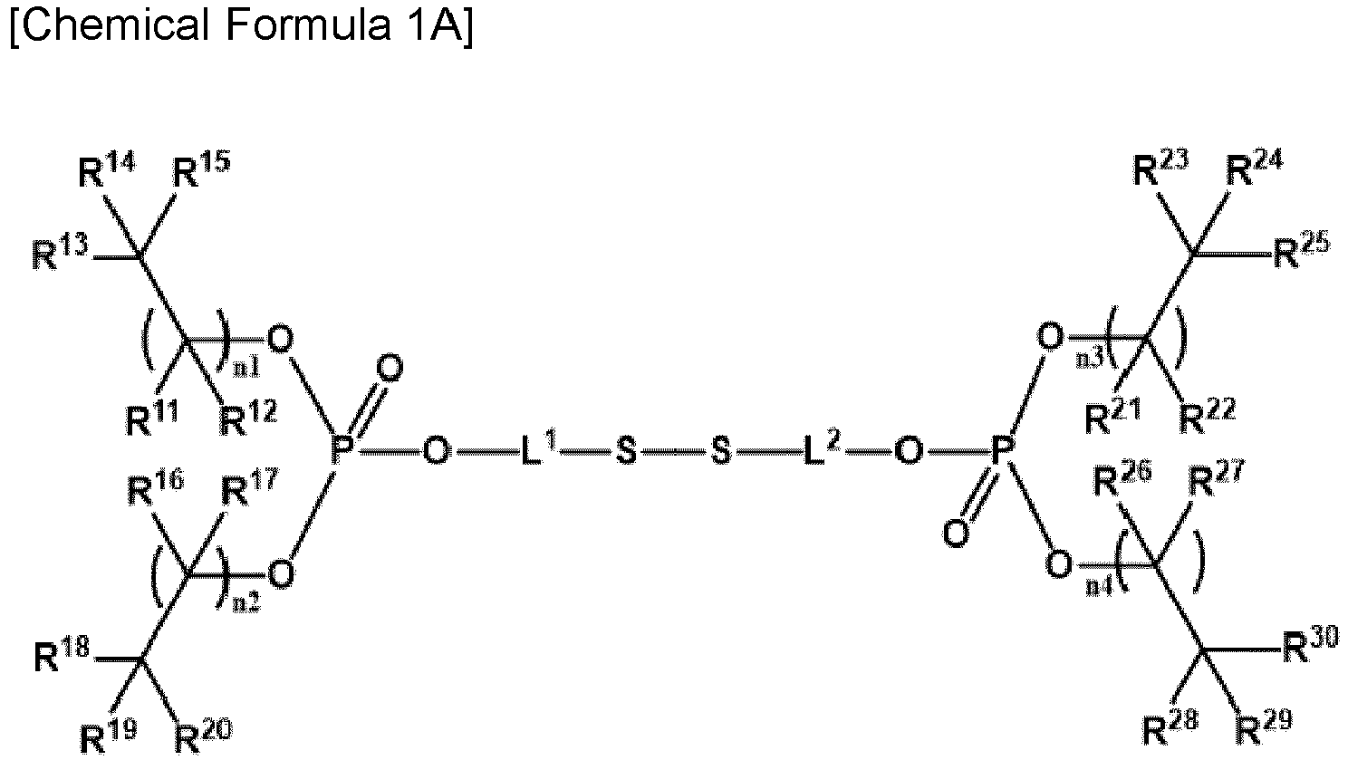 wherein, in Chemical Formula 1A,R11 to R30 are each independently hydrogen, a halogen, or a substituted or unsubstituted C1 to C10 alkyl group,n1 to n4 are each independently an integer of 0 to 4, andL1 and L2 are each independently a substituted or unsubstituted C1 to C20 alkylene group;
 wherein, in Chemical Formula 1B,R31 and R32 are each independently a substituted or unsubstituted C2 to C10 alkylene group, andL1 and L2 are each independently a substituted or unsubstituted C1 to C20 alkylene group.
 - The positive electrode of claim 2, whereinChemical Formula 1B is represented by Chemical Formula 1B- I or Chemical Formula 1B-II:
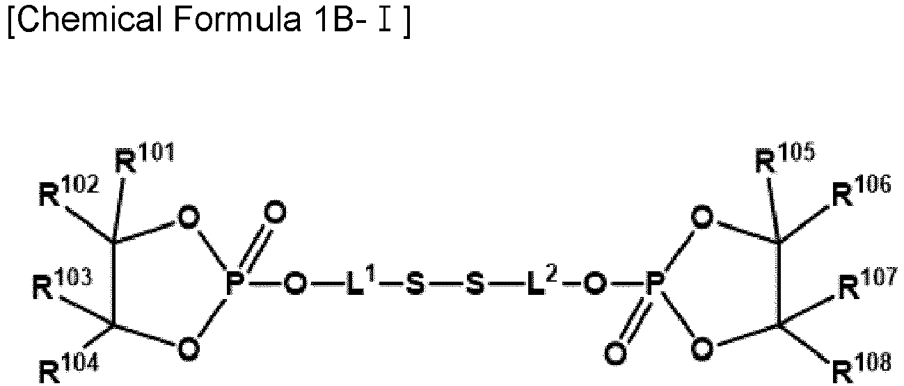

 wherein, in Chemical Formula 1B- I and Chemical Formula 1B-II,R101 to R120 are each independently hydrogen, a halogen, or a substituted or unsubstituted C1 to C10 alkyl group, andL1 and L2 are each independently a substituted or unsubstituted C1 to C20 alkylene group.
 - The positive electrode of claim 1, whereinChemical Formula 2 is represented by Chemical Formula 2A or Chemical Formula 2B:
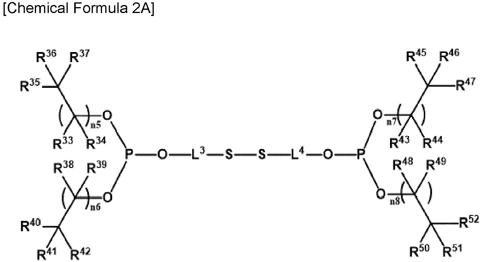 wherein, in Chemical Formula 2A,R33 to R52 are each independently hydrogen, a halogen, or a substituted or unsubstituted C1 to C10 alkyl group,n5 to n8 are each independently an integer of 0 to 4, andL3 and L4 are each independently a substituted or unsubstituted C1 to C20 alkylene group;
 wherein, in Chemical Formula 2B,R53 and R54 are each independently a substituted or unsubstituted C2 to C10 alkylene group, andL3 and L4 are each independently a substituted or unsubstituted C1 to C20 alkylene group.
 - The positive electrode of claim 4, whereinChemical Formula 2B is represented by Chemical Formula 2B- I or Chemical Formula 2B-II:


 wherein, in Chemical Formula 2B- I and Chemical Formula 2B-II,R121 to R140 are each independently hydrogen, a halogen, or a substituted or unsubstituted C1 to C10 alkyl group, andL3 and L4 are each independently a substituted or unsubstituted C1 to C20 alkylene group.
 - The positive electrode of claim 1, whereinChemical Formula 1 is represented by Chemical Formula 1B- I -1 or Chemical Formula 2B- I -1:


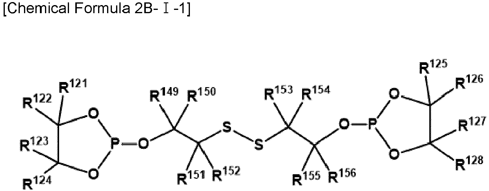 wherein, in Chemical Formula 1B- I -1 and Chemical Formula 2B- I -1,R101 to R108, R121 to R128, and R141 to R156 are each independently hydrogen, a halogen, or a substituted or unsubstituted C1 to C10 alkyl group.
 - The positive electrode of any one of claims 1 to 6, wherein
the additive is included in an amount of about 0.001 to 0.05 parts by weight based on 100 parts by weight of the positive electrode active material, the binder, and the conductive material. - The positive electrode of any one of claims 1 to 6, wherein
the additive is included in an amount of about 0.005 to 0.05 parts by weight based on 100 parts by weight of the positive electrode active material, the binder, and the conductive material. - The positive electrode of claim 1, whereinthe positive electrode active material is represented by Chemical Formula 4:
[Chemical Formula 4] LixM1 yM2 zM3 1-y-zO2±aXb
wherein, in Chemical Formula 4,0.5≤x≤1.8, 0≤a≤0.1, 0≤b≤0.1, 0<y≤1, 0≤z≤1, 0<y+z≤1, M1, M2, and M3 are each independently one or more elements selected from Ni, Co, Mn, Al, B, Ba, Ca, Ce, Cr, Fe, Mo, Nb, Si, Sr, Mg, Ti, V, W, Zr, or La, and a combination thereof, and X is one or more elements selected from F, S, P, or Cl. - The positive electrode of claim 9, whereinwherein, in Chemical Formula 4,0.8≤y≤1, 0≤z≤0.2, and M1 is Ni.
- A rechargeable lithium battery, comprisingthe positive electrode of any one of claim 1 to claim 10;a negative electrode including a negative electrode active material; andan electrolyte solution for the rechargeable lithium battery.
- The rechargeable lithium battery of claim 11, whereina positive electrode film is further included on the surface of the positive electrode, andthe positive electrode film is formed by coordinating the additive represented by Chemical Formula 1 or Chemical Formula 2 to the positive electrode active material.
- The rechargeable lithium battery of claim 11 or claim 12, wherein
the negative electrode active material includes at least one of graphite and Si composite. - The rechargeable lithium battery of claim 13, wherein
the Si composite includes a core including Si-based particles and an amorphous carbon coating layer. - The rechargeable lithium battery of claim 14, wherein
the Si-based particles includes at least one of Si particles, a Si-C composite, SiOx (0 < x ≤ 2), and a Si alloy.
Applications Claiming Priority (1)
| Application Number | Priority Date | Filing Date | Title |
|---|---|---|---|
| KR1020220093413A KR102816122B1 (en) | 2022-07-27 | 2022-07-27 | Positive electrode, and rechargeable lithium battery including the same |
Publications (3)
| Publication Number | Publication Date |
|---|---|
| EP4312284A2 true EP4312284A2 (en) | 2024-01-31 |
| EP4312284A3 EP4312284A3 (en) | 2024-02-28 |
| EP4312284B1 EP4312284B1 (en) | 2026-03-04 |
Family
ID=85172753
Family Applications (1)
| Application Number | Title | Priority Date | Filing Date |
|---|---|---|---|
| EP23154760.5A Active EP4312284B1 (en) | 2022-07-27 | 2023-02-02 | Positive electrode, and rechargeable lithium battery including the same |
Country Status (4)
| Country | Link |
|---|---|
| US (1) | US20240047671A1 (en) |
| EP (1) | EP4312284B1 (en) |
| KR (1) | KR102816122B1 (en) |
| CN (1) | CN117476869A (en) |
Families Citing this family (2)
| Publication number | Priority date | Publication date | Assignee | Title |
|---|---|---|---|---|
| WO2025249990A1 (en) * | 2024-05-28 | 2025-12-04 | 주식회사 엘지에너지솔루션 | Positive electrode for lithium secondary battery comprising positive electrode additive |
| KR20250176601A (en) * | 2024-06-12 | 2025-12-22 | 삼성에스디아이 주식회사 | Additive for positive electrode for rechargeable battery, Positive electrode slurry including the same and Rechargeable lithium battery including the same |
Family Cites Families (9)
| Publication number | Priority date | Publication date | Assignee | Title |
|---|---|---|---|---|
| US4472487A (en) * | 1983-11-30 | 1984-09-18 | Allied Corporation | Battery having polymeric anode coated with reaction product of oxirane compound |
| CA2308277A1 (en) * | 1997-11-03 | 1999-05-14 | Ronald H. Kluger | Hemoglobin with chemically introduced disulfide cross-links and preparation thereof |
| CA2242017A1 (en) * | 1998-06-25 | 1999-12-25 | Hydro-Quebec | Dual function block polymerization monomers; their applications, especially in the preparation of ionic conductors |
| KR101559444B1 (en) * | 2011-03-04 | 2015-10-12 | 가부시키가이샤 덴소 | Nonaqueous electrolyte solution for batteries, and nonaqueous electrolyte secondary battery using same |
| JP5601361B2 (en) * | 2012-10-12 | 2014-10-08 | 日産自動車株式会社 | Battery electrode |
| KR102270113B1 (en) * | 2017-05-25 | 2021-06-28 | 주식회사 엘지에너지솔루션 | Method for preparing positive electrode, positive electrode for secondary battery prepared by the same and lithium secondary battery comprising the same |
| CN111217856A (en) * | 2020-01-22 | 2020-06-02 | 恒大新能源技术(深圳)有限公司 | Five-membered cyclic phosphate compound and preparation method and application thereof |
| KR102864156B1 (en) * | 2020-06-11 | 2025-09-24 | 주식회사 엘지에너지솔루션 | Positive electrode for lithium-sulfur battery and lithium-sulfur battery comprising thereof |
| KR102700152B1 (en) * | 2020-08-25 | 2024-08-27 | 삼성에스디아이 주식회사 | Additive, electrolyte for rechargeable lithium battery and rechargeable lithium battery |
-
2022
- 2022-07-27 KR KR1020220093413A patent/KR102816122B1/en active Active
-
2023
- 2023-02-02 EP EP23154760.5A patent/EP4312284B1/en active Active
- 2023-02-13 CN CN202310106012.1A patent/CN117476869A/en active Pending
- 2023-04-19 US US18/303,343 patent/US20240047671A1/en active Pending
Also Published As
| Publication number | Publication date |
|---|---|
| US20240047671A1 (en) | 2024-02-08 |
| KR20240015482A (en) | 2024-02-05 |
| EP4312284A3 (en) | 2024-02-28 |
| CN117476869A (en) | 2024-01-30 |
| KR102816122B1 (en) | 2025-05-30 |
| EP4312284B1 (en) | 2026-03-04 |
Similar Documents
| Publication | Publication Date | Title |
|---|---|---|
| EP4142007A1 (en) | Rechargeable lithium battery | |
| EP4142008B1 (en) | Rechargeable lithium battery | |
| EP4210143A1 (en) | Additive, electrolyte comprising same for rechargeable lithium battery, and rechargeable lithium battery | |
| EP4216332A1 (en) | Electrolyte for rechargeable lithium battery and rechargeable lithium battery including same | |
| EP4142005B1 (en) | Rechargeable lithium battery | |
| EP4220803A1 (en) | Electrolyte for rechargeable lithium battery and rechargeable lithium battery including same | |
| EP4261975A1 (en) | Rechargeable lithium battery | |
| EP4283734A1 (en) | Electrolyte for rechargeable lithium battery and rechargeable lithium battery including same | |
| EP4328220A1 (en) | Additive for electrolyte, and electrolyte for rechargeable lithium battery and rechargeable lithium battery including the same | |
| EP4142006B1 (en) | Rechargeable lithium battery | |
| EP4254583A1 (en) | Electrolyte for rechargeable lithium battery and rechargeable lithium battery including same | |
| EP4312284B1 (en) | Positive electrode, and rechargeable lithium battery including the same | |
| EP3817121B1 (en) | Electrolyte for rechargeable lithium battery, and rechargeable lithium battery comprising the same | |
| EP4343912A1 (en) | Electrolyte for rechargeable lithium battery and rechargeable lithium battery including the same | |
| EP4589712A1 (en) | Electrolyte additive, electrolyte for lithium secondary battery comprising same, and lithium secondary battery | |
| KR102935729B1 (en) | Additive, electrolyte for rechargeable lithium battery, positive electrode, and rechargeable lithium battery including the same | |
| EP4239747A1 (en) | Electrolyte for rechargeable lithium battery and rechargeable lithium battery including same | |
| KR20240026851A (en) | Additive for electrolyte, electrolyte for rechargeable lithium battery, and rechargeable lithium battery including the same | |
| EP4138168A1 (en) | Electrolyte for lithium secondary battery and lithium secondary battery comprising same | |
| EP4383392B1 (en) | Additive for electrolyte, electrolyte for rechargeable lithium battery, and rechargeable lithium battery including the same | |
| EP4329030B1 (en) | Electrolyte for rechargeable lithium battery and rechargeable lithium battery including the same | |
| EP4421937A1 (en) | Rechargeable lithium battery | |
| EP4261976A1 (en) | Electrolyte for lithium secondary battery and lithium secondary battery comprising same | |
| EP4435922B1 (en) | Rechargeable lithium battery | |
| EP4372847A1 (en) | Rechargeable lithium battery |
Legal Events
| Date | Code | Title | Description |
|---|---|---|---|
| PUAI | Public reference made under article 153(3) epc to a published international application that has entered the european phase |
Free format text: ORIGINAL CODE: 0009012 |
|
| STAA | Information on the status of an ep patent application or granted ep patent |
Free format text: STATUS: REQUEST FOR EXAMINATION WAS MADE |
|
| PUAL | Search report despatched |
Free format text: ORIGINAL CODE: 0009013 |
|
| 17P | Request for examination filed |
Effective date: 20230202 |
|
| AK | Designated contracting states |
Kind code of ref document: A2 Designated state(s): AL AT BE BG CH CY CZ DE DK EE ES FI FR GB GR HR HU IE IS IT LI LT LU LV MC ME MK MT NL NO PL PT RO RS SE SI SK SM TR |
|
| AK | Designated contracting states |
Kind code of ref document: A3 Designated state(s): AL AT BE BG CH CY CZ DE DK EE ES FI FR GB GR HR HU IE IS IT LI LT LU LV MC ME MK MT NL NO PL PT RO RS SE SI SK SM TR |
|
| RIC1 | Information provided on ipc code assigned before grant |
Ipc: H01M 4/62 20060101ALI20240119BHEP Ipc: H01M 4/13 20100101AFI20240119BHEP |
|
| REG | Reference to a national code |
Ref country code: DE Ref legal event code: R079 Free format text: PREVIOUS MAIN CLASS: H01M0004130000 Ipc: H01M0004380000 Ref country code: DE Ref legal event code: R079 Ref document number: 602023012811 Country of ref document: DE Free format text: PREVIOUS MAIN CLASS: H01M0004130000 Ipc: H01M0004380000 |
|
| GRAP | Despatch of communication of intention to grant a patent |
Free format text: ORIGINAL CODE: EPIDOSNIGR1 |
|
| STAA | Information on the status of an ep patent application or granted ep patent |
Free format text: STATUS: GRANT OF PATENT IS INTENDED |
|
| RIC1 | Information provided on ipc code assigned before grant |
Ipc: H01M 4/38 20060101AFI20250918BHEP Ipc: H01M 4/52 20100101ALI20250918BHEP Ipc: H01M 4/13 20100101ALI20250918BHEP Ipc: H01M 4/62 20060101ALI20250918BHEP |
|
| INTG | Intention to grant announced |
Effective date: 20251013 |
|
| GRAS | Grant fee paid |
Free format text: ORIGINAL CODE: EPIDOSNIGR3 |
|
| GRAA | (expected) grant |
Free format text: ORIGINAL CODE: 0009210 |
|
| STAA | Information on the status of an ep patent application or granted ep patent |
Free format text: STATUS: THE PATENT HAS BEEN GRANTED |
|
| AK | Designated contracting states |
Kind code of ref document: B1 Designated state(s): AL AT BE BG CH CY CZ DE DK EE ES FI FR GB GR HR HU IE IS IT LI LT LU LV MC ME MK MT NL NO PL PT RO RS SE SI SK SM TR |
|
| REG | Reference to a national code |
Ref country code: CH Ref legal event code: F10 Free format text: ST27 STATUS EVENT CODE: U-0-0-F10-F00 (AS PROVIDED BY THE NATIONAL OFFICE) Effective date: 20260304 Ref country code: GB Ref legal event code: FG4D |
|
| REG | Reference to a national code |
Ref country code: DE Ref legal event code: R096 Ref document number: 602023012811 Country of ref document: DE |
|
| REG | Reference to a national code |
Ref country code: IE Ref legal event code: FG4D |