EP4312200A1 - Skimmer detection and mitigation - Google Patents
Skimmer detection and mitigation Download PDFInfo
- Publication number
- EP4312200A1 EP4312200A1 EP22216221.6A EP22216221A EP4312200A1 EP 4312200 A1 EP4312200 A1 EP 4312200A1 EP 22216221 A EP22216221 A EP 22216221A EP 4312200 A1 EP4312200 A1 EP 4312200A1
- Authority
- EP
- European Patent Office
- Prior art keywords
- sensors
- subset
- skimmer
- card reader
- self
- Prior art date
- Legal status (The legal status is an assumption and is not a legal conclusion. Google has not performed a legal analysis and makes no representation as to the accuracy of the status listed.)
- Granted
Links
Images



Classifications
-
- G—PHYSICS
- G06—COMPUTING OR CALCULATING; COUNTING
- G06K—GRAPHICAL DATA READING; PRESENTATION OF DATA; RECORD CARRIERS; HANDLING RECORD CARRIERS
- G06K7/00—Methods or arrangements for sensing record carriers, e.g. for reading patterns
- G06K7/10—Methods or arrangements for sensing record carriers, e.g. for reading patterns by electromagnetic radiation, e.g. optical sensing; by corpuscular radiation
- G06K7/10009—Methods or arrangements for sensing record carriers, e.g. for reading patterns by electromagnetic radiation, e.g. optical sensing; by corpuscular radiation sensing by radiation using wavelengths larger than 0.1 mm, e.g. radio-waves or microwaves
- G06K7/10257—Methods or arrangements for sensing record carriers, e.g. for reading patterns by electromagnetic radiation, e.g. optical sensing; by corpuscular radiation sensing by radiation using wavelengths larger than 0.1 mm, e.g. radio-waves or microwaves arrangements for protecting the interrogation against piracy attacks
- G06K7/10267—Methods or arrangements for sensing record carriers, e.g. for reading patterns by electromagnetic radiation, e.g. optical sensing; by corpuscular radiation sensing by radiation using wavelengths larger than 0.1 mm, e.g. radio-waves or microwaves arrangements for protecting the interrogation against piracy attacks the arrangement comprising a circuit inside of the interrogation device
-
- G—PHYSICS
- G07—CHECKING-DEVICES
- G07F—COIN-FREED OR LIKE APPARATUS
- G07F19/00—Complete banking systems; Coded card-freed arrangements adapted for dispensing or receiving monies or the like and posting such transactions to existing accounts, e.g. automatic teller machines
- G07F19/20—Automatic teller machines [ATMs]
- G07F19/205—Housing aspects of ATMs
- G07F19/2055—Anti-skimming aspects at ATMs
-
- G—PHYSICS
- G06—COMPUTING OR CALCULATING; COUNTING
- G06Q—INFORMATION AND COMMUNICATION TECHNOLOGY [ICT] SPECIALLY ADAPTED FOR ADMINISTRATIVE, COMMERCIAL, FINANCIAL, MANAGERIAL OR SUPERVISORY PURPOSES; SYSTEMS OR METHODS SPECIALLY ADAPTED FOR ADMINISTRATIVE, COMMERCIAL, FINANCIAL, MANAGERIAL OR SUPERVISORY PURPOSES, NOT OTHERWISE PROVIDED FOR
- G06Q20/00—Payment architectures, schemes or protocols
- G06Q20/08—Payment architectures
- G06Q20/18—Payment architectures involving self-service terminals [SST], vending machines, kiosks or multimedia terminals
-
- G—PHYSICS
- G07—CHECKING-DEVICES
- G07F—COIN-FREED OR LIKE APPARATUS
- G07F19/00—Complete banking systems; Coded card-freed arrangements adapted for dispensing or receiving monies or the like and posting such transactions to existing accounts, e.g. automatic teller machines
- G07F19/20—Automatic teller machines [ATMs]
- G07F19/207—Surveillance aspects at ATMs
Definitions
- the systems and methods may include obtaining a baseline measurement for a plurality of sensors located proximate the card reader and activating a subset of the plurality of sensors.
- a signal may be received from each of the subset of the plurality of sensors that were activated.
- a determination may be made that the skimmer is proximate the card reader.
- the self-service terminal may be disabled.
- obtaining the baseline measurement comprises receiving the baseline measurement from a memory of the self-service terminal.
- obtaining the baseline measurement comprises receiving a signal from each of the sensors, the signal from each of the sensors representing the baseline measurement.
- the baseline measurement comprises a capacitance value for each of the plurality of sensors.
- the predetermined threshold comprises a change in a capacitance measure over a predetermined time.
- activating the subset of the plurality of sensors comprises activating the subset of the plurality in a round robin manner.
- disabling the self-service terminal comprises disabling the card reader.
- the method further comprises transmitting an alert message.
- the method further comprises filtering noise from the signal received from each of the subset of the plurality of sensors.
- the subset of the plurality of sensors is one of a plurality of subsets of the sensors, each of the plurality of subsets of corresponding to a different test pattern.
- a skimmer detection system comprising:
- the baseline measurement comprises a capacitance value for each of the plurality of sensors.
- the predetermined threshold comprises a change in a capacitance measure over a predetermined time.
- activating the subset of the plurality of sensors comprises activating the subset of the plurality in a round robin manner.
- the skimmer detection system further comprises transmitting an alert message.
- the skimmer detection system further comprises filtering noise from the signal received from each of the subset of the plurality of sensors.
- a self-service terminal comprising:
- the plurality of sensors comprises a plurality of capacitance sensors and the baseline measurement comprises a capacitance value for each of the plurality of capacitance sensors.
- activating the subset of the plurality of sensors comprises activating the subset of the plurality in a round robin manner.
- the self-service terminal further comprises filtering noise from the signal received from each of the subset of the plurality of sensors.
- skimming devices are used by criminals to steal card information when unsuspecting users swipe their cards.
- the skimming devices read the information from the magnetic strip on cards as users swipe their cards. The criminals can then use the information to make duplicate cards, make fraudulent online purchases, and/or sell the information on the dark web.
- the systems and methods disclosed herein may allow for detection of a skimming device, sometimes called a skimmer, that is place on or proximate a card reader of SSTs.
- software sometimes referred to as a "driver” may command firmware to sample one or more sensors, sometimes referred to as a "pattern.”
- the pattern may be a subset of a plurality of sensors. For example, if there are seven sensors, the pattern selected may be every odd sensor, every even sensor, two sensors located directly across from one another, or any other combination of sensors.
- the various patterns can be preprogrammed patterns and/or patterns generated at random.
- the driver can select and/or generate a pattern to be sampled by commanding the firmware.
- a round robin approach can be implemented to sample data for each pattern on a regular basis.
- a variety of preprogrammed patterns may be programmed into the driver and/or firmware.
- the driver may command the firmware to sample the various patterns in a round robin fashion.
- the firmware may sample the pattern and report the sampled data to the driver.
- the driver may then process the sampled pattern.
- the raw data from each of the sampled patterns may be processed to yield an average value (level) for that round.
- a calibration event under supervised control, may be used to create an averaged level, sometimes referred to as a baseline or default baseline, for each sensor and/or pattern.
- a second baseline sometimes referred to as an active baseline, may be set equal to default baseline. Due to environmental changes, especially temperature, the level drift away from the active baseline and hence the active baseline is updated continuously. For example, every ten minutes the default baseline may be set to the active baseline value. Thus, during the day when temperatures change, the baseline value may be updated to account for natural and/or expected environmental changes that may occur.
- the active baseline may be tracked so long as there is no skimmer detected, rain compensation is not activated, and/or the signal is below a fixed rain stability. Until a new default baseline calibration event, the level for each sensor and/or pattern may be measured against the active baseline for that sensor and/or pattern.
- a noisy level may occur due to consumer activity and/or rain. Therefore, each sensor and/or pattern stability may be measured.
- the stability may be a standard deviation of 80 samples of the baseline level in current use. Active baseline trend and level analysis may be adjusted to accommodate the noise, such as small deviations that may be caused by rain.
- the level and stability may be checked for each round and/or for each pattern within that round. If the stability is less than a preset value, such as for example, 50 standard deviations, then the level may be checked. If the level is greater than the default baseline +/- X deviations, then a possible skimmer is registered. If after a predetermined number of rounds, such as for example five successive rounds, the number of patterns registering a skimmer equates to a preset number, sometimes referred to as a depth, such as for example three successive rounds in five successive rounds, then an unusual object alert can be reported. The unusual object may be a skimmer.
- the pattern may be noisy and possible rain is registered. If after a preset number of rounds such as five rounds, the number of patterns registering rain, sometimes referred to as a depth, equates to a preset number, such as four of five rounds, then the rain may be reported. After reporting, service personnel can check weather data to confirm the presence of rain. If rain is detected by the service personnel, no action is needed. However, if rain is not detected by the service personnel, then a service call can be initiated.
- the rain detect can reset to round zero. If there is a card in the reader, then no skimmer may be reported until there is no card in the reader.
- sensors on SSTs that can provide inputs to controllers of the SSTs and the inputs may indicate that a door or fascia covers have been opened, further indicating that a servicing action (e.g., replacing currency cassettes, performance of routine maintenance, etc.) may be in progress.
- a servicing action e.g., replacing currency cassettes, performance of routine maintenance, etc.
- a period of settlement may occur in which there is no reporting of a skimmer. This settlement period may allow for the system to settle especially during period of excessive cold or heat.
- Faults may be reported indicating a problem with an individual pattern and/or a problem with the device; the SST in general and/or the specific hardware used to implement skimmer detection. For example, excessive stability readings and/or abnormal level from a particular sensor and/or pattern that relies on a particular sensor may indicate a fault with the particular sensor.
- alerts and faults may be reported through the SST channels.
- alerts and faults may be reported through automated teller machine (ATM) transaction and servicing channels.
- ATM automated teller machine
- FIG. 1 shows an example schematic of self-service terminal 100.
- self-service terminal 100 may include self-checkout registers found in brick-and-mortar stores, pumps at gas stations, automated teller machines, self-service kiosks, and any other terminal that may require a user to scan or swipe a card, such as a credit card or debit card to complete a transaction.
- self-service terminal 100 may include a processor 102 and a memory 104.
- Memory 104 may include a software module 106 and self-service terminal data 108. While executing on processor 104, software module 106 may perform processes for detecting skimming devices, including, for example, one or more stages included in a method 400 described below with respect to FIG. 4 .
- Self-service terminal 100 also may include a user interface 110, a communications port 112, and an input/output (I/O) device 114.
- I/O input/output
- I/O device 114 may include a card reader 116 and a contactless card reader 118.
- Card reader 116 may be a card reader that requires a user to physical swipe a card in order to enter information stored in a magnetic strip of the card into the self-service terminal.
- Contactless card reader 118 may be a card reader that extracts information from a card when the card is placed in close proximity to contactless card reader 118.
- the card information may be transmitted to self-service terminal 100 via short range wireless communications.
- contactless card reader 118 may be connected to communications port 112 and allow for near field communications, BLUETOOTH ® communications, etc. between the users' card and self-service terminal 100.
- software module 106 may include instructions that when executed by processor 102 that cause self-service terminal 100 to retrieve user information from remotes systems once a user has entered card information via card readers 116 and/or 118. For example, once a user has been authenticated, such as by swiping his or her card via card reader 118 and entering a personal identification number (PIN) via user interface 110, self-service terminal 100 may retrieve account balances, daily withdrawal limits, etc. from a central computer maintained by a financial institution.
- PIN personal identification number
- Software module 106 may also retrieve and/or store self-service terminal data 108. For example, during sampling of sensors located proximate card readers 116 and 118, software module 106 may retrieve active baselines, permissible standard deviation tolerances, patterns, etc. from self-service terminal data 108. During operations, software module 106 may write new self-service terminal data 108, such as, but not limited to, writing updated active baselines as disclosed herein.
- Non-limiting examples of self-service terminal data 108 may include active baseline data, preset values for deviations from active baselines, error and/or fault codes, routing instructions for routing the error and/or fault codes, actions to take, such as disabling one or both of card readers 116 and 118, in the event of skimmer detection or other error and/or fault event detection, completely disabling self-service terminal 100 in the event of an error and/or fault event detection, etc.
- User interface 110 can include any number of devices that allow a user to interface with self-service terminal 100.
- Non-limiting examples of user interface 110 include a keypad, a microphone, a display (touchscreen or otherwise), etc.
- User interface may also operate as an I/O device, such as I/O device 114.
- I/O device 114 For example, user interface may be a touch screen display that displays instructions for a user an accepts inputs from the user via the user touching appropriate buttons displayed on user interface 110.
- Communications port 112 may allow self-service terminal 100 to communicate with various information sources and devices, such as, but not limited to, remote computing devices such as servers or other remote computers maintained by financial institutions, mobile devices such as a user's smart phone, peripheral devices, etc.
- remote computing devices such as servers or other remote computers maintained by financial institutions
- mobile devices such as a user's smart phone, peripheral devices, etc.
- communications port 112 include, Ethernet cards (wireless or wired), BLUETOOTH ® transmitters and receivers, near-field communications modules, etc.
- I/O device 114 may allow self-service terminal 100 to receive and output information.
- I/O device 114 may include card readers 116 and 118, a skimmer detection device 200 (shown at least in FIGS. 2A and 2B ), user interface 110, sensors, such as accelerometers, thermistors, thermocouples, etc. for measuring temperature and/or motion, a camera (still or video), fingerprint or other biometric scanners, scales for weighing products, etc.
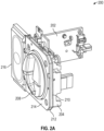
- FIGS. 2A and 2B each shows skimmer detection device 200 consistent with at least one example of this disclosure.
- Skimmer detection device 200 may include driver board 202, a mounting bracket 204, channel molding 206, a bezel 208, a media enhanced entry indicator board 210, a diffuser 212, an overlay detection board 214, and a contactless card reader 216.
- Driver board 202 may include a processor and memory, such as processor 102 and memory unit 104, that can control skimmer detection device 200.
- driver board 202 may receive instructions from processor 102 and data from memory unit 104 to carryout skimmer detection as disclosed herein.
- driver board 202 may include a separate processor and memory unit to carry out skimmer detection as disclosed herein and transmit skimmer detection and/or faults to processor 102.
- Mounting bracket 204 may be used to mount skimmer detection device 200 in self-service terminal 100.
- the various components of skimmer detection device 200 may be mounted to mounting bracket 204.
- Channel molding 206 may allow for routing cables, such as co-ax cables used to connect sensors to driver board 202.
- Bezel 208 may include electronic components that allow a user to physically swipe a card and/or insert a card into self-service terminal 100. As disclosed herein, bezel 208 may include lights, such as LEDs and/or sensors that are used to detect skimming devices.
- Media enhanced entry indicator board 210 may include lights, such as LEDs 218 and 220.
- Media enhanced entry indicator board 210 may display lights in various patterns to convey information to a user. For example, media enhanced entry indicator board 210 may illuminate LED 218 when a user inserts his or her card and may illuminate LED 220 as an indication that the user should remove his or her card from bezel 208.
- Diffuser 212 may be a device that is used to secure bezel 208 to mounting bracket 204. Diffuser 212 may allow for routing of cables, wires, etc. Diffuser 212 may also provide mounting options and/or provided portion for media enhanced entry indicator board 210 and/or LEDs 218 and 220.
- Overlay detection board 214 may be mounted to diffuser 212.
- Overlay detection board 214 may include sensors as disclosed herein that allow for the detection of devices, such as skimmers, that are overlaid onto bezel 208, contactless card reader 216, and/or otherwise located proximate bezel 208 and/or contactless card reader 216 to skim card information.
- FIGS. 3A through 3L each shows a sensor pattern applied to overlay detection board 214 consistent with at least one example of this disclosure.
- various electrodes 302, 304, 306, 308, and 310 can be integrated into overlay detection board 214.
- electrodes 302, 304, 306, 308, and 310 can be activated in various patterns to detect the presence of skimmers.
- Table 1 illustrates example sensor patterns shown in corresponding FIGS. 3A through 3L .
- the sensor patterns can include various combinations of transmit (TX) and receive (RX) electrodes that enable capacitance measurements to be collected.
- Table 1 also indicated example connections for the various electrodes with general purpose input/output (GPIO) connection on driver board 202.
- TX transmit
- RX receive
- Contactless card reader 216 may be a contactless reader, such as contactless reader 118 described herein. Contactless reader 216 may be attached to mounting bracket 204 as shown in FIGS. 2A and 2B or may be located separately from skimmer detection device 200. When located separately from skimmer detection device 200, cables, wires, etc. may be used to connect any sensors, electrodes, etc. that may be located proximate contactless card reader 216 for detection of skimmers and/or other tampering with contactless card reader 216.
- FIG. 4 shows a method 400 for detecting a skimmer device consistent with at least one example of this disclosure.
- Method 400 may begin at stage 402 where a baseline measurement for a plurality of sensors located proximate the card reader may be obtained.
- the baseline measurement may be an initial baseline that is set at a factory during fabrication of a self-service terminal under controlled conditions.
- obtaining the baseline measurement may include receiving the baseline measurement from a memory of the self-service terminal or a memory and/or a memory of a driver board.
- the baseline measurement may be obtained during operation of the self-service terminal, such as by updated an initial baseline due to changes in environmental conditions.
- obtaining the baseline measurement may include receiving a signal from sensors located proximate card readers at regular intervals.
- the signals may correspond to measurements, such as capacitance vales.
- the signal from each of the sensors may represent the baseline measurement and may be saved as a new baseline.
- the signals to constitute a new baseline it is presumed that the deviation in the newly received signal does not deviate from a previous received signal or previously received number of signals, such as for example, the previous 10 signals received.
- the change in signal values such as capacitance measurement may be restricted to a preset deviation over a predetermined time, predetermined number of samples, etc. to reduce the likelihood that a skimmer can installed and mistaken as a weather related change in measured values.
- method 400 may proceed to stage 402 wherein one or more sensors may be activated.
- the various sensors may be activated such that one, all, or any subset of the sensors are activated to obtain measurement values.
- the pattern in which sensors are activated may be preprogrammed into a number of patterns, such as the patterns shown in FIGS. 3A through 3L .
- the various patterns can be sampled in a round robin manner as shown in FIG. 5 .
- FIG. 5 shows various patterns 502A through 502L (collectively patterns 502) as detailed in Table 1. During round robin sampling each of patterns 502 can be sampled successively to obtain measured capacitance values.
- each of patterns 502 may correspond to different test patterns.
- a signal from each of sensor activated may be received (406).
- the received signals may be voltages, currents, or other electrical signals.
- a processor such as processor 102 may convert the signals to a measurement, such as a capacitance measurement using lookup tables and/or calibration equations that may be stored in and retrieved from a memory, such as memory unit 204 as part of self-service terminal data 108.
- the various signals and/or measurements may generate noise due to temporary contact from a user's fingers and/or rain contacting a card reader and/or sensor. Because the deviations in signals and/or measurements may be temporary due to the temporary nature of the contact, they may generate noise that can be filtered. Filtering the signals or measurements may be done using filtering circuity, such a high, low, and bandpass filters.
- Software may also be included as part of software module 106 and/or self-service data 108 that can implement filtering algorithms such as Fourier transforms, infinite impulse response (IRR) or finite impulse response (FIR) discrete-time and/or digital filters, etc.
- a determination may be made that a skimmer is located proximate the card reader (410). For example, when the signals and/or measurements form one or more, possibly each, of a subset of the sensors deviates from the baseline measurement by a predetermined threshold a determination may be made that a skimmer is located proximate the card reader.
- the predetermined threshold can be a preset value, such as a multiple of standard deviations from the baseline measurement.
- the deviations can be for a time period greater than a preset time period.
- the deviations from the baseline may be 10, 20, 30, 40, 50, 60, 70, 80, etc. standard deviations for a time period exceeding 10, 20, 30, 40, 50, 60, 80, 120, etc. seconds.
- More than one pattern may be used to confirm detection of a skimmer.
- pattern 1 may indicate the presence of a skimmer, but none of the other patterns may indicate a detection of a skimmer.
- a predetermined number of patterns such as say 3, 5, a majority of the patterns, etc., may be required to indicate the presence of a skimmer before an alter is generated (412) and/or the card reader and/or self-service terminal is disabled (414).
- an alter message may be generated (412).
- the alert message may be transmitted to service and/or security personnel for review and action. For example, for an ATM that is connected to a bank, the alert message may prompt a bank employee to quickly check the ATM for the tampering and/or the presence of a skimmer. If one is located the employee can quickly remove the device before customer data is compromised.
- the self-service terminal may be disabled (414).
- Disabling the self-service terminal may include disabling the card reader that a user physical inserts his or her card into while leaving a contactless card reader operational to allow for limited use of the self-service terminal until an inspection can be performed.
- Disabling the self-service terminal may also include completely disabling all card readers and displaying an out of service message on a display to notify users the self-service terminal is unavailable for use.
- an alert message may be transmitted (412) after a self-service terminal is disabled (414).
- the filtering of noise (408) may be omitted.
- Example 1 is a method for detecting a skimmer located proximate a card reader of a self-service terminal (SST), the method comprising: obtaining a baseline measurement for a plurality of sensors located proximate the card reader; activating a subset of the plurality of sensors; receiving a signal from each of the subset of the plurality of sensors that were activated; determining that the skimmer is located proximate the card reader when the signal from each of the subset of the plurality of sensors deviates from the baseline measurement by a predetermined threshold; and disabling the self-service terminal in response to determining that the skimmer is located proximate the card reader.
- SST self-service terminal
- Example 2 the subject matter of Example 1 optionally includes wherein obtaining the baseline measurement comprises receiving the baseline measurement from a memory of the self-service terminal.
- Example 3 the subject matter of any one or more of Examples 1-2 optionally include wherein obtaining the baseline measurement comprises receiving a signal from each of the sensors, the signal from each of the sensors representing the baseline measurement.
- Example 4 the subject matter of any one or more of Examples 1-3 optionally include wherein the baseline measurement comprises a capacitance value for each of the plurality of sensors.
- Example 5 the subject matter of any one or more of Examples 1-4 optionally include wherein the predetermined threshold comprises a change in a capacitance measure over a predetermined time.
- Example 6 the subject matter of any one or more of Examples 1-5 optionally include wherein activating the subset of the plurality of sensors comprises activating the subset of the plurality in a round robin manner.
- Example 7 the subject matter of any one or more of Examples 1-6 optionally include wherein disabling the self-service terminal comprise disabling the card reader.
- Example 8 the subject matter of any one or more of Examples 1-7 optionally include transmitting an alert message.
- Example 9 the subject matter of any one or more of Examples 1-8 optionally include filtering noise from the signal received from each of the subset of the plurality of sensors.
- Example 10 the subject matter of any one or more of Examples 1-9 optionally include wherein the subset of the plurality of sensors is one of a plurality of subsets of the sensors, each of the plurality of subsets of corresponding to a different test pattern.
- Example 11 is a skimmer detection system comprising: a processor; and a memory storing instructions that, when executed by the processor, causes the processor to perform actions comprising: obtaining a baseline measurement for a plurality of sensors located proximate a card reader of a self-service terminal; activating a subset of the plurality of sensors; receiving a signal from each of the subset of the plurality of sensors that were activated; determining that a skimmer is located proximate the card reader when the signal from each of the subset of the plurality of sensors deviates from the baseline measurement by a predetermined threshold; and disabling the self-service terminal in response to determining that the skimmer is located proximate the card reader.
- Example 12 the subject matter of Example 11 optionally includes wherein the baseline measurement comprises a capacitance value for each of the plurality of sensors.
- Example 13 the subject matter of any one or more of Examples 11-12 optionally include wherein the predetermined threshold comprises a change in a capacitance measure over a predetermined time.
- Example 14 the subject matter of any one or more of Examples 11-13 optionally include wherein activating the subset of the plurality of sensors comprises activating the subset of the plurality in a round robin manner.
- Example 15 the subject matter of any one or more of Examples 11-14 optionally include transmitting an alert message.
- Example 16 the subject matter of any one or more of Examples 11-15 optionally include filtering noise from the signal received from each of the subset of the plurality of sensors.
- Example 17 is a self-service terminal (SST) comprising: a card reader; a plurality of sensors located proximate the card reader; a processor in electrical communication with the plurality of sensors; and a memory storing instructions that, when executed by the processor, causes the processor to perform actions comprising: receive a baseline measurement for the plurality of sensors from the memory; activating a subset of the plurality of sensors; receiving a signal from each of the subset of the plurality of sensors that were activated; determining that a skimmer is located proximate the card reader when the signal from each of the subset of the plurality of sensors deviates from the baseline measurement by a predetermined threshold over a predetermined time; and disabling the self-service terminal and transmitting an alert message in response to determining that the skimmer is located proximate the card reader.
- SST self-service terminal
- Example 18 the subject matter of Example 17 optionally includes wherein the plurality of sensors comprises a plurality of capacitance sensors and the baseline measurement comprises a capacitance value for each of the plurality of capacitance sensors.
- Example 19 the subject matter of any one or more of Examples 17-18 optionally include wherein activating the subset of the plurality of sensors comprises activating the subset of the plurality in a round robin manner.
- Example 20 the subject matter of any one or more of Examples 17-19 optionally include filtering noise from the signal received from each of the subset of the plurality of sensors.
- Example 21 the apparatuses or method of any one or any combination of Examples 1 - 20 can optionally be configured such that all elements or options recited are available to use or select from.
Landscapes
- Business, Economics & Management (AREA)
- Physics & Mathematics (AREA)
- Accounting & Taxation (AREA)
- General Physics & Mathematics (AREA)
- Finance (AREA)
- Engineering & Computer Science (AREA)
- Theoretical Computer Science (AREA)
- Health & Medical Sciences (AREA)
- Toxicology (AREA)
- General Business, Economics & Management (AREA)
- Strategic Management (AREA)
- Computer Security & Cryptography (AREA)
- General Engineering & Computer Science (AREA)
- Electromagnetism (AREA)
- General Health & Medical Sciences (AREA)
- Artificial Intelligence (AREA)
- Computer Vision & Pattern Recognition (AREA)
- Alarm Systems (AREA)
- Measurement And Recording Of Electrical Phenomena And Electrical Characteristics Of The Living Body (AREA)
Abstract
Description
- Disclosed are systems and methods for detecting a skimmer located proximate a card reader of a self-service terminal (SST). The systems and methods may include obtaining a baseline measurement for a plurality of sensors located proximate the card reader and activating a subset of the plurality of sensors. A signal may be received from each of the subset of the plurality of sensors that were activated. When the signal from each of the subset of the plurality of sensors deviate from the baseline measurement by a predetermined threshold, a determination may be made that the skimmer is proximate the card reader. In response to determining that the skimmer is located proximate the card reader, the self-service terminal may be disabled.
- According to a first aspect of the present invention, there is provided a method for detecting a skimmer located proximate a card reader of a self-service terminal (SST), the method comprising:
- obtaining a baseline measurement for a plurality of sensors located proximate the card reader;
- activating a subset of the plurality of sensors;
- receiving a signal from each of the subset of the plurality of sensors that were activated;
- determining that the skimmer is located proximate the card reader when the signal from each of the subset of the plurality of sensors deviates from the baseline measurement by a predetermined threshold; and
- disabling the self-service terminal in response to determining that the skimmer is located proximate the card reader.
- In certain embodiments, obtaining the baseline measurement comprises receiving the baseline measurement from a memory of the self-service terminal.
- In certain embodiments, obtaining the baseline measurement comprises receiving a signal from each of the sensors, the signal from each of the sensors representing the baseline measurement.
- In certain embodiments, the baseline measurement comprises a capacitance value for each of the plurality of sensors.
- In certain embodiments, the predetermined threshold comprises a change in a capacitance measure over a predetermined time.
- In certain embodiments, activating the subset of the plurality of sensors comprises activating the subset of the plurality in a round robin manner.
- In certain embodiments, disabling the self-service terminal comprises disabling the card reader.
- In certain embodiments, the method further comprises transmitting an alert message.
- In certain embodiments, the method further comprises filtering noise from the signal received from each of the subset of the plurality of sensors.
- In certain embodiments, the subset of the plurality of sensors is one of a plurality of subsets of the sensors, each of the plurality of subsets of corresponding to a different test pattern.
- According to a second aspect of the present invention, there is provided a skimmer detection system comprising:
- a processor; and
- a memory storing instructions that, when executed by the processor, causes the processor to perform actions comprising:
- obtaining a baseline measurement for a plurality of sensors located proximate a card reader of a self-service terminal;
- activating a subset of the plurality of sensors;
- receiving a signal from each of the subset of the plurality of sensors that were activated;
- determining that a skimmer is located proximate the card reader when the signal from each of the subset of the plurality of sensors deviates from the baseline measurement by a predetermined threshold; and
- disabling the self-service terminal in response to determining that the skimmer is located proximate the card reader.
- In certain embodiments, the baseline measurement comprises a capacitance value for each of the plurality of sensors.
- In certain embodiments, the predetermined threshold comprises a change in a capacitance measure over a predetermined time.
- In certain embodiments, activating the subset of the plurality of sensors comprises activating the subset of the plurality in a round robin manner.
- In certain embodiments, the skimmer detection system further comprises transmitting an alert message.
- In certain embodiments, the skimmer detection system further comprises filtering noise from the signal received from each of the subset of the plurality of sensors.
- According to a third aspect of the present invention, there is provided a self-service terminal (SST) comprising:
- a card reader;
- a plurality of sensors located proximate the card reader;
- a processor in electrical communication with the plurality of sensors; and
- a memory storing instructions that, when executed by the processor, causes the processor to perform actions comprising:
- receive a baseline measurement for the plurality of sensors from the memory; activating a subset of the plurality of sensors;
- receiving a signal from each of the subset of the plurality of sensors that were activated;
- determining that a skimmer is located proximate the card reader when the signal from each of the subset of the plurality of sensors deviates from the baseline measurement by a predetermined threshold over a predetermined time; and
- disabling the self-service terminal and transmitting an alert message in response to determining that the skimmer is located proximate the card reader.
- In certain embodiments, the plurality of sensors comprises a plurality of capacitance sensors and the baseline measurement comprises a capacitance value for each of the plurality of capacitance sensors.
- In certain embodiments, activating the subset of the plurality of sensors comprises activating the subset of the plurality in a round robin manner.
- In certain embodiments, the self-service terminal further comprises filtering noise from the signal received from each of the subset of the plurality of sensors.
- In the drawings, which are not necessarily drawn to scale, like numerals can describe similar components in different views. Like numerals having different letter suffixes can represent different instances of similar components. The drawings illustrate generally, by way of example, but not by way of limitation, various embodiments discussed in the present document.
-
FIG. 1 shows an example schematic of a self-service terminal consistent with at least one example of this disclosure. -
FIGS. 2A and2B each shows an example skimmer detection component of a self-service terminal consistent with at least one example of this disclosure. -
FIGS. 3A through 3L each shows a sensor pattern consistent with at least one example of this disclosure. -
FIG. 4 shows an example method consistent with at least one example of this disclosure. -
FIG. 5 shows an example of a round robin sampling of various sensor patterns consistent with at least one example of this disclosure. - Corresponding reference characters indicate corresponding parts throughout the several views. The exemplifications set out herein illustrate exemplary embodiments of the disclosure, and such exemplifications are not to be construed as limiting the scope of the disclosure any manner.
- Disclosed herein are systems and methods for protection against skimming devices being placed on self-service terminals (SSTs). Skimming devices are used by criminals to steal card information when unsuspecting users swipe their cards. The skimming devices read the information from the magnetic strip on cards as users swipe their cards. The criminals can then use the information to make duplicate cards, make fraudulent online purchases, and/or sell the information on the dark web.
- The systems and methods disclosed herein may allow for detection of a skimming device, sometimes called a skimmer, that is place on or proximate a card reader of SSTs. As disclosed herein, software, sometimes referred to as a "driver" may command firmware to sample one or more sensors, sometimes referred to as a "pattern." The pattern may be a subset of a plurality of sensors. For example, if there are seven sensors, the pattern selected may be every odd sensor, every even sensor, two sensors located directly across from one another, or any other combination of sensors. The various patterns can be preprogrammed patterns and/or patterns generated at random.
- The driver can select and/or generate a pattern to be sampled by commanding the firmware. As a non-limiting example, a round robin approach can be implemented to sample data for each pattern on a regular basis. For instance, a variety of preprogrammed patterns may be programmed into the driver and/or firmware. Upon execution, the driver may command the firmware to sample the various patterns in a round robin fashion.
- The firmware may sample the pattern and report the sampled data to the driver. The driver may then process the sampled pattern. The raw data from each of the sampled patterns may be processed to yield an average value (level) for that round.
- A calibration event, under supervised control, may be used to create an averaged level, sometimes referred to as a baseline or default baseline, for each sensor and/or pattern. A second baseline, sometimes referred to as an active baseline, may be set equal to default baseline. Due to environmental changes, especially temperature, the level drift away from the active baseline and hence the active baseline is updated continuously. For example, every ten minutes the default baseline may be set to the active baseline value. Thus, during the day when temperatures change, the baseline value may be updated to account for natural and/or expected environmental changes that may occur. As disclosed herein, the active baseline may be tracked so long as there is no skimmer detected, rain compensation is not activated, and/or the signal is below a fixed rain stability. Until a new default baseline calibration event, the level for each sensor and/or pattern may be measured against the active baseline for that sensor and/or pattern.
- A noisy level may occur due to consumer activity and/or rain. Therefore, each sensor and/or pattern stability may be measured. For example, the stability may be a standard deviation of 80 samples of the baseline level in current use. Active baseline trend and level analysis may be adjusted to accommodate the noise, such as small deviations that may be caused by rain.
- As disclosed herein, for each round and/or for each pattern within that round the level and stability may be checked. If the stability is less than a preset value, such as for example, 50 standard deviations, then the level may be checked. If the level is greater than the default baseline +/- X deviations, then a possible skimmer is registered. If after a predetermined number of rounds, such as for example five successive rounds, the number of patterns registering a skimmer equates to a preset number, sometimes referred to as a depth, such as for example three successive rounds in five successive rounds, then an unusual object alert can be reported. The unusual object may be a skimmer.
- If stability is greater than rain stability, then the pattern may be noisy and possible rain is registered. If after a preset number of rounds such as five rounds, the number of patterns registering rain, sometimes referred to as a depth, equates to a preset number, such as four of five rounds, then the rain may be reported. After reporting, service personnel can check weather data to confirm the presence of rain. If rain is detected by the service personnel, no action is needed. However, if rain is not detected by the service personnel, then a service call can be initiated.
- If there has been card activity during the round robin sampling, then the rain detect can reset to round zero. If there is a card in the reader, then no skimmer may be reported until there is no card in the reader.
- There are sensors on SSTs that can provide inputs to controllers of the SSTs and the inputs may indicate that a door or fascia covers have been opened, further indicating that a servicing action (e.g., replacing currency cassettes, performance of routine maintenance, etc.) may be in progress. When these inputs return the doors and/or facias have been closed and/or are in a home position, a period of settlement may occur in which there is no reporting of a skimmer. This settlement period may allow for the system to settle especially during period of excessive cold or heat.
- Faults may be reported indicating a problem with an individual pattern and/or a problem with the device; the SST in general and/or the specific hardware used to implement skimmer detection. For example, excessive stability readings and/or abnormal level from a particular sensor and/or pattern that relies on a particular sensor may indicate a fault with the particular sensor.
- For skimmer and rain reporting the depth and deviation inputs may be varied with preset values. This may allow users to modify the decision and reporting behavior. Alerts and faults may be reported through the SST channels. For example, alerts and faults may be reported through automated teller machine (ATM) transaction and servicing channels.
- The above discussion is intended to provide an overview of subject matter of the present patent application. It is not intended to provide an exclusive or exhaustive explanation of the invention. The description below is included to provide further information about the present patent application.
- Turning now to the figures,
FIG. 1 shows an example schematic of self-service terminal 100. Non-limiting examples of self-service terminal 100 may include self-checkout registers found in brick-and-mortar stores, pumps at gas stations, automated teller machines, self-service kiosks, and any other terminal that may require a user to scan or swipe a card, such as a credit card or debit card to complete a transaction. As shown inFIG. 1 , self-service terminal 100 may include aprocessor 102 and amemory 104.Memory 104 may include asoftware module 106 and self-service terminal data 108. While executing onprocessor 104,software module 106 may perform processes for detecting skimming devices, including, for example, one or more stages included in amethod 400 described below with respect toFIG. 4 . Self-service terminal 100 also may include auser interface 110, acommunications port 112, and an input/output (I/O)device 114. - I/
O device 114 may include acard reader 116 and acontactless card reader 118.Card reader 116 may be a card reader that requires a user to physical swipe a card in order to enter information stored in a magnetic strip of the card into the self-service terminal.Contactless card reader 118 may be a card reader that extracts information from a card when the card is placed in close proximity tocontactless card reader 118. The card information may be transmitted to self-service terminal 100 via short range wireless communications. For example,contactless card reader 118 may be connected tocommunications port 112 and allow for near field communications, BLUETOOTH® communications, etc. between the users' card and self-service terminal 100. - As disclosed herein,
software module 106 may include instructions that when executed byprocessor 102 that cause self-service terminal 100 to retrieve user information from remotes systems once a user has entered card information viacard readers 116 and/or 118. For example, once a user has been authenticated, such as by swiping his or her card viacard reader 118 and entering a personal identification number (PIN) viauser interface 110, self-service terminal 100 may retrieve account balances, daily withdrawal limits, etc. from a central computer maintained by a financial institution. -
Software module 106 may also retrieve and/or store self-service terminal data 108. For example, during sampling of sensors locatedproximate card readers software module 106 may retrieve active baselines, permissible standard deviation tolerances, patterns, etc. from self-service terminal data 108. During operations,software module 106 may write new self-service terminal data 108, such as, but not limited to, writing updated active baselines as disclosed herein. Non-limiting examples of self-service terminal data 108 may include active baseline data, preset values for deviations from active baselines, error and/or fault codes, routing instructions for routing the error and/or fault codes, actions to take, such as disabling one or both ofcard readers service terminal 100 in the event of an error and/or fault event detection, etc. -
User interface 110 can include any number of devices that allow a user to interface with self-service terminal 100. Non-limiting examples ofuser interface 110 include a keypad, a microphone, a display (touchscreen or otherwise), etc. User interface may also operate as an I/O device, such as I/O device 114. For example, user interface may be a touch screen display that displays instructions for a user an accepts inputs from the user via the user touching appropriate buttons displayed onuser interface 110. -
Communications port 112 may allow self-service terminal 100 to communicate with various information sources and devices, such as, but not limited to, remote computing devices such as servers or other remote computers maintained by financial institutions, mobile devices such as a user's smart phone, peripheral devices, etc. Non-limiting examples ofcommunications port 112 include, Ethernet cards (wireless or wired), BLUETOOTH® transmitters and receivers, near-field communications modules, etc. - I/
O device 114 may allow self-service terminal 100 to receive and output information. Non-limiting examples of I/O device 114 may includecard readers FIGS. 2A and2B ),user interface 110, sensors, such as accelerometers, thermistors, thermocouples, etc. for measuring temperature and/or motion, a camera (still or video), fingerprint or other biometric scanners, scales for weighing products, etc. -
FIGS. 2A and2B each showsskimmer detection device 200 consistent with at least one example of this disclosure.Skimmer detection device 200 may includedriver board 202, a mountingbracket 204,channel molding 206, abezel 208, a media enhancedentry indicator board 210, adiffuser 212, anoverlay detection board 214, and acontactless card reader 216. -
Driver board 202 may include a processor and memory, such asprocessor 102 andmemory unit 104, that can controlskimmer detection device 200. For example,driver board 202 may receive instructions fromprocessor 102 and data frommemory unit 104 to carryout skimmer detection as disclosed herein. In addition,driver board 202 may include a separate processor and memory unit to carry out skimmer detection as disclosed herein and transmit skimmer detection and/or faults toprocessor 102. - Mounting
bracket 204 may be used to mountskimmer detection device 200 in self-service terminal 100. In addition, the various components ofskimmer detection device 200 may be mounted to mountingbracket 204.Channel molding 206 may allow for routing cables, such as co-ax cables used to connect sensors todriver board 202. -
Bezel 208 may include electronic components that allow a user to physically swipe a card and/or insert a card into self-service terminal 100. As disclosed herein,bezel 208 may include lights, such as LEDs and/or sensors that are used to detect skimming devices. - Media enhanced
entry indicator board 210 may include lights, such asLEDs entry indicator board 210 may display lights in various patterns to convey information to a user. For example, media enhancedentry indicator board 210 may illuminateLED 218 when a user inserts his or her card and may illuminateLED 220 as an indication that the user should remove his or her card frombezel 208. -
Diffuser 212 may be a device that is used to securebezel 208 to mountingbracket 204.Diffuser 212 may allow for routing of cables, wires, etc.Diffuser 212 may also provide mounting options and/or provided portion for media enhancedentry indicator board 210 and/orLEDs -
Overlay detection board 214 may be mounted todiffuser 212.Overlay detection board 214 may include sensors as disclosed herein that allow for the detection of devices, such as skimmers, that are overlaid ontobezel 208,contactless card reader 216, and/or otherwise locatedproximate bezel 208 and/orcontactless card reader 216 to skim card information. -
FIGS. 3A through 3L each shows a sensor pattern applied tooverlay detection board 214 consistent with at least one example of this disclosure. As shown inFIGS. 3A through 3L , various electrodes 302, 304, 306, 308, and 310 can be integrated intooverlay detection board 214. During operation, electrodes 302, 304, 306, 308, and 310 can be activated in various patterns to detect the presence of skimmers. Table 1 illustrates example sensor patterns shown in correspondingFIGS. 3A through 3L . As indicated the sensor patterns can include various combinations of transmit (TX) and receive (RX) electrodes that enable capacitance measurements to be collected. Table 1 also indicated example connections for the various electrodes with general purpose input/output (GPIO) connection ondriver board 202.Table 1: Channel Pattern Selection & GPIO Connections RX0 RX1 RX2 TX3 TX2 TX1 TX0 Pattern (FIG.) 0 0 1 0 0 0 0 3A 0 1 0 0 0 0 0 3B 1 0 0 0 0 0 0 3C 0 0 1 0 0 1 1 3D 0 1 0 0 0 1 1 3E 1 0 0 0 0 1 1 3F 0 0 1 1 1 0 0 3G 0 1 0 1 1 0 0 3H 1 0 0 1 1 0 0 31 0 0 1 1 1 1 1 3J 0 1 0 1 1 1 1 3K 1 0 0 1 1 1 1 3L -
Contactless card reader 216 may be a contactless reader, such ascontactless reader 118 described herein.Contactless reader 216 may be attached to mountingbracket 204 as shown inFIGS. 2A and2B or may be located separately fromskimmer detection device 200. When located separately fromskimmer detection device 200, cables, wires, etc. may be used to connect any sensors, electrodes, etc. that may be located proximatecontactless card reader 216 for detection of skimmers and/or other tampering withcontactless card reader 216. -
FIG. 4 shows amethod 400 for detecting a skimmer device consistent with at least one example of this disclosure.Method 400 may begin atstage 402 where a baseline measurement for a plurality of sensors located proximate the card reader may be obtained. As disclosed herein, the baseline measurement may be an initial baseline that is set at a factory during fabrication of a self-service terminal under controlled conditions. As such, obtaining the baseline measurement may include receiving the baseline measurement from a memory of the self-service terminal or a memory and/or a memory of a driver board. - Also as disclosed herein, the baseline measurement may be obtained during operation of the self-service terminal, such as by updated an initial baseline due to changes in environmental conditions. For example, obtaining the baseline measurement may include receiving a signal from sensors located proximate card readers at regular intervals. The signals may correspond to measurements, such as capacitance vales. Thus, the signal from each of the sensors may represent the baseline measurement and may be saved as a new baseline. For the signals to constitute a new baseline it is presumed that the deviation in the newly received signal does not deviate from a previous received signal or previously received number of signals, such as for example, the previous 10 signals received. By limiting the deviation in the new signal large changes in signal value that may be indicative of a skimmer being placed proximate a card reader are not mistakenly saved as a new baseline. Stated another way, the change in signal values, such as capacitance measurement may be restricted to a preset deviation over a predetermined time, predetermined number of samples, etc. to reduce the likelihood that a skimmer can installed and mistaken as a weather related change in measured values.
- Once the baseline is received or established,
method 400 may proceed to stage 402 wherein one or more sensors may be activated. For example, the various sensors may be activated such that one, all, or any subset of the sensors are activated to obtain measurement values. The pattern in which sensors are activated may be preprogrammed into a number of patterns, such as the patterns shown inFIGS. 3A through 3L . The various patterns can be sampled in a round robin manner as shown inFIG. 5 . For example,FIG. 5 showsvarious patterns 502A through 502L (collectively patterns 502) as detailed in Table 1. During round robin sampling each of patterns 502 can be sampled successively to obtain measured capacitance values. As disclosed herein, each of patterns 502 may correspond to different test patterns. By having differenttest patterns method 400 and the various systems disclosed herein may detect different skimmer configurations and/or skimmers placed in different locations proximateskimmer detection device 200. - After activating one or more sensors, a signal from each of sensor activated, sometimes referred to as a subset of the plurality of sensors that were activated, may be received (406). The received signals may be voltages, currents, or other electrical signals. A processor, such as
processor 102 may convert the signals to a measurement, such as a capacitance measurement using lookup tables and/or calibration equations that may be stored in and retrieved from a memory, such asmemory unit 204 as part of self-service terminal data 108. - Prior to converting the signals to a measure and/or after converting the signals to a measurement noise maybe filtered from the signals and/or measurements (408). For example, during rain or while a user is using the self-service terminal, the various signals and/or measurements may generate noise due to temporary contact from a user's fingers and/or rain contacting a card reader and/or sensor. Because the deviations in signals and/or measurements may be temporary due to the temporary nature of the contact, they may generate noise that can be filtered. Filtering the signals or measurements may be done using filtering circuity, such a high, low, and bandpass filters. Software may also be included as part of
software module 106 and/or self-service data 108 that can implement filtering algorithms such as Fourier transforms, infinite impulse response (IRR) or finite impulse response (FIR) discrete-time and/or digital filters, etc. - Using the received signals and/or measurements, a determination may be made that a skimmer is located proximate the card reader (410). For example, when the signals and/or measurements form one or more, possibly each, of a subset of the sensors deviates from the baseline measurement by a predetermined threshold a determination may be made that a skimmer is located proximate the card reader. The predetermined threshold can be a preset value, such as a multiple of standard deviations from the baseline measurement. The deviations can be for a time period greater than a preset time period. For example, the deviations from the baseline may be 10, 20, 30, 40, 50, 60, 70, 80, etc. standard deviations for a time period exceeding 10, 20, 30, 40, 50, 60, 80, 120, etc. seconds.
- More than one pattern may be used to confirm detection of a skimmer. For example,
pattern 1 may indicate the presence of a skimmer, but none of the other patterns may indicate a detection of a skimmer. To avoid false positives, before a determination that a skimmer is present a predetermined number of patterns, such assay - Once a skimmer is detected, an alter message may be generated (412). The alert message may be transmitted to service and/or security personnel for review and action. For example, for an ATM that is connected to a bank, the alert message may prompt a bank employee to quickly check the ATM for the tampering and/or the presence of a skimmer. If one is located the employee can quickly remove the device before customer data is compromised.
- If the self-service terminal is not attached to a bank or readily accessible by service personnel, then the self-service terminal may be disabled (414). Disabling the self-service terminal may include disabling the card reader that a user physical inserts his or her card into while leaving a contactless card reader operational to allow for limited use of the self-service terminal until an inspection can be performed. Disabling the self-service terminal may also include completely disabling all card readers and displaying an out of service message on a display to notify users the self-service terminal is unavailable for use.
- As disclosed herein various stages of
method 400 may be rearranged and/or omitted without departing from the scope of this disclosure. For example, an alert message may be transmitted (412) after a self-service terminal is disabled (414). The filtering of noise (408) may be omitted. - The following, non-limiting examples, detail certain aspects of the present subject matter to solve the challenges and provide the benefits discussed herein, among others.
- Example 1 is a method for detecting a skimmer located proximate a card reader of a self-service terminal (SST), the method comprising: obtaining a baseline measurement for a plurality of sensors located proximate the card reader; activating a subset of the plurality of sensors; receiving a signal from each of the subset of the plurality of sensors that were activated; determining that the skimmer is located proximate the card reader when the signal from each of the subset of the plurality of sensors deviates from the baseline measurement by a predetermined threshold; and disabling the self-service terminal in response to determining that the skimmer is located proximate the card reader.
- In Example 2, the subject matter of Example 1 optionally includes wherein obtaining the baseline measurement comprises receiving the baseline measurement from a memory of the self-service terminal.
- In Example 3, the subject matter of any one or more of Examples 1-2 optionally include wherein obtaining the baseline measurement comprises receiving a signal from each of the sensors, the signal from each of the sensors representing the baseline measurement.
- In Example 4, the subject matter of any one or more of Examples 1-3 optionally include wherein the baseline measurement comprises a capacitance value for each of the plurality of sensors.
- In Example 5, the subject matter of any one or more of Examples 1-4 optionally include wherein the predetermined threshold comprises a change in a capacitance measure over a predetermined time.
- In Example 6, the subject matter of any one or more of Examples 1-5 optionally include wherein activating the subset of the plurality of sensors comprises activating the subset of the plurality in a round robin manner.
- In Example 7, the subject matter of any one or more of Examples 1-6 optionally include wherein disabling the self-service terminal comprise disabling the card reader.
- In Example 8, the subject matter of any one or more of Examples 1-7 optionally include transmitting an alert message.
- In Example 9, the subject matter of any one or more of Examples 1-8 optionally include filtering noise from the signal received from each of the subset of the plurality of sensors.
- In Example 10, the subject matter of any one or more of Examples 1-9 optionally include wherein the subset of the plurality of sensors is one of a plurality of subsets of the sensors, each of the plurality of subsets of corresponding to a different test pattern.
- Example 11 is a skimmer detection system comprising: a processor; and a memory storing instructions that, when executed by the processor, causes the processor to perform actions comprising: obtaining a baseline measurement for a plurality of sensors located proximate a card reader of a self-service terminal; activating a subset of the plurality of sensors; receiving a signal from each of the subset of the plurality of sensors that were activated; determining that a skimmer is located proximate the card reader when the signal from each of the subset of the plurality of sensors deviates from the baseline measurement by a predetermined threshold; and disabling the self-service terminal in response to determining that the skimmer is located proximate the card reader.
- In Example 12, the subject matter of Example 11 optionally includes wherein the baseline measurement comprises a capacitance value for each of the plurality of sensors.
- In Example 13, the subject matter of any one or more of Examples 11-12 optionally include wherein the predetermined threshold comprises a change in a capacitance measure over a predetermined time.
- In Example 14, the subject matter of any one or more of Examples 11-13 optionally include wherein activating the subset of the plurality of sensors comprises activating the subset of the plurality in a round robin manner.
- In Example 15, the subject matter of any one or more of Examples 11-14 optionally include transmitting an alert message.
- In Example 16, the subject matter of any one or more of Examples 11-15 optionally include filtering noise from the signal received from each of the subset of the plurality of sensors.
- Example 17 is a self-service terminal (SST) comprising: a card reader; a plurality of sensors located proximate the card reader; a processor in electrical communication with the plurality of sensors; and a memory storing instructions that, when executed by the processor, causes the processor to perform actions comprising: receive a baseline measurement for the plurality of sensors from the memory; activating a subset of the plurality of sensors; receiving a signal from each of the subset of the plurality of sensors that were activated; determining that a skimmer is located proximate the card reader when the signal from each of the subset of the plurality of sensors deviates from the baseline measurement by a predetermined threshold over a predetermined time; and disabling the self-service terminal and transmitting an alert message in response to determining that the skimmer is located proximate the card reader.
- In Example 18, the subject matter of Example 17 optionally includes wherein the plurality of sensors comprises a plurality of capacitance sensors and the baseline measurement comprises a capacitance value for each of the plurality of capacitance sensors.
- In Example 19, the subject matter of any one or more of Examples 17-18 optionally include wherein activating the subset of the plurality of sensors comprises activating the subset of the plurality in a round robin manner.
- In Example 20, the subject matter of any one or more of Examples 17-19 optionally include filtering noise from the signal received from each of the subset of the plurality of sensors.
- In Example 21, the apparatuses or method of any one or any combination of Examples 1 - 20 can optionally be configured such that all elements or options recited are available to use or select from.
- The above detailed description includes references to the accompanying drawings, which form a part of the detailed description. The drawings show, by way of illustration, specific embodiments in which the invention can be practiced. These embodiments are also referred to herein as "examples." Such examples can include elements in addition to those shown or described. However, the present inventors also contemplate examples in which only those elements shown or described are provided. Moreover, the present inventors also contemplate examples using any combination or permutation of those elements shown or described (or one or more aspects thereof), either with respect to a particular example (or one or more aspects thereof), or with respect to other examples (or one or more aspects thereof) shown or described herein.
- In the event of inconsistent usages between this document and any documents so incorporated by reference, the usage in this document controls.
- In this document, the terms "a" or "an" are used, as is common in patent documents, to include one or more than one, independent of any other instances or usages of "at least one" or "one or more." In this document, the term "or" is used to refer to a nonexclusive or, such that "A or B" includes "A but not B," "B but not A," and "A and B," unless otherwise indicated. In this document, the terms "including" and "in which" are used as the plain-English equivalents of the respective terms "comprising" and "wherein." Also, in the following claims, the terms "including" and "comprising" are open-ended, that is, a system, device, article, composition, formulation, or process that includes elements in addition to those listed after such a term in a claim are still deemed to fall within the scope of that claim. Moreover, in the following claims, the terms "first," "second," and "third," etc. are used merely as labels, and are not intended to impose numerical requirements on their objects.
- The above description is intended to be illustrative, and not restrictive. For example, the above-described examples (or one or more aspects thereof) may be used in combination with each other. Other embodiments can be used, such as by one of ordinary skill in the art upon reviewing the above description. The Abstract is provided to comply with 37 C.F.R. § 1.72(b), to allow the reader to quickly ascertain the nature of the technical disclosure. It is submitted with the understanding that it will not be used to interpret or limit the scope or meaning of the claims. Also, in the above Detailed Description, various features may be grouped together to streamline the disclosure. This should not be interpreted as intending that an unclaimed disclosed feature is essential to any claim. Rather, inventive subject matter may lie in less than all features of a particular disclosed embodiment. Thus, the following claims are hereby incorporated into the Detailed Description as examples or embodiments, with each claim standing on its own as a separate embodiment, and it is contemplated that such embodiments can be combined with each other in various combinations or permutations. The scope of the invention should be determined with reference to the appended claims, along with the full scope of equivalents to which such claims are entitled. Throughout the description and claims of this specification, the words "comprise" and "contain" and variations of them mean "including but not limited to" and they are not intended to (and do not) exclude other moieties, additives, components, integers or steps. Throughout the description and claims of this specification, the singular encompasses the plural unless the context otherwise requires. In particular, where the indefinite article is used, the specification is to be understood as contemplating plurality as well as singularity, unless the context requires otherwise.
- Features, integers, characteristics or groups described in conjunction with a particular aspect, embodiment or example of the invention are to be understood to be applicable to any other aspect, embodiment or example described herein unless incompatible therewith. All of the features disclosed in this specification (including any accompanying claims, abstract and drawings), and/or all of the steps of any method or process so disclosed, may be combined in any combination, except combinations where at least some of the features and/or steps are mutually exclusive. The invention is not restricted to any details of any foregoing embodiments. The invention extends to any novel one, or novel combination, of the features disclosed in this specification (including any accompanying claims, abstract and drawings), or to any novel one, or any novel combination, of the steps of any method or process so disclosed.
- The reader's attention is directed to all papers and documents which are filed concurrently with or previous to this specification in connection with this application and which are open to public inspection with this specification, and the contents of all such papers and documents are incorporated herein by reference.
Claims (15)
- A method for detecting a skimmer located proximate a card reader of a self-service terminal (SST), the method comprising:obtaining a baseline measurement for a plurality of sensors located proximate the card reader;activating a subset of the plurality of sensors;receiving a signal from each of the subset of the plurality of sensors that were activated;determining that the skimmer is located proximate the card reader when the signal from each of the subset of the plurality of sensors deviates from the baseline measurement by a predetermined threshold; anddisabling the self-service terminal in response to determining that the skimmer is located proximate the card reader.
- The method of claim 1, wherein obtaining the baseline measurement comprises receiving the baseline measurement from a memory of the self-service terminal.
- The method of claim 1, wherein obtaining the baseline measurement comprises receiving a signal from each of the sensors, the signal from each of the sensors representing the baseline measurement.
- The method of claim 1, wherein the baseline measurement comprises a capacitance value for each of the plurality of sensors.
- The method of claim 1, wherein the predetermined threshold comprises a change in a capacitance measure over a predetermined time.
- The method of claim 1, wherein disabling the self-service terminal comprise disabling the card reader.
- The method of claim 1, further comprising transmitting an alert message.
- The method of claim 1, further comprising filtering noise from the signal received from each of the subset of the plurality of sensors.
- A skimmer detection system comprising:a processor; anda memory storing instructions that, when executed by the processor, causes the processor to perform actions comprising:obtaining a baseline measurement for a plurality of sensors located proximate a card reader of a self-service terminal;activating a subset of the plurality of sensors;receiving a signal from each of the subset of the plurality of sensors that were activated;determining that a skimmer is located proximate the card reader when the signal from each of the subset of the plurality of sensors deviates from the baseline measurement by a predetermined threshold; anddisabling the self-service terminal in response to determining that the skimmer is located proximate the card reader.
- The skimmer detection system of claim 9, wherein the baseline measurement comprises a capacitance value for each of the plurality of sensors.
- The skimmer detection system of claim 9, wherein activating the subset of the plurality of sensors comprises activating the subset of the plurality in a round robin manner.
- The skimmer detection system of claim 9, further comprising transmitting an alert message.
- A self-service terminal (SST) comprising:a card reader;a plurality of sensors located proximate the card reader;a processor in electrical communication with the plurality of sensors; anda memory storing instructions that, when executed by the processor, causes the processor to perform actions comprising:receive a baseline measurement for the plurality of sensors from the memory;activating a subset of the plurality of sensors;receiving a signal from each of the subset of the plurality of sensors that were activated;determining that a skimmer is located proximate the card reader when the signal from each of the subset of the plurality of sensors deviates from the baseline measurement by a predetermined threshold over a predetermined time; anddisabling the self-service terminal and transmitting an alert message in response to determining that the skimmer is located proximate the card reader.
- The self-service terminal of claim 13, wherein the plurality of sensors comprises a plurality of capacitance sensors and the baseline measurement comprises a capacitance value for each of the plurality of capacitance sensors.
- The self-service terminal of claim 13, wherein activating the subset of the plurality of sensors comprises activating the subset of the plurality in a round robin manner.
Applications Claiming Priority (1)
| Application Number | Priority Date | Filing Date | Title |
|---|---|---|---|
| US17/876,796 US20240038029A1 (en) | 2022-07-29 | 2022-07-29 | Skimmer detection and mitigation |
Publications (2)
| Publication Number | Publication Date |
|---|---|
| EP4312200A1 true EP4312200A1 (en) | 2024-01-31 |
| EP4312200B1 EP4312200B1 (en) | 2025-10-29 |
Family
ID=84569503
Family Applications (1)
| Application Number | Title | Priority Date | Filing Date |
|---|---|---|---|
| EP22216221.6A Active EP4312200B1 (en) | 2022-07-29 | 2022-12-22 | Skimmer detection and mitigation |
Country Status (3)
| Country | Link |
|---|---|
| US (1) | US20240038029A1 (en) |
| EP (1) | EP4312200B1 (en) |
| CN (1) | CN117474024A (en) |
Families Citing this family (3)
| Publication number | Priority date | Publication date | Assignee | Title |
|---|---|---|---|---|
| US20230038078A1 (en) * | 2021-08-09 | 2023-02-09 | Capital One Services, Llc | Indicating failed card reading to identify defective transaction card and/or defective transaction terminal |
| US12148271B1 (en) * | 2023-09-06 | 2024-11-19 | Bank Of America Corporation | System and method for detecting anomalous dispensing devices |
| US12586448B2 (en) | 2024-05-22 | 2026-03-24 | Bank Of America Corporation | Unauthorized activity detection at automated teller machine |
Citations (3)
| Publication number | Priority date | Publication date | Assignee | Title |
|---|---|---|---|---|
| US20060169764A1 (en) * | 2005-01-28 | 2006-08-03 | Ncr Corporation | Self-service terminal |
| US20160034899A1 (en) * | 2014-07-31 | 2016-02-04 | Gilbarco Inc. | Fuel Dispenser Anti-Skimming Input Device |
| EP3916689A1 (en) * | 2020-05-26 | 2021-12-01 | NCR Corporation | Fraud detection system and method |
Family Cites Families (11)
| Publication number | Priority date | Publication date | Assignee | Title |
|---|---|---|---|---|
| US6390367B1 (en) * | 1999-06-29 | 2002-05-21 | Ncr Corporation | Fraud prevention arrangement |
| US20070040023A1 (en) * | 2005-08-22 | 2007-02-22 | Aj Ruggirello | Method and apparatus for protecting self service terminals from fraud and tampering |
| CN101551926B (en) * | 2009-05-21 | 2011-09-14 | 广州广电运通金融电子股份有限公司 | Extraneous matter detecting device of card reader and card reader jack |
| US8523072B2 (en) * | 2011-12-13 | 2013-09-03 | Parabit Systems, Inc. | Card reader protection system |
| US9203548B2 (en) * | 2012-11-27 | 2015-12-01 | Diebold Self-Service Systems Division Of Diebold, Incorporated | Automated banking machine that outputs interference signals to jam reading ability of unauthorized card reader devices |
| US9767422B2 (en) * | 2013-03-12 | 2017-09-19 | Diebold Self-Service Systems, Division Of Diebold, Incorporated | Detecting unauthorized card skimmers |
| EP3100207A4 (en) * | 2014-01-28 | 2017-09-06 | Capital One Financial Corporation | Atm skimmer detection based upon incidental rf emissions |
| US20170061167A1 (en) * | 2015-08-25 | 2017-03-02 | Ncr Corporation | Skimmer device detection |
| KR101966171B1 (en) * | 2018-10-16 | 2019-04-05 | 주식회사 젠다카디언 | Anti-skimming apparatus |
| US11436898B1 (en) * | 2021-03-30 | 2022-09-06 | Ncr Corporation | Hybrid fraud detection system and method |
| US12039395B2 (en) * | 2022-07-18 | 2024-07-16 | NCR Alleos Corporation | Method for detecting mounting of an object at a terminal device |
-
2022
- 2022-07-29 US US17/876,796 patent/US20240038029A1/en active Pending
- 2022-12-22 EP EP22216221.6A patent/EP4312200B1/en active Active
-
2023
- 2023-03-06 CN CN202310204637.1A patent/CN117474024A/en active Pending
Patent Citations (3)
| Publication number | Priority date | Publication date | Assignee | Title |
|---|---|---|---|---|
| US20060169764A1 (en) * | 2005-01-28 | 2006-08-03 | Ncr Corporation | Self-service terminal |
| US20160034899A1 (en) * | 2014-07-31 | 2016-02-04 | Gilbarco Inc. | Fuel Dispenser Anti-Skimming Input Device |
| EP3916689A1 (en) * | 2020-05-26 | 2021-12-01 | NCR Corporation | Fraud detection system and method |
Also Published As
| Publication number | Publication date |
|---|---|
| EP4312200B1 (en) | 2025-10-29 |
| US20240038029A1 (en) | 2024-02-01 |
| CN117474024A (en) | 2024-01-30 |
Similar Documents
| Publication | Publication Date | Title |
|---|---|---|
| EP4312200B1 (en) | Skimmer detection and mitigation | |
| US11113698B2 (en) | Line-based chip card tamper detection | |
| US20110253788A1 (en) | Monitoring current level and current into and out of the icc reader power contacts to detect a parasitic shim | |
| US11797966B2 (en) | Tamper resistant device | |
| EP3457148A1 (en) | Anti-skimming electromagnetic interference detection method and device | |
| US20240152180A1 (en) | Method for detecting folding angle of foldable screen, touch chip, and touch panel | |
| US20180240103A1 (en) | Server-enabled chip card interface tamper detection | |
| EP3916689B1 (en) | Fraud detection system and method | |
| EP3586265B1 (en) | Line-based chip card tamper detection | |
| US20130085918A1 (en) | Electronic wallet | |
| US11488454B2 (en) | Obstruction detection of a transaction device display screen | |
| US20220083747A1 (en) | Fuel dispenser fraud detection apparatus and method | |
| EP2431899B1 (en) | Protection device and corresponding method | |
| US10528928B1 (en) | Scanning system with direct access to memory | |
| US20220180712A1 (en) | Skimmer detection wand | |
| US8132721B2 (en) | Device for checking the regularity of the operation of automatic payment terminals | |
| CN101859465A (en) | Information processing device and method, communication device and method, and information processing system | |
| US20130312124A1 (en) | Control and monitoring module of safe devices | |
| KR20090087233A (en) | Fingerprint recognition smart card system and its control method | |
| CN217238857U (en) | Self-service automatic teller machine based on gas detection | |
| EP4060509B1 (en) | Controller, method, and computer program for reading of an rs485 data signal and a wiegand data signal | |
| US20140240283A1 (en) | Protecting physical signal paths using capacitive sensing techniques | |
| GB2518860A (en) | Secure data entry device | |
| KR101298875B1 (en) | Financial device and method for detecting cause of problems | |
| WO2025184727A8 (en) | Devices, methods, computer-readable media, and systems with authorized fraud detection |
Legal Events
| Date | Code | Title | Description |
|---|---|---|---|
| PUAI | Public reference made under article 153(3) epc to a published international application that has entered the european phase |
Free format text: ORIGINAL CODE: 0009012 |
|
| STAA | Information on the status of an ep patent application or granted ep patent |
Free format text: STATUS: THE APPLICATION HAS BEEN PUBLISHED |
|
| AK | Designated contracting states |
Kind code of ref document: A1 Designated state(s): AL AT BE BG CH CY CZ DE DK EE ES FI FR GB GR HR HU IE IS IT LI LT LU LV MC ME MK MT NL NO PL PT RO RS SE SI SK SM TR |
|
| STAA | Information on the status of an ep patent application or granted ep patent |
Free format text: STATUS: REQUEST FOR EXAMINATION WAS MADE |
|
| 17P | Request for examination filed |
Effective date: 20240731 |
|
| RBV | Designated contracting states (corrected) |
Designated state(s): AL AT BE BG CH CY CZ DE DK EE ES FI FR GB GR HR HU IE IS IT LI LT LU LV MC ME MK MT NL NO PL PT RO RS SE SI SK SM TR |
|
| RAP1 | Party data changed (applicant data changed or rights of an application transferred) |
Owner name: CARDTRONICS USA, INC. |
|
| P01 | Opt-out of the competence of the unified patent court (upc) registered |
Free format text: CASE NUMBER: APP_59789/2024 Effective date: 20241105 |
|
| GRAP | Despatch of communication of intention to grant a patent |
Free format text: ORIGINAL CODE: EPIDOSNIGR1 |
|
| STAA | Information on the status of an ep patent application or granted ep patent |
Free format text: STATUS: GRANT OF PATENT IS INTENDED |
|
| GRAS | Grant fee paid |
Free format text: ORIGINAL CODE: EPIDOSNIGR3 |
|
| INTG | Intention to grant announced |
Effective date: 20250820 |
|
| GRAA | (expected) grant |
Free format text: ORIGINAL CODE: 0009210 |
|
| STAA | Information on the status of an ep patent application or granted ep patent |
Free format text: STATUS: THE PATENT HAS BEEN GRANTED |
|
| AK | Designated contracting states |
Kind code of ref document: B1 Designated state(s): AL AT BE BG CH CY CZ DE DK EE ES FI FR GB GR HR HU IE IS IT LI LT LU LV MC ME MK MT NL NO PL PT RO RS SE SI SK SM TR |
|
| REG | Reference to a national code |
Ref country code: CH Ref legal event code: F10 Free format text: ST27 STATUS EVENT CODE: U-0-0-F10-F00 (AS PROVIDED BY THE NATIONAL OFFICE) Effective date: 20251029 Ref country code: GB Ref legal event code: FG4D |
|
| REG | Reference to a national code |
Ref country code: DE Ref legal event code: R084 Ref document number: 602022023886 Country of ref document: DE |
|
| REG | Reference to a national code |
Ref country code: IE Ref legal event code: FG4D |
|
| REG | Reference to a national code |
Ref country code: DE Ref legal event code: R096 Ref document number: 602022023886 Country of ref document: DE |
|
| PGFP | Annual fee paid to national office [announced via postgrant information from national office to epo] |
Ref country code: AT Payment date: 20260113 Year of fee payment: 4 |
|
| PGFP | Annual fee paid to national office [announced via postgrant information from national office to epo] |
Ref country code: FR Payment date: 20251226 Year of fee payment: 4 |
|
| REG | Reference to a national code |
Ref country code: NL Ref legal event code: MP Effective date: 20251029 |
|
| REG | Reference to a national code |
Ref country code: GB Ref legal event code: 746 Effective date: 20260219 |
|
| PG25 | Lapsed in a contracting state [announced via postgrant information from national office to epo] |
Ref country code: ES Free format text: LAPSE BECAUSE OF FAILURE TO SUBMIT A TRANSLATION OF THE DESCRIPTION OR TO PAY THE FEE WITHIN THE PRESCRIBED TIME-LIMIT Effective date: 20251029 |
|
| REG | Reference to a national code |
Ref country code: LT Ref legal event code: MG9D |
|
| PG25 | Lapsed in a contracting state [announced via postgrant information from national office to epo] |
Ref country code: NO Free format text: LAPSE BECAUSE OF FAILURE TO SUBMIT A TRANSLATION OF THE DESCRIPTION OR TO PAY THE FEE WITHIN THE PRESCRIBED TIME-LIMIT Effective date: 20260129 |
|
| PGFP | Annual fee paid to national office [announced via postgrant information from national office to epo] |
Ref country code: DE Payment date: 20251229 Year of fee payment: 4 |
|
| PG25 | Lapsed in a contracting state [announced via postgrant information from national office to epo] |
Ref country code: HR Free format text: LAPSE BECAUSE OF FAILURE TO SUBMIT A TRANSLATION OF THE DESCRIPTION OR TO PAY THE FEE WITHIN THE PRESCRIBED TIME-LIMIT Effective date: 20251029 Ref country code: AT Free format text: LAPSE BECAUSE OF FAILURE TO SUBMIT A TRANSLATION OF THE DESCRIPTION OR TO PAY THE FEE WITHIN THE PRESCRIBED TIME-LIMIT Effective date: 20251029 Ref country code: FI Free format text: LAPSE BECAUSE OF FAILURE TO SUBMIT A TRANSLATION OF THE DESCRIPTION OR TO PAY THE FEE WITHIN THE PRESCRIBED TIME-LIMIT Effective date: 20251029 |
|
| REG | Reference to a national code |
Ref country code: AT Ref legal event code: MK05 Ref document number: 1852554 Country of ref document: AT Kind code of ref document: T Effective date: 20251029 |
|
| PG25 | Lapsed in a contracting state [announced via postgrant information from national office to epo] |
Ref country code: NL Free format text: LAPSE BECAUSE OF FAILURE TO SUBMIT A TRANSLATION OF THE DESCRIPTION OR TO PAY THE FEE WITHIN THE PRESCRIBED TIME-LIMIT Effective date: 20251029 |
|
| PG25 | Lapsed in a contracting state [announced via postgrant information from national office to epo] |
Ref country code: RS Free format text: LAPSE BECAUSE OF FAILURE TO SUBMIT A TRANSLATION OF THE DESCRIPTION OR TO PAY THE FEE WITHIN THE PRESCRIBED TIME-LIMIT Effective date: 20260129 |
|
| PG25 | Lapsed in a contracting state [announced via postgrant information from national office to epo] |
Ref country code: IS Free format text: LAPSE BECAUSE OF FAILURE TO SUBMIT A TRANSLATION OF THE DESCRIPTION OR TO PAY THE FEE WITHIN THE PRESCRIBED TIME-LIMIT Effective date: 20260228 |
|
| PG25 | Lapsed in a contracting state [announced via postgrant information from national office to epo] |
Ref country code: PT Free format text: LAPSE BECAUSE OF FAILURE TO SUBMIT A TRANSLATION OF THE DESCRIPTION OR TO PAY THE FEE WITHIN THE PRESCRIBED TIME-LIMIT Effective date: 20260302 |
|
| PG25 | Lapsed in a contracting state [announced via postgrant information from national office to epo] |
Ref country code: PL Free format text: LAPSE BECAUSE OF FAILURE TO SUBMIT A TRANSLATION OF THE DESCRIPTION OR TO PAY THE FEE WITHIN THE PRESCRIBED TIME-LIMIT Effective date: 20251029 |
|
| PG25 | Lapsed in a contracting state [announced via postgrant information from national office to epo] |
Ref country code: LV Free format text: LAPSE BECAUSE OF FAILURE TO SUBMIT A TRANSLATION OF THE DESCRIPTION OR TO PAY THE FEE WITHIN THE PRESCRIBED TIME-LIMIT Effective date: 20251029 |
|
| PG25 | Lapsed in a contracting state [announced via postgrant information from national office to epo] |
Ref country code: BG Free format text: LAPSE BECAUSE OF FAILURE TO SUBMIT A TRANSLATION OF THE DESCRIPTION OR TO PAY THE FEE WITHIN THE PRESCRIBED TIME-LIMIT Effective date: 20251029 |