EP4312072A1 - A coating for optical surfaces - Google Patents
A coating for optical surfaces Download PDFInfo
- Publication number
- EP4312072A1 EP4312072A1 EP22275103.4A EP22275103A EP4312072A1 EP 4312072 A1 EP4312072 A1 EP 4312072A1 EP 22275103 A EP22275103 A EP 22275103A EP 4312072 A1 EP4312072 A1 EP 4312072A1
- Authority
- EP
- European Patent Office
- Prior art keywords
- coating
- visor
- notch
- approximately
- wavelength regions
- Prior art date
- Legal status (The legal status is an assumption and is not a legal conclusion. Google has not performed a legal analysis and makes no representation as to the accuracy of the status listed.)
- Ceased
Links
- 238000000576 coating method Methods 0.000 title claims abstract description 76
- 239000011248 coating agent Substances 0.000 title claims abstract description 73
- 230000003287 optical effect Effects 0.000 title claims abstract description 16
- 238000002310 reflectometry Methods 0.000 claims description 20
- 238000000034 method Methods 0.000 claims description 16
- 229920000515 polycarbonate Polymers 0.000 claims description 8
- 239000004417 polycarbonate Substances 0.000 claims description 8
- 239000000463 material Substances 0.000 claims description 6
- 230000005540 biological transmission Effects 0.000 description 13
- 239000006117 anti-reflective coating Substances 0.000 description 8
- 238000003384 imaging method Methods 0.000 description 8
- 238000001228 spectrum Methods 0.000 description 8
- 230000003190 augmentative effect Effects 0.000 description 5
- 239000010410 layer Substances 0.000 description 4
- 230000001419 dependent effect Effects 0.000 description 3
- 238000010586 diagram Methods 0.000 description 3
- 230000003595 spectral effect Effects 0.000 description 2
- OAICVXFJPJFONN-UHFFFAOYSA-N Phosphorus Chemical compound [P] OAICVXFJPJFONN-UHFFFAOYSA-N 0.000 description 1
- 230000001133 acceleration Effects 0.000 description 1
- 230000003667 anti-reflective effect Effects 0.000 description 1
- 238000012505 colouration Methods 0.000 description 1
- 239000003989 dielectric material Substances 0.000 description 1
- 238000005259 measurement Methods 0.000 description 1
- 230000001681 protective effect Effects 0.000 description 1
- 238000006748 scratching Methods 0.000 description 1
- 230000002393 scratching effect Effects 0.000 description 1
- 239000002356 single layer Substances 0.000 description 1
- 238000002834 transmittance Methods 0.000 description 1
Images


Classifications
-
- G—PHYSICS
- G02—OPTICS
- G02B—OPTICAL ELEMENTS, SYSTEMS OR APPARATUS
- G02B27/00—Optical systems or apparatus not provided for by any of the groups G02B1/00 - G02B26/00, G02B30/00
- G02B27/01—Head-up displays
- G02B27/017—Head mounted
- G02B27/0172—Head mounted characterised by optical features
-
- G—PHYSICS
- G02—OPTICS
- G02B—OPTICAL ELEMENTS, SYSTEMS OR APPARATUS
- G02B1/00—Optical elements characterised by the material of which they are made; Optical coatings for optical elements
- G02B1/10—Optical coatings produced by application to, or surface treatment of, optical elements
- G02B1/11—Anti-reflection coatings
- G02B1/111—Anti-reflection coatings using layers comprising organic materials
-
- G—PHYSICS
- G02—OPTICS
- G02B—OPTICAL ELEMENTS, SYSTEMS OR APPARATUS
- G02B1/00—Optical elements characterised by the material of which they are made; Optical coatings for optical elements
- G02B1/10—Optical coatings produced by application to, or surface treatment of, optical elements
- G02B1/14—Protective coatings, e.g. hard coatings
-
- G—PHYSICS
- G02—OPTICS
- G02B—OPTICAL ELEMENTS, SYSTEMS OR APPARATUS
- G02B5/00—Optical elements other than lenses
- G02B5/20—Filters
- G02B5/28—Interference filters
- G02B5/285—Interference filters comprising deposited thin solid films
- G02B5/287—Interference filters comprising deposited thin solid films comprising at least one layer of organic material
-
- G—PHYSICS
- G02—OPTICS
- G02B—OPTICAL ELEMENTS, SYSTEMS OR APPARATUS
- G02B5/00—Optical elements other than lenses
- G02B5/20—Filters
- G02B5/28—Interference filters
- G02B5/285—Interference filters comprising deposited thin solid films
- G02B5/288—Interference filters comprising deposited thin solid films comprising at least one thin film resonant cavity, e.g. in bandpass filters
-
- G—PHYSICS
- G02—OPTICS
- G02B—OPTICAL ELEMENTS, SYSTEMS OR APPARATUS
- G02B27/00—Optical systems or apparatus not provided for by any of the groups G02B1/00 - G02B26/00, G02B30/00
- G02B27/01—Head-up displays
- G02B27/0101—Head-up displays characterised by optical features
- G02B2027/0112—Head-up displays characterised by optical features comprising device for genereting colour display
-
- G—PHYSICS
- G02—OPTICS
- G02B—OPTICAL ELEMENTS, SYSTEMS OR APPARATUS
- G02B27/00—Optical systems or apparatus not provided for by any of the groups G02B1/00 - G02B26/00, G02B30/00
- G02B27/01—Head-up displays
- G02B27/0101—Head-up displays characterised by optical features
- G02B2027/0118—Head-up displays characterised by optical features comprising devices for improving the contrast of the display / brillance control visibility
- G02B2027/012—Head-up displays characterised by optical features comprising devices for improving the contrast of the display / brillance control visibility comprising devices for attenuating parasitic image effects
Definitions
- the present invention relates to a coating for optical surfaces, preferably but not exclusively for a helmet visor or the like.
- a helmet There are many situations in which a user may wear a helmet. For example, a pilot of a plane, a motorbike rider and many other places which may present a hazard to the user.
- An integral part of the helmet is a visor which provides a view on the surroundings.
- the visor may further provide an augmented or virtual component which allows the user to see other types of information or data.
- visors A problem which exists with visors is that it is notoriously difficult to deposit a good anti-reflective coating on the outside of a visor as might be used in a visor projected display.
- the visor is typically made from a polycarbonate which is usually hard coated to reduce scratching.
- the hard coating tends to optically interfere with the performance of any anti-reflection coating deposited on the hard coating, making the anti-reflection coating inefficient and often limiting its performance to no better than 1%.
- the resultant optical effect is the introduction of secondary reflections from the outside of the visor which can be objectionable and potentially dangerous in visually critical contexts.
- an incident beam passes from display optics towards the visor.
- the incident beam is reflected by an inner coating towards the user making an intended primary image.
- the incident beam is also transmitted through the visor and then reflected by an outer coating of the visor towards the eye.
- the beam is then transmitted back through the inner coating giving secondary reflection .
- the nature of the secondary reflection is dependent on many variables but is undesirable.
- a further object is to implement a visor having a coating in which the secondaries are mitigated or removed.
- a coating for an optical surface for reducing secondary reflections from narrow wavelength band image sources comprising multiple notch filters located at different predetermined wavelength regions.
- the multiple notch filters comprise three notch filters.
- the different predetermined wavelength regions comprise red, green and blue wavelength regions.
- a first notch includes a full-width-half-max of about 50nm, and a peak reflectivity of about 80%.
- a second notch includes a full-width-half-max of about 50nm, and a peak reflectivity of about 70%.
- a third notch has a full-width-half-max of about 50nm, and a peak reflectivity of about 65%.
- a centre of a first notch is approximately 440nm.
- a centre of a second notch is approximately 520nm.
- a centre of a third notch is approximately 630nm.
- the coating further comprises a first dielectric coating under the multiple notch filters.
- the coating further comprises a second dielectric coating over the multiple notch filters.
- the second dielectric coating comprises a dip-hard coating
- a visor having a coating according to another aspect there is provided a visor having a coating according to another aspect.
- the visor is made from a polycarbonate material
- the coating is located on an inner surface of the visor.
- a further anti-reflective coating is located on an outer surface of the visor.
- a helmet including a visor according to another aspect
- a method of applying a coating, that reduces secondary reflection from narrow wavelength band images sources to an optical surface comprises applying multiple layers of material each having a notch filter located at different predetermined wavelength regions.
- the method comprises applying three layers of material to form respective notches.
- a first notch includes a full-width-half-max of about 50nm, and a peak reflectivity of about 80%.
- a second notch includes a full-width-half-max of about 50nm, and a peak reflectivity of about 70%.
- a third notch has a full-width-half-max of about 50nm, and a peak reflectivity of about 65%.
- a method of forming a visor comprising applying a coating made by the method according to another aspect to a polycarbonate visor.
- the present invention relates to a visor having an anti-reflective coating which both reduces secondary reflections and further augments the brightness of the image produced by the visor.
- the secondary reflections are reduced by making the reflection of the image from the inside of the visor stronger. This gives rise to a visor in which the main image is brighter and less light hits the outer surface so less is reflected back.
- An issue with this is that if the inside surface has a spectrally broad reflective coating, then in making this more reflective there will be a reduction of light from the outside world transmission.
- the present invention is to use spectrally narrow band image sources for each of red, green and blue (RGB) wavelengths and to provide a narrow notch filter in the reflection coating on the visor so as to efficiently reflect the RGB image and wide enough to maintain an optimal outside world transmission.
- RGB red, green and blue
- Figure 1 illustrates a helmet 200 including a visor 202.
- the helmet is suitable for being worn on the head of a user (not shown).
- the user wears the helmet for head protection and uses the visor to see a real image of the outside world and augmented or virtual images from an imaging system (not shown).
- the imaging system is able to combine the real world images and the augmented or virtual images.
- a typical user is a pilot of a vehicle such as an aircraft or any user who needs head protection using an imaging system.
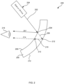
- FIG. 2 is a schematic diagram of the visor 200.
- the visor 200 is a curved element which is supported on the helmet (not shown).
- the visor comprises a polycarbonate visor and includes an inner coating 206 and outer coating 214.
- the visor 2000 provides images to a user 218 represented as an eye and provides an image of the real world 216 and images from a display optic 204 of the imaging system.
- the display optics produces an incident beam 202 is reflected 204 by an inner coating 206 towards the user making the intended primary image 207 ,and is also transmitted 208 through the visor 200.
- the transmitted beam 208 is then reflected 210 by an outer coating 212 towards the eye.
- the beam 210 is then transmitted back through the inner coating 206 giving the undesired secondary reflection 114.
- the display optics 204 provide a virtual image such as symbology which is generated from one or more sensors in the real world 216 or associated with the situation in which the visor is in use.
- symbology is used to describe all types of augmented or virtual imagery which is associated with the needs of a user wearing the visor.
- the sensors may include sensors for: visible and non-visible wavelengths; temperature; location; position; velocity; acceleration and any other sensor appropriate to the situation.
- the inner coating 206 has a reflectivity R D and a transmission coefficient T D .
- the outer coating 212 has a reflectivity R AR .
- the polycarbonate visor 200 has a transmission coefficient of T poly .
- the strength of the primary image 207 is proportional to R D ( ⁇ R D ).
- Figure 3 shows a schematic view of an anti-reflective coating 300 having three notches 302, 304, and 306 centred on respective RGB wavelengths.
- the coating is applied to an optical surface (not shown) of a visor or any other appropriate optical surface.
- the reflectivity of the notches is dependent on a number of variables including notch bandwidth; reflectivity of notches and reflectivity between notches.
- the notches have further variables such as size, depth, spacing, etc.
- the figure shows three notches in three specific locations. It will be appreciated that there may be a different number of notches being located at different specific locations.
- Typical values according to the present invention includes the following possible variables:
- the visor In use the visor enables the presentation to the user of a combination of an augmented or virtual reality image which include real world images and virtual images.
- the virtual images include symbology as described above and the real world includes images of an external scene and/or details of the user location, for example a cockpit.
- the visor is one element that can be coated as described.
- the coatings could be applied to other optical devices including a head mounted or worn device (HMD, HWD), a heads up device (HUD) or any other imaging system where the problem of undesirable secondary reflections occur.
- HMD head mounted or worn device
- HUD heads up device
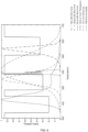
- Figure 4 shows the optical spectrum and filtered spectrum of RGB when impinging on the coating of the present invention. From this and the performance attributes above it is clear to see that the coatings applied to the visor have minimal secondary reflections and that artefacts relating to this will not be viewed by a user. The amount of light entering the visor from the outside world is higher than traditional visors. In addition, the photopic response of the coating ensures a strong transmittance and luminosity when compared to traditional visors.
- visor coating can be optimised so as to maintain or improve on the outside world contrast of a classic P53 or P43 phosphor based heads up display viewed through the visor.
- the wavelength of the green LED light source is as shown in figure 4 .
- the majority of its spectral output is below the spectra of the P53 head up display also shown in figure 4 .
- the green notch reflective part of the combiner coating can be designed so as to maximise the transmission of the P53 spectrum whilst still reflecting the majority of the green LED spectrum.
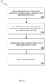
- the process 500 is implemented as described with reference to figure 5 .
- a hard coated polycarbonate visor is taken and a protective dip-hard coating is applied to both inner and outer faces. This helps protect the visor from scratches and helps provide a better base for the dielectric coatings added on top.
- a high performance single or multilayer dielectric anti-reflective layer is applied to the outer face of the visor 504. The layers are designed and made using any appropriate process.
- the anti-reflective coating may be a single layer or a higher performance multilayer coating.
- a dielectric coating is applied to the outside surface of the visor using an appropriate process forming an anti-reflection coating.
- a second coating is designed which consists of several dielectric material layers to be applied to the inner surface of the visor and includes three different notch filters.
- a first notch is located in the blue wavelength region
- a second notch is located in the green wavelength region
- a third notch is located in the red wavelength region.
- the design takes into account the wavelength of the image source, the range of angles over which the coating needs to perform as well as optimising the overall performance considering reflection efficiency and outside world transmission.
- the second coating can include one or more notches.
- a single notch could be used in situations where a single wavelength is required to be viewed and two notches for two wavelengths. Three notches are shown for RGB but for different wavelengths further notches could be included.
- the first notch includes a full-width-half-max of approximately 50nm, and a peak reflectivity of approximately 80%
- the second notch includes a full-width-half-max of approximately 50nm, and a peak reflectivity of approximately 70%
- the third notch has a full-width-half-max of approximately 50nm, and a peak reflectivity of approximately 65%.
- the values above are by way of example.
- the wavelength of the notch will be dependent on the spectrum of the source and the range of angles of incidence that the coating needs to operate over and the measurement angle, and include a centre of the first notch of approximately 440nm, a centre of the second notch of approximately 520nm, and a centre of the third notch of approximately 630nm, by way of example.
- the visor coating is then complete 508.
- the present invention relates to a visor, but it will be understood that the coating may be applied to different surfaces such as for example an eyepiece assembly with similar secondary image issues, optical devices including a head mounted or worn device (HMD, HWD), a heads up device (HUD) or any other imaging system where the problem of undesirable secondary reflections occur.
- HMD head mounted or worn device
- HUD heads up device
- the wavelength ranges discussed herein are examples.
- Other visors or surfaces could be configured for different wavelength regions, in which case the notches would be centred at different wavelengths, from ultra-violet to infra-red.
- the visor with the coating may be used as part of an imaging system 600 as shown in figure 6.
- the imaging system 600 is able to present a user (the eye 602 of which is shown) with optical information.
- the optical system provides to the user real world and virtual information via visor 202.
- the real world image 604 includes the external scene outside the aircraft and an view of the cockpit based information from sensors S1, S2, S3, S4.
- display optics 204 provide virtual image 606 based on information from sensors S1, S2, S3, S4 or the like associated with the aircraft or surroundings.
- the virtual image comprises symbology which is used the assist the user to pilot the aircraft safely.
- the coating on the visor as described optimises the transmission of symbology as there are less secondary reflection issues.
- the ability to provides different numbers of notches and wavelength ranges will further optimise the transmission of symbology as it can be tuned to different situations.
- the helmet may have different visors for different situations.
Landscapes
- Physics & Mathematics (AREA)
- General Physics & Mathematics (AREA)
- Optics & Photonics (AREA)
- Helmets And Other Head Coverings (AREA)
Abstract
A coating for an optical surface for reducing secondary reflections from narrow wavelength band image sources, the coating comprising multiple notch filters located at different predetermined wavelength regions
Description
- The present invention relates to a coating for optical surfaces, preferably but not exclusively for a helmet visor or the like.
- There are many situations in which a user may wear a helmet. For example, a pilot of a plane, a motorbike rider and many other places which may present a hazard to the user. An integral part of the helmet is a visor which provides a view on the surroundings. In some cases, the visor may further provide an augmented or virtual component which allows the user to see other types of information or data.
- A problem which exists with visors is that it is notoriously difficult to deposit a good anti-reflective coating on the outside of a visor as might be used in a visor projected display. The visor is typically made from a polycarbonate which is usually hard coated to reduce scratching. The hard coating tends to optically interfere with the performance of any anti-reflection coating deposited on the hard coating, making the anti-reflection coating inefficient and often limiting its performance to no better than 1%. The resultant optical effect is the introduction of secondary reflections from the outside of the visor which can be objectionable and potentially dangerous in visually critical contexts.
- in a known visor an incident beam passes from display optics towards the visor. The incident beam is reflected by an inner coating towards the user making an intended primary image. The incident beam is also transmitted through the visor and then reflected by an outer coating of the visor towards the eye. The beam is then transmitted back through the inner coating giving secondary reflection . The nature of the secondary reflection is dependent on many variables but is undesirable.
- As a result, there is a need for an improved anti-reflective coating which overcomes at least some of the problems of current visors.
- A further object is to implement a visor having a coating in which the secondaries are mitigated or removed.
- According to an aspect of the present invention, there is provided a coating for an optical surface for reducing secondary reflections from narrow wavelength band image sources, the coating comprising multiple notch filters located at different predetermined wavelength regions.
- In an aspect the multiple notch filters comprise three notch filters.
- In an aspect the different predetermined wavelength regions comprise red, green and blue wavelength regions.
- In an aspect a first notch includes a full-width-half-max of about 50nm, and a peak reflectivity of about 80%.
- In an aspect a second notch includes a full-width-half-max of about 50nm, and a peak reflectivity of about 70%.
- In an aspect a third notch has a full-width-half-max of about 50nm, and a peak reflectivity of about 65%.
- In an aspect a centre of a first notch is approximately 440nm.
- In an aspect a centre of a second notch is approximately 520nm.
- In an aspect a centre of a third notch is approximately 630nm.
- In an aspect the coating further comprises a first dielectric coating under the multiple notch filters.
- In an aspect the coating further comprises a second dielectric coating over the multiple notch filters.
- In an aspect the second dielectric coating comprises a dip-hard coating,
- According to an aspect of the present invention, there is provided a visor having a coating according to another aspect.
- In an aspect the visor is made from a polycarbonate material
- In an aspect the coating is located on an inner surface of the visor.
- In an aspect a further anti-reflective coating is located on an outer surface of the visor.
- According to an aspect of the present invention, there is provided a helmet including a visor according to another aspect
- According to an aspect of the present invention, there is provided a method of applying a coating, that reduces secondary reflection from narrow wavelength band images sources to an optical surface, the method comprises applying multiple layers of material each having a notch filter located at different predetermined wavelength regions.
- In an aspect the method comprises applying three layers of material to form respective notches.
- In an aspect further comprising applying the multiple layers in the red, green and blue wavelength regions .
- In an aspect further comprising forming a first notch includes a full-width-half-max of about 50nm, and a peak reflectivity of about 80%.
- In an aspect further comprising forming a second notch includes a full-width-half-max of about 50nm, and a peak reflectivity of about 70%.
- In an aspect further comprising forming a third notch has a full-width-half-max of about 50nm, and a peak reflectivity of about 65%.
- In an aspect further comprising forming a centre of a first notch at approximately 440nm; a centre of a second notch at approximately 520nm and a centre of a third notch at approximately 630nm.
- According to an aspect of the present invention, there is provided a method of forming a visor comprising applying a coating made by the method according to another aspect to a polycarbonate visor.
- Embodiments of the invention will now be described by way of example only with reference to the figures, in which:
-
Figure 1 shows a simplified diagram of a helmet including a visor according to the present invention; -
Figure 2 is a simplified view of the visor offigure 1 ; -
Figure 3 is a representation of a spectral profile of a coating for a visor according to the present invention; -
Figure 4 is a graph representing the optical properties achieved using the visor of the present invention. -
Figure 5 is a flow diagram showing how an anti-reflective coating is produced; - The present invention relates to a visor having an anti-reflective coating which both reduces secondary reflections and further augments the brightness of the image produced by the visor.
- The secondary reflections are reduced by making the reflection of the image from the inside of the visor stronger. This gives rise to a visor in which the main image is brighter and less light hits the outer surface so less is reflected back. An issue with this is that if the inside surface has a spectrally broad reflective coating, then in making this more reflective there will be a reduction of light from the outside world transmission. The present invention is to use spectrally narrow band image sources for each of red, green and blue (RGB) wavelengths and to provide a narrow notch filter in the reflection coating on the visor so as to efficiently reflect the RGB image and wide enough to maintain an optimal outside world transmission.
-
Figure 1 illustrates ahelmet 200 including avisor 202. The helmet is suitable for being worn on the head of a user (not shown). In use, the user wears the helmet for head protection and uses the visor to see a real image of the outside world and augmented or virtual images from an imaging system (not shown). The imaging system is able to combine the real world images and the augmented or virtual images. - A typical user is a pilot of a vehicle such as an aircraft or any user who needs head protection using an imaging system.
-
Figure 2 is a schematic diagram of thevisor 200. Thevisor 200 is a curved element which is supported on the helmet (not shown). The visor comprises a polycarbonate visor and includes aninner coating 206 andouter coating 214. The visor 2000 provides images to auser 218 represented as an eye and provides an image of the real world 216 and images from adisplay optic 204 of the imaging system. - The display optics produces an
incident beam 202 is reflected 204 by aninner coating 206 towards the user making the intendedprimary image 207 ,and is also transmitted 208 through thevisor 200. The transmittedbeam 208 is then reflected 210 by anouter coating 212 towards the eye. Thebeam 210 is then transmitted back through theinner coating 206 giving the undesired secondary reflection 114. - The
display optics 204 provide a virtual image such as symbology which is generated from one or more sensors in the real world 216 or associated with the situation in which the visor is in use. The term symbology is used to describe all types of augmented or virtual imagery which is associated with the needs of a user wearing the visor. The sensors may include sensors for: visible and non-visible wavelengths; temperature; location; position; velocity; acceleration and any other sensor appropriate to the situation. - The
inner coating 206 has a reflectivity RD and a transmission coefficient TD. Theouter coating 212 has a reflectivity RAR. Thepolycarbonate visor 200 has a transmission coefficient of Tpoly. The strength of theprimary image 207 is proportional to RD (∝RD). The strength of thesecondary reflection 214 is proportional to TD 2 and proportional to Tpoly 2 and RAR (∝TD 2. Tpoly 2. RAR). Look at the strength of thesecondary reflection 214 relative to the primary then:
- By maximising transmissivity of light from the real world Tpoly ~1 the relative strength of the secondary reflection becomes:

- Assuming that the
inner coating 206 is of reasonable quality, then for any wavelength in the visible (TD+RD)~1 increasing the reflectivity of the inner coating for the source wavelengths will also reduce the transmission coefficient of the inner coating. - An understanding of these observations has led to the following solution to reduce secondary reflections and maximise transmissivity of light from the real world in visors.
-
Figure 3 shows a schematic view of ananti-reflective coating 300 having threenotches - By reflecting the RGB off the
inside surface 306, the amount of light reaching the outer surface 308 is reduced which reduces the amount of light reflected by the anti-reflection coating on outer surface 308 so reducing the strength of this reflection compared to the primary image off the inside surface. Typical values according to the present invention includes the following possible variables: - Reflectivity of notch for each of RGB
- ∘ 65% (Red)
- ∘ 70% (Green)
- ∘ 80% (Blue)
- Reflectivity between notches
∘ 5% - Relative Luminance
- ∘ 193% baseline (Red)
- ∘ 175% baseline (Green)
- ∘ 183% baseline (Blue)
- Coating effective index
∘ n* = 2.0 - This set of variable used as one example gives the following performance attributes.
- Secondary Reflection (0.5% AR)
- 0.153% (Red), 0.215% (Green), 0.186% (Blue)
- Outside World Transmission 66%
- P53 Transmission 93%
- Outside World Colouration < 0.042 units in CIE 1976 colour space (u', V).
- In use the visor enables the presentation to the user of a combination of an augmented or virtual reality image which include real world images and virtual images. The virtual images include symbology as described above and the real world includes images of an external scene and/or details of the user location, for example a cockpit.
- It should be noted that the visor is one element that can be coated as described. The coatings could be applied to other optical devices including a head mounted or worn device (HMD, HWD), a heads up device (HUD) or any other imaging system where the problem of undesirable secondary reflections occur.
-
Figure 4 shows the optical spectrum and filtered spectrum of RGB when impinging on the coating of the present invention. From this and the performance attributes above it is clear to see that the coatings applied to the visor have minimal secondary reflections and that artefacts relating to this will not be viewed by a user. The amount of light entering the visor from the outside world is higher than traditional visors. In addition, the photopic response of the coating ensures a strong transmittance and luminosity when compared to traditional visors. - It will be appreciated that the specific variables and results may not be exactly as indicated but can include many alternatives.
- An additional advantage of the visor coating is that the design can be optimised so as to maintain or improve on the outside world contrast of a classic P53 or P43 phosphor based heads up display viewed through the visor. Generally the wavelength of the green LED light source is as shown in
figure 4 . The majority of its spectral output is below the spectra of the P53 head up display also shown infigure 4 . The green notch reflective part of the combiner coating can be designed so as to maximise the transmission of the P53 spectrum whilst still reflecting the majority of the green LED spectrum. If the typical values for the transmission of P53 spectrum through the visor coating given above (93%) compared to the outside world transmission also given above (66%) then as 93%>66% the P53 HUD symbology contrast against the outside world has been improved when looking through the visor. To further improve this technique, the now unused upper wavelength part of the green LED spectra would ideally be filtered out in the HMD display optics prior to it ever reaching the visor so as to prevent it from contributing to the secondary image. - In order to apply the anti-reflective coating of the present invention the
process 500 is implemented as described with reference tofigure 5 . - In a first step 502 a hard coated polycarbonate visor is taken and a protective dip-hard coating is applied to both inner and outer faces. This helps protect the visor from scratches and helps provide a better base for the dielectric coatings added on top. A high performance single or multilayer dielectric anti-reflective layer is applied to the outer face of the
visor 504. The layers are designed and made using any appropriate process. The anti-reflective coating may be a single layer or a higher performance multilayer coating. - In a second step 504 a dielectric coating is applied to the outside surface of the visor using an appropriate process forming an anti-reflection coating.
- In a third step 506 a second coating is designed which consists of several dielectric material layers to be applied to the inner surface of the visor and includes three different notch filters. For an RGB display a first notch is located in the blue wavelength region, a second notch is located in the green wavelength region and a third notch is located in the red wavelength region. The design takes into account the wavelength of the image source, the range of angles over which the coating needs to perform as well as optimising the overall performance considering reflection efficiency and outside world transmission.
- It should be noted that the second coating can include one or more notches. A single notch could be used in situations where a single wavelength is required to be viewed and two notches for two wavelengths. Three notches are shown for RGB but for different wavelengths further notches could be included.
- The first notch includes a full-width-half-max of approximately 50nm, and a peak reflectivity of approximately 80%, the second notch includes a full-width-half-max of approximately 50nm, and a peak reflectivity of approximately 70%, and the third notch has a full-width-half-max of approximately 50nm, and a peak reflectivity of approximately 65%. The values above are by way of example. The wavelength of the notch will be dependent on the spectrum of the source and the range of angles of incidence that the coating needs to operate over and the measurement angle, and include a centre of the first notch of approximately 440nm, a centre of the second notch of approximately 520nm, and a centre of the third notch of approximately 630nm, by way of example.
- The visor coating is then complete 508.
- The present invention relates to a visor, but it will be understood that the coating may be applied to different surfaces such as for example an eyepiece assembly with similar secondary image issues, optical devices including a head mounted or worn device (HMD, HWD), a heads up device (HUD) or any other imaging system where the problem of undesirable secondary reflections occur. The wavelength ranges discussed herein are examples. Other visors or surfaces could be configured for different wavelength regions, in which case the notches would be centred at different wavelengths, from ultra-violet to infra-red.
- In use the visor with the coating may be used as part of an
imaging system 600 as shown in figure 6. Theimaging system 600 is able to present a user (the eye 602 of which is shown) with optical information. Take the example of an aircraft and a pilot, the optical system provides to the user real world and virtual information viavisor 202. The real world image 604 includes the external scene outside the aircraft and an view of the cockpit based information from sensors S1, S2, S3, S4. In addition,display optics 204 provide virtual image 606 based on information from sensors S1, S2, S3, S4 or the like associated with the aircraft or surroundings. The virtual image comprises symbology which is used the assist the user to pilot the aircraft safely. The coating on the visor as described optimises the transmission of symbology as there are less secondary reflection issues. - It should further be noted that the ability to provides different numbers of notches and wavelength ranges will further optimise the transmission of symbology as it can be tuned to different situations. The helmet may have different visors for different situations.
- Although the present invention has been described in connection with some aspects, it is not intended to be limited to the specific form set forth herein. Rather, the scope of the present invention is limited only by the accompanying claims. Additionally, although a feature may appear to be described in connection with particular aspects, one skilled in the art would recognize that various features of the described aspects may be combined in accordance with the invention. In the claims, the term 'comprising' does not exclude the presence of other elements or steps.
- Furthermore, although individually listed, a plurality of means, elements or method steps may be implemented by, for example, a single unit or step. Additionally, although individual features may be included in different claims, these may possibly be advantageously combined, and the inclusion in different claims does not imply that a combination of features is not feasible and/or advantageous. Also, the inclusion of a feature in one category of claims does not imply a limitation to this category, but rather indicates that the feature is equally applicable to other claim categories, as appropriate.
Claims (15)
- A coating (400) for an optical surface for reducing secondary reflections from narrow wavelength band image sources, the coating comprising multiple notch filters (402, 404, 406) located at different predetermined wavelength regions.
- The coating according to claim 1, wherein the multiple notch filters comprise three notch filters.
- The coating according to claim 1 or claim 2, wherein the different predetermined wavelength regions comprise red, green and blue wavelength regions.
- The coating according to any one of the preceding claims, wherein a first notch includes a full-width-half-max of about 50nm, and a peak reflectivity of about 80%.
- The coating according to any one of the preceding claims, wherein a second notch includes a full-width-half-max of about 50nm, and a peak reflectivity of about 70%.
- The coating according to any one of the preceding claims, wherein a third notch has a full-width-half-max of about 50nm, and a peak reflectivity of about 65%.
- The coating according to any one of the preceding claims, wherein a centre of a first notch is approximately 440nm; a centre of a second notch is approximately 520nm and a centre of a third notch is approximately 630nm.
- The coating according to any one of the preceding claims, wherein the coating further comprises a first dielectric coating under the multiple notch filters and a second dielectric coating over the multiple notch filters.
- A visor (202) having a coating (400) according to any preceding claim.
- The visor according to claims 9, wherein the visor is made from a polycarbonate material
- The visor according to claim 9 or claim 10, wherein the coating is located on an inner surface of the visor.
- A helmet (200) including a visor (202) according to any one of claims 9 to 11.
- A method (600) of applying a coating, that reduces secondary reflection from narrow wavelength band images sources to an optical surface, the method comprises applying multiple layers of material (604) each having a notch filter (402, 404, 406) located at different predetermined wavelength regions.
- The method according to claim 13, wherein the method comprises applying three layers of material to form respective notches in the red, green and blue wavelength regions .
- A method (600) of forming a visor (202) comprising applying a coating (400) made by the method according to any one of claims 13 to 14 to a polycarbonate visor.
Priority Applications (6)
| Application Number | Priority Date | Filing Date | Title |
|---|---|---|---|
| EP22275103.4A EP4312072A1 (en) | 2022-07-27 | 2022-07-27 | A coating for optical surfaces |
| EP23750708.2A EP4562464A1 (en) | 2022-07-27 | 2023-07-25 | A coating for optical surfaces |
| US18/998,341 US20250383487A1 (en) | 2022-07-27 | 2023-07-25 | Coating for optical surfaces |
| GB2311398.8A GB2622684A (en) | 2022-07-27 | 2023-07-25 | A coating for optical surfaces |
| PCT/GB2023/051956 WO2024023502A1 (en) | 2022-07-27 | 2023-07-25 | A coating for optical surfaces |
| TW112128153A TW202419899A (en) | 2022-07-27 | 2023-07-27 | A coating for optical surfaces |
Applications Claiming Priority (1)
| Application Number | Priority Date | Filing Date | Title |
|---|---|---|---|
| EP22275103.4A EP4312072A1 (en) | 2022-07-27 | 2022-07-27 | A coating for optical surfaces |
Publications (1)
| Publication Number | Publication Date |
|---|---|
| EP4312072A1 true EP4312072A1 (en) | 2024-01-31 |
Family
ID=82780953
Family Applications (1)
| Application Number | Title | Priority Date | Filing Date |
|---|---|---|---|
| EP22275103.4A Ceased EP4312072A1 (en) | 2022-07-27 | 2022-07-27 | A coating for optical surfaces |
Country Status (1)
| Country | Link |
|---|---|
| EP (1) | EP4312072A1 (en) |
Citations (3)
| Publication number | Priority date | Publication date | Assignee | Title |
|---|---|---|---|---|
| US20160377868A1 (en) * | 2014-03-18 | 2016-12-29 | 3M Innovative Properties Company | Low profile image combiner for near-eye displays |
| US20170329139A1 (en) * | 2016-02-26 | 2017-11-16 | Fusar Technologies, Inc. | Method and notch reflector projection system |
| GB2579370A (en) * | 2018-11-29 | 2020-06-24 | Bae Systems Plc | Display device |
-
2022
- 2022-07-27 EP EP22275103.4A patent/EP4312072A1/en not_active Ceased
Patent Citations (3)
| Publication number | Priority date | Publication date | Assignee | Title |
|---|---|---|---|---|
| US20160377868A1 (en) * | 2014-03-18 | 2016-12-29 | 3M Innovative Properties Company | Low profile image combiner for near-eye displays |
| US20170329139A1 (en) * | 2016-02-26 | 2017-11-16 | Fusar Technologies, Inc. | Method and notch reflector projection system |
| GB2579370A (en) * | 2018-11-29 | 2020-06-24 | Bae Systems Plc | Display device |
Similar Documents
| Publication | Publication Date | Title |
|---|---|---|
| EP2349151B1 (en) | Split laser eye protection system | |
| EP3032978B1 (en) | Improvements in and relating to visors | |
| CA2865223C (en) | System and method for projecting synthetic imagery and scenic imagery using an optical component comprising a diffractive optical element pattern | |
| US9946068B2 (en) | Optical waveguide and display device | |
| US20250076660A1 (en) | Optical structure for augmented reality display | |
| US5949583A (en) | Head-mounted display with image generator, fold mirror and mirror for transmission to the eye position of the user | |
| EP0479439B1 (en) | Optical display apparatus | |
| WO2017131983A1 (en) | Mixed environment display device and waveguide cross-coupling suppressors | |
| GB2579370A (en) | Display device | |
| US8441734B2 (en) | Head-up display with optical combination providing protection against solar illumination | |
| US7164535B2 (en) | Optical coating and configuration for tailored spectral characteristics over viewing angle | |
| US20150029410A1 (en) | Head up display lens | |
| WO1996001439A1 (en) | Display system intended to be attached to the head or to a helmet, and a helmet provided with such a display system | |
| WO2023137123A1 (en) | Image light guide with interference filter | |
| US20250383487A1 (en) | Coating for optical surfaces | |
| EP3667396A1 (en) | Display device | |
| EP2837299A1 (en) | Improvements in and relating to visors | |
| CN113272711B (en) | Light guide arrangement, imaging optical unit, head mounted display and method for improving imaging quality of imaging optical unit | |
| JP7830160B2 (en) | Image display device | |
| EP4575609A1 (en) | Light security for head mounted displays | |
| CN112630971A (en) | Augmented reality display device | |
| WO1997009652A1 (en) | Display system intended to be attached to the head or to a helmet, and a helmet provided with such a display system | |
| GB2519404A (en) | Improvements in and relating to visors |
Legal Events
| Date | Code | Title | Description |
|---|---|---|---|
| PUAI | Public reference made under article 153(3) epc to a published international application that has entered the european phase |
Free format text: ORIGINAL CODE: 0009012 |
|
| STAA | Information on the status of an ep patent application or granted ep patent |
Free format text: STATUS: THE APPLICATION HAS BEEN PUBLISHED |
|
| AK | Designated contracting states |
Kind code of ref document: A1 Designated state(s): AL AT BE BG CH CY CZ DE DK EE ES FI FR GB GR HR HU IE IS IT LI LT LU LV MC MK MT NL NO PL PT RO RS SE SI SK SM TR |
|
| STAA | Information on the status of an ep patent application or granted ep patent |
Free format text: STATUS: THE APPLICATION HAS BEEN REFUSED |
|
| 18R | Application refused |
Effective date: 20240219 |