EP4312053A1 - Online magnitude calibration of radar sensor based on radar map of known objects - Google Patents
Online magnitude calibration of radar sensor based on radar map of known objects Download PDFInfo
- Publication number
- EP4312053A1 EP4312053A1 EP22187754.1A EP22187754A EP4312053A1 EP 4312053 A1 EP4312053 A1 EP 4312053A1 EP 22187754 A EP22187754 A EP 22187754A EP 4312053 A1 EP4312053 A1 EP 4312053A1
- Authority
- EP
- European Patent Office
- Prior art keywords
- radar
- radar sensor
- objects
- known static
- sensor
- Prior art date
- Legal status (The legal status is an assumption and is not a legal conclusion. Google has not performed a legal analysis and makes no representation as to the accuracy of the status listed.)
- Pending
Links
Images



Classifications
-
- G—PHYSICS
- G01—MEASURING; TESTING
- G01S—RADIO DIRECTION-FINDING; RADIO NAVIGATION; DETERMINING DISTANCE OR VELOCITY BY USE OF RADIO WAVES; LOCATING OR PRESENCE-DETECTING BY USE OF THE REFLECTION OR RERADIATION OF RADIO WAVES; ANALOGOUS ARRANGEMENTS USING OTHER WAVES
- G01S7/00—Details of systems according to groups G01S13/00, G01S15/00, G01S17/00
- G01S7/02—Details of systems according to groups G01S13/00, G01S15/00, G01S17/00 of systems according to group G01S13/00
- G01S7/40—Means for monitoring or calibrating
- G01S7/4004—Means for monitoring or calibrating of parts of a radar system
- G01S7/4008—Means for monitoring or calibrating of parts of a radar system of transmitters
- G01S7/4013—Means for monitoring or calibrating of parts of a radar system of transmitters involving adjustment of the transmitted power
-
- G—PHYSICS
- G01—MEASURING; TESTING
- G01S—RADIO DIRECTION-FINDING; RADIO NAVIGATION; DETERMINING DISTANCE OR VELOCITY BY USE OF RADIO WAVES; LOCATING OR PRESENCE-DETECTING BY USE OF THE REFLECTION OR RERADIATION OF RADIO WAVES; ANALOGOUS ARRANGEMENTS USING OTHER WAVES
- G01S7/00—Details of systems according to groups G01S13/00, G01S15/00, G01S17/00
- G01S7/02—Details of systems according to groups G01S13/00, G01S15/00, G01S17/00 of systems according to group G01S13/00
- G01S7/40—Means for monitoring or calibrating
- G01S7/4052—Means for monitoring or calibrating by simulation of echoes
- G01S7/4082—Means for monitoring or calibrating by simulation of echoes using externally generated reference signals, e.g. via remote reflector or transponder
- G01S7/4091—Means for monitoring or calibrating by simulation of echoes using externally generated reference signals, e.g. via remote reflector or transponder during normal radar operation
-
- G—PHYSICS
- G01—MEASURING; TESTING
- G01S—RADIO DIRECTION-FINDING; RADIO NAVIGATION; DETERMINING DISTANCE OR VELOCITY BY USE OF RADIO WAVES; LOCATING OR PRESENCE-DETECTING BY USE OF THE REFLECTION OR RERADIATION OF RADIO WAVES; ANALOGOUS ARRANGEMENTS USING OTHER WAVES
- G01S13/00—Systems using the reflection or reradiation of radio waves, e.g. radar systems; Analogous systems using reflection or reradiation of waves whose nature or wavelength is irrelevant or unspecified
- G01S13/88—Radar or analogous systems specially adapted for specific applications
- G01S13/93—Radar or analogous systems specially adapted for specific applications for anti-collision purposes
- G01S13/931—Radar or analogous systems specially adapted for specific applications for anti-collision purposes of land vehicles
-
- G—PHYSICS
- G01—MEASURING; TESTING
- G01S—RADIO DIRECTION-FINDING; RADIO NAVIGATION; DETERMINING DISTANCE OR VELOCITY BY USE OF RADIO WAVES; LOCATING OR PRESENCE-DETECTING BY USE OF THE REFLECTION OR RERADIATION OF RADIO WAVES; ANALOGOUS ARRANGEMENTS USING OTHER WAVES
- G01S7/00—Details of systems according to groups G01S13/00, G01S15/00, G01S17/00
- G01S7/02—Details of systems according to groups G01S13/00, G01S15/00, G01S17/00 of systems according to group G01S13/00
- G01S7/40—Means for monitoring or calibrating
-
- G—PHYSICS
- G01—MEASURING; TESTING
- G01S—RADIO DIRECTION-FINDING; RADIO NAVIGATION; DETERMINING DISTANCE OR VELOCITY BY USE OF RADIO WAVES; LOCATING OR PRESENCE-DETECTING BY USE OF THE REFLECTION OR RERADIATION OF RADIO WAVES; ANALOGOUS ARRANGEMENTS USING OTHER WAVES
- G01S7/00—Details of systems according to groups G01S13/00, G01S15/00, G01S17/00
- G01S7/02—Details of systems according to groups G01S13/00, G01S15/00, G01S17/00 of systems according to group G01S13/00
- G01S7/41—Details of systems according to groups G01S13/00, G01S15/00, G01S17/00 of systems according to group G01S13/00 using analysis of echo signal for target characterisation; Target signature; Target cross-section
- G01S7/411—Identification of targets based on measurements of radar reflectivity
-
- G—PHYSICS
- G01—MEASURING; TESTING
- G01S—RADIO DIRECTION-FINDING; RADIO NAVIGATION; DETERMINING DISTANCE OR VELOCITY BY USE OF RADIO WAVES; LOCATING OR PRESENCE-DETECTING BY USE OF THE REFLECTION OR RERADIATION OF RADIO WAVES; ANALOGOUS ARRANGEMENTS USING OTHER WAVES
- G01S7/00—Details of systems according to groups G01S13/00, G01S15/00, G01S17/00
- G01S7/02—Details of systems according to groups G01S13/00, G01S15/00, G01S17/00 of systems according to group G01S13/00
- G01S7/41—Details of systems according to groups G01S13/00, G01S15/00, G01S17/00 of systems according to group G01S13/00 using analysis of echo signal for target characterisation; Target signature; Target cross-section
- G01S7/411—Identification of targets based on measurements of radar reflectivity
- G01S7/412—Identification of targets based on measurements of radar reflectivity based on a comparison between measured values and known or stored values
-
- G—PHYSICS
- G01—MEASURING; TESTING
- G01S—RADIO DIRECTION-FINDING; RADIO NAVIGATION; DETERMINING DISTANCE OR VELOCITY BY USE OF RADIO WAVES; LOCATING OR PRESENCE-DETECTING BY USE OF THE REFLECTION OR RERADIATION OF RADIO WAVES; ANALOGOUS ARRANGEMENTS USING OTHER WAVES
- G01S13/00—Systems using the reflection or reradiation of radio waves, e.g. radar systems; Analogous systems using reflection or reradiation of waves whose nature or wavelength is irrelevant or unspecified
- G01S13/86—Combinations of radar systems with non-radar systems, e.g. sonar, direction finder
Definitions
- An autonomous vehicle is a motorized vehicle that can navigate without a human driver.
- An exemplary autonomous vehicle includes a plurality of sensor systems, such as, but not limited to, a camera sensor system, a light detection and ranging (LIDAR) sensor system, or a radio detection and ranging (RADAR) sensor system, amongst others.
- the autonomous vehicle operates (i.e., steering, braking, propulsion, etc.) based upon sensor signals from the sensor systems.
- Some vehicles use multiple sensors of the same given type, such as multiple radar sensors, so that the vehicle has a larger field of view than a single such sensor would ordinarily provide. Since the autonomous vehicle depends on the sensor systems to provide information of the surrounding environment to operate safely without a human driver, it is imperative that the sensor systems provide accurate information. For a variety of reasons, such as, but not limited to, differences between sensors, obstructed views of the environment around the vehicle, manufacturing defects or other discrepancies in sensors, in vehicles, and/or in mounting hardware, and prolonged exposure to the environment, sensor measurements may not be an accurate representative of an environment nearby the vehicle.
- sensor systems such as radar sensor systems, should be calibrated often.
- An exemplary implementation of a method of calibrating a radar sensor includes transmitting a radar signal into an operating environment and receiving radar returns from a plurality of objects in the operating environment based on the radar signal sent. Each of the radar returns has a magnitude associated with each of the plurality of objects. At least a subset of the objects are known static objects (e.g., stop signs, bridges, buildings, etc.). The method further includes identifying a location and orientation of the radar sensor when the signal was sent and identifying expected reflectance values for each of the plurality of known static objects.
- identifying expected reflectance values for each of the plurality of known static objects includes accessing a predetermined radar map of the operating environment of the radar sensor containing the plurality of known static objects.
- the predetermined radar map identifies expected reflectance values for each of the known static objects.
- a radar sensor coupled to an autonomous vehicle is located in an operating environment.
- the radar sensor can include a signal processing component configured to capture a plurality of radar returns from the one or more objects in the environment. At least a subset of the objects are known static objects.
- the system further includes a radar map module configured to access a predetermined radar map of the radar data for the known static objects in the operating environment, a radar sensor position module configured to identify a location and orientation of the radar sensor when the signal was sent, and a comparison module configured to identify expected reflectance values for each of the known static objects based on the identified location and orientation of the radar sensor.
- the system also includes a correction module configured to calculate a conversion function to adjust the magnitudes of each of the radar returns from the known static objects to an estimated reflectance value based on the expected reflectance values for each of the known static objects and to adjust an output of the radar sensor based on the conversion function.
- a correction module configured to calculate a conversion function to adjust the magnitudes of each of the radar returns from the known static objects to an estimated reflectance value based on the expected reflectance values for each of the known static objects and to adjust an output of the radar sensor based on the conversion function.
- the term "or” is intended to mean an inclusive “or” rather than an exclusive “or.” That is, unless specified otherwise, or clear from the context, the phrase “X employs A or B” is intended to mean any of the natural inclusive permutations. That is, the phrase “X employs A or B” is satisfied by any of the following instances: X employs A; X employs B; or X employs both A and B.
- the articles “a” and “an” as used in this application and the appended claims should generally be construed to mean “one or more” unless specified otherwise or clear from the context to be directed to a singular form.
- the terms “component”, “system”, and “module” are intended to encompass computer-readable data storage that is configured with computer-executable instructions that cause certain functionality to be performed when executed by a processor.
- the computer-executable instructions may include a routine, a function, or the like. It is also to be understood that a component or system may be localized on a single device or distributed across several devices.
- the term “exemplary” is intended to mean serving as an illustration or example of something and is not intended to indicate a preference.
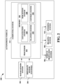
- Fig. 1 is a high-level illustration of an exemplary radar sensor 100.
- the radar sensor 100 may be any suitable radar sensor 100.
- the radar sensor 100 includes a transmit antenna 102, a receive antenna 104, and a radar computing component 106.
- the radar computing component 106 is configured to prepare radar signals that are transmitted by the transmit antenna 102, and to compute object solutions indicating estimated positions and/or velocities of objects based upon radar returns received by the receive antenna 104.
- various components of the radar sensor 100 can be integrated as a same system-on-a-chip (SoC).
- the radar sensor 100 can be employed on a vehicle, such as a land vehicle, an aircraft, to identify positions and velocities of objects in the operational environment of the vehicle.
- SoC system-on-a-chip
- the radar computing component 106 comprises a signal generator component 108 that prepares radar signals for transmission by way of the transmit antenna 102 and a radar analysis component 110 that analyzes the radar data received by the receive antenna 104.
- the radar sensor 100 is configured to repeatedly, or continuously, transmit radar signals (e.g., pulse sequences) by way of the transmit antenna 102, and to receive radar returns repeatedly, or continuously, by way of the receive antenna 104.
- the radar returns received by the receive antenna 104 comprise reflections, from objects in the operational environment of the radar sensor 100, of radar signals emitted by the transmit antenna 102. Responsive to receipt of radar returns from the operational environment of the radar sensor 100, the receive antenna 104 outputs an electrical signal that is indicative of the received radar returns. This electrical signal is referred to herein as a radar signal and is transmitted along one or more transmission lines in the radar sensor 100, as distinct from radar returns that are received by the receive antenna 104 as radiated signals propagating through air or free space in the operational environment of the radar sensor 100.
- the radar sensor 100 further includes a signal processing component 112.
- the signal processing component 112 receives a radar signal from the receive antenna 104.
- the signal processing component 112 for instance, can capture a plurality of radar returns from a plurality of objects in an operating environment.
- the signal processing component 112 is configured to perform various analog signal processing operations over radar signals received from the receive antenna 104.
- the signal processing component 112 can perform various mixing, filtering, and amplification operations on radar signals output by the receive antenna 104.
- the signal processing component 112 can be configured to perform a variety of these signal processing operations (e.g., mixing) based further upon a radar signal transmitted by the transmit antenna 102.
- the radar computing component 106 receives the radar data via the signal processing component 112.
- the radar analysis component 110 of the radar computing component 106 is configured to determine properties of the each of the objects in the operational environment of the radar sensor 100 based upon the radar data.
- the radar analysis component 110 can compute a range, a bearing, and/or a velocity of an object in the operational environment of the radar sensor 100 based upon the radar data.
- the radar sensor 100 also includes a sensor output 114 indicative of the analyzed radar data.
- AV 200 an exemplary AV 200 is illustrated, wherein the AV 200 can navigate about roadways without human conduction based upon sensor signals output by sensor systems of the AV 200.
- the AV 200 includes a plurality of sensor systems 202-204.
- the sensor systems 202-204 may be of different types.
- the sensor systems 202-204 include a radar sensor system 202 and disparate sensor system(s) 204 (e.g., substantially any number and types of sensor systems in addition to the radar sensor system 202).
- the radar sensor system 202 can be or include the radar sensor 100 (or a plurality of radar sensors each similar to the radar sensor 100).
- the disparate sensor system(s) 204 can include a lidar sensor system, a camera (image) system, and/or a sonar system.
- Other exemplary sensor systems that can additionally or alternatively be included in the disparate sensor system(s) 204 include GPS sensor systems, inertial sensor systems, infrared sensor systems, and the like.
- the various sensor systems 202-204 are arranged about the AV 200.
- the sensor systems 202-204 are configured to repeatedly (e.g., continuously, or periodically) output sensor data that is representative of objects and conditions in the driving environment of the AV 200.
- the AV 200 further includes several mechanical systems that are used to effectuate appropriate motion of the AV 200.
- the mechanical systems can include but are not limited to, a vehicle propulsion system 206, a braking system 208, and a steering system 210.
- the vehicle propulsion system 206 may be an electric engine, a combustion engine, or a combination thereof.
- the braking system 208 can include an engine brake, brake pads, actuators, a regenerative braking system, and/or any other suitable componentry that is configured to assist in decelerating the AV 200.
- the steering system 210 includes suitable componentry that is configured to control the direction of movement of the AV 200.
- the AV 200 additionally comprises a computing system 212 that is in communication with the sensor systems 202-204 and is further in communication with the vehicle propulsion system 206, the braking system 208, and the steering system 210.
- the computing system 212 includes a processor 214 and memory 216 that includes computer-executable instructions that are executed by the processor 214.
- the processor 214 can be or include a graphics processing unit (GPU), a plurality of GPUs, a central processing unit (CPU), a plurality of CPUs, an application-specific integrated circuit (ASIC), a microcontroller, a programmable logic controller (PLC), a field programmable gate array (FPGA), or the like.
- the memory 216 comprises a localization system 218, a perception system 220, a planning system 222, and a control system 224.
- the localization system 218 is configured to determine a local position of the AV 200.
- the perception system 220 is configured to identify the presence of objects and/or characteristics of objects in the driving environment of the AV 200 based upon sensor data output by the sensor systems 202-204.
- the planning system 222 is configured to plan a route and/or a maneuver of the AV 200 based upon data pertaining to objects in the driving environment that are output by the perception system 220.
- the control system 224 is configured to control the mechanical systems 206-210 of the AV 200 to effectuate appropriate motion to cause the AV 200 to execute a maneuver planned by the planning system 222.
- the perception system 220 is configured to identify objects in proximity to the AV 200 that are captured in sensor signals output by the sensor systems 202-204.
- the perception system 220 can be configured to identify the presence of an object in the driving environment of the AV 200 based upon images generated by a camera system included in the disparate sensor system(s) 204.
- the perception system 220 can be configured to determine a presence and position of an object based upon radar data output by the radar sensor system 202.
- the radar sensor system 202 can include one or more radar sensors 100.
- the perception system 220 can be configured to identify a position of an object in the driving environment of the AV 200 based upon the estimated range output by the radar sensor 100.
- the AV 200 can be included in a fleet of AVs that are in communication with a common server computing system.
- the server computing system can control the fleet of AVs such that radar sensor systems of AVs operating in a same driving environment (e.g., within line of sight of one another, or within a threshold distance of one another) employ different pulse sequence carrier frequencies.
- a radar sensor system of a first AV can be controlled so as not to transmit pulse sequences having same center frequencies as pulse sequences transmitted by a radar sensor system of a second AV at the same time.
- the radar sensor system of the first AV can be controlled to transmit pulse sequences in a different order than a radar sensor system of a second AV.
- the radar sensor system of the first AV can be configured to transmit a set of pulse sequences at four different center frequencies A, B, C, and D in an order A, B, C, D.
- the radar sensor system of the second AV can be configured to transmit pulse sequences using a same set of center frequencies in a frequency order B, A, D, C.
- the radar sensor 100 is calibrated with the use of a radar map of the environment that the radar sensor 100 is operating in (i.e., the operating environment).
- the radar sensor 100 can include a radar map module 116.
- the radar map module 116 is configured to access a predetermined radar map of radar data for known static objects in the operating environment. Examples of known static objects that can be represented in the predetermined radar map can include signs, buildings, bridges, or substantially any other static object that remains fixed in the environment.
- the radar sensor 100 can include the predetermined radar map, which can be accessed by the radar map module 116.
- the computing system 212 of the autonomous vehicle 200 can store the predetermined radar map (e.g., the radar map can be stored in a data store of the computing system 212); following this example, the radar map module 116 can access the predetermined radar map retained by the computing system 212 of the autonomous vehicle 200.
- the predetermined radar map may only include a select group of known static objects in the operating environment for use in calibrating the radar sensor 100.
- the radar map includes expected radar reflectance values for a plurality of known static objects in the operating environment as a function of range and angle of the radar sensor 100.
- the localized position and orientation of the radar sensor within the map is defined by coordinates X1, Y1, Z1 with three rotation angles (RX, RY, RZ (i.e., yaw, pitch, and roll).
- RX, RY, RZ i.e., yaw, pitch, and roll.
- the radar map will contain an expected reflectance value that a radar sensor at coordinates X1, Y1, Z1, and orientation RX, RY, RZ should receive from the given static object.
- the radar map provides information regarding how the reflectance value is impacted by the range from the object and by the orientation of the radar sensor.
- the radar map may be created, for example, by gathering radar data from radar systems of AVs as those AVs drive around the operating environment (e.g., town, city, etc.). While driving around the operating environment, the radar system of each of the AVs records the position and orientation of the radar sensors of the radar systems of the AVs and records the magnitude of the radar return and location of the object generating the return.
- the operating environment e.g., town, city, etc.
- the radar sensor 100 further includes a radar sensor position module 118 configured to identify a location and orientation of the radar sensor 100.
- the radar sensor position module 118 may utilize any suitable sensing devices for determining the position and the orientation of the radar sensor 100 at a given time, such as GPS sensor systems and inertial sensor systems, which may already be associated with the radar sensor system 202 or the AV 200. Additionally or alternatively, the radar sensor position module 118 can receive information specifying the local position of the AV 200 from the localization system 218 of the AV 200; the radar sensor position module 118 can further determine the position and orientation of the radar sensor 100 based at least in part on the information specifying the local position of the AV 200. Since range and orientation of the radar sensor 100 impact the magnitude of the radar return, the range and orientation information provided by the radar sensor position module 118 is used to calibrate the radar sensor 100 as described below.
- the radar sensor 100 further includes a comparison module 120 configured to identify expected reflectance values for each of the known static objects based on the identified location and orientation of the radar sensor 100.
- the comparison module 120 is configured to communicate with the radar map module 116 and the radar sensor position module 118 for this purpose. In particular, the comparison module 120 identifies the location of an object from the radar returns.
- the comparison module 120 then communicates with the radar sensor position module 118 to identify the position and orientation of the radar sensor 100 associated with the radar return (i.e., the position and orientation of the radar sensor 100 when that radar signal, associated with the radar return, was sent from the radar sensor).
- the comparison module 120 then communicates with the radar map module 116 to identify the expected reflectance value for the object based on the position and the orientation identified from the radar sensor position module 118.
- the radar sensor 100 further includes a correction module 122.
- the correction module 122 is configured to calculate a conversion function to adjust the magnitudes associated with each of the radar returns of the known static objects to estimated reflectance values based on the expected reflectance values for each of the known static objects. For example, the correction module 122 takes the actual radar return magnitudes for the known static objects and the expected reflectance value for each of the known static objects, as determined by the comparison module 120, and determines a conversion function (e.g., curve fitting) to adjust the actual radar return magnitudes to values that approximate the expected values.
- the conversion function is in the form of a polynomial equation, which can be any order polynomial equation suitable for use as a conversion function.
- the correction module 122 is also configured to adjust the output of the radar sensor 100 based on the conversion function.
- the sensor output 114 may represent a magnitude of the radar signal.
- the correction module 122 may use the conversion function to adjust the magnitude of the sensor output 114. This adjusted sensor output is then used by the computing system 212 of the AV 200 during operation.
- radar returns from non-static objects or objects other than those represented in the radar map can be adjusted by the correction module 122 using the conversion function.
- the correction module 122 can adjust the magnitudes associated with each of the radar returns from the plurality of objects (i.e., the known static object(s) as well as other object(s) such as non-static object(s) or objects other than those represented in the radar map) based on the conversion function.
- the memory 216 of the computing system 212 of the autonomous vehicle 200 can additionally or alternatively include one or more of the radar map module 116, the radar sensor position module 118, the comparison module 120, and/or the correction module 112.
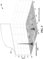
- Fig. 3 depicted is a graphical illustration 300 of exemplary radar data and an example conversion function 302 that can be applied to the radar data.
- the magnitudes e.g., gains
- Fig. 3 illustrates a magnitude map of the actual radar returns.
- the conversion function 302 can be determined from the magnitude map of the actual radar returns.
- Fig. 4 illustrates an exemplary methodology relating to calibrating a radar sensor. While the methodology is shown and described as being a series of acts that are performed in a sequence, it is to be understood and appreciated that the methodology is not limited by the order of the sequence. For example, some acts can occur in a different order than what is described herein. In addition, an act can occur concurrently with another act. Further, in some instances, not all acts may be required to implement a methodology described herein.
- the acts described herein may be computer-executable instructions that can be implemented by one or more processors and/or stored on a computer-readable medium or media.
- the computer-executable instructions can include a routine, a sub-routine, programs, a thread of execution, and/or the like.
- results of acts of the methodologies can be stored in a computer-readable medium, displayed on a display device, and/or the like.
- Fig. 4 illustrates a flow chart of an exemplary method 400 for calibrating the radar sensor 100.
- the radar sensor 100 transmits radar signals from the transmit antenna 102 into the operating environment and receives radar returns at the receive antenna 104 from a plurality of objects in the operating environment. At least a subset of the objects are known static objects.
- the radar returns are processed within the radar sensor 100 by the signal processing component 112 and analyzed by the radar analysis component 110 as described above.
- the radar sensor position module 118 identifies the position and the orientation of the radar sensor 100 at the time the radar signal was transmitted.
- the comparison module 120 identifies the expected reflectance values for each of the selected known static objects in the radar returns. To do so, the comparison module 120 uses the location of the known static objects from the radar returns, as determined by the radar analysis component 110 of the radar sensor 100, the position and orientation of the radar sensor 100 associated with the radar return as determined by the radar sensor position module 118, and the expected reflectance value for the known static objects from the radar map module 116 based on the position and the orientation of the radar sensor 100.
- the correction module 122 compares the actual magnitude of each the plurality of selected known static objects from the radar return with the expected reflectance value for each of those known static objects as identified by the comparison module 120. The correction module 122 then uses this set of data to determine a conversion function (e.g., a polynomial equation) that fits the dataset. At step 410, the correction module 122 then uses the conversion function to adjust the output of the radar sensor 100 (i.e., calibrate the sensor) so that the output is an estimated reflectance value that more closely resembles the expected reflectance values. The radar sensor output can be repeatedly or continuously adjusted in this manner during operation of the radar sensor 100. Furthermore, a faulty radar sensor can be easily and timely identified based on the difference between the magnitude of the radar return and the expected reflectance value. A large difference can be flagged by the radar system 202 as being indicative of a faulty radar sensor.
- a conversion function e.g., a polynomial equation
- the computing device 500 may be or include the computing system 212.
- the computing device 500 includes at least one processor 502 that executes instructions that are stored in a memory 504.
- the instructions may be, for instance, instructions for implementing functionality described as being carried out by one or more modules, components, or systems discussed above or instructions for implementing one or more of the methods described above.
- the processor 502 may be a GPU, a plurality of GPUs, a CPU, a plurality of CPUs, a multi-core processor, etc.
- the processor 502 may access the memory 504 by way of a system bus 506.
- the memory 504 may also store radar data, beamformed radar data, neural network configurations, etc.
- the computing device 500 additionally includes a data store 508 that is accessible by the processor 502 by way of the system bus 506.
- the data store 508 may include executable instructions, radar data, beamformed radar data, embeddings of these data in latent spaces, etc.
- the computing device 500 also includes an input interface 510 that allows external devices to communicate with the computing device 500. For instance, the input interface 510 may be used to receive instructions from an external computing device, etc.
- the computing device 500 also includes an output interface 512 that interfaces the computing device 500 with one or more external devices. For example, the computing device 500 may transmit control signals to the vehicle propulsion system 206, the braking system 208, and/or the steering system 210 by way of the output interface 512.
- the computing device 500 may be a distributed system. Thus, for instance, several devices may be in communication by way of a network connection and may collectively perform tasks described as being performed by the computing device 500.
- Computer-readable media includes computer-readable storage media.
- a computer-readable storage media can be any available storage media that can be accessed by a computer.
- such computer-readable storage media can comprise RAM, ROM, EEPROM, CD-ROM or other optical disk storage, magnetic disk storage or other magnetic storage devices, or any other medium that can be used to store desired program code in the form of instructions or data structures and that can be accessed by a computer.
- Disk and disc include compact disc (CD), laser disc, optical disc, digital versatile disc (DVD), floppy disk, and Blu-ray disc (BD), where disks usually reproduce data magnetically and discs usually reproduce data optically with lasers. Further, a propagated signal is not included within the scope of computer-readable storage media.
- Computer-readable media also includes communication media including any medium that facilitates transfer of a computer program from one place to another. A connection, for instance, can be a communication medium.
- the software is transmitted from a website, server, or other remote source using a coaxial cable, fiber optic cable, twisted pair, digital subscriber line (DSL), or wireless technologies such as infrared, radio, and microwave
- coaxial cable, fiber optic cable, twisted pair, DSL, or wireless technologies such as infrared, radio and microwave
- the coaxial cable, fiber optic cable, twisted pair, DSL, or wireless technologies such as infrared, radio and microwave
- the functionally described herein can be performed, at least in part, by one or more hardware logic components.
- illustrative types of hardware logic components include FPGAs, ASICs, Application-specific Standard Products (ASSPs), SOCs, Complex Programmable Logic Devices (CPLDs), etc.
- a method of calibrating a radar sensor includes transmitting a radar signal into an operating environment.
- the method also includes receiving radar returns from a plurality of objects in the operating environment based on the radar signal sent, each of the radar returns having a magnitude associated with each of the plurality of objects, and at least a subset of the objects are known static objects.
- the method additionally includes identifying a location and orientation of the radar sensor when the radar signal was sent.
- the method further includes identifying an expected reflectance value for each of the plurality of known static objects.
- the method also includes calculating a conversion function configured to adjust the magnitude associated with each of the radar returns from the known static objects to an estimated reflectance value based on the expected reflectance value for each of the plurality of known static objects.
- the method further includes adjusting an output of the radar sensor based on the conversion function.
- identifying expected reflectance values for each of the plurality of known static objects further comprises accessing a predetermined radar map of the operating environment of the radar sensor comprising the plurality of known static objects, wherein the predetermined radar map identifies expected reflectance values for each of the plurality of known static objects.
- each of the plurality of known static objects is a static object in the operating environment.
- the expected reflectance values are a function of the location and orientation of the radar sensor.
- the predetermined radar map identifies the expected reflectance values for a set of known static objects in the operating environment.
- the conversion function is a polynomial equation.
- the conversion function is continuously updated during operation of the radar sensor based on receiving additional radar returns.
- the output of the radar sensor is continuously adjusted based on the conversion function during operation of the radar sensor.
- adjusting the output of the radar sensor based on the conversion function further comprises adjusting the magnitudes associated with each of the radar returns from the plurality of objects based on the conversion function.
- a radar sensor located in an operating environment includes a signal processing component configured to capture a plurality of radar returns from a plurality of objects in the operating environment, wherein the plurality of radar returns from the plurality of objects are captured based on a radar signal sent from the radar sensor, and at least a subset of the objects are known static objects.
- the radar sensor further includes a radar map module configured to access a predetermined radar map of radar data for the plurality of known static objects in the operating environment.
- the radar sensor also includes a radar sensor position module configured to identify a location and orientation of the radar sensor when the radar signal was sent.
- the radar sensor includes a comparison module configured to identify expected reflectance values for each of the plurality of known static objects based on the location and orientation of the radar sensor. Moreover, the radar sensor includes a correction module configured to calculate a conversion function to adjust a magnitude of each of the radar returns for the known static objects to an estimated reflectance value based on the expected reflectance values for each of the plurality of known static objects, the correction module further configured to adjust an output of the radar sensor based on the conversion function.
- each of the plurality of known static objects is a static object in the operating environment.
- the conversion function is a polynomial equation.
- the correction module continuously updates the conversion function during operation of the radar sensor based on the radar returns.
- the correction module continuously adjusts the output of the radar sensor based on the conversion function during operation of the radar sensor.
- adjusting the output of the radar sensor based on the conversion function further comprises adjusting the magnitudes associated with each of the radar returns from the plurality of objects based on the conversion function.
- an autonomous vehicle for traversing an operating environment includes a radar sensor.
- the operating environment includes a plurality of objects that are detectable by the radar sensor, wherein the radar sensor captures a plurality of radar returns from the plurality of objects based on a radar signal sent from the radar sensor, and at least a subset of the objects are known static objects.
- the autonomous vehicle also includes a computing system in communication with the radar sensor, where the computing system includes a radar map module configured to access a predetermined radar map of radar data for the plurality of known static objects in the operating environment.
- the computing system also includes a radar sensor position module configured to identify a location and orientation of the radar sensor when the radar signal was sent.
- the computing system further includes a comparison module configured to identify expected reflectance values for each of the plurality of known static objects based on the location and orientation of the radar sensor. Moreover, the computing system includes a correction module configured to calculate a conversion function to adjust a magnitude of each of the radar returns for the known static objects to an estimated reflectance value based on the expected reflectance values for each of the plurality of known static objects, the correction module further configured to adjust an output of the radar sensor based on the conversion function.
- each of the plurality of known static objects is a static object in the operating environment.
- the conversion function is a polynomial equation.
- the correction module continuously updates the conversion function during operation of the radar sensor based on the radar returns.
- the correction module continuously adjusts the output of the radar sensor based on the conversion function during operation of the radar sensor.
Landscapes
- Engineering & Computer Science (AREA)
- Radar, Positioning & Navigation (AREA)
- Remote Sensing (AREA)
- Physics & Mathematics (AREA)
- Computer Networks & Wireless Communication (AREA)
- General Physics & Mathematics (AREA)
- Electromagnetism (AREA)
- Radar Systems Or Details Thereof (AREA)
Abstract
Description
- An autonomous vehicle is a motorized vehicle that can navigate without a human driver. An exemplary autonomous vehicle includes a plurality of sensor systems, such as, but not limited to, a camera sensor system, a light detection and ranging (LIDAR) sensor system, or a radio detection and ranging (RADAR) sensor system, amongst others. The autonomous vehicle operates (i.e., steering, braking, propulsion, etc.) based upon sensor signals from the sensor systems.
- Some vehicles use multiple sensors of the same given type, such as multiple radar sensors, so that the vehicle has a larger field of view than a single such sensor would ordinarily provide. Since the autonomous vehicle depends on the sensor systems to provide information of the surrounding environment to operate safely without a human driver, it is imperative that the sensor systems provide accurate information. For a variety of reasons, such as, but not limited to, differences between sensors, obstructed views of the environment around the vehicle, manufacturing defects or other discrepancies in sensors, in vehicles, and/or in mounting hardware, and prolonged exposure to the environment, sensor measurements may not be an accurate representative of an environment nearby the vehicle.
- To ensure accuracy and safety, sensor systems, such as radar sensor systems, should be calibrated often.
- The following is a brief summary of subject matter that is described in greater detail herein. This summary is not intended to be limiting as to the scope of the claims.
- Described herein are various technologies relating to the calibration of radar sensors. An exemplary implementation of a method of calibrating a radar sensor includes transmitting a radar signal into an operating environment and receiving radar returns from a plurality of objects in the operating environment based on the radar signal sent. Each of the radar returns has a magnitude associated with each of the plurality of objects. At least a subset of the objects are known static objects (e.g., stop signs, bridges, buildings, etc.). The method further includes identifying a location and orientation of the radar sensor when the signal was sent and identifying expected reflectance values for each of the plurality of known static objects. Based on the location and orientation of the radar sensor and the expected reflectance values, a conversion function is calculated to adjust the magnitudes associated with each of the radar returns from the known static objects to an estimated reflectance value. The output of the radar sensor is then adjusted based on the conversion function. In an exemplary implementation, identifying expected reflectance values for each of the plurality of known static objects includes accessing a predetermined radar map of the operating environment of the radar sensor containing the plurality of known static objects. The predetermined radar map identifies expected reflectance values for each of the known static objects.
- In an exemplary implementation, a radar sensor coupled to an autonomous vehicle is located in an operating environment. The radar sensor can include a signal processing component configured to capture a plurality of radar returns from the one or more objects in the environment. At least a subset of the objects are known static objects. The system further includes a radar map module configured to access a predetermined radar map of the radar data for the known static objects in the operating environment, a radar sensor position module configured to identify a location and orientation of the radar sensor when the signal was sent, and a comparison module configured to identify expected reflectance values for each of the known static objects based on the identified location and orientation of the radar sensor. The system also includes a correction module configured to calculate a conversion function to adjust the magnitudes of each of the radar returns from the known static objects to an estimated reflectance value based on the expected reflectance values for each of the known static objects and to adjust an output of the radar sensor based on the conversion function.
- The above summary presents a simplified summary in order to provide a basic understanding of some aspects of the systems and/or methods discussed herein. This summary is not an extensive overview of the systems and/or methods discussed herein. It is not intended to identify key/critical elements or to delineate the scope of such systems and/or methods. Its sole purpose is to present some concepts in a simplified form as a prelude to the more detailed description that is presented later.
-
-
Fig. 1 is a functional block diagram of an exemplary radar sensor. -
Fig. 2 is a functional block diagram of an exemplary autonomous vehicle. -
Fig. 3 is a graphical illustration of exemplary radar data and an example conversion function that can be applied to the radar data. -
Fig. 4 is a flow diagram that illustrates an exemplary methodology for calibrating a radar sensor. -
Fig. 5 is an exemplary computing system. - Various technologies pertaining to the calibration of a radar sensor are described herein. With more particularity, technologies described herein relate to calibrating a radar sensor using a radar map of known static objects in an operational environment of the radar sensor. In the following description, for purposes of explanation, numerous specific details are set forth in order to provide a thorough understanding of one or more aspects. It may be evident, however, that such aspect(s) may be practiced without these specific details. In other instances, well-known structures and devices are shown in block diagram form in order to facilitate describing one or more aspects. Further, it is to be understood that functionality that is described as being carried out by certain system components may be performed by multiple components. Similarly, for instance, a component may be configured to perform functionality that is described as being carried out by multiple components.
- Moreover, the term "or" is intended to mean an inclusive "or" rather than an exclusive "or." That is, unless specified otherwise, or clear from the context, the phrase "X employs A or B" is intended to mean any of the natural inclusive permutations. That is, the phrase "X employs A or B" is satisfied by any of the following instances: X employs A; X employs B; or X employs both A and B. In addition, the articles "a" and "an" as used in this application and the appended claims should generally be construed to mean "one or more" unless specified otherwise or clear from the context to be directed to a singular form.
- Further, as used herein, the terms "component", "system", and "module" are intended to encompass computer-readable data storage that is configured with computer-executable instructions that cause certain functionality to be performed when executed by a processor. The computer-executable instructions may include a routine, a function, or the like. It is also to be understood that a component or system may be localized on a single device or distributed across several devices. Further, as used herein, the term "exemplary" is intended to mean serving as an illustration or example of something and is not intended to indicate a preference.
-
Fig. 1 is a high-level illustration of anexemplary radar sensor 100. Theradar sensor 100 may be anysuitable radar sensor 100. In the illustrated implementation, theradar sensor 100 includes atransmit antenna 102, areceive antenna 104, and aradar computing component 106. Briefly, theradar computing component 106 is configured to prepare radar signals that are transmitted by thetransmit antenna 102, and to compute object solutions indicating estimated positions and/or velocities of objects based upon radar returns received by the receiveantenna 104. In exemplary implementations, various components of theradar sensor 100 can be integrated as a same system-on-a-chip (SoC). In various implementations, theradar sensor 100 can be employed on a vehicle, such as a land vehicle, an aircraft, to identify positions and velocities of objects in the operational environment of the vehicle. - The
radar computing component 106 comprises asignal generator component 108 that prepares radar signals for transmission by way of thetransmit antenna 102 and aradar analysis component 110 that analyzes the radar data received by the receiveantenna 104. Theradar sensor 100 is configured to repeatedly, or continuously, transmit radar signals (e.g., pulse sequences) by way of thetransmit antenna 102, and to receive radar returns repeatedly, or continuously, by way of the receiveantenna 104. - In exemplary implementations, the radar returns received by the receive
antenna 104 comprise reflections, from objects in the operational environment of theradar sensor 100, of radar signals emitted by thetransmit antenna 102. Responsive to receipt of radar returns from the operational environment of theradar sensor 100, the receiveantenna 104 outputs an electrical signal that is indicative of the received radar returns. This electrical signal is referred to herein as a radar signal and is transmitted along one or more transmission lines in theradar sensor 100, as distinct from radar returns that are received by the receiveantenna 104 as radiated signals propagating through air or free space in the operational environment of theradar sensor 100. - The
radar sensor 100 further includes asignal processing component 112. Thesignal processing component 112 receives a radar signal from thereceive antenna 104. Thesignal processing component 112, for instance, can capture a plurality of radar returns from a plurality of objects in an operating environment. Thesignal processing component 112 is configured to perform various analog signal processing operations over radar signals received from thereceive antenna 104. By way of example, and not limitation, thesignal processing component 112 can perform various mixing, filtering, and amplification operations on radar signals output by the receiveantenna 104. Thesignal processing component 112 can be configured to perform a variety of these signal processing operations (e.g., mixing) based further upon a radar signal transmitted by the transmitantenna 102. - The
radar computing component 106 receives the radar data via thesignal processing component 112. Theradar analysis component 110 of theradar computing component 106 is configured to determine properties of the each of the objects in the operational environment of theradar sensor 100 based upon the radar data. In a non-limiting example, theradar analysis component 110 can compute a range, a bearing, and/or a velocity of an object in the operational environment of theradar sensor 100 based upon the radar data. Theradar sensor 100 also includes asensor output 114 indicative of the analyzed radar data. - Various technologies described herein are suitable for use in connection with an autonomous vehicle (AV) that employs a radar system to facilitate navigation about roadways. Referring to
Fig. 2 , anexemplary AV 200 is illustrated, wherein theAV 200 can navigate about roadways without human conduction based upon sensor signals output by sensor systems of theAV 200. TheAV 200 includes a plurality of sensor systems 202-204. The sensor systems 202-204 may be of different types. The sensor systems 202-204 include aradar sensor system 202 and disparate sensor system(s) 204 (e.g., substantially any number and types of sensor systems in addition to the radar sensor system 202). Theradar sensor system 202 can be or include the radar sensor 100 (or a plurality of radar sensors each similar to the radar sensor 100). The disparate sensor system(s) 204, for example, can include a lidar sensor system, a camera (image) system, and/or a sonar system. Other exemplary sensor systems that can additionally or alternatively be included in the disparate sensor system(s) 204 include GPS sensor systems, inertial sensor systems, infrared sensor systems, and the like. The various sensor systems 202-204 are arranged about theAV 200. The sensor systems 202-204 are configured to repeatedly (e.g., continuously, or periodically) output sensor data that is representative of objects and conditions in the driving environment of theAV 200. - The
AV 200 further includes several mechanical systems that are used to effectuate appropriate motion of theAV 200. For instance, the mechanical systems can include but are not limited to, avehicle propulsion system 206, abraking system 208, and asteering system 210. Thevehicle propulsion system 206 may be an electric engine, a combustion engine, or a combination thereof. Thebraking system 208 can include an engine brake, brake pads, actuators, a regenerative braking system, and/or any other suitable componentry that is configured to assist in decelerating theAV 200. Thesteering system 210 includes suitable componentry that is configured to control the direction of movement of theAV 200. - The
AV 200 additionally comprises acomputing system 212 that is in communication with the sensor systems 202-204 and is further in communication with thevehicle propulsion system 206, thebraking system 208, and thesteering system 210. Thecomputing system 212 includes aprocessor 214 andmemory 216 that includes computer-executable instructions that are executed by theprocessor 214. In an example, theprocessor 214 can be or include a graphics processing unit (GPU), a plurality of GPUs, a central processing unit (CPU), a plurality of CPUs, an application-specific integrated circuit (ASIC), a microcontroller, a programmable logic controller (PLC), a field programmable gate array (FPGA), or the like. - The
memory 216 comprises alocalization system 218, aperception system 220, aplanning system 222, and acontrol system 224. Briefly, thelocalization system 218 is configured to determine a local position of theAV 200. Theperception system 220 is configured to identify the presence of objects and/or characteristics of objects in the driving environment of theAV 200 based upon sensor data output by the sensor systems 202-204. Theplanning system 222 is configured to plan a route and/or a maneuver of theAV 200 based upon data pertaining to objects in the driving environment that are output by theperception system 220. Thecontrol system 224 is configured to control the mechanical systems 206-210 of theAV 200 to effectuate appropriate motion to cause theAV 200 to execute a maneuver planned by theplanning system 222. - The
perception system 220 is configured to identify objects in proximity to theAV 200 that are captured in sensor signals output by the sensor systems 202-204. By way of example, theperception system 220 can be configured to identify the presence of an object in the driving environment of theAV 200 based upon images generated by a camera system included in the disparate sensor system(s) 204. In another example, theperception system 220 can be configured to determine a presence and position of an object based upon radar data output by theradar sensor system 202. In exemplary implementations, theradar sensor system 202 can include one ormore radar sensors 100. In such implementations, theperception system 220 can be configured to identify a position of an object in the driving environment of theAV 200 based upon the estimated range output by theradar sensor 100. - The
AV 200 can be included in a fleet of AVs that are in communication with a common server computing system. In these implementations, the server computing system can control the fleet of AVs such that radar sensor systems of AVs operating in a same driving environment (e.g., within line of sight of one another, or within a threshold distance of one another) employ different pulse sequence carrier frequencies. In an exemplary implementation, a radar sensor system of a first AV can be controlled so as not to transmit pulse sequences having same center frequencies as pulse sequences transmitted by a radar sensor system of a second AV at the same time. In further implementations, the radar sensor system of the first AV can be controlled to transmit pulse sequences in a different order than a radar sensor system of a second AV. For instance, the radar sensor system of the first AV can be configured to transmit a set of pulse sequences at four different center frequencies A, B, C, and D in an order A, B, C, D. The radar sensor system of the second AV can be configured to transmit pulse sequences using a same set of center frequencies in a frequency order B, A, D, C. Such configurations can mitigate the effects of interference when multiple AVs that employ radar sensor systems are operating in a same driving environment. - Reference is again made to
Fig. 1 . Theradar sensor 100 is calibrated with the use of a radar map of the environment that theradar sensor 100 is operating in (i.e., the operating environment). To that end, in an exemplary implementation, theradar sensor 100 can include aradar map module 116. Theradar map module 116 is configured to access a predetermined radar map of radar data for known static objects in the operating environment. Examples of known static objects that can be represented in the predetermined radar map can include signs, buildings, bridges, or substantially any other static object that remains fixed in the environment. According to an example, theradar sensor 100 can include the predetermined radar map, which can be accessed by theradar map module 116. Pursuant to another example, thecomputing system 212 of theautonomous vehicle 200 can store the predetermined radar map (e.g., the radar map can be stored in a data store of the computing system 212); following this example, theradar map module 116 can access the predetermined radar map retained by thecomputing system 212 of theautonomous vehicle 200. In some implementations, the predetermined radar map may only include a select group of known static objects in the operating environment for use in calibrating theradar sensor 100. - The radar map includes expected radar reflectance values for a plurality of known static objects in the operating environment as a function of range and angle of the
radar sensor 100. For example, the localized position and orientation of the radar sensor within the map is defined by coordinates X1, Y1, Z1 with three rotation angles (RX, RY, RZ (i.e., yaw, pitch, and roll). For a static object at map coordinates X2, Y2, the radar map will contain an expected reflectance value that a radar sensor at coordinates X1, Y1, Z1, and orientation RX, RY, RZ should receive from the given static object. In this way, the radar map provides information regarding how the reflectance value is impacted by the range from the object and by the orientation of the radar sensor. - The radar map may be created, for example, by gathering radar data from radar systems of AVs as those AVs drive around the operating environment (e.g., town, city, etc.). While driving around the operating environment, the radar system of each of the AVs records the position and orientation of the radar sensors of the radar systems of the AVs and records the magnitude of the radar return and location of the object generating the return.
- The
radar sensor 100 further includes a radarsensor position module 118 configured to identify a location and orientation of theradar sensor 100. The radarsensor position module 118 may utilize any suitable sensing devices for determining the position and the orientation of theradar sensor 100 at a given time, such as GPS sensor systems and inertial sensor systems, which may already be associated with theradar sensor system 202 or theAV 200. Additionally or alternatively, the radarsensor position module 118 can receive information specifying the local position of theAV 200 from thelocalization system 218 of theAV 200; the radarsensor position module 118 can further determine the position and orientation of theradar sensor 100 based at least in part on the information specifying the local position of theAV 200. Since range and orientation of theradar sensor 100 impact the magnitude of the radar return, the range and orientation information provided by the radarsensor position module 118 is used to calibrate theradar sensor 100 as described below. - The
radar sensor 100 further includes a comparison module 120 configured to identify expected reflectance values for each of the known static objects based on the identified location and orientation of theradar sensor 100. The comparison module 120 is configured to communicate with theradar map module 116 and the radarsensor position module 118 for this purpose. In particular, the comparison module 120 identifies the location of an object from the radar returns. The comparison module 120 then communicates with the radarsensor position module 118 to identify the position and orientation of theradar sensor 100 associated with the radar return (i.e., the position and orientation of theradar sensor 100 when that radar signal, associated with the radar return, was sent from the radar sensor). The comparison module 120 then communicates with theradar map module 116 to identify the expected reflectance value for the object based on the position and the orientation identified from the radarsensor position module 118. - The
radar sensor 100 further includes acorrection module 122. Thecorrection module 122 is configured to calculate a conversion function to adjust the magnitudes associated with each of the radar returns of the known static objects to estimated reflectance values based on the expected reflectance values for each of the known static objects. For example, thecorrection module 122 takes the actual radar return magnitudes for the known static objects and the expected reflectance value for each of the known static objects, as determined by the comparison module 120, and determines a conversion function (e.g., curve fitting) to adjust the actual radar return magnitudes to values that approximate the expected values. In an exemplary implementation, the conversion function is in the form of a polynomial equation, which can be any order polynomial equation suitable for use as a conversion function. - The
correction module 122 is also configured to adjust the output of theradar sensor 100 based on the conversion function. For example, thesensor output 114 may represent a magnitude of the radar signal. Thecorrection module 122 may use the conversion function to adjust the magnitude of thesensor output 114. This adjusted sensor output is then used by thecomputing system 212 of theAV 200 during operation. Thus, radar returns from non-static objects or objects other than those represented in the radar map can be adjusted by thecorrection module 122 using the conversion function. Accordingly, thecorrection module 122 can adjust the magnitudes associated with each of the radar returns from the plurality of objects (i.e., the known static object(s) as well as other object(s) such as non-static object(s) or objects other than those represented in the radar map) based on the conversion function. - In various embodiments, it is contemplated that the
memory 216 of thecomputing system 212 of theautonomous vehicle 200 can additionally or alternatively include one or more of theradar map module 116, the radarsensor position module 118, the comparison module 120, and/or thecorrection module 112. - Referring to
Fig. 3 , depicted is agraphical illustration 300 of exemplary radar data and anexample conversion function 302 that can be applied to the radar data. As noted above, the magnitudes (e.g., gains) associated with the actual radar returns for the known static objects can be obtained. For instance,Fig. 3 illustrates a magnitude map of the actual radar returns. Further, utilizing the approaches described herein, theconversion function 302 can be determined from the magnitude map of the actual radar returns. -
Fig. 4 illustrates an exemplary methodology relating to calibrating a radar sensor. While the methodology is shown and described as being a series of acts that are performed in a sequence, it is to be understood and appreciated that the methodology is not limited by the order of the sequence. For example, some acts can occur in a different order than what is described herein. In addition, an act can occur concurrently with another act. Further, in some instances, not all acts may be required to implement a methodology described herein. - Moreover, the acts described herein may be computer-executable instructions that can be implemented by one or more processors and/or stored on a computer-readable medium or media. The computer-executable instructions can include a routine, a sub-routine, programs, a thread of execution, and/or the like. Still further, results of acts of the methodologies can be stored in a computer-readable medium, displayed on a display device, and/or the like.
-
Fig. 4 illustrates a flow chart of anexemplary method 400 for calibrating theradar sensor 100. In particular, atstep 402 during operation of theradar sensor system 202, theradar sensor 100 transmits radar signals from the transmitantenna 102 into the operating environment and receives radar returns at the receiveantenna 104 from a plurality of objects in the operating environment. At least a subset of the objects are known static objects. The radar returns are processed within theradar sensor 100 by thesignal processing component 112 and analyzed by theradar analysis component 110 as described above. Atstep 404, the radarsensor position module 118 identifies the position and the orientation of theradar sensor 100 at the time the radar signal was transmitted. - At
step 406, the comparison module 120 identifies the expected reflectance values for each of the selected known static objects in the radar returns. To do so, the comparison module 120 uses the location of the known static objects from the radar returns, as determined by theradar analysis component 110 of theradar sensor 100, the position and orientation of theradar sensor 100 associated with the radar return as determined by the radarsensor position module 118, and the expected reflectance value for the known static objects from theradar map module 116 based on the position and the orientation of theradar sensor 100. - At
step 408, thecorrection module 122 compares the actual magnitude of each the plurality of selected known static objects from the radar return with the expected reflectance value for each of those known static objects as identified by the comparison module 120. Thecorrection module 122 then uses this set of data to determine a conversion function (e.g., a polynomial equation) that fits the dataset. Atstep 410, thecorrection module 122 then uses the conversion function to adjust the output of the radar sensor 100 (i.e., calibrate the sensor) so that the output is an estimated reflectance value that more closely resembles the expected reflectance values. The radar sensor output can be repeatedly or continuously adjusted in this manner during operation of theradar sensor 100. Furthermore, a faulty radar sensor can be easily and timely identified based on the difference between the magnitude of the radar return and the expected reflectance value. A large difference can be flagged by theradar system 202 as being indicative of a faulty radar sensor. - Referring now to
Fig. 5 , a high-level illustration of anexemplary computing device 500 that can be used in accordance with the systems and methodologies disclosed herein is illustrated. For instance, thecomputing device 500 may be or include thecomputing system 212. Thecomputing device 500 includes at least oneprocessor 502 that executes instructions that are stored in amemory 504. The instructions may be, for instance, instructions for implementing functionality described as being carried out by one or more modules, components, or systems discussed above or instructions for implementing one or more of the methods described above. Theprocessor 502 may be a GPU, a plurality of GPUs, a CPU, a plurality of CPUs, a multi-core processor, etc. Theprocessor 502 may access thememory 504 by way of asystem bus 506. In addition to storing executable instructions, thememory 504 may also store radar data, beamformed radar data, neural network configurations, etc. - The
computing device 500 additionally includes adata store 508 that is accessible by theprocessor 502 by way of thesystem bus 506. Thedata store 508 may include executable instructions, radar data, beamformed radar data, embeddings of these data in latent spaces, etc. Thecomputing device 500 also includes aninput interface 510 that allows external devices to communicate with thecomputing device 500. For instance, theinput interface 510 may be used to receive instructions from an external computing device, etc. Thecomputing device 500 also includes anoutput interface 512 that interfaces thecomputing device 500 with one or more external devices. For example, thecomputing device 500 may transmit control signals to thevehicle propulsion system 206, thebraking system 208, and/or thesteering system 210 by way of theoutput interface 512. - Additionally, while illustrated as a single system, it is to be understood that the
computing device 500 may be a distributed system. Thus, for instance, several devices may be in communication by way of a network connection and may collectively perform tasks described as being performed by thecomputing device 500. - Various functions described herein can be implemented in hardware, software, or any combination thereof. If implemented in software, the functions can be stored on or transmitted over as one or more instructions or code on a computer-readable medium. Computer-readable media includes computer-readable storage media. A computer-readable storage media can be any available storage media that can be accessed by a computer. By way of example, and not limitation, such computer-readable storage media can comprise RAM, ROM, EEPROM, CD-ROM or other optical disk storage, magnetic disk storage or other magnetic storage devices, or any other medium that can be used to store desired program code in the form of instructions or data structures and that can be accessed by a computer. Disk and disc, as used herein, include compact disc (CD), laser disc, optical disc, digital versatile disc (DVD), floppy disk, and Blu-ray disc (BD), where disks usually reproduce data magnetically and discs usually reproduce data optically with lasers. Further, a propagated signal is not included within the scope of computer-readable storage media. Computer-readable media also includes communication media including any medium that facilitates transfer of a computer program from one place to another. A connection, for instance, can be a communication medium. For example, if the software is transmitted from a website, server, or other remote source using a coaxial cable, fiber optic cable, twisted pair, digital subscriber line (DSL), or wireless technologies such as infrared, radio, and microwave, then the coaxial cable, fiber optic cable, twisted pair, DSL, or wireless technologies such as infrared, radio and microwave are included in the definition of communication medium. Combinations of the above should also be included within the scope of computer-readable media.
- Alternatively, or in addition, the functionally described herein can be performed, at least in part, by one or more hardware logic components. For example, and without limitation, illustrative types of hardware logic components that can be used include FPGAs, ASICs, Application-specific Standard Products (ASSPs), SOCs, Complex Programmable Logic Devices (CPLDs), etc.
- Systems and methods have been described herein in accordance with at least the examples set forth below.
- (A1) In one aspect, a method of calibrating a radar sensor is disclosed herein, where the method includes transmitting a radar signal into an operating environment. The method also includes receiving radar returns from a plurality of objects in the operating environment based on the radar signal sent, each of the radar returns having a magnitude associated with each of the plurality of objects, and at least a subset of the objects are known static objects. The method additionally includes identifying a location and orientation of the radar sensor when the radar signal was sent. The method further includes identifying an expected reflectance value for each of the plurality of known static objects. The method also includes calculating a conversion function configured to adjust the magnitude associated with each of the radar returns from the known static objects to an estimated reflectance value based on the expected reflectance value for each of the plurality of known static objects. The method further includes adjusting an output of the radar sensor based on the conversion function.
- (A2) In some embodiments of the method of (A1), identifying expected reflectance values for each of the plurality of known static objects further comprises accessing a predetermined radar map of the operating environment of the radar sensor comprising the plurality of known static objects, wherein the predetermined radar map identifies expected reflectance values for each of the plurality of known static objects.
- (A3) In some embodiments of the method of (A2), each of the plurality of known static objects is a static object in the operating environment.
- (A4) In some embodiments of at least one of the methods of (A2)-(A3), the expected reflectance values are a function of the location and orientation of the radar sensor.
- (A5) In some embodiments of at least one of the method of (A2)-(A4), the predetermined radar map identifies the expected reflectance values for a set of known static objects in the operating environment.
- (A6) In some embodiments of at least one of the methods of (A1)-(A5), the conversion function is a polynomial equation.
- (A7) In some embodiments of at least one of the methods of (A1)-(A6), the conversion function is continuously updated during operation of the radar sensor based on receiving additional radar returns.
- (A8) In some embodiments of at least one of the methods of (A1)-(A7), the output of the radar sensor is continuously adjusted based on the conversion function during operation of the radar sensor.
- (A9) In some embodiments of at least one of the methods of (A1)-(A8), adjusting the output of the radar sensor based on the conversion function further comprises adjusting the magnitudes associated with each of the radar returns from the plurality of objects based on the conversion function.
- (B1) In another aspect, a radar sensor located in an operating environment is disclosed herein, where the radar sensor includes a signal processing component configured to capture a plurality of radar returns from a plurality of objects in the operating environment, wherein the plurality of radar returns from the plurality of objects are captured based on a radar signal sent from the radar sensor, and at least a subset of the objects are known static objects. The radar sensor further includes a radar map module configured to access a predetermined radar map of radar data for the plurality of known static objects in the operating environment. The radar sensor also includes a radar sensor position module configured to identify a location and orientation of the radar sensor when the radar signal was sent. Additionally, the radar sensor includes a comparison module configured to identify expected reflectance values for each of the plurality of known static objects based on the location and orientation of the radar sensor. Moreover, the radar sensor includes a correction module configured to calculate a conversion function to adjust a magnitude of each of the radar returns for the known static objects to an estimated reflectance value based on the expected reflectance values for each of the plurality of known static objects, the correction module further configured to adjust an output of the radar sensor based on the conversion function.
- (B2) In some embodiments of the radar sensor of (B1), each of the plurality of known static objects is a static object in the operating environment.
- (B3) In some embodiments of at least one of the radar sensors of (B1)-(B2), the conversion function is a polynomial equation.
- (B4) In some embodiments of at least one of the radar sensors of (B1)-(B3), the correction module continuously updates the conversion function during operation of the radar sensor based on the radar returns.
- (B5) In some embodiments of at least one of the radar sensors of (B1)-(B4), the correction module continuously adjusts the output of the radar sensor based on the conversion function during operation of the radar sensor.
- (B6) In some embodiments of at least one of the radar sensors of (Bl)-(B5), adjusting the output of the radar sensor based on the conversion function further comprises adjusting the magnitudes associated with each of the radar returns from the plurality of objects based on the conversion function.
- (C1) In another aspect, an autonomous vehicle for traversing an operating environment is disclosed herein, where the autonomous vehicle includes a radar sensor. The operating environment includes a plurality of objects that are detectable by the radar sensor, wherein the radar sensor captures a plurality of radar returns from the plurality of objects based on a radar signal sent from the radar sensor, and at least a subset of the objects are known static objects. The autonomous vehicle also includes a computing system in communication with the radar sensor, where the computing system includes a radar map module configured to access a predetermined radar map of radar data for the plurality of known static objects in the operating environment. The computing system also includes a radar sensor position module configured to identify a location and orientation of the radar sensor when the radar signal was sent. The computing system further includes a comparison module configured to identify expected reflectance values for each of the plurality of known static objects based on the location and orientation of the radar sensor. Moreover, the computing system includes a correction module configured to calculate a conversion function to adjust a magnitude of each of the radar returns for the known static objects to an estimated reflectance value based on the expected reflectance values for each of the plurality of known static objects, the correction module further configured to adjust an output of the radar sensor based on the conversion function.
- (C2) In some embodiments of the autonomous vehicle of (C1), each of the plurality of known static objects is a static object in the operating environment.
- (C3) In some embodiments of at least one of the autonomous vehicles of (C1)-(C2), the conversion function is a polynomial equation.
- (C4) In some embodiments of at least one of the autonomous vehicles of (C1)-(C3), the correction module continuously updates the conversion function during operation of the radar sensor based on the radar returns.
- (C5) In some embodiments of at least one of the autonomous vehicles of (C1)-(C4), the correction module continuously adjusts the output of the radar sensor based on the conversion function during operation of the radar sensor.
- What has been described above includes examples of one or more implementations. It is, of course, not possible to describe every conceivable modification and alteration of the above devices or methodologies for purposes of describing the aforementioned aspects, but one of ordinary skill in the art can recognize that many further modifications and permutations of various aspects are possible. Accordingly, the described aspects are intended to embrace all such alterations, modifications, and variations that fall within the spirit and scope of the appended claims. Furthermore, to the extent that the term "includes" is used in either the detailed description or the claims, such term is intended to be inclusive in a manner similar to the term "comprising" as "comprising" is interpreted when employed as a transitional word in a claim.
Claims (15)
- A method of calibrating a radar sensor, comprising:transmitting a radar signal into an operating environment;receiving radar returns from a plurality of objects in the operating environment based on the radar signal sent, each of the radar returns having a magnitude associated with each of the plurality of objects, and at least a subset of the objects are known static objects;identifying a location and orientation of the radar sensor when the radar signal was sent;identifying an expected reflectance value for each of the plurality of known static objects;calculating a conversion function configured to adjust the magnitude associated with each of the radar returns from the known static objects to an estimated reflectance value based on the expected reflectance value for each of the plurality of known static objects; andadjusting an output of the radar sensor based on the conversion function.
- The method according to claim 1, wherein identifying expected reflectance values for each of the plurality of known static objects further comprises accessing a predetermined radar map of the operating environment of the radar sensor comprising the plurality of known static objects, wherein the predetermined radar map identifies expected reflectance values for each of the plurality of known static objects.
- The method according to claim 2, wherein each of the plurality of known static objects is a static object in the operating environment.
- The method according to at least one of claims 2 to 3, wherein the expected reflectance values are a function of the location and orientation of the radar sensor.
- The method according to at least one of claims 2 to 4, wherein the predetermined radar map identifies the expected reflectance values for a set of known static objects in the operating environment.
- The method according to at least one of claims 1 to 5, wherein the conversion function is a polynomial equation.
- The method according to at least one of claims 1 to 6, wherein the conversion function is continuously updated during operation of the radar sensor based on receiving additional radar returns.
- The method according to at least one of claims 1 to 7, wherein the output of the radar sensor is continuously adjusted based on the conversion function during operation of the radar sensor.
- The method according to at least one of claims 1 to 8, wherein adjusting the output of the radar sensor based on the conversion function further comprises adjusting the magnitudes associated with each of the radar returns from the plurality of objects based on the conversion function.
- A radar sensor located in an operating environment, the radar sensor comprising:a signal processing component configured to capture a plurality of radar returns from a plurality of objects in the operating environment, wherein the plurality of radar returns from the plurality of objects are captured based on a radar signal sent from the radar sensor, and at least a subset of the objects are known static objects;a radar map module configured to access a predetermined radar map of radar data for the plurality of known static objects in the operating environment;a radar sensor position module configured to identify a location and orientation of the radar sensor when the radar signal was sent;a comparison module configured to identify expected reflectance values for each of the plurality of known static objects based on the location and orientation of the radar sensor; anda correction module configured to calculate a conversion function to adjust a magnitude of each of the radar returns for the known static objects to an estimated reflectance value based on the expected reflectance values for each of the plurality of known static objects, the correction module further configured to adjust an output of the radar sensor based on the conversion function.
- The radar sensor according to claim 10, wherein each of the plurality of known static objects is a static object in the operating environment.
- The radar sensor according to at least one of claims 10 to 11, wherein the correction module continuously updates the conversion function during operation of the radar sensor based on the radar returns.
- The radar sensor according to at least one of claims 10 to 12, wherein the correction module continuously adjusts the output of the radar sensor based on the conversion function during operation of the radar sensor.
- The radar sensor according to at least one of claims 10 to 13, wherein adjusting the output of the radar sensor based on the conversion function further comprises adjusting the magnitudes associated with each of the radar returns from the plurality of objects based on the conversion function.
- An autonomous vehicle for traversing an operating environment, the autonomous vehicle comprising:a radar sensor, wherein the operating environment includes a plurality of objects that are detectable by the radar sensor, wherein the radar sensor captures a plurality of radar returns from the plurality of objects based on a radar signal sent from the radar sensor, and at least a subset of the objects are known static objects; anda computing system in communication with the radar sensor, wherein the computing system comprises:a radar map module configured to access a predetermined radar map of radar data for the plurality of known static objects in the operating environment;a radar sensor position module configured to identify a location and orientation of the radar sensor when the radar signal was sent;a comparison module configured to identify expected reflectance values for each of the plurality of known static objects based on the location and orientation of the radar sensor; anda correction module configured to calculate a conversion function to adjust a magnitude of each of the radar returns for the known static objects to an estimated reflectance value based on the expected reflectance values for each of the plurality of known static objects, the correction module further configured to adjust an output of the radar sensor based on the conversion function.
Priority Applications (2)
| Application Number | Priority Date | Filing Date | Title |
|---|---|---|---|
| EP22187754.1A EP4312053A1 (en) | 2022-07-29 | 2022-07-29 | Online magnitude calibration of radar sensor based on radar map of known objects |
| US17/899,724 US12546860B2 (en) | 2022-07-29 | 2022-08-31 | Magnitude calibration of radar sensor based on radar map of known objects |
Applications Claiming Priority (1)
| Application Number | Priority Date | Filing Date | Title |
|---|---|---|---|
| EP22187754.1A EP4312053A1 (en) | 2022-07-29 | 2022-07-29 | Online magnitude calibration of radar sensor based on radar map of known objects |
Publications (1)
| Publication Number | Publication Date |
|---|---|
| EP4312053A1 true EP4312053A1 (en) | 2024-01-31 |
Family
ID=82780952
Family Applications (1)
| Application Number | Title | Priority Date | Filing Date |
|---|---|---|---|
| EP22187754.1A Pending EP4312053A1 (en) | 2022-07-29 | 2022-07-29 | Online magnitude calibration of radar sensor based on radar map of known objects |
Country Status (2)
| Country | Link |
|---|---|
| US (1) | US12546860B2 (en) |
| EP (1) | EP4312053A1 (en) |
Citations (2)
| Publication number | Priority date | Publication date | Assignee | Title |
|---|---|---|---|---|
| US20190162820A1 (en) * | 2017-11-29 | 2019-05-30 | Delphi Technologies, Llc | Automated vehicle sensor calibration system |
| WO2021138204A1 (en) * | 2019-12-30 | 2021-07-08 | Lyft, Inc. | Systems and methods for blind online calibration of radar systems on a vehicle |
Family Cites Families (14)
| Publication number | Priority date | Publication date | Assignee | Title |
|---|---|---|---|---|
| RU2010136929A (en) * | 2008-02-04 | 2012-03-20 | Теле Атлас Норт Америка Инк. (Us) | METHOD FOR HARMONIZING A CARD WITH DETECTED SENSOR OBJECTS |
| US9719801B1 (en) * | 2013-07-23 | 2017-08-01 | Waymo Llc | Methods and systems for calibrating sensors using road map data |
| US9916703B2 (en) * | 2015-11-04 | 2018-03-13 | Zoox, Inc. | Calibration for autonomous vehicle operation |
| US9841763B1 (en) * | 2015-12-16 | 2017-12-12 | Uber Technologies, Inc. | Predictive sensor array configuration system for an autonomous vehicle |
| DE102016201250A1 (en) * | 2016-01-28 | 2017-08-03 | Conti Temic Microelectronic Gmbh | Method and device for determining the range of a sensor for a motor vehicle |
| DE102016221440A1 (en) * | 2016-11-02 | 2018-05-03 | Robert Bosch Gmbh | Method for diagnosing environmental sensor systems in vehicles |
| US11145146B2 (en) * | 2018-01-31 | 2021-10-12 | Mentor Graphics (Deutschland) Gmbh | Self-diagnosis of faults in an autonomous driving system |
| US10989562B2 (en) * | 2018-07-12 | 2021-04-27 | Toyota Research Institute, Inc. | Systems and methods for annotating maps to improve sensor calibration |
| DK180555B1 (en) * | 2018-12-10 | 2021-06-17 | Motional Ad Llc | Systems and methods for validating and calibrating sensors |
| DE102019200612B4 (en) * | 2019-01-18 | 2025-06-12 | Zf Friedrichshafen Ag | Apparatus and method for calibrating a multiple-input-multiple-output radar sensor |
| DE102019002487A1 (en) * | 2019-04-04 | 2020-10-08 | Daimler Ag | Method for checking a surroundings detection sensor of a vehicle and method for operating a vehicle |
| US11435440B2 (en) * | 2019-10-01 | 2022-09-06 | Qualcomm Incorporated | Vehicle-to-everything assisted dynamic calibration of automotive sensors |
| EP3825727A1 (en) * | 2019-11-20 | 2021-05-26 | Veoneer Sweden AB | Methods and systems for radar fault detection |
| US11714190B1 (en) * | 2021-05-11 | 2023-08-01 | Waymo Llc | Methods and systems for radar testing and development using hardware-in-the-loop with continuous integration |
-
2022
- 2022-07-29 EP EP22187754.1A patent/EP4312053A1/en active Pending
- 2022-08-31 US US17/899,724 patent/US12546860B2/en active Active
Patent Citations (2)
| Publication number | Priority date | Publication date | Assignee | Title |
|---|---|---|---|---|
| US20190162820A1 (en) * | 2017-11-29 | 2019-05-30 | Delphi Technologies, Llc | Automated vehicle sensor calibration system |
| WO2021138204A1 (en) * | 2019-12-30 | 2021-07-08 | Lyft, Inc. | Systems and methods for blind online calibration of radar systems on a vehicle |
Also Published As
| Publication number | Publication date |
|---|---|
| US20240036162A1 (en) | 2024-02-01 |
| US12546860B2 (en) | 2026-02-10 |
Similar Documents
| Publication | Publication Date | Title |
|---|---|---|
| EP2291677B1 (en) | Improvements in lidars | |
| KR20210111180A (en) | Method, apparatus, computing device and computer-readable storage medium for positioning | |
| US12523758B2 (en) | Systems and methods for online calibration in distributed aperture radar | |
| US10974730B2 (en) | Vehicle perception system on-line diangostics and prognostics | |
| CN111976722A (en) | Method and apparatus for controlling a vehicle including an autonomous control system | |
| CN114730016A (en) | Dynamic power throttling for rotary lidar | |
| CN113874756A (en) | Context-aware real-time power adjustment for steerable lidar | |
| CN115166791A (en) | Method and device for calibrating course angle of double GNSS (global navigation satellite system) antennas of intelligent driving vehicle | |
| US11919546B2 (en) | Systems and methods for estimating cuboids from LiDAR, map and image data | |
| US20210096254A1 (en) | Lidar system that generates a point cloud having multiple resolutions | |
| US20230204760A1 (en) | Adjusting radar parameter settings based upon data generated in a simulation environment | |
| US11982767B2 (en) | Vertically stacked lidar assembly | |
| WO2022212374A1 (en) | Method, system, and computer program product for iterative warping of maps for autonomous vehicles and simulators | |
| EP3819665B1 (en) | Method and computer device for calibrating lidar system | |
| CN112105956B (en) | Systems and methods for autonomous driving | |
| US12546860B2 (en) | Magnitude calibration of radar sensor based on radar map of known objects | |
| US20230133867A1 (en) | Domain adaptation of autonomous vehicle sensor data | |
| US12222418B2 (en) | Automotive radar for mapping and localization | |
| EP4530670A1 (en) | Radar free space mapping | |
| WO2025019810A1 (en) | Controlling vehicle using static objects and heading angle | |
| CN116572944A (en) | vehicle object avoidance | |
| CN115542267A (en) | Calibration method and device of sensor | |
| US11887272B2 (en) | Method and system for determining a spatial transformation employing partial dimension iterative closest point | |
| US11875615B2 (en) | Odometry noise model fitting from fleet-scale datasets | |
| Barabás et al. | A Novel Approach for Modelling and Developing Virtual Sensors Utilized in the Simulation of an Autonomous Vehicle |
Legal Events
| Date | Code | Title | Description |
|---|---|---|---|
| PUAI | Public reference made under article 153(3) epc to a published international application that has entered the european phase |
Free format text: ORIGINAL CODE: 0009012 |
|
| STAA | Information on the status of an ep patent application or granted ep patent |
Free format text: STATUS: THE APPLICATION HAS BEEN PUBLISHED |
|
| STAA | Information on the status of an ep patent application or granted ep patent |
Free format text: STATUS: REQUEST FOR EXAMINATION WAS MADE |
|
| AK | Designated contracting states |
Kind code of ref document: A1 Designated state(s): AL AT BE BG CH CY CZ DE DK EE ES FI FR GB GR HR HU IE IS IT LI LT LU LV MC MK MT NL NO PL PT RO RS SE SI SK SM TR |
|
| 17P | Request for examination filed |
Effective date: 20240115 |
|
| RBV | Designated contracting states (corrected) |
Designated state(s): AL AT BE BG CH CY CZ DE DK EE ES FI FR GB GR HR HU IE IS IT LI LT LU LV MC MK MT NL NO PL PT RO RS SE SI SK SM TR |
|
| P01 | Opt-out of the competence of the unified patent court (upc) registered |
Effective date: 20240201 |
|
| STAA | Information on the status of an ep patent application or granted ep patent |
Free format text: STATUS: EXAMINATION IS IN PROGRESS |
|
| 17Q | First examination report despatched |
Effective date: 20240702 |
|
| REG | Reference to a national code |
Ref country code: DE Ref legal event code: R079 Free format text: PREVIOUS MAIN CLASS: G01S0007295000 Ipc: G01S0013860000 |
|
| GRAP | Despatch of communication of intention to grant a patent |
Free format text: ORIGINAL CODE: EPIDOSNIGR1 |
|
| STAA | Information on the status of an ep patent application or granted ep patent |
Free format text: STATUS: GRANT OF PATENT IS INTENDED |
|
| RIC1 | Information provided on ipc code assigned before grant |
Ipc: G01S 13/86 20060101AFI20260625BHEP Ipc: G01S 13/931 20200101ALI20260625BHEP Ipc: G01S 7/40 20060101ALI20260625BHEP Ipc: G01S 7/41 20060101ALI20260625BHEP |
|
| INTG | Intention to grant announced |
Effective date: 20260706 |