EP4312014A1 - Testing of substrate monoliths - Google Patents
Testing of substrate monoliths Download PDFInfo
- Publication number
- EP4312014A1 EP4312014A1 EP23185795.4A EP23185795A EP4312014A1 EP 4312014 A1 EP4312014 A1 EP 4312014A1 EP 23185795 A EP23185795 A EP 23185795A EP 4312014 A1 EP4312014 A1 EP 4312014A1
- Authority
- EP
- European Patent Office
- Prior art keywords
- substrate monolith
- axis
- substrate
- monolith
- impulse
- Prior art date
- Legal status (The legal status is an assumption and is not a legal conclusion. Google has not performed a legal analysis and makes no representation as to the accuracy of the status listed.)
- Pending
Links
Images



Classifications
-
- G—PHYSICS
- G01—MEASURING; TESTING
- G01N—INVESTIGATING OR ANALYSING MATERIALS BY DETERMINING THEIR CHEMICAL OR PHYSICAL PROPERTIES
- G01N29/00—Investigating or analysing materials by the use of ultrasonic, sonic or infrasonic waves; Visualisation of the interior of objects by transmitting ultrasonic or sonic waves through the object
- G01N29/04—Analysing solids
- G01N29/045—Analysing solids by imparting shocks to the workpiece and detecting the vibrations or the acoustic waves caused by the shocks
-
- F—MECHANICAL ENGINEERING; LIGHTING; HEATING; WEAPONS; BLASTING
- F01—MACHINES OR ENGINES IN GENERAL; ENGINE PLANTS IN GENERAL; STEAM ENGINES
- F01N—GAS-FLOW SILENCERS OR EXHAUST APPARATUS FOR MACHINES OR ENGINES IN GENERAL; GAS-FLOW SILENCERS OR EXHAUST APPARATUS FOR INTERNAL-COMBUSTION ENGINES
- F01N11/00—Monitoring or diagnostic devices for exhaust-gas treatment apparatus
-
- F—MECHANICAL ENGINEERING; LIGHTING; HEATING; WEAPONS; BLASTING
- F01—MACHINES OR ENGINES IN GENERAL; ENGINE PLANTS IN GENERAL; STEAM ENGINES
- F01N—GAS-FLOW SILENCERS OR EXHAUST APPARATUS FOR MACHINES OR ENGINES IN GENERAL; GAS-FLOW SILENCERS OR EXHAUST APPARATUS FOR INTERNAL-COMBUSTION ENGINES
- F01N3/00—Exhaust or silencing apparatus having means for purifying, rendering innocuous, or otherwise treating exhaust
- F01N3/02—Exhaust or silencing apparatus having means for purifying, rendering innocuous, or otherwise treating exhaust for cooling, or for removing solid constituents of, exhaust
- F01N3/021—Exhaust or silencing apparatus having means for purifying, rendering innocuous, or otherwise treating exhaust for cooling, or for removing solid constituents of, exhaust by means of filters
- F01N3/022—Exhaust or silencing apparatus having means for purifying, rendering innocuous, or otherwise treating exhaust for cooling, or for removing solid constituents of, exhaust by means of filters characterised by specially adapted filtering structure, e.g. honeycomb, mesh or fibrous
- F01N3/0222—Exhaust or silencing apparatus having means for purifying, rendering innocuous, or otherwise treating exhaust for cooling, or for removing solid constituents of, exhaust by means of filters characterised by specially adapted filtering structure, e.g. honeycomb, mesh or fibrous the structure being monolithic, e.g. honeycombs
-
- G—PHYSICS
- G01—MEASURING; TESTING
- G01M—TESTING STATIC OR DYNAMIC BALANCE OF MACHINES OR STRUCTURES; TESTING OF STRUCTURES OR APPARATUS, NOT OTHERWISE PROVIDED FOR
- G01M17/00—Testing of vehicles
-
- G—PHYSICS
- G01—MEASURING; TESTING
- G01M—TESTING STATIC OR DYNAMIC BALANCE OF MACHINES OR STRUCTURES; TESTING OF STRUCTURES OR APPARATUS, NOT OTHERWISE PROVIDED FOR
- G01M7/00—Vibration-testing of structures; Shock-testing of structures
- G01M7/08—Shock-testing
-
- G—PHYSICS
- G01—MEASURING; TESTING
- G01N—INVESTIGATING OR ANALYSING MATERIALS BY DETERMINING THEIR CHEMICAL OR PHYSICAL PROPERTIES
- G01N29/00—Investigating or analysing materials by the use of ultrasonic, sonic or infrasonic waves; Visualisation of the interior of objects by transmitting ultrasonic or sonic waves through the object
- G01N29/04—Analysing solids
- G01N29/12—Analysing solids by measuring frequency or resonance of acoustic waves
-
- G—PHYSICS
- G01—MEASURING; TESTING
- G01N—INVESTIGATING OR ANALYSING MATERIALS BY DETERMINING THEIR CHEMICAL OR PHYSICAL PROPERTIES
- G01N29/00—Investigating or analysing materials by the use of ultrasonic, sonic or infrasonic waves; Visualisation of the interior of objects by transmitting ultrasonic or sonic waves through the object
- G01N29/44—Processing the detected response signal, e.g. electronic circuits specially adapted therefor
- G01N29/4409—Processing the detected response signal, e.g. electronic circuits specially adapted therefor by comparison
- G01N29/4436—Processing the detected response signal, e.g. electronic circuits specially adapted therefor by comparison with a reference signal
-
- G—PHYSICS
- G01—MEASURING; TESTING
- G01N—INVESTIGATING OR ANALYSING MATERIALS BY DETERMINING THEIR CHEMICAL OR PHYSICAL PROPERTIES
- G01N29/00—Investigating or analysing materials by the use of ultrasonic, sonic or infrasonic waves; Visualisation of the interior of objects by transmitting ultrasonic or sonic waves through the object
- G01N29/44—Processing the detected response signal, e.g. electronic circuits specially adapted therefor
- G01N29/46—Processing the detected response signal, e.g. electronic circuits specially adapted therefor by spectral analysis, e.g. Fourier analysis or wavelet analysis
-
- F—MECHANICAL ENGINEERING; LIGHTING; HEATING; WEAPONS; BLASTING
- F01—MACHINES OR ENGINES IN GENERAL; ENGINE PLANTS IN GENERAL; STEAM ENGINES
- F01N—GAS-FLOW SILENCERS OR EXHAUST APPARATUS FOR MACHINES OR ENGINES IN GENERAL; GAS-FLOW SILENCERS OR EXHAUST APPARATUS FOR INTERNAL-COMBUSTION ENGINES
- F01N2330/00—Structure of catalyst support or particle filter
- F01N2330/02—Metallic plates or honeycombs, e.g. superposed or rolled-up corrugated or otherwise deformed sheet metal
-
- F—MECHANICAL ENGINEERING; LIGHTING; HEATING; WEAPONS; BLASTING
- F01—MACHINES OR ENGINES IN GENERAL; ENGINE PLANTS IN GENERAL; STEAM ENGINES
- F01N—GAS-FLOW SILENCERS OR EXHAUST APPARATUS FOR MACHINES OR ENGINES IN GENERAL; GAS-FLOW SILENCERS OR EXHAUST APPARATUS FOR INTERNAL-COMBUSTION ENGINES
- F01N2330/00—Structure of catalyst support or particle filter
- F01N2330/06—Ceramic, e.g. monoliths
-
- F—MECHANICAL ENGINEERING; LIGHTING; HEATING; WEAPONS; BLASTING
- F01—MACHINES OR ENGINES IN GENERAL; ENGINE PLANTS IN GENERAL; STEAM ENGINES
- F01N—GAS-FLOW SILENCERS OR EXHAUST APPARATUS FOR MACHINES OR ENGINES IN GENERAL; GAS-FLOW SILENCERS OR EXHAUST APPARATUS FOR INTERNAL-COMBUSTION ENGINES
- F01N2550/00—Monitoring or diagnosing the deterioration of exhaust systems
-
- G—PHYSICS
- G01—MEASURING; TESTING
- G01N—INVESTIGATING OR ANALYSING MATERIALS BY DETERMINING THEIR CHEMICAL OR PHYSICAL PROPERTIES
- G01N2291/00—Indexing codes associated with group G01N29/00
- G01N2291/02—Indexing codes associated with the analysed material
- G01N2291/028—Material parameters
- G01N2291/0289—Internal structure, e.g. defects, grain size, texture
-
- G—PHYSICS
- G01—MEASURING; TESTING
- G01N—INVESTIGATING OR ANALYSING MATERIALS BY DETERMINING THEIR CHEMICAL OR PHYSICAL PROPERTIES
- G01N2291/00—Indexing codes associated with group G01N29/00
- G01N2291/10—Number of transducers
- G01N2291/101—Number of transducers one transducer
Definitions
- the present disclosure relates to a method of testing substrate monoliths and a test apparatus for performing the method.
- Substrate monoliths are used for the treatment of exhaust gases emitted from internal combustion engines, for example vehicular internal combustion engines.
- Substrate monoliths may treat the exhaust gases, for example, by filtering the exhaust gas to remove particulate matter and/or by using a catalyst to oxidise and/or reduce components of the exhaust gas such as carbon monoxide, unburned hydrocarbons and oxides of nitrogen.
- Substrate monoliths may typically be formed from sintered metal, ceramic or metal fibres etc.
- the substrate monoliths are fragile due for example to their material composition and/or for example due to the presence of thin-walled structures that define the channels for gas flow within the substrate monolith.
- Substrate monoliths may therefore be prone to cracking when subjected to mechanical and/or thermal shocks.
- the manufacture of substrate monoliths necessarily involves mechanical manipulation of the substrate monoliths on a production line which may lead to imposition of mechanical loads on the substrate monolith, e.g. from accidents or when being transferred from one part of the production line to another.
- the manufacturing process also involves the application of thermal changes, e.g.
- a problem with testing of substrate monoliths is that the cracks or other defects may be difficult to discern visually.
- External cracks i.e. cracks propagating to/from an external surface of the substrate monolith
- Internal cracks within the body of the substrate monolith cannot easily be inspected visually, in particular by a human operator on a production line.
- Visual inspection in general is also time-consuming and therefore in practice can only be applied to a small sample percentage of the substrate monoliths that are produced.
- the present disclosure provides a method of testing a substrate monolith, the substrate monolith comprising:
- the fundamental frequencies obtained from the substrate monolith being tested and the second substrate monolith are used for the comparison.
- Using the fundamental frequencies may reduce or eliminate destructive interference from other frequencies.
- the method may also be carried out very quickly, for example in under 5 seconds per substrate monolith.
- the method does not rely on human operator perception and is suitable for use on a production line.
- the method can be carried out despite the presence of relatively large amounts of background noise, as typically present in a factory production line setting.
- the impulse vector of the impulse has a non-zero first-axis component and a non-zero second-axis component. Consequently, the impulse vector is not directly aligned with either the first walls or the second walls of the substrate monolith.
- This angling of the impulse vector has been found to produce a lower fundamental frequency in the sensed mechanical vibrations compared to an impulse vector applied that is aligned with the first walls or the second walls of the substrate monolith.
- the angling of the impulse vector has been found to produce a stronger signal amplitude for the fundamental frequency when used with substrate monoliths that is more easily discriminable from other resonances and background noise (including for example background noise from a factory setting).
- a further advantage is that the stronger resonant response of the substrate monolith when the impulse vector is not directly aligned with either the first walls or the second walls means that the magnitude of the impulse can be reduced. This reduces the chance that the impact tool will damage the substrate monolith when applying the impulse.
- the stronger and more discriminable resonant response of the substrate monolith when the impulse vector is not directly aligned with either the first walls or the second walls is due to the in-plane anisotropy of the substrate monolith.
- the first walls and second walls of the substrate monolith produce a 'honeycomb' network of cells in the plane that is orthogonal to the Z-axis.
- the thickness of the first walls and the second walls is smaller than the width of the cell opening.
- the plane of the substrate monolith orthogonal to the Z-axis may resemble a checkerboard pattern having a 2-D array of hollow square cells having centres aligned parallel to the first- and second-axes.
- This plane is anisotropic for stiffness - it has a different stiffness dependent on the direction of the applied force.
- the stiffness parallel to each of the first walls and the second walls will be the same.
- the stiffness at 45° to the first and second walls of the square channels will be lower.
- the impulse vector in step a) has substantially equal first-axis and second-axis components. This may be particularly appropriate, for example, where the channel has substantially the same length dimension in each of the first-axis and the second-axis.
- One example would be square cells.
- the angling of the impulse vector may require adjustment.
- the impulse vector may, for example, be angled to be parallel to a longest in-plane diagonal dimension of the channel.
- step a) the impulse is applied by striking the substrate monolith in a diagonal direction with respect to the first-axis and the second-axis.
- the first-axis and the second-axis are orthogonal to one another, being an X-axis and a Y-axis respectively of the substrate monolith.
- the impulse may be applied by striking the substrate monolith in a direction at 45° to the X-axis and the Y-axis.
- the plurality of channels comprise quadrilateral-shaped channels, optionally square-shaped channels.
- the substrate monolith is supported on a support system to isolate the substrate monolith from extraneous vibrations.
- the support system comprises a single support member. In some other examples the support system comprises a plurality of support members. In such examples the support members may number 3, 4 or more separate support members.
- the or each support member may comprise a flat support, a rounded support, a knife-edge support or a point support for contacting the surface, optionally a base, of the substrate monolith.
- the of each support member may comprise a rigid member. However, in other preferred examples the or each support member may comprise a soft or a resilient member.
- the or each support member may be formed from a foam, e.g. a polyurethane foam, an elastomer, or a rubber.
- the substrate monolith may be supported at one or more nodal points of the substrate monolith, preferably at one or more of the fundamental nodal points of the substrate monolith.
- step b) sensing the mechanical vibrations of the substrate monolith comprises using a transducer to sense the mechanical vibrations in a time domain.
- the transducer may comprise a contact accelerometer that may be applied to a surface of the substrate monolith.
- a non-contact transducer may be used.
- a microphone optionally a unidirectional microphone, may be used to sense the mechanical vibrations by sensing the sound waves produced by the mechanical vibrations of the substrate monolith.
- determining the fundamental frequency comprises converting the sensed mechanical vibrations into a frequency domain to produce a frequency spectrum of the sensed mechanical vibrations.
- determining the fundamental frequency may further comprise applying a Power Spectral Density (PSD) analysis to the frequency spectrum.
- PSD Power Spectral Density
- converting the sensed mechanical vibrations into the frequency domain can produce more reliable results for a wider range of substrate monoliths compared to a time domain analysis.
- substrate monoliths are highly porous and/or formed from ceramics that may contain many microcracks. This can lead to such substrate monoliths not producing a pure tone when impacted.
- a time-domain analysis of the mechanical vibrations has been found to be difficult. According to the present method by converting into the frequency domain, this difficulty may be overcome.
- the conversion into the frequency domain may, for example, be by use of a Fast Fourier Transformation algorithm.
- the use of a PSD analysis may advantageously reduce or eliminate ambiguity in determining the fundamental frequency from the frequency spectrum.
- the impact tool may be configured to apply a pre-determined impulse.
- the impact tool may be automated.
- the impact tool may be computer-controller to improve the accuracy and reproducibility of the impulse, in particular in terms of its magnitude.
- the impact tool may be an automated hammer.
- the impact tool may comprise a metal or wooden head that contacts the substrate monolith in use.
- a wooden head may be preferable where the substrate monolith is particularly fragile.
- a metal head may be preferable where it is desired to obtain a greater signal intensity from the impact.
- a metal head a stainless steel head can be used.
- an alumina material has been found to be particularly effective for the head. It has been found that the material of the head does not change the fundamental frequency obtained but, as noted above, can affect the signal intensity.
- the second monolith may comprise, for example, a reference substrate monolith, or a substrate monolith from a different batch of substrate monoliths compared to the substrate monolith, or may be a substrate monolith from the same batch of substrate monoliths as the substrate monolith.
- the second substrate monolith may be a reference substrate monolith and the method further may comprise the step of making a judgement regarding a crack status of the substrate monolith based on the comparison of the fundamental frequencies obtained for the substrate monolith and the reference substrate monolith.
- the reference substrate monolith may be a substrate monolith that is known to be un-cracked, for example free of any substantial defect.
- the comparison of the fundamental frequencies may comprise determining if there is a difference in the fundamental frequencies.
- it may comprise determining if the difference exceeds a threshold amount.
- the threshold amount may be an absolute amount (e.g. a number of Hertz) or may be a relative amount (e.g. a percentage deviation in the frequency obtained for the substrate monolith compared to the reference substrate monolith).
- the comparison of the fundamental frequencies may comprise determining a direction of shift of the fundamental frequency, e.g. whether the fundamental frequency obtained for the substrate monolith is greater than or less than that obtained for the reference substrate monolith.
- the substrate monolith and the second substrate monolith may be from respective first and second batches of substrate monoliths and the method may further comprise the step of making a judgement regarding a variance between the batches of substrate monoliths based on the comparison of the fundamental frequencies obtained for the substrate monolith and the second substrate monolith.
- the fundamental frequencies obtained from one or more substrate monoliths from the first batch may be compared with the fundamental frequencies obtained from one or more substrate monoliths from the second batch.
- each batch that is tested may comprise 3 or more, 5 or more, or 10 or more substrate monoliths that are tested.
- the comparison of the fundamental frequencies may comprise determining if there is a statistically significant difference in the fundamental frequencies obtained for the substrate monoliths of the first batch and those of the second batch.
- the substrate monolith and second substrate monolith may be from a single batch of substrate monoliths and the method may further comprise the step of making a judgement regarding a variance within the single batch of substrate monoliths based on the comparison of the fundamental frequencies obtained for the substrate monolith and the second substrate monolith.
- the fundamental frequencies obtained from 3 or more, 5 or more, or 10 or more substrate monoliths of the single batch may be used.
- the comparison of the fundamental frequencies may comprise determining if there is a statistically significant variation in the fundamental frequencies obtained for the substrate monoliths of the single batch.
- the method is performed on a production line configured to process a plurality of substrate monoliths.
- the substrate monolith may be formed for example from sintered metal, ceramic or metal fibres etc.
- the substrate monolith may be formed from cordierite, various forms of silicon carbide or aluminium titanate.
- the substrate monolith may be a "bare" substrate monolith or alternatively may comprise a composition (known as a washcoat) that coats the porous structure of the substrate monolith.
- the washcoat may be a catalytic washcoat to produce a catalysed substrate monolith having a catalytic function ability, for example oxidation, NOx-trapping, or selective catalytic reduction activity.
- the catalytic washcoat may comprise a catalyst, selected from the group consisting of a hydrocarbon trap, a three-way catalyst (TWC), a NOx absorber, an oxidation catalyst, e.g. a diesel oxidation catalyst (DOC), a selective catalytic reduction (SCR) catalyst, a lean NOx catalyst and combinations of any two or more thereof.
- the catalyst for example the TWC, NOx absorber, oxidation catalyst, hydrocarbon trap and the lean NOx catalyst, may contain one or more platinum group metals, particularly those selected from the group consisting of platinum, palladium and rhodium.
- the substrate monolith being tested may be a calcined substrate monolith.
- the substrate monolith and the reference substrate monolith have preferably been subjected to substantially the same calcination conditions.
- the substrate monolith may comprise either a flow-through substrate monolith or a filter substrate monolith.
- a plurality of channels also referred to as ⁇ cells'
- ⁇ cells' extend longitudinally along the length (Z-axis) of the substrate monolith wherein the channels are open at both ends thereof.
- a plurality of channels ('cells') extend longitudinally along the length (Z-axis) of the substrate monolith wherein channels at a first end of the substrate monolith that are open are blocked at the opposite end and channels that are open at the opposite end are blocked at the first end, the arrangement being such that every other adjacent channel has an open end (or a blocked end) on the first end of the filter substrate monolith and a blocked end (or an open end) on the opposite end thereof so that when an end of the filter substrate monolith is viewed it resembles a chess board of open and blocked channels. Fluid communication between the open channels at the first end of the filter substrate monolith and the open channels of the opposite end thereof is via the porous wall structure of the filter substrate monolith.
- the external shape and dimensions of the substrate monolith, as well as properties such as the channel wall thickness and its porosity etc. may be varied depending on the intended application for the substrate monolith.
- the substrate monolith may be configured for use with an internal combustion engine (ICE) to filter an exhaust gas emitted by the internal combustion engine.
- ICE internal combustion engine
- the internal combustion engine may be a spark ignition engine, e.g. a gasoline ICE, or a compression ignition engine, e.g., a diesel ICE.
- test apparatus for performing the method of the first aspect, comprising:
- the support system and the impact tool are both coupled to an alignment frame configured to ensure that the impulse vector of the impulse applied by the impact tool to the substrate monolith supported by the support system has the non-zero first-axis component and the non-zero second-axis component.
- Figure 1 is a schematic view of a substrate monolith 1.
- the substrate monolith 1 comprises a plurality of channels extending longitudinally along a Z-axis of the substrate monolith 1 and an array of walls 10, 11 extending along the Z-axis that form partitions between adjacent channels.
- the array of walls comprises first walls 10 orientated parallel to a first-axis of the substrate monolith 1 and second walls 11 orientated parallel to a second-axis of the substrate monolith 1, the first-axis and the second-axis both being orthogonal to the Z-axis.
- the first-axis and the second-axis may be orthogonal to one another.
- the first-axis may be an X-axis and the second-axis may be a Y-axis respectively of the substrate monolith 1.
- the first walls 10 and the second walls may 11 define 'cells' 12 when viewed in the X-Y plane of the substrate monolith 1.
- the cells 12 are square-shaped. However, the cells 12 may take other shapes.
- the substrate monolith 1 may have a cylindrical external shape, although other shapes can be provided.
- the method of testing the substrate monolith 1 comprises the steps of:
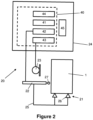
- FIG. 2 shows a schematic drawing of a test apparatus 20 that is suitable for performing the test on the substrate monolith 1.
- the test apparatus 20 comprises a support system 21 for isolating the substrate monolith 1 from extraneous vibrations, the impact tool 22, a transducer 23 for sensing mechanical vibrations of the substrate monolith 1, and an analyser 24 for determining the fundamental frequency of the sensed mechanical vibrations.
- the support system 21 and the impact tool 22 may both be coupled to an alignment frame 25 configured to ensure that the impulse vector 30 of the impulse J applied by the impact tool 22 to the substrate monolith 1 supported by the support system 21 has the non-zero first-axis component 31 and the non-zero second-axis component 32.
- the support system 21 may comprise one or more support members 26.
- Each support member 26 may comprise an elastomer, foam or rubber member.
- 3 or 4 support members 26 may be used that are positioned at one or more nodal points of the substrate monolith 1, preferably at one or more of the fundamental nodal points of the substrate monolith 1.
- the support members 26 may contact a base of the substrate monolith 1 at points around a nodal circle of the substrate monolith 1.
- the nodal circle may be a circle whose diameter is approximately 68% of the substrate monolith's mean diameter in the case of cylindrical substrate monoliths.
- 4 support members 26 may be used that are equi-spaced around the nodal circle, that is being angularly arranged with 90° separations there between.
- the impact tool 22 may comprise, for example, an automated hammer configured to apply the impulse J to the substrate monolith 1 with the impulse vector 30 having the non-zero first-axis component 31 and the non-zero second-axis component 32.
- the impact tool 22 may be configured to apply a pre-determined impulse to the substrate monolith 1.
- the impact tool 22 may preferably be computer-controlled. In some examples the impact tool 22 may be an automated hammer.
- the impact tool 22 may comprise a metal or wooden head 27 that contacts the substrate monolith 1 in use.
- the transducer 23 may comprise a contact or non-contact transducer.
- the transducer 23 may be an accelerometer that may be applied to a surface of the substrate monolith 1.
- the transducer 23 may be a microphone, optionally a unidirectional microphone, may be used to sense the mechanical vibrations by sensing the sound waves produced by the mechanical vibrations of the substrate monolith 1.
- the analyser 24 may comprise controller 40.
- the controller 40 may comprise one or more processors 41, an impact tool controller 42, a signal input 43 connected to the transducer 23, and a memory 44 for storage of, for example, software and data.
- the analyser 24 may further comprise an output, for example a display screen 45.
- the one or more processors 41 may comprise analysis programming for analysing the sensed mechanical vibrations and converting the sensed mechanical vibrations into a frequency domain to produce a frequency spectrum of the sensed mechanical vibrations.
- analysis programming may perform a Fast Fourier Transformation.
- the one or more processors 41 may further perform a Power Spectral Density (PSD) analysis on the frequency spectrum.
- PSD Power Spectral Density
- the one or more processors 41 may be provided in a single machine housing, or in a plurality of housings, and/or may be provided by distributed processing means, for example cloud-based processors.
- Figure 3 is an end view of a portion of the substrate monolith 1 illustrating one of the cells 12 defined in the X-Y plane by the first walls 10 (parallel to the X-axis) and the second walls 11 (parallel to the Y-axis).
- the stiffness of the substrate monolith 1 parallel to each of the first walls 10 and the second walls 11 is illustrated by the arrows k x and k y .
- k x k y
- the stiffness diagonally with respect to the first walls 10 and the second walls 11 (for example at 45°) of the square channels will be lower and is illustrated in Figure 3 by arrow k d .
- the impulse vector 30 of the impulse J has a non-zero first-axis component 31 and a non-zero second-axis component 32.
- the impulse vector 30 may have substantially equal first-axis and second-axis components 31, 32.
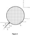
- Figure 4 where the impulse J is applied by striking the substrate monolith 1 in a diagonal direction with respect to the first-axis (the X-axis) and the second-axis (the Y-axis).
- the impulse J is applied by striking the substrate monolith 1 in a direction at 45° to the X-axis and the Y-axis.
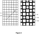
- Figure 5 illustrates the angle of the impulse vector 30 for two examples of substrate monolith 1.
- the cells 12 of the left-hand example of Figure 5 are uniform square-shaped cells.
- the cells 12 of the right-hand example of Figure 5 are of varying size and shape, in a pattern referred to as 'octo-square'.
- the first walls 10 and the second walls 11 define smaller, square-shaped cells 12a and larger cells 12b.
- the larger cells 12b may have truncated corners forming octagon-shaped cells.
- the angle of the impulse vector 30 may be considered to extend diagonally relative to the octagon-shaped cells 12b as shown by the arrow in Figure 5 , in the same way as for the square-shaped cells 12a.
- the second monolith may comprise, for example, a reference substrate monolith, or a substrate monolith from a different batch of substrate monoliths compared to the substrate monolith 1, or may be a substrate monolith from the same batch of substrate monoliths as the substrate monolith 1.
- a bare (uncoated) aluminium titanate filter substrate monolith having octo-square-shaped cells was used to study the effect of impact direction.
- the substrate monolith was impacted by the impact tool with two types of impact.
- the impulse vector was aligned parallel to the first-axis so that it was at 0° to the first-axis walls of the substrate monolith (the ⁇ Parallel direction').
- the impulse vector was aligned diagonally to the first-axis so that it was at 45° to the first-axis walls (and also the second-axis walls) of the substrate monolith (the 'Diagonal direction').
- Figure 6 illustrates the frequency spectrums obtained from both types of impact using the test apparatus.
- the mechanical vibrations sensed by the microphone were converted into the frequency domain to produce the frequency spectrum of the sensed mechanical vibrations.
- the frequency spectrum does not comprise any single clear strongest fundamental frequency.
- the Diagonal direction impacts produce a clearly discriminable fundamental frequency at around 1000 Hz that also has a greater amplitude compared to the Parallel direction impacts.
- Figure 7 illustrates another example frequency spectrum obtained from a flow-through substrate monolith using the test of the present disclosure.
- the flow-through substrate monolith was a cordierite substrate having square-shaped cells and was coated with a PGM/AL 2 O 3 catalyst.
- a single clearly discriminable fundamental frequency at around 1300 Hz was obtained using an impact angled at 45° to the first-axis walls.
- the second substrate monolith of the method may be used as a reference substrate monolith.
- the method may further comprise the step of making a judgement regarding a crack status of the substrate monolith based on the comparison of the fundamental frequencies obtained for the substrate monolith and the reference substrate monolith.
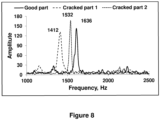
- Figure 8 illustrates results of three frequency spectrums obtained by the present method for three filter substrate monoliths.
- the filter substrate monoliths were aluminium titanate substrates having octo-square-shaped cells and being coated with CuO/zeolite - an un-cracked substrate monolith ( ⁇ Good part') acting as the reference substrate monolith, a first cracked substrate monolith ( ⁇ Crack ed part 1') and a second cracked substrate monolith ( ⁇ Cracked part 2').
- Cracked part 1 and Cracked part 2 comprised washcoated and calcined substrate monoliths that were heated in an oven to 600° C. The over door was then opened to allow cold air to pass over the hot surfaces of the substrate monoliths. Due to the resulting thermal shock, surface cracking of the substrate monoliths was observed with cracks extending from 3 cm to 16 cm along the Z-axis and penetrating 1 to 5 cm in the radial direction.
- the fundamental frequency obtained from the Good part was 1636 Hz, compared to 1412 Hz and 1532 Hz respectively from the Cracked part 1 and Cracked part 2.
- the change in fundamental frequency in this example a reduction may be used to judge whether the tested substrate monolith has been cracked.
- the method may be used to discern whether a substrate monolith has internal cracks.
- internal cracks may develop, for example, when a substrate monolith is subjected to high cooling rates following calcination.
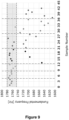
- Figure 9 illustrates the fundamental frequencies obtained from 42 samples of an SCRF filter substrate monolith.
- the filter substrate monoliths were aluminium titanate substrates having octo-square-shaped cells and being coated with CuO/zeolite.
- the samples were heated to a calcination temperature of 500°C and then subjected to cooling rates varying between 3 and 9°C/min, as follows: Sample No. Cooling rate (°C/min) 1 to 4 3 5 to 8 4 9 to 12 5 13 to 20 6 21 to 28 7 29 to 36 8 37 to 42 9
- the second substrate may, for example, be chosen to be one that has been subjected to a slow cooling rate of less than or equal to 3°C/min such that a 'reference' fundamental frequency of approximately 1770 Hz is obtained.
- the substrate monolith and the second substrate monolith may be from respective first and second batches of substrate monoliths.
- the method may further comprise the step of making a judgement regarding a variance between the batches of substrate monoliths based on the comparison of the fundamental frequencies obtained for the substrate monolith and the second substrate monolith.
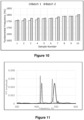
- FIG 10 illustrates fundamental frequencies obtained from two batches of ten flow-through substrate monoliths.
- Each flow-through substrate monolith was a cordierite substrate having square-shaped cells and was coated with a PGM/AL 2 O 3 catalyst.
- Both Batch 1 and Batch 2 had identical slurry compositions, washcoat loading, calcination temperature, etc. but were produced at different times. As can be seen from the results the fundamental frequencies appear generally consistent between batches. Further, statistical testing using a T test indicated that, for this example, the variance between the batches was not statistically significant.
- the method may be used to make judgements between substrate monoliths manufactured at different times.
- FIG 11 illustrates fundamental frequencies obtained from 4 different flow-through substrate monoliths that are comparable to each other in terms of their end use but are from 4 different manufacturers.
- Each substrate monolith was an uncoated cordierite substrate having square-shaped cells.
- the second substrate monolith may be a previously selected substrate monolith.
- the other substrate monoliths may be potential replacement substrate monoliths that are being compared against the previously selected substrate monolith.
- the previously selected substrate monolith produces a fundamental frequency of about 415 Hz. If the three potential replacements Option 1 has a similar fundamental frequency of about 425 Hz whereas Option 2 and Option 3 have fundamental frequencies of 485 and 492 Hz respectively.
- the method may be used to make judgements between substrate monoliths obtained from different sources.
- the substrate monolith and the second substrate monolith may be from a single batch of substrate monoliths having the same configuration.
- the method may further comprise the step of making a judgement regarding a variance within the single batch of substrate monoliths based on the comparison of the fundamental frequencies obtained for the substrate monolith and the second substrate monolith.
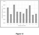
- FIG 12 a sample of 10 GPF filter substrate monoliths was tested.
- Each filter substrate monolith was an uncoated cordierite substrate having square-shaped cells.
- the fundamental frequencies obtained varied from about 2620 Hz to 2905 Hz.
- the comparison of the fundamental frequencies may comprise determining if there is a statistically significant variation in the fundamental frequencies obtained for the substrate monoliths of the single batch.
Landscapes
- Physics & Mathematics (AREA)
- Engineering & Computer Science (AREA)
- Chemical & Material Sciences (AREA)
- General Physics & Mathematics (AREA)
- Health & Medical Sciences (AREA)
- General Health & Medical Sciences (AREA)
- Biochemistry (AREA)
- Analytical Chemistry (AREA)
- Immunology (AREA)
- Life Sciences & Earth Sciences (AREA)
- Pathology (AREA)
- Acoustics & Sound (AREA)
- Signal Processing (AREA)
- General Engineering & Computer Science (AREA)
- Mechanical Engineering (AREA)
- Combustion & Propulsion (AREA)
- Chemical Kinetics & Catalysis (AREA)
- Spectroscopy & Molecular Physics (AREA)
- Mathematical Physics (AREA)
- Measurement Of Mechanical Vibrations Or Ultrasonic Waves (AREA)
- Exhaust Gas After Treatment (AREA)
- Investigating Or Analyzing Materials By The Use Of Ultrasonic Waves (AREA)
Abstract
i) a plurality of channels extending longitudinally along a Z-axis of the substrate monolith (1); and
ii) an array of walls extending along the Z-axis and forming partitions between adjacent channels;
wherein the array of walls comprises first walls (10) orientated parallel to a first-axis of the substrate monolith (1) and second walls (11) orientated parallel to a second-axis of the substrate monolith (1), the first-axis and the second-axis both being orthogonal to the Z-axis;
the method comprising the steps of:
a) applying an impulse (J) to the substrate monolith (1) with an impact tool (22) to induce mechanical vibrations in the substrate monolith (1);
b) sensing the mechanical vibrations of the substrate monolith (1);
c) determining a fundamental frequency of the sensed mechanical vibrations; and
d) comparing the fundamental frequency of the sensed mechanical vibrations to a fundamental frequency obtained from testing of a second substrate monolith;
wherein in step a) an impulse vector (30) of the impulse (J) has a non-zero first-axis component (31) and a non-zero second-axis component (32).
Description
- The present disclosure relates to a method of testing substrate monoliths and a test apparatus for performing the method.
- Substrate monoliths are used for the treatment of exhaust gases emitted from internal combustion engines, for example vehicular internal combustion engines. Substrate monoliths may treat the exhaust gases, for example, by filtering the exhaust gas to remove particulate matter and/or by using a catalyst to oxidise and/or reduce components of the exhaust gas such as carbon monoxide, unburned hydrocarbons and oxides of nitrogen.
- Substrate monoliths may typically be formed from sintered metal, ceramic or metal fibres etc. The substrate monoliths are fragile due for example to their material composition and/or for example due to the presence of thin-walled structures that define the channels for gas flow within the substrate monolith. Substrate monoliths may therefore be prone to cracking when subjected to mechanical and/or thermal shocks. The manufacture of substrate monoliths necessarily involves mechanical manipulation of the substrate monoliths on a production line which may lead to imposition of mechanical loads on the substrate monolith, e.g. from accidents or when being transferred from one part of the production line to another. The manufacturing process also involves the application of thermal changes, e.g. when baking and cooling the bare substrate monolith and during calcination of the substrate monolith after application of a washcoat. Consequently, it would be desirable to test the substrate monoliths for the presence of cracks and/or other defects during or after manufacture before the substrate monoliths are despatched to a customer.
- A problem with testing of substrate monoliths is that the cracks or other defects may be difficult to discern visually. External cracks (i.e. cracks propagating to/from an external surface of the substrate monolith) may be narrow, may be closed at rest, and/or may be difficult to discern under the lighting conditions typically present on a production line. Internal cracks within the body of the substrate monolith cannot easily be inspected visually, in particular by a human operator on a production line. Visual inspection in general is also time-consuming and therefore in practice can only be applied to a small sample percentage of the substrate monoliths that are produced.
- It has been known for some human operators to tap a substrate monolith with their fingers to attempt to discern the presence of defects by listening for a `dull' response. However, this technique requires a level of experience of the human operator and in addition the perception of sound varies from person to person. Thus, the conclusions from such `tap' tests are very challenging to interpret and difficult to report to customers in an informative manner. Further, as with visual inspection, the method is time consuming and can only be applied to a small sample percentage of the substrate monoliths that are produced.
- In a first aspect the present disclosure provides a method of testing a substrate monolith, the substrate monolith comprising:
- i) a plurality of channels extending longitudinally along a Z-axis of the substrate monolith; and
- ii) an array of walls extending along the Z-axis and forming partitions between adjacent channels;
- wherein the array of walls comprises first walls orientated parallel to a first-axis of the substrate monolith and second walls orientated parallel to a second-axis of the substrate monolith, the first-axis and the second-axis both being orthogonal to the Z-axis;
- the method comprising the steps of:
- a) applying an impulse to the substrate monolith with an impact tool to induce mechanical vibrations in the substrate monolith;
- b) sensing the mechanical vibrations of the substrate monolith;
- c) determining a fundamental frequency of the sensed mechanical vibrations; and
- d) comparing the fundamental frequency of the sensed mechanical vibrations to a fundamental frequency obtained from testing of a second substrate monolith;
- wherein in step a) an impulse vector of the impulse has a non-zero first-axis component and a non-zero second-axis component.
- Advantageously, the fundamental frequencies obtained from the substrate monolith being tested and the second substrate monolith are used for the comparison. Using the fundamental frequencies may reduce or eliminate destructive interference from other frequencies.
- The method may also be carried out very quickly, for example in under 5 seconds per substrate monolith. Advantageously, the method does not rely on human operator perception and is suitable for use on a production line. In particular, it has been surprisingly found that the method can be carried out despite the presence of relatively large amounts of background noise, as typically present in a factory production line setting.
- Advantageously, the impulse vector of the impulse has a non-zero first-axis component and a non-zero second-axis component. Consequently, the impulse vector is not directly aligned with either the first walls or the second walls of the substrate monolith. This angling of the impulse vector has been found to produce a lower fundamental frequency in the sensed mechanical vibrations compared to an impulse vector applied that is aligned with the first walls or the second walls of the substrate monolith. In addition, the angling of the impulse vector has been found to produce a stronger signal amplitude for the fundamental frequency when used with substrate monoliths that is more easily discriminable from other resonances and background noise (including for example background noise from a factory setting).
- In addition, a further advantage is that the stronger resonant response of the substrate monolith when the impulse vector is not directly aligned with either the first walls or the second walls means that the magnitude of the impulse can be reduced. This reduces the chance that the impact tool will damage the substrate monolith when applying the impulse.
- Without wishing to be bound by theory, it is believed that the stronger and more discriminable resonant response of the substrate monolith when the impulse vector is not directly aligned with either the first walls or the second walls is due to the in-plane anisotropy of the substrate monolith. The first walls and second walls of the substrate monolith produce a 'honeycomb' network of cells in the plane that is orthogonal to the Z-axis. Typically in a substrate monolith the thickness of the first walls and the second walls (the cell walls) is smaller than the width of the cell opening. Taking the example of square-shaped cells, the plane of the substrate monolith orthogonal to the Z-axis may resemble a checkerboard pattern having a 2-D array of hollow square cells having centres aligned parallel to the first- and second-axes. This plane is anisotropic for stiffness - it has a different stiffness dependent on the direction of the applied force. In particular, in the example of square cells (assuming constant wall thickness for all walls) the stiffness parallel to each of the first walls and the second walls will be the same. However, the stiffness at 45° to the first and second walls of the square channels will be lower.
- In preferred examples, in step a) the impulse vector has substantially equal first-axis and second-axis components. This may be particularly appropriate, for example, where the channel has substantially the same length dimension in each of the first-axis and the second-axis. One example would be square cells. Where the channels have other shapes the angling of the impulse vector may require adjustment. For example, where the channels are rectangular-shaped (non-square) or rhomboid-shaped the impulse vector may, for example, be angled to be parallel to a longest in-plane diagonal dimension of the channel.
- In some examples, in step a) the impulse is applied by striking the substrate monolith in a diagonal direction with respect to the first-axis and the second-axis. In some examples, the first-axis and the second-axis are orthogonal to one another, being an X-axis and a Y-axis respectively of the substrate monolith. In such examples, in step a) the impulse may be applied by striking the substrate monolith in a direction at 45° to the X-axis and the Y-axis.
- In some examples the plurality of channels comprise quadrilateral-shaped channels, optionally square-shaped channels.
- In some examples the substrate monolith is supported on a support system to isolate the substrate monolith from extraneous vibrations.
- In some examples the support system comprises a single support member. In some other examples the support system comprises a plurality of support members. In such examples the support members may
number - In some examples the substrate monolith may be supported at one or more nodal points of the substrate monolith, preferably at one or more of the fundamental nodal points of the substrate monolith.
- In some examples, in step b) sensing the mechanical vibrations of the substrate monolith comprises using a transducer to sense the mechanical vibrations in a time domain. In some examples the transducer may comprise a contact accelerometer that may be applied to a surface of the substrate monolith. However, in other preferred examples, a non-contact transducer may be used. For example, a microphone, optionally a unidirectional microphone, may be used to sense the mechanical vibrations by sensing the sound waves produced by the mechanical vibrations of the substrate monolith.
- In some examples, in step c) determining the fundamental frequency comprises converting the sensed mechanical vibrations into a frequency domain to produce a frequency spectrum of the sensed mechanical vibrations. In such examples, in step c) determining the fundamental frequency may further comprise applying a Power Spectral Density (PSD) analysis to the frequency spectrum.
- Advantageously, converting the sensed mechanical vibrations into the frequency domain can produce more reliable results for a wider range of substrate monoliths compared to a time domain analysis. For example, many substrate monoliths are highly porous and/or formed from ceramics that may contain many microcracks. This can lead to such substrate monoliths not producing a pure tone when impacted. As a result a time-domain analysis of the mechanical vibrations has been found to be difficult. According to the present method by converting into the frequency domain, this difficulty may be overcome.
- The conversion into the frequency domain may, for example, be by use of a Fast Fourier Transformation algorithm. The use of a PSD analysis may advantageously reduce or eliminate ambiguity in determining the fundamental frequency from the frequency spectrum.
- In some examples, the impact tool may be configured to apply a pre-determined impulse. The impact tool may be automated. For example, the impact tool may be computer-controller to improve the accuracy and reproducibility of the impulse, in particular in terms of its magnitude. In some examples the impact tool may be an automated hammer. In some examples the impact tool may comprise a metal or wooden head that contacts the substrate monolith in use. A wooden head may be preferable where the substrate monolith is particularly fragile. A metal head may be preferable where it is desired to obtain a greater signal intensity from the impact. As an example of a metal head, a stainless steel head can be used. Also, an alumina material has been found to be particularly effective for the head. It has been found that the material of the head does not change the fundamental frequency obtained but, as noted above, can affect the signal intensity.
- The second monolith may comprise, for example, a reference substrate monolith, or a substrate monolith from a different batch of substrate monoliths compared to the substrate monolith, or may be a substrate monolith from the same batch of substrate monoliths as the substrate monolith.
- For example, the second substrate monolith may be a reference substrate monolith and the method further may comprise the step of making a judgement regarding a crack status of the substrate monolith based on the comparison of the fundamental frequencies obtained for the substrate monolith and the reference substrate monolith.
- Advantageously, the reference substrate monolith may be a substrate monolith that is known to be un-cracked, for example free of any substantial defect.
- The comparison of the fundamental frequencies may comprise determining if there is a difference in the fundamental frequencies. Optionally, it may comprise determining if the difference exceeds a threshold amount. The threshold amount may be an absolute amount (e.g. a number of Hertz) or may be a relative amount (e.g. a percentage deviation in the frequency obtained for the substrate monolith compared to the reference substrate monolith).
- The comparison of the fundamental frequencies may comprise determining a direction of shift of the fundamental frequency, e.g. whether the fundamental frequency obtained for the substrate monolith is greater than or less than that obtained for the reference substrate monolith.
- For example, the substrate monolith and the second substrate monolith may be from respective first and second batches of substrate monoliths and the method may further comprise the step of making a judgement regarding a variance between the batches of substrate monoliths based on the comparison of the fundamental frequencies obtained for the substrate monolith and the second substrate monolith.
- In making the determination, the fundamental frequencies obtained from one or more substrate monoliths from the first batch may be compared with the fundamental frequencies obtained from one or more substrate monoliths from the second batch. For example, each batch that is tested may comprise 3 or more, 5 or more, or 10 or more substrate monoliths that are tested.
- The comparison of the fundamental frequencies may comprise determining if there is a statistically significant difference in the fundamental frequencies obtained for the substrate monoliths of the first batch and those of the second batch.
- For example, the substrate monolith and second substrate monolith may be from a single batch of substrate monoliths and the method may further comprise the step of making a judgement regarding a variance within the single batch of substrate monoliths based on the comparison of the fundamental frequencies obtained for the substrate monolith and the second substrate monolith.
- In making the determination, the fundamental frequencies obtained from 3 or more, 5 or more, or 10 or more substrate monoliths of the single batch may be used.
- The comparison of the fundamental frequencies may comprise determining if there is a statistically significant variation in the fundamental frequencies obtained for the substrate monoliths of the single batch.
- In some examples, the method is performed on a production line configured to process a plurality of substrate monoliths.
- The substrate monolith may be formed for example from sintered metal, ceramic or metal fibres etc. For example, the substrate monolith may be formed from cordierite, various forms of silicon carbide or aluminium titanate.
- The substrate monolith may be a "bare" substrate monolith or alternatively may comprise a composition (known as a washcoat) that coats the porous structure of the substrate monolith. The washcoat may be a catalytic washcoat to produce a catalysed substrate monolith having a catalytic function ability, for example oxidation, NOx-trapping, or selective catalytic reduction activity. The catalytic washcoat may comprise a catalyst, selected from the group consisting of a hydrocarbon trap, a three-way catalyst (TWC), a NOx absorber, an oxidation catalyst, e.g. a diesel oxidation catalyst (DOC), a selective catalytic reduction (SCR) catalyst, a lean NOx catalyst and combinations of any two or more thereof. The catalyst, for example the TWC, NOx absorber, oxidation catalyst, hydrocarbon trap and the lean NOx catalyst, may contain one or more platinum group metals, particularly those selected from the group consisting of platinum, palladium and rhodium.
- In some examples the substrate monolith being tested may be a calcined substrate monolith. In such examples the substrate monolith and the reference substrate monolith have preferably been subjected to substantially the same calcination conditions.
- The substrate monolith may comprise either a flow-through substrate monolith or a filter substrate monolith. In a flow-through substrate monolith a plurality of channels (also referred to as `cells') extend longitudinally along the length (Z-axis) of the substrate monolith wherein the channels are open at both ends thereof. In a filter substrate monolith (also referred to as a `wall-flow filter substrate monolith') a plurality of channels ('cells') extend longitudinally along the length (Z-axis) of the substrate monolith wherein channels at a first end of the substrate monolith that are open are blocked at the opposite end and channels that are open at the opposite end are blocked at the first end, the arrangement being such that every other adjacent channel has an open end (or a blocked end) on the first end of the filter substrate monolith and a blocked end (or an open end) on the opposite end thereof so that when an end of the filter substrate monolith is viewed it resembles a chess board of open and blocked channels. Fluid communication between the open channels at the first end of the filter substrate monolith and the open channels of the opposite end thereof is via the porous wall structure of the filter substrate monolith.
- The external shape and dimensions of the substrate monolith, as well as properties such as the channel wall thickness and its porosity etc. may be varied depending on the intended application for the substrate monolith. The substrate monolith may be configured for use with an internal combustion engine (ICE) to filter an exhaust gas emitted by the internal combustion engine. The internal combustion engine may be a spark ignition engine, e.g. a gasoline ICE, or a compression ignition engine, e.g., a diesel ICE.
- In a second aspect the present disclosure provides a test apparatus for performing the method of the first aspect, comprising:
- a support system for isolating the substrate monolith from extraneous vibrations;
- an impact tool;
- a transducer for sensing mechanical vibrations of the substrate monolith; and
- an analyser for determining the fundamental frequency of the sensed mechanical vibrations;
- wherein the impact tool comprises an automated hammer configured to apply the impulse to the substrate monolith with an impulse vector having a non-zero first-axis component and a non-zero second-axis component.
- In some examples, the support system and the impact tool are both coupled to an alignment frame configured to ensure that the impulse vector of the impulse applied by the impact tool to the substrate monolith supported by the support system has the non-zero first-axis component and the non-zero second-axis component.
- Aspects and embodiments of the present disclosure will now be described, by way of example only, with reference to the accompanying drawings, in which:
-
Figure 1 is a schematic view of a substrate monolith; -
Figure 2 is a schematic drawing of a test apparatus; -
Figure 3 is an end view of a portion of a substrate monolith; -
Figure 4 is a schematic end view of a substrate monolith being subjected to an impulse; -
Figure 5 shows end views of portions of two substrate monoliths; -
Figure 6 is a graph of frequency vs. amplitude illustrating the effect of impulse direction; -
Figure 7 is a graph of frequency vs. amplitude illustrating an example test result; -
Figure 8 is a graph of frequency vs. amplitude illustrating example test results for cracked and un-cracked substrate monoliths; -
Figure 9 is a plot of fundamental frequencies obtained for 42 samples of substrate monolith; -
Figure 10 is a plot of fundamental frequencies obtained for two batches, each containing 10 samples of substrate monolith; -
Figure 11 is graph of frequency vs. amplitude illustrating example test results for substrate monoliths from four different sources; and -
Figure 12 is a plot of fundamental frequencies obtained for 10 samples of substrate monolith from a single batch. - The skilled reader will recognise that one or more features of one aspect or embodiment of the present disclosure may be combined with one or more features of any other aspect or embodiment of the present disclosure unless the immediate context teaches otherwise.
-
Figure 1 is a schematic view of asubstrate monolith 1. Thesubstrate monolith 1 comprises a plurality of channels extending longitudinally along a Z-axis of thesubstrate monolith 1 and an array ofwalls - The array of walls comprises
first walls 10 orientated parallel to a first-axis of thesubstrate monolith 1 andsecond walls 11 orientated parallel to a second-axis of thesubstrate monolith 1, the first-axis and the second-axis both being orthogonal to the Z-axis. The first-axis and the second-axis may be orthogonal to one another. The first-axis may be an X-axis and the second-axis may be a Y-axis respectively of thesubstrate monolith 1. - The
first walls 10 and the second walls may 11 define 'cells' 12 when viewed in the X-Y plane of thesubstrate monolith 1. In the illustrated example thecells 12 are square-shaped. However, thecells 12 may take other shapes. Thesubstrate monolith 1 may have a cylindrical external shape, although other shapes can be provided. - According to the present disclosure the method of testing the
substrate monolith 1 comprises the steps of: - a) applying an impulse J to the
substrate monolith 1 with animpact tool 22 to induce mechanical vibrations in thesubstrate monolith 1; - b) sensing the mechanical vibrations of the
substrate monolith 1; - c) determining a fundamental frequency of the sensed mechanical vibrations; and
- d) comparing the fundamental frequency of the sensed mechanical vibrations to a fundamental frequency obtained from testing of a second substrate monolith;
-
Figure 2 shows a schematic drawing of atest apparatus 20 that is suitable for performing the test on thesubstrate monolith 1. Thetest apparatus 20 comprises asupport system 21 for isolating thesubstrate monolith 1 from extraneous vibrations, theimpact tool 22, atransducer 23 for sensing mechanical vibrations of thesubstrate monolith 1, and ananalyser 24 for determining the fundamental frequency of the sensed mechanical vibrations. - The
support system 21 and theimpact tool 22 may both be coupled to analignment frame 25 configured to ensure that theimpulse vector 30 of the impulse J applied by theimpact tool 22 to thesubstrate monolith 1 supported by thesupport system 21 has the non-zero first-axis component 31 and the non-zero second-axis component 32. - The
support system 21 may comprise one ormore support members 26. Eachsupport member 26 may comprise an elastomer, foam or rubber member. In some preferred examples 3 or 4support members 26 may be used that are positioned at one or more nodal points of thesubstrate monolith 1, preferably at one or more of the fundamental nodal points of thesubstrate monolith 1. For example, thesupport members 26 may contact a base of thesubstrate monolith 1 at points around a nodal circle of thesubstrate monolith 1. The nodal circle may be a circle whose diameter is approximately 68% of the substrate monolith's mean diameter in the case of cylindrical substrate monoliths. In some particularly preferred examples, 4support members 26 may be used that are equi-spaced around the nodal circle, that is being angularly arranged with 90° separations there between. - The
impact tool 22 may comprise, for example, an automated hammer configured to apply the impulse J to thesubstrate monolith 1 with theimpulse vector 30 having the non-zero first-axis component 31 and the non-zero second-axis component 32. Theimpact tool 22 may be configured to apply a pre-determined impulse to thesubstrate monolith 1. Theimpact tool 22 may preferably be computer-controlled. In some examples theimpact tool 22 may be an automated hammer. Theimpact tool 22 may comprise a metal orwooden head 27 that contacts thesubstrate monolith 1 in use. - The
transducer 23 may comprise a contact or non-contact transducer. For example thetransducer 23 may be an accelerometer that may be applied to a surface of thesubstrate monolith 1. In preferred examples, thetransducer 23 may be a microphone, optionally a unidirectional microphone, may be used to sense the mechanical vibrations by sensing the sound waves produced by the mechanical vibrations of thesubstrate monolith 1. - The
analyser 24 may comprisecontroller 40. Thecontroller 40 may comprise one ormore processors 41, animpact tool controller 42, asignal input 43 connected to thetransducer 23, and amemory 44 for storage of, for example, software and data. Optionally theanalyser 24 may further comprise an output, for example adisplay screen 45. - The one or
more processors 41 may comprise analysis programming for analysing the sensed mechanical vibrations and converting the sensed mechanical vibrations into a frequency domain to produce a frequency spectrum of the sensed mechanical vibrations. For example the analysis programming may perform a Fast Fourier Transformation. The one ormore processors 41 may further perform a Power Spectral Density (PSD) analysis on the frequency spectrum. - The one or
more processors 41 may be provided in a single machine housing, or in a plurality of housings, and/or may be provided by distributed processing means, for example cloud-based processors. -
Figure 3 is an end view of a portion of thesubstrate monolith 1 illustrating one of thecells 12 defined in the X-Y plane by the first walls 10 (parallel to the X-axis) and the second walls 11 (parallel to the Y-axis). The stiffness of thesubstrate monolith 1 parallel to each of thefirst walls 10 and thesecond walls 11 is illustrated by the arrows kx and ky. For a square-celled substrate monolith 1 typically kx = ky. However, the stiffness diagonally with respect to thefirst walls 10 and the second walls 11 (for example at 45°) of the square channels will be lower and is illustrated inFigure 3 by arrow kd. - As noted above, the
impulse vector 30 of the impulse J has a non-zero first-axis component 31 and a non-zero second-axis component 32. In preferred examples, theimpulse vector 30 may have substantially equal first-axis and second-axis components Figure 4 where the impulse J is applied by striking thesubstrate monolith 1 in a diagonal direction with respect to the first-axis (the X-axis) and the second-axis (the Y-axis). In the illustrated example the impulse J is applied by striking thesubstrate monolith 1 in a direction at 45° to the X-axis and the Y-axis. -
Figure 5 illustrates the angle of theimpulse vector 30 for two examples ofsubstrate monolith 1. Thecells 12 of the left-hand example ofFigure 5 are uniform square-shaped cells. Thecells 12 of the right-hand example ofFigure 5 are of varying size and shape, in a pattern referred to as 'octo-square'. In particular, thefirst walls 10 and thesecond walls 11 define smaller, square-shapedcells 12a andlarger cells 12b. Thelarger cells 12b may have truncated corners forming octagon-shaped cells. However, for the purposes of the present disclosure it will be noted that in the case of the octagon-shapedcells 12b the sides of thecell 12b with the longest dimensions are those aligned parallel to the first-axis and the second-axis. Thus, the angle of theimpulse vector 30 may be considered to extend diagonally relative to the octagon-shapedcells 12b as shown by the arrow inFigure 5 , in the same way as for the square-shapedcells 12a. - The second monolith may comprise, for example, a reference substrate monolith, or a substrate monolith from a different batch of substrate monoliths compared to the
substrate monolith 1, or may be a substrate monolith from the same batch of substrate monoliths as thesubstrate monolith 1. - In the following examples substrate monoliths were tested using the method and testing apparatus as described above.
- A bare (uncoated) aluminium titanate filter substrate monolith having octo-square-shaped cells was used to study the effect of impact direction. The substrate monolith was impacted by the impact tool with two types of impact. In a first type of impact the impulse vector was aligned parallel to the first-axis so that it was at 0° to the first-axis walls of the substrate monolith (the `Parallel direction'). In a second type of impact the impulse vector was aligned diagonally to the first-axis so that it was at 45° to the first-axis walls (and also the second-axis walls) of the substrate monolith (the 'Diagonal direction').
-
Figure 6 illustrates the frequency spectrums obtained from both types of impact using the test apparatus. In particular, during the test the mechanical vibrations sensed by the microphone were converted into the frequency domain to produce the frequency spectrum of the sensed mechanical vibrations. As can be seen, for the Parallel direction impacts the frequency spectrum does not comprise any single clear strongest fundamental frequency. By contrast, the Diagonal direction impacts produce a clearly discriminable fundamental frequency at around 1000 Hz that also has a greater amplitude compared to the Parallel direction impacts. -
Figure 7 illustrates another example frequency spectrum obtained from a flow-through substrate monolith using the test of the present disclosure. The flow-through substrate monolith was a cordierite substrate having square-shaped cells and was coated with a PGM/AL2O3 catalyst. In this example a single clearly discriminable fundamental frequency at around 1300 Hz was obtained using an impact angled at 45° to the first-axis walls. - The second substrate monolith of the method may be used as a reference substrate monolith. The method may further comprise the step of making a judgement regarding a crack status of the substrate monolith based on the comparison of the fundamental frequencies obtained for the substrate monolith and the reference substrate monolith.
-
Figure 8 illustrates results of three frequency spectrums obtained by the present method for three filter substrate monoliths. The filter substrate monoliths were aluminium titanate substrates having octo-square-shaped cells and being coated with CuO/zeolite - an un-cracked substrate monolith (`Good part') acting as the reference substrate monolith, a first cracked substrate monolith (`Crack ed part 1') and a second cracked substrate monolith (`Cracked part 2'). Crackedpart 1 andCracked part 2 comprised washcoated and calcined substrate monoliths that were heated in an oven to 600° C. The over door was then opened to allow cold air to pass over the hot surfaces of the substrate monoliths. Due to the resulting thermal shock, surface cracking of the substrate monoliths was observed with cracks extending from 3 cm to 16 cm along the Z-axis and penetrating 1 to 5 cm in the radial direction. - As can be seen, the fundamental frequency obtained from the Good part (the reference substrate monolith) was 1636 Hz, compared to 1412 Hz and 1532 Hz respectively from the
Cracked part 1 andCracked part 2. The change in fundamental frequency (in this example a reduction) may be used to judge whether the tested substrate monolith has been cracked. - As well as external cracks, the method may be used to discern whether a substrate monolith has internal cracks. Such internal cracks may develop, for example, when a substrate monolith is subjected to high cooling rates following calcination.
-
Figure 9 illustrates the fundamental frequencies obtained from 42 samples of an SCRF filter substrate monolith. The filter substrate monoliths were aluminium titanate substrates having octo-square-shaped cells and being coated with CuO/zeolite. The samples were heated to a calcination temperature of 500°C and then subjected to cooling rates varying between 3 and 9°C/min, as follows:Sample No. Cooling rate (°C/min) 1 to 4 3 5 to 8 4 9 to 12 5 13 to 20 6 21 to 28 7 29 to 36 8 37 to 42 9 - There were no visible external cracks observable on any of the sample after cooling. However, testing according to the present disclosure was able to discern that cooling rates of greater than 5°C/min resulted in internal cracking - recognisable from the decrease in fundamental frequency obtained. As can be seen, at 6°C/min some samples suffered internal cracking. A clear trend of increasing occurrence of internal cracking with increasing cooling rate was observed until at a cooling rate of 9°C/min all samples tested had suffered internal cracking.
- In this example the second substrate (reference substrate) may, for example, be chosen to be one that has been subjected to a slow cooling rate of less than or equal to 3°C/min such that a 'reference' fundamental frequency of approximately 1770 Hz is obtained.
- The substrate monolith and the second substrate monolith may be from respective first and second batches of substrate monoliths. The method may further comprise the step of making a judgement regarding a variance between the batches of substrate monoliths based on the comparison of the fundamental frequencies obtained for the substrate monolith and the second substrate monolith.
-
Figure 10 illustrates fundamental frequencies obtained from two batches of ten flow-through substrate monoliths. Each flow-through substrate monolith was a cordierite substrate having square-shaped cells and was coated with a PGM/AL2O3 catalyst. BothBatch 1 andBatch 2 had identical slurry compositions, washcoat loading, calcination temperature, etc. but were produced at different times. As can be seen from the results the fundamental frequencies appear generally consistent between batches. Further, statistical testing using a T test indicated that, for this example, the variance between the batches was not statistically significant. - Thus, the method may be used to make judgements between substrate monoliths manufactured at different times.
-
Figure 11 illustrates fundamental frequencies obtained from 4 different flow-through substrate monoliths that are comparable to each other in terms of their end use but are from 4 different manufacturers. Each substrate monolith was an uncoated cordierite substrate having square-shaped cells. In this case the second substrate monolith may be a previously selected substrate monolith. The other substrate monoliths may be potential replacement substrate monoliths that are being compared against the previously selected substrate monolith. As can be seen, in this example the previously selected substrate monolith produces a fundamental frequency of about 415 Hz. If the threepotential replacements Option 1 has a similar fundamental frequency of about 425 Hz whereasOption 2 andOption 3 have fundamental frequencies of 485 and 492 Hz respectively. - Thus, the method may be used to make judgements between substrate monoliths obtained from different sources.
- The substrate monolith and the second substrate monolith may be from a single batch of substrate monoliths having the same configuration. The method may further comprise the step of making a judgement regarding a variance within the single batch of substrate monoliths based on the comparison of the fundamental frequencies obtained for the substrate monolith and the second substrate monolith.
- In
Figure 12 a sample of 10 GPF filter substrate monoliths was tested. Each filter substrate monolith was an uncoated cordierite substrate having square-shaped cells. As can be seen the fundamental frequencies obtained varied from about 2620 Hz to 2905 Hz. - The comparison of the fundamental frequencies may comprise determining if there is a statistically significant variation in the fundamental frequencies obtained for the substrate monoliths of the single batch.
Claims (15)
- A method of testing a substrate monolith, the substrate monolith comprising:i) a plurality of channels extending longitudinally along a Z-axis of the substrate monolith; andii) an array of walls extending along the Z-axis and forming partitions between adjacent channels;wherein the array of walls comprises first walls orientated parallel to a first-axis of the substrate monolith and second walls orientated parallel to a second-axis of the substrate monolith, the first-axis and the second-axis both being orthogonal to the Z-axis;the method comprising the steps of:a) applying an impulse to the substrate monolith with an impact tool to induce mechanical vibrations in the substrate monolith;b) sensing the mechanical vibrations of the substrate monolith;c) determining a fundamental frequency of the sensed mechanical vibrations; andd) comparing the fundamental frequency of the sensed mechanical vibrations to a fundamental frequency obtained from testing of a second substrate monolith;wherein in step a) an impulse vector of the impulse has a non-zero first-axis component and a non-zero second-axis component.
- The method of claim 1, wherein in step a) the impulse vector has substantially equal first-axis and second-axis components.
- The method of claim 1 or claim 2, wherein in step a) the impulse is applied by striking the substrate monolith in a diagonal direction with respect to the first-axis and the second-axis.
- The method of any preceding claim, wherein the first-axis and the second-axis are orthogonal to one another, being an X-axis and a Y-axis respectively of the substrate monolith.
- The method of claim 4, wherein in step a) the impulse is applied by striking the substrate monolith in a direction at 45° to the X-axis and the Y-axis.
- The method of any preceding claim, wherein the plurality of channels comprise quadrilateral-shaped channels, optionally square-shaped channels.
- The method of any preceding claim, wherein the substrate monolith is supported on a support system to isolate the substrate monolith from extraneous vibrations.
- The method of any preceding claim, wherein in step b) sensing the mechanical vibrations of the substrate monolith comprises using a transducer to sense the mechanical vibrations in a time domain.
- The method of any preceding claim, wherein in step c) determining the fundamental frequency comprises converting the sensed mechanical vibrations into a frequency domain to produce a frequency spectrum of the sensed mechanical vibrations.
- The method of claim 9, wherein in step c) determining the fundamental frequency comprises applying a Power Spectral Density (PSD) analysis to the frequency spectrum.
- The method of any preceding claim, wherein the second substrate monolith is a reference substrate monolith and the method further comprises the step of making a judgement regarding a crack status of the substrate monolith based on the comparison of the fundamental frequencies obtained for the substrate monolith and the reference substrate monolith.
- The method of any one of claims 1 to 10, wherein the substrate monolith and the second substrate monolith are from respective first and second batches of substrate monoliths and the method further comprises the step of making a judgement regarding a variance between the batches of substrate monoliths based on the comparison of the fundamental frequencies obtained for the substrate monolith and the second substrate monolith.
- The method of any preceding claim, wherein the substrate monolith comprises a flow-through substrate monolith or a filter substrate monolith.
- A test apparatus for performing the method of any preceding claim, comprising:a support system for isolating the substrate monolith from extraneous vibrations;an impact tool;a transducer for sensing mechanical vibrations of the substrate monolith; andan analyser for determining the fundamental frequency of the sensed mechanical vibrations;wherein the impact tool comprises an automated hammer configured to apply the impulse to the substrate monolith with an impulse vector having a non-zero first-axis component and a non-zero second-axis component.
- The test apparatus of claim 15, wherein the support system and the impact tool are both coupled to an alignment frame configured to ensure that the impulse vector of the impulse applied by the impact tool to the substrate monolith supported by the support system has the non-zero first-axis component and the non-zero second-axis component.
Applications Claiming Priority (1)
| Application Number | Priority Date | Filing Date | Title |
|---|---|---|---|
| US202263369815P | 2022-07-29 | 2022-07-29 |
Publications (1)
| Publication Number | Publication Date |
|---|---|
| EP4312014A1 true EP4312014A1 (en) | 2024-01-31 |
Family
ID=87378000
Family Applications (1)
| Application Number | Title | Priority Date | Filing Date |
|---|---|---|---|
| EP23185795.4A Pending EP4312014A1 (en) | 2022-07-29 | 2023-07-17 | Testing of substrate monoliths |
Country Status (7)
| Country | Link |
|---|---|
| US (1) | US12546748B2 (en) |
| EP (1) | EP4312014A1 (en) |
| JP (1) | JP2025528612A (en) |
| KR (1) | KR20250016241A (en) |
| CN (1) | CN119487375A (en) |
| GB (1) | GB2622307B (en) |
| WO (1) | WO2024023486A1 (en) |
Citations (2)
| Publication number | Priority date | Publication date | Assignee | Title |
|---|---|---|---|---|
| JP2006334459A (en) * | 2005-05-31 | 2006-12-14 | Hitachi Metals Ltd | Ceramic honeycomb filter |
| US20070022724A1 (en) * | 2005-07-29 | 2007-02-01 | Gargano Patrick M | Method, system and apparatus for detecting defects in a honeycomb body using a particulate fluid |
Family Cites Families (6)
| Publication number | Priority date | Publication date | Assignee | Title |
|---|---|---|---|---|
| DE3943133A1 (en) * | 1989-12-28 | 1991-07-18 | Zeuna Staerker Kg | METHOD FOR ACOUSTICALLY TESTING MONOLITHS FOR DAMAGE AND DEVICE FOR IMPLEMENTING THE METHOD |
| JP2006250660A (en) * | 2005-03-10 | 2006-09-21 | Asahi Glass Co Ltd | Inspection method and inspection apparatus for ceramic honeycomb filter |
| US10607817B2 (en) | 2016-11-18 | 2020-03-31 | Applied Materials, Inc. | Thermal repeatability and in-situ showerhead temperature monitoring |
| RU2646607C1 (en) | 2017-03-28 | 2018-03-06 | Акционерное общество "НИИЭФА им. Д.В. Ефремова" (АО "НИИЭФА") | Method and mobile device for disposing methane from non-controlled sources |
| EP3417936A1 (en) | 2017-06-20 | 2018-12-26 | Zelp Ltd | Gas processing device |
| US11433352B1 (en) | 2021-10-18 | 2022-09-06 | Edan Prabhu | Apparatus and method for oxidizing fluid mixtures using porous and non-porous heat exchangers |
-
2023
- 2023-07-17 EP EP23185795.4A patent/EP4312014A1/en active Pending
- 2023-07-17 JP JP2024573689A patent/JP2025528612A/en active Pending
- 2023-07-17 WO PCT/GB2023/051866 patent/WO2024023486A1/en not_active Ceased
- 2023-07-17 KR KR1020247042469A patent/KR20250016241A/en active Pending
- 2023-07-17 CN CN202380049135.4A patent/CN119487375A/en active Pending
- 2023-07-17 GB GB2310913.5A patent/GB2622307B/en active Active
- 2023-07-19 US US18/354,665 patent/US12546748B2/en active Active
Patent Citations (2)
| Publication number | Priority date | Publication date | Assignee | Title |
|---|---|---|---|---|
| JP2006334459A (en) * | 2005-05-31 | 2006-12-14 | Hitachi Metals Ltd | Ceramic honeycomb filter |
| US20070022724A1 (en) * | 2005-07-29 | 2007-02-01 | Gargano Patrick M | Method, system and apparatus for detecting defects in a honeycomb body using a particulate fluid |
Also Published As
| Publication number | Publication date |
|---|---|
| JP2025528612A (en) | 2025-08-29 |
| GB2622307B (en) | 2025-02-12 |
| CN119487375A (en) | 2025-02-18 |
| US20240036007A1 (en) | 2024-02-01 |
| WO2024023486A1 (en) | 2024-02-01 |
| KR20250016241A (en) | 2025-02-03 |
| GB202310913D0 (en) | 2023-08-30 |
| GB2622307A (en) | 2024-03-13 |
| US12546748B2 (en) | 2026-02-10 |
Similar Documents
| Publication | Publication Date | Title |
|---|---|---|
| CN102980945B (en) | Frequency mixing nonlinear ultrasonic detection method for structure microcracks based on bispectrum analysis | |
| US7614304B2 (en) | Ultrasonic testing system and method for ceramic honeycomb structures | |
| KR920007886B1 (en) | Catalytic converter for automotive exhaust system | |
| EP1380830B1 (en) | Method and apparatus for detecting cracks in honeycomb structure | |
| JP6661548B2 (en) | Method of detecting the degree of aging of catalytic converter | |
| US12546748B2 (en) | Testing of substrate monoliths | |
| US8499633B2 (en) | Non-contact ultrasonic testing method and device for ceramic honeycomb structures | |
| US7698945B2 (en) | System and method for detecting internal flaws in a particulate filter | |
| CN110987696B (en) | Evaluation method for firmness of wall-flow catalyst coating | |
| US20090217762A1 (en) | Methods for controlling and making particle filtering devices | |
| CN101438150B (en) | Ultrasonic test method and equipment for ceramic honeycomb structure | |
| US20070266547A1 (en) | Pulse echo ultrasonic testing method for ceramic honeycomb structures | |
| Shyam et al. | Agreement 10461-Durability of Diesel Particulate Filters (CRADA with Cummins Inc.) | |
| Gulati | Design and durability of standard and advanced ceramic substrates | |
| Blades et al. | Correlation of light-off activity for full size and cored catalyst samples | |
| Thiengkaew et al. | Sensitivities of Diesel Particulate Filter clean and loading models | |
| Wang et al. | Prediction of Catalytic Converter Durability Using Hot Push-out Test Methods | |
| JP7348127B2 (en) | A method for analyzing the fracture stress of a honeycomb structure, a method for analyzing the Young's modulus of the plugging material of the plugged portion of the honeycomb structure, and a method for analyzing the stress on the end face of the honeycomb structure. | |
| Ragaller et al. | The Effect of Vibration-Based Ash Cleaning on the Mechanical Strength Properties of Ceramic Diesel Particulate Filters | |
| Li et al. | Stress detection method of pipeline based on vibration characteristics | |
| Ishizawa et al. | IP Filter with DOC-Integrated DPF for an Advanced PM Aftertreatment System (1): A Preliminary Evaluation | |
| KR100832208B1 (en) | Inorganic Fiber Assembly, Method of Making Inorganic Fiber Assembly, Honeycomb Structure, and Method of Making Honeycomb Structure | |
| Medak et al. | Assessment of cultural heritage using non destructive methods in view of material and structure properties | |
| Savcı et al. | A Validation Methodology for Urea Spray on Selective Catalytic Reduction Systems | |
| Jauriqui et al. | A more comprehensive NDE: PCRT for ceramic components |
Legal Events
| Date | Code | Title | Description |
|---|---|---|---|
| PUAI | Public reference made under article 153(3) epc to a published international application that has entered the european phase |
Free format text: ORIGINAL CODE: 0009012 |
|
| STAA | Information on the status of an ep patent application or granted ep patent |
Free format text: STATUS: THE APPLICATION HAS BEEN PUBLISHED |
|
| AK | Designated contracting states |
Kind code of ref document: A1 Designated state(s): AL AT BE BG CH CY CZ DE DK EE ES FI FR GB GR HR HU IE IS IT LI LT LU LV MC ME MK MT NL NO PL PT RO RS SE SI SK SM TR |
|
| P01 | Opt-out of the competence of the unified patent court (upc) registered |
Effective date: 20240227 |
|
| STAA | Information on the status of an ep patent application or granted ep patent |
Free format text: STATUS: REQUEST FOR EXAMINATION WAS MADE |
|
| 17P | Request for examination filed |
Effective date: 20240618 |
|
| RBV | Designated contracting states (corrected) |
Designated state(s): AL AT BE BG CH CY CZ DE DK EE ES FI FR GB GR HR HU IE IS IT LI LT LU LV MC ME MK MT NL NO PL PT RO RS SE SI SK SM TR |
|
| STAA | Information on the status of an ep patent application or granted ep patent |
Free format text: STATUS: EXAMINATION IS IN PROGRESS |
|
| 17Q | First examination report despatched |
Effective date: 20250225 |
|
| RAP3 | Party data changed (applicant data changed or rights of an application transferred) |
Owner name: JOHNSON MATTHEY PUBLIC LIMITED COMPANY |