EP4311967A1 - Canalisation comprenant au moins un conduit souple rigidifié et aéronef comprenant au moins une telle canalisation - Google Patents
Canalisation comprenant au moins un conduit souple rigidifié et aéronef comprenant au moins une telle canalisation Download PDFInfo
- Publication number
- EP4311967A1 EP4311967A1 EP23183232.0A EP23183232A EP4311967A1 EP 4311967 A1 EP4311967 A1 EP 4311967A1 EP 23183232 A EP23183232 A EP 23183232A EP 4311967 A1 EP4311967 A1 EP 4311967A1
- Authority
- EP
- European Patent Office
- Prior art keywords
- conduit
- stiffening strip
- longitudinal direction
- pipe
- state
- Prior art date
- Legal status (The legal status is an assumption and is not a legal conclusion. Google has not performed a legal analysis and makes no representation as to the accuracy of the status listed.)
- Granted
Links
Images

Classifications
-
- F—MECHANICAL ENGINEERING; LIGHTING; HEATING; WEAPONS; BLASTING
- F16—ENGINEERING ELEMENTS AND UNITS; GENERAL MEASURES FOR PRODUCING AND MAINTAINING EFFECTIVE FUNCTIONING OF MACHINES OR INSTALLATIONS; THERMAL INSULATION IN GENERAL
- F16L—PIPES; JOINTS OR FITTINGS FOR PIPES; SUPPORTS FOR PIPES, CABLES OR PROTECTIVE TUBING; MEANS FOR THERMAL INSULATION IN GENERAL
- F16L11/00—Hoses, i.e. flexible pipes
- F16L11/04—Hoses, i.e. flexible pipes made of rubber or flexible plastics
-
- F—MECHANICAL ENGINEERING; LIGHTING; HEATING; WEAPONS; BLASTING
- F16—ENGINEERING ELEMENTS AND UNITS; GENERAL MEASURES FOR PRODUCING AND MAINTAINING EFFECTIVE FUNCTIONING OF MACHINES OR INSTALLATIONS; THERMAL INSULATION IN GENERAL
- F16L—PIPES; JOINTS OR FITTINGS FOR PIPES; SUPPORTS FOR PIPES, CABLES OR PROTECTIVE TUBING; MEANS FOR THERMAL INSULATION IN GENERAL
- F16L3/00—Supports for pipes, cables or protective tubing, e.g. hangers, holders, clamps, cleats, clips, brackets
- F16L3/26—Supports for pipes, cables or protective tubing, e.g. hangers, holders, clamps, cleats, clips, brackets specially adapted for supporting the pipes all along their length, e.g. pipe channels or ducts
-
- F—MECHANICAL ENGINEERING; LIGHTING; HEATING; WEAPONS; BLASTING
- F16—ENGINEERING ELEMENTS AND UNITS; GENERAL MEASURES FOR PRODUCING AND MAINTAINING EFFECTIVE FUNCTIONING OF MACHINES OR INSTALLATIONS; THERMAL INSULATION IN GENERAL
- F16L—PIPES; JOINTS OR FITTINGS FOR PIPES; SUPPORTS FOR PIPES, CABLES OR PROTECTIVE TUBING; MEANS FOR THERMAL INSULATION IN GENERAL
- F16L11/00—Hoses, i.e. flexible pipes
- F16L11/04—Hoses, i.e. flexible pipes made of rubber or flexible plastics
- F16L11/10—Hoses, i.e. flexible pipes made of rubber or flexible plastics with reinforcements not embedded in the wall
-
- F—MECHANICAL ENGINEERING; LIGHTING; HEATING; WEAPONS; BLASTING
- F16—ENGINEERING ELEMENTS AND UNITS; GENERAL MEASURES FOR PRODUCING AND MAINTAINING EFFECTIVE FUNCTIONING OF MACHINES OR INSTALLATIONS; THERMAL INSULATION IN GENERAL
- F16L—PIPES; JOINTS OR FITTINGS FOR PIPES; SUPPORTS FOR PIPES, CABLES OR PROTECTIVE TUBING; MEANS FOR THERMAL INSULATION IN GENERAL
- F16L3/00—Supports for pipes, cables or protective tubing, e.g. hangers, holders, clamps, cleats, clips, brackets
- F16L3/02—Supports for pipes, cables or protective tubing, e.g. hangers, holders, clamps, cleats, clips, brackets partly surrounding the pipes, cables or protective tubing
-
- F—MECHANICAL ENGINEERING; LIGHTING; HEATING; WEAPONS; BLASTING
- F16—ENGINEERING ELEMENTS AND UNITS; GENERAL MEASURES FOR PRODUCING AND MAINTAINING EFFECTIVE FUNCTIONING OF MACHINES OR INSTALLATIONS; THERMAL INSULATION IN GENERAL
- F16L—PIPES; JOINTS OR FITTINGS FOR PIPES; SUPPORTS FOR PIPES, CABLES OR PROTECTIVE TUBING; MEANS FOR THERMAL INSULATION IN GENERAL
- F16L3/00—Supports for pipes, cables or protective tubing, e.g. hangers, holders, clamps, cleats, clips, brackets
- F16L3/14—Hangers in the form of bands or chains
-
- F—MECHANICAL ENGINEERING; LIGHTING; HEATING; WEAPONS; BLASTING
- F16—ENGINEERING ELEMENTS AND UNITS; GENERAL MEASURES FOR PRODUCING AND MAINTAINING EFFECTIVE FUNCTIONING OF MACHINES OR INSTALLATIONS; THERMAL INSULATION IN GENERAL
- F16L—PIPES; JOINTS OR FITTINGS FOR PIPES; SUPPORTS FOR PIPES, CABLES OR PROTECTIVE TUBING; MEANS FOR THERMAL INSULATION IN GENERAL
- F16L33/00—Arrangements for connecting hoses to rigid members; Rigid hose-connectors, i.e. single members engaging both hoses
-
- F—MECHANICAL ENGINEERING; LIGHTING; HEATING; WEAPONS; BLASTING
- F16—ENGINEERING ELEMENTS AND UNITS; GENERAL MEASURES FOR PRODUCING AND MAINTAINING EFFECTIVE FUNCTIONING OF MACHINES OR INSTALLATIONS; THERMAL INSULATION IN GENERAL
- F16L—PIPES; JOINTS OR FITTINGS FOR PIPES; SUPPORTS FOR PIPES, CABLES OR PROTECTIVE TUBING; MEANS FOR THERMAL INSULATION IN GENERAL
- F16L57/00—Protection of pipes or objects of similar shape against external or internal damage or wear
- F16L57/02—Protection of pipes or objects of similar shape against external or internal damage or wear against cracking or buckling
-
- F—MECHANICAL ENGINEERING; LIGHTING; HEATING; WEAPONS; BLASTING
- F24—HEATING; RANGES; VENTILATING
- F24F—AIR-CONDITIONING; AIR-HUMIDIFICATION; VENTILATION; USE OF AIR CURRENTS FOR SCREENING
- F24F13/00—Details common to, or for air-conditioning, air-humidification, ventilation or use of air currents for screening
- F24F13/02—Ducting arrangements
- F24F13/0218—Flexible soft ducts, e.g. ducts made of permeable textiles
Definitions
- the present application relates to a pipeline comprising at least one stiffened flexible conduit as well as to an aircraft comprising at least one such pipeline.
- a pipe 10 comprises several conduits 10.1, 10.2, 10.3 positioned end to end and connected together in a watertight manner.
- the pipe 10 is connected to a structure 12 thanks to fixing collars 14 positioned along the pipe 10, as at the connection zones of the conduits 10.1, 10.2, 10.3 for example.
- the pipe 10 has a slight slope P in a direction going from the first section 10.1 towards the third section 10.3 to allow a liquid to flow by gravity.
- the first and third sections 10.1, 10.3 are metallic, rigid and maintain the slope P.
- the second section 10.2 is made of plastic and flexible material. Due to the mass of the liquid circulating there and its flexibility, the second section 10.2 can collapse and generate a bowl 16 at which the liquid can stagnate.
- the present invention aims to remedy all or part of the disadvantages of the prior art.
- the subject of the invention is a pipe comprising at least one flexible conduit having an axis, an interior face oriented towards the axis, an exterior face opposite the interior face, first and second ends, a lower generatrix as well as than a length corresponding to a distance separating the first and second ends.
- the pipe comprises at least one stiffening strip pressed against the conduit over at least part of its length, extending in a longitudinal direction substantially parallel to the axis of the conduit and having, at least in one state , significant stiffness in the longitudinal direction.
- the stiffening strip is metallic and configured to elastically deform between a rolled state when the cross sections of the stiffening strip are rectilinear and an elongated and stiff state when the cross sections of the stiffening strip are curved, the stiffening strip having a first surface intended to be pressed against the curved and concave conduit in the state long and stiff
- the invention also relates to an aircraft comprising at least one pipe according to one of the preceding characteristics.
- an aircraft comprises at least one pipe 20 configured to drain a liquid, such as water for example.
- a liquid such as water for example.
- the invention is not limited to this application.
- the pipe 20 comprises at least one flexible conduit 22, made of plastic for example.
- This conduit 22 has a mass significantly lower than that of a metal conduit.
- the pipe 20 comprises several conduits, including a flexible conduit 22, positioned end to end and connected together in a watertight manner by connection systems, made of plastic for example.
- the pipe 20 is connected to a structure, such as the structure of an aircraft, thanks to fixing collars positioned regularly along the pipe 20.
- connection systems and the fixing collars are not further described because they may be identical to those of the prior art.
- the conduit 22 is tubular and comprises an axis A22, an interior face F22 oriented towards the axis A22 as well as an exterior face F22' opposite the interior face F22 and extends between first and second ends 22.1, 22.2.
- the first and second ends 22.1, 22.2 are each in the form of an annular edge positioned in a transverse plane substantially perpendicular to the axis A22.
- the conduit 22 has a length which corresponds to a distance separating the first and second ends 22.1, 22.2 following a generator.
- the conduit 22 comprises a lower generator G22 which corresponds to the lowest generator of the conduit 22 in the vertical direction.
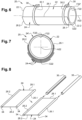
- the pipe 20 comprises at least one stiffening strip 24 placed against the conduit 22, more precisely against the exterior face F22' of the conduit 22, which extends over at least part of the length of the conduit 22. According to a configuration visible on there Figure 6 , the stiffening strip 24 extends over the entire length of the conduit 22. According to another configuration, the stiffening strip 24 extends only over part of the length of the conduit 22. According to another configuration, the pipeline 20 comprises several stiffening strips 24 joined against the same conduit 22 and offset relative to each other along the length of the conduit 22.
- the pipe 20 comprises several stiffening strips 24 superimposed on each other.
- the pipe 20 comprises at least one stiffening strip 24 pressed against the conduit 22, over at least part of the length of the conduit 22, extending in a longitudinal direction substantially parallel to the axis A22 of conduit 22 and presenting, at least in one state, significant stiffness in the longitudinal direction.
- the stiffening strip 24 gives the conduit 22 significant stiffness in the longitudinal direction limiting the risk of collapse of the conduit 22 which remains rectilinear.
- the stiffening strip 24 has, in planes perpendicular to the longitudinal direction, a curvature substantially equal to the curvature of the exterior face F22' of the conduit 22. Due to this curvature, the stiffening strip 24 has a significant moment of inertia in the longitudinal direction, giving it significant stiffness in the longitudinal direction and thus limiting the risks of bending.
- each stiffening strip 24 has a substantially rectangular periphery, comprising first and second lateral edges 26.1, 26.2 substantially parallel to each other and arranged parallel to the axis A22 of the conduit 22 (or to the longitudinal direction) as well than the first and second transverse edges 28.1, 28.2 substantially perpendicular to the first and second side edges 26.1, 26.2.
- the stiffening strip 24 has a first surface F24 intended to be pressed against the conduit 22 and a second surface F24' opposite the first surface F24.
- the stiffening strip 24 has a width (distance separating the first and second lateral edges 26.1, 26.2) substantially equal to or slightly less than half the circumference of the conduit 22. According to one arrangement, each stiffening strip 24 is positioned against the conduit 22 so that the first and second lateral edges 26.1, 26.2 are positioned on either side of the lower generator G22, preferably so that they are substantially symmetrical with respect to the lower generator G22.
- the stiffening strip 24 has a thickness (distance separating the first and second surfaces F24, F24') of the order of a millimeter, between 0.5 and 1.5 mm, a width (distance separating the first and second lateral edges 26.1, 26.2) of the order of 1 to 5 cm and a length (distance separating the first and second transverse edges 28.1, 28.2) greater than 10 cm.
- the pipe 20 comprises at least one connection 30 connecting the stiffening strip 24 and the conduit 22.
- the connection 30 is an adhesive or a film of glue interposed between the stiffening strip 24 and the exterior face F22 ' of the conduit 22.
- the connection 30 comprises clamping collars 30.1, 30.2, distributed between the first and second ends 22.1, 22.2, enclosing the stiffening strip 24 and the conduit 22.
- the stiffening strip 24 is metallic and configured to deform elastically between a rolled state when the cross sections of the stiffening strip 24 are straight, as illustrated in the figure 4 , and an elongated and stiff state when the cross sections of the stiffening strip 24 are curved, the first surface F24 intended to be pressed against the conduit 22 being curved and concave, as illustrated in the Figure 5 .
- This configuration makes it possible to reduce the bulk of the stiffening strip 24 when it is not used.
- the flexible conduit 22 and the stiffening strip 24 can be stored rolled up.
- the stiffening strip 24 comprises at least one longitudinal reinforcement 32, substantially parallel to the longitudinal direction (or to the first or second lateral edge 26.1, 26.2), which extends almost over the entire length of the stiffening strip and has a stiffness important in the longitudinal direction.
- the stiffening strip 24 comprises first and second longitudinal reinforcements 32, 32' positioned respectively at the level of the first and second lateral edges 26.1, 26.2.
- the stiffening strip 24 is made of flexible or semi-rigid plastic material and comprises first and second longitudinal reinforcements 32, 32' positioned respectively at the level of the first and second lateral edges 26.1, 26.2.
- Each of the first and second longitudinal reinforcements 32, 32' comprises a bead 34 integral with the stiffening strip 24, made in one piece with the latter, as well as a rigid tube 36, split along its length, threaded onto the bead 34.
- the bead 34 has a round section.
- the tube 36 has an internal diameter substantially equal to or very slightly greater than the diameter of the bead 34.
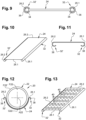
- the stiffening strip 24 is metallic or made of semi-rigid plastic material and comprises first and second longitudinal reinforcements 32, 32' positioned respectively at the level of the first and second lateral edges 26.1, 26.2.
- Each of the first and second lateral edges 26.1, 26.2 has a curved or folded profile 38 forming a longitudinal reinforcement 32, 32'.
- the profile 38 has a C or U-shaped section
- the stiffening strip 24 is hollowed out, as illustrated in the figure 13 .
- the stiffening strip 24 comprises cutouts 40 distributed evenly over the entire surface of the stiffening strip 24.
- the pipe 20 comprises at least one stiffening strip 24' which extends over the entire circumference of the conduit 22, as illustrated in the Figure 7 .
Landscapes
- Engineering & Computer Science (AREA)
- General Engineering & Computer Science (AREA)
- Mechanical Engineering (AREA)
- Textile Engineering (AREA)
- Chemical & Material Sciences (AREA)
- Combustion & Propulsion (AREA)
- Rigid Pipes And Flexible Pipes (AREA)
Abstract
Description
- La présente demande se rapporte à une canalisation comprenant au moins un conduit souple rigidifié ainsi qu'à un aéronef comprenant au moins une telle canalisation.
- Selon un mode de réalisation visible sur la
figure 1 , une canalisation 10 comprend plusieurs conduits 10.1, 10.2, 10.3 positionnés bout à bout et reliés entre eux de manière étanche. La canalisation 10 est reliée à une structure 12 grâce à des colliers de fixation 14 positionnés le long de la canalisation 10, comme au niveau des zones de raccordement des conduits 10.1, 10.2, 10.3 par exemple. La canalisation 10 présente une légère pente P selon une direction allant du premier tronçon 10.1 vers le troisième tronçon 10.3 pour permettre à un liquide de s'écouler par gravité. Selon une configuration, les premier et troisième tronçons 10.1, 10.3 sont métalliques, rigides et conservent la pente P. Pour réduire la masse embarquée dans un aéronef, le deuxième tronçon 10.2 est en matière plastique et souple. En raison de la masse du liquide y circulant et de sa souplesse, le deuxième tronçon 10.2 peut s'affaisser et générer une cuvette 16 au niveau de laquelle peut stagner le liquide. - Par conséquent, pour certaines applications comme les canalisations d'eau potable par exemple, la majorité des tronçons sont métalliques et rigides pour limiter les risques d'apparition de cuvettes même si cela conduit à augmenter la masse embarquée.
- La présente invention vise à remédier à tout ou partie des inconvénients de l'art antérieur.
- A cet effet, l'invention a pour objet une canalisation comprenant au moins un conduit souple présentant un axe, une face intérieure orientée vers l'axe, une face extérieure opposée à la face intérieure, des première et deuxième extrémités, une génératrice inférieure ainsi qu'une longueur correspondant à une distance séparant les première et deuxième extrémités. Selon l'invention, la canalisation comprend au moins une bande de rigidification plaquée contre le conduit sur au moins une partie de sa longueur, s'étendant selon une direction longitudinale sensiblement parallèle à l'axe du conduit et présentant, au moins dans un état, une raideur importante selon la direction longitudinale. En complément, la bande de rigidification est métallique et configurée pour se déformer de manière élastique entre un état enroulé lorsque les sections transversales de la bande de rigidification sont rectilignes et un état allongé et raide lorsque les sections transversales de la bande de rigidification sont courbes, la bande de rigidification présentant une première surface destinée à être plaquée contre le conduit courbe et concave dans l'état allongé et raide
- Même si le conduit en matière plastique est souple, lorsque la bande de rigidification est plaquée contre le conduit, elle lui confère une raideur importante selon la direction longitudinale limitant les risques d'affaissement du conduit.
- Selon d'autres caractéristiques prises isolément ou en combinaison :
- chaque bande de rigidification comprend des premier et deuxième bords latéraux sensiblement parallèles à la direction longitudinale positionnés de part et d'autre de la génératrice inférieure du conduit ;
- les premier et deuxième bords latéraux sont positionnés de manière sensiblement symétrique par rapport à la génératrice inférieure ;
- la canalisation comprend au moins une liaison reliant la bande de rigidification et le conduit ;
- la bande de rigidification est évidée pour réduire sa masse.
- L'invention a également pour objet un aéronef comprenant au moins une canalisation selon l'une des caractéristiques précédentes.
- D'autres caractéristiques et avantages ressortiront de la description de l'invention qui va suivre, description donnée à titre d'exemple uniquement, en regard des dessins annexés parmi lesquels :
- La
figure 1 est une coupe schématique d'un conduit illustrant un mode de réalisation de l'art antérieur, - La
figure 2 est une coupe schématique d'un conduit illustrant un mode de réalisation de l'invention, - La
figure 3 est une coupe transversale selon la ligne III-III de lafigure 2 d'un conduit illustrant un mode de réalisation de l'invention, - La
figure 4 est une vue en perspective d'une bande de rigidification dans un premier état enroulé illustrant un mode de réalisation de l'invention, - La
figure 5 est une vue en perspective d'une bande de rigidification dans un deuxième état allongé et raide illustrant un mode de réalisation de l'invention, - La
figure 6 est une vue en perspective d'un conduit rigidifié illustrant un mode de réalisation de l'invention, - La
figure 7 est une coupe transversale d'un conduit rigidifié illustrant un mode de réalisation de l'invention, - La
figure 8 est une vue en perspective d'une bande de rigidification illustrant un mode de réalisation, - La
figure 9 est une coupe transversale de la bande de rigidification visible sur lafigure 8 , - La
figure 10 est une vue en perspective d'une bande de rigidification illustrant un autre mode de réalisation, - La
figure 11 est une coupe transversale de la bande de rigidification visible sur lafigure 10 , - La
figure 12 est une coupe transversale d'un conduit comportant la bande de rigidification visible sur lafigure 10 , et - La
figure 13 est une vue en perspective d'une bande de rigidification illustrant un autre mode de réalisation. - Selon une application, un aéronef comprend au moins une canalisation 20 configurée pour drainer un liquide, comme de l'eau par exemple. Bien entendu, l'invention n'est pas limitée à cette application.
- La canalisation 20 comprend au moins un conduit 22 souple, en matière plastique par exemple. Ce conduit 22 présente une masse nettement inférieure à celle d'un conduit métallique.
- Selon une configuration, la canalisation 20 comprend plusieurs conduits, dont un conduit 22 souple, positionnés bout à bout et reliés entre eux de manière étanche par des systèmes de raccordement, en matière plastique par exemple. La canalisation 20 est reliée à une structure, comme la structure d'un aéronef, grâce à des colliers de fixation positionnés régulièrement le long de la canalisation 20.
- Les systèmes de raccordement et les colliers de fixation ne sont pas plus décrits car ils peuvent être identiques à ceux de l'art antérieur.
- Comme illustré sur la
figure 6 , le conduit 22 est tubulaire et comprend un axe A22, une face intérieure F22 orientée vers l'axe A22 ainsi qu'une face extérieure F22' opposée à la face intérieure F22 et s'étend entre des première et deuxième extrémités 22.1, 22.2. Selon une configuration, les première et deuxième extrémités 22.1, 22.2 se présentent chacune sous la forme d'un chant annulaire positionné dans un plan transversal sensiblement perpendiculaire à l'axe A22. Le conduit 22 présente une longueur qui correspond à une distance séparant les première et deuxième extrémités 22.1, 22.2 en suivant une génératrice. - En fonctionnement, le conduit 22 comprend une génératrice inférieure G22 qui correspond à la génératrice du conduit 22 la plus basse selon la direction verticale.
- La canalisation 20 comprend au moins une bande de rigidification 24 accolée contre le conduit 22, plus précisément contre la face extérieure F22' du conduit 22, qui s'étend sur au moins une partie de la longueur du conduit 22. Selon une configuration visible sur la
figure 6 , la bande de rigidification 24 s'étend sur toute la longueur du conduit 22. Selon une autre configuration, la bande de rigidification 24 s'étend seulement sur une partie de la longueur du conduit 22. Selon une autre configuration, la canalisation 20 comprend plusieurs bandes de rigidification 24 accolées contre le même conduit 22 et décalées les unes par rapport aux autres selon la longueur du conduit 22. - Selon une autre configuration visible sur la
figure 7 , la canalisation 20 comprend plusieurs bandes de rigidification 24 superposées les unes sur les autres. - Quel que soit le mode de réalisation, la canalisation 20 comprend au moins une bande de rigidification 24 plaquée contre le conduit 22, sur au moins une partie de la longueur du conduit 22, s'étendant selon une direction longitudinale sensiblement parallèle à l'axe A22 du conduit 22 et présentant, au moins dans un état, une raideur importante selon la direction longitudinale. Ainsi, lorsqu'elle est plaquée contre le conduit 22, la bande de rigidification 24 confère au conduit 22 une raideur importante selon la direction longitudinale limitant les risques d'affaissement du conduit 22 qui reste rectiligne.
- Selon une configuration, la bande de rigidification 24 présente, dans des plans perpendiculaires à la direction longitudinale, une courbure sensiblement égale à la courbure de la face extérieure F22' du conduit 22. En raison de cette courbure, la bande de rigidification 24 présente un moment d'inertie important selon la direction longitudinale, lui conférant une raideur importante selon la direction longitudinale et limitant ainsi les risques de flexion. Selon un mode de réalisation, chaque bande de rigidification 24 présente un pourtour sensiblement rectangulaire, comprenant des premier et deuxième bords latéraux 26.1, 26.2 sensiblement parallèles entre eux et agencés parallèlement à l'axe A22 du conduit 22 (ou à la direction longitudinale) ainsi que des premier et deuxième bords transversaux 28.1, 28.2 sensiblement perpendiculaires aux premier et deuxième bords latéraux 26.1, 26.2. La bande de rigidification 24 présente une première surface F24 destinée à être plaquée contre le conduit 22 et une deuxième surface F24' opposée à la première surface F24.
- Selon une configuration, la bande de rigidification 24 présente une largeur (distance séparant les premier et deuxième bords latéraux 26.1, 26.2) sensiblement égale ou légèrement inférieure à une moitié de la circonférence du conduit 22. Selon un agencement, chaque bande de rigidification 24 est positionnée contre le conduit 22 afin que les premier et deuxième bords latéraux 26.1, 26.2 soient positionnés de part et d'autre de la génératrice inférieure G22, de préférence de manière à ce qu'ils soient sensiblement symétriques par rapport à la génératrice inférieure G22.
- Pour donner un ordre de grandeur, la bande de rigidification 24 présente une épaisseur (distance séparant les première et deuxième surfaces F24, F24') de l'ordre du millimètre, comprise entre 0,5 et 1,5 mm, une largeur (distance séparant les premier et deuxième bords latéraux 26.1, 26.2) de l'ordre de 1 à 5 cm et une longueur (distance séparant les premier et deuxième bords transversaux 28.1, 28.2) supérieure à 10 cm.
- La canalisation 20 comprend au moins une liaison 30 reliant la bande de rigidification 24 et le conduit 22. Selon une configuration, la liaison 30 est une colle ou un film de colle intercalé(e) entre la bande de rigidification 24 et la face extérieure F22' du conduit 22. Selon une autre configuration, la liaison 30 comprend des colliers de serrage 30.1, 30.2, répartis entre les première et deuxième extrémités 22.1, 22.2, enserrant la bande de rigidification 24 et le conduit 22.
- Selon une configuration, la bande de rigidification 24 est métallique et configurée pour se déformer de manière élastique entre un état enroulé lorsque les sections transversales de la bande de rigidification 24 sont rectilignes, comme illustré sur la
figure 4 , et un état allongé et raide lorsque les sections transversales de la bande de rigidification 24 sont courbes, la première surface F24 destinée à être plaquée contre le conduit 22 étant courbe et concave, comme illustré sur lafigure 5 . Cette configuration permet de réduire l'encombrement de la bande de rigidification 24 lorsqu'elle n'est pas utilisée. Ainsi, lorsqu'ils ne sont pas utilisés, le conduit 22 souple et la bande de rigidification 24 peuvent être stockés enroulés. - La bande de rigidification 24 comprend au moins un renfort longitudinal 32, sensiblement parallèle à la direction longitudinale (ou au premier ou deuxième bord latéral 26.1, 26.2), qui s'étend quasiment sur toute la longueur de la bande de rigidification et présente une raideur importante selon la direction longitudinale. Selon un agencement, la bande de rigidification 24 comprend des premier et deuxième renforts longitudinaux 32, 32' positionnés respectivement au niveau des premier et deuxième bords latéraux 26.1, 26.2.
- Selon un mode de réalisation visible sur les
figures 8 et9 , la bande de rigidification 24 est en matière plastique souple ou semi-rigide et comprend des premier et deuxième renforts longitudinaux 32, 32' positionnés respectivement au niveau des premier et deuxième bords latéraux 26.1, 26.2. Chacun des premier et deuxième renforts longitudinaux 32, 32' comprend un bourrelet 34 solidaire de la bande de rigidification 24, réalisé d'un seul tenant avec cette dernière, ainsi qu'un tube 36 rigide, fendu sur sa longueur, enfilé sur le bourrelet 34. Le bourrelet 34 présente une section ronde. En complément, le tube 36 présente un diamètre intérieur sensiblement égal ou très légèrement supérieur au diamètre du bourrelet 34. Selon un autre mode de réalisation visible sur lesfigures 10 à 12 , la bande de rigidification 24 est métallique ou en matière plastique semi-rigide et comprend des premier et deuxième renforts longitudinaux 32, 32' positionnés respectivement au niveau des premier et deuxième bords latéraux 26.1, 26.2. Chacun des premier et deuxième bords latéraux 26.1, 26.2 présente un profil 38 recourbé ou plié formant un renfort longitudinal 32, 32'. Selon un mode de réalisation, le profil 38 présente une section en C ou en U - Selon une configuration, pour réduire sa masse, la bande de rigidification 24 est évidée, comme illustré sur la
figure 13 . A titre d'exemple, la bande de rigidification 24 comprend des découpes 40 réparties de manière homogène sur toute la surface de la bande de rigidification 24. - Selon un autre mode de réalisation, la canalisation 20 comprend au moins une bande de rigidification 24' qui s'étend sur toute la circonférence du conduit 22, comme illustré sur la
figure 7 . - Ces différents modes de réalisation permettent de réduire la masse de la canalisation et les coûts de production.
Claims (6)
- Canalisation comprenant au moins un conduit souple (22) présentant un axe (A22), une face intérieure (F22) orientée vers l'axe (A22), une face extérieure (F22') opposée à la face intérieure (F22), des première et deuxième extrémités (22.1, 22.2), une génératrice inférieure (G22) ainsi qu'une longueur correspondant à une distance séparant les première et deuxième extrémités (22.1, 22.), caractérisée en ce que la canalisation comprend au moins une bande de rigidification (24) plaquée contre le conduit (22) sur au moins une partie de sa longueur, s'étendant selon une direction longitudinale sensiblement parallèle à l'axe (A22) du conduit (22) et présentant, au moins dans un état, une raideur importante selon la direction longitudinale et en ce que la bande de rigidification (24) est métallique et configurée pour se déformer de manière élastique entre un état enroulé lorsque les sections transversales de la bande de rigidification (24) sont rectilignes et un état allongé et raide lorsque les sections transversales de la bande de rigidification (24) sont courbes, la bande de rigidification (24) présentant une première surface (F24) destinée à être plaquée contre le conduit (22) courbe et concave dans l'état allongé et raide.
- Canalisation selon la revendication 1, caractérisée en ce que chaque bande de rigidification (24) comprend des premier et deuxième bords latéraux (26.1, 26.2) sensiblement parallèles à la direction longitudinale positionnés de part et d'autre de la génératrice inférieure (G22) du conduit (22).
- Canalisation selon la revendication précédente, caractérisée en ce que les premier et deuxième bords latéraux (26.1, 26.2) sont positionnés de manière sensiblement symétrique par rapport à la génératrice inférieure (G22).
- Canalisation selon l'une des revendications précédentes, caractérisée en ce que la canalisation (20) comprend au moins une liaison (30) reliant la bande de rigidification (24) et le conduit (22).
- Canalisation selon l'une des revendications précédentes, caractérisée en ce que la bande de rigidification (24) est évidée pour réduire sa masse.
- Aéronef comprenant au moins une canalisation selon l'une des revendications précédentes.
Applications Claiming Priority (1)
| Application Number | Priority Date | Filing Date | Title |
|---|---|---|---|
| FR2207592A FR3138177A1 (fr) | 2022-07-25 | 2022-07-25 | Canalisation comprenant au moins un conduit souple rigidifié et aéronef comprenant au moins une telle canalisation |
Publications (2)
| Publication Number | Publication Date |
|---|---|
| EP4311967A1 true EP4311967A1 (fr) | 2024-01-31 |
| EP4311967B1 EP4311967B1 (fr) | 2025-04-30 |
Family
ID=83355354
Family Applications (1)
| Application Number | Title | Priority Date | Filing Date |
|---|---|---|---|
| EP23183232.0A Active EP4311967B1 (fr) | 2022-07-25 | 2023-07-04 | Canalisation comprenant au moins un conduit souple rigidifié et aéronef comprenant au moins une telle canalisation |
Country Status (4)
| Country | Link |
|---|---|
| US (1) | US20240026997A1 (fr) |
| EP (1) | EP4311967B1 (fr) |
| CN (1) | CN117450335A (fr) |
| FR (1) | FR3138177A1 (fr) |
Families Citing this family (2)
| Publication number | Priority date | Publication date | Assignee | Title |
|---|---|---|---|---|
| FR3143008B1 (fr) * | 2022-12-09 | 2024-11-01 | Airbus Helicopters | Aéronef muni d’un moteur et d’un conduit d’échappement autour d’une tuyère d’éjection du moteur |
| US20250164037A1 (en) * | 2023-11-20 | 2025-05-22 | Rectorseal, Llc | Hanger assembly for duct |
Citations (3)
| Publication number | Priority date | Publication date | Assignee | Title |
|---|---|---|---|---|
| US20090194186A1 (en) * | 2008-02-05 | 2009-08-06 | Stefan Gross | Increasing the bending strength of tubes |
| EP2781814A1 (fr) * | 2013-03-19 | 2014-09-24 | J. van Walraven Holding B.V. | Canal de support |
| US20200271241A1 (en) * | 2017-09-13 | 2020-08-27 | J. Van Walraven Holding B.V. | Pipe Support Structure |
Family Cites Families (6)
| Publication number | Priority date | Publication date | Assignee | Title |
|---|---|---|---|---|
| US6691742B1 (en) * | 2003-04-25 | 2004-02-17 | Thomas L. Cooper | Method and apparatus for supporting a pipe |
| US20120111432A1 (en) * | 2010-11-10 | 2012-05-10 | Goodrich Corporation | Aircraft potable water system |
| US8919704B2 (en) * | 2012-12-21 | 2014-12-30 | A. Raymond Et Cie | Conduit hanger and support apparatus |
| US11118721B1 (en) * | 2020-03-04 | 2021-09-14 | Seranum Holdings, Inc. | Pipe insulation shield with adaptive retaining tabs |
| CA3178709A1 (fr) * | 2020-03-30 | 2021-10-07 | Jeffrey A. Hermanson | Systemes de canalisations elliptiques et raccords renforces |
| US11894666B2 (en) * | 2020-12-18 | 2024-02-06 | Cooper Standard Automotive, Inc. | Vehicular conduit retention assembly |
-
2022
- 2022-07-25 FR FR2207592A patent/FR3138177A1/fr not_active Withdrawn
-
2023
- 2023-07-04 EP EP23183232.0A patent/EP4311967B1/fr active Active
- 2023-07-17 US US18/353,278 patent/US20240026997A1/en active Pending
- 2023-07-19 CN CN202310887733.0A patent/CN117450335A/zh active Pending
Patent Citations (3)
| Publication number | Priority date | Publication date | Assignee | Title |
|---|---|---|---|---|
| US20090194186A1 (en) * | 2008-02-05 | 2009-08-06 | Stefan Gross | Increasing the bending strength of tubes |
| EP2781814A1 (fr) * | 2013-03-19 | 2014-09-24 | J. van Walraven Holding B.V. | Canal de support |
| US20200271241A1 (en) * | 2017-09-13 | 2020-08-27 | J. Van Walraven Holding B.V. | Pipe Support Structure |
Also Published As
| Publication number | Publication date |
|---|---|
| US20240026997A1 (en) | 2024-01-25 |
| CN117450335A (zh) | 2024-01-26 |
| EP4311967B1 (fr) | 2025-04-30 |
| FR3138177A1 (fr) | 2024-01-26 |
Similar Documents
| Publication | Publication Date | Title |
|---|---|---|
| EP4311967B1 (fr) | Canalisation comprenant au moins un conduit souple rigidifié et aéronef comprenant au moins une telle canalisation | |
| EP0266270B1 (fr) | Dispositif de fixation étanche d'un tube ou tuyau sur un embout | |
| EP0913613A1 (fr) | Manchon pour élément de tuyauterie | |
| EP0240646A1 (fr) | Collier de serrage | |
| FR2617816A1 (fr) | Installation pour le transport pneumatique de matieres en vrac | |
| EP3309075B1 (fr) | Nacelle d'aeronef comprenant une liaison entre une entree d'air et une motorisation | |
| EP2121362A2 (fr) | Procede d'assemblage par collage d'un vitrage sur son support et moyens pour la mise en oeuvre de ce procede | |
| EP0356363A1 (fr) | Dispositif pour l'appareillage post-opératoire d'une colostomie latérale | |
| EP2551188A1 (fr) | Panneau raidi pour aéronef, comprenant des raidisseurs à ames entaillées | |
| FR3055885A1 (fr) | Nacelle d'aeronef comprenant une liaison entre une entree d'air et une motorisation qui comporte une bride | |
| FR3057545A1 (fr) | Nacelle d'aeronef comprenant une liaison entre un conduit d'une entree d'air et un conduit d'une motorisation | |
| CH706059A2 (fr) | Anneau de raccordement pour conduites tubulaires de fluides sous haute pression. | |
| FR2871214A1 (fr) | Collier de fixation d'un tube ou analogue sur un support | |
| FR3103246A1 (fr) | Assemblage d’au moins un conduit et d’au moins un élément longiligne relié à au moins un support, aéronef comprenant au moins un tel assemblage | |
| FR2751061A1 (fr) | Ecarteur pour petits tubes flexibles d'un echangeur thermique en nappe | |
| EP2775153B1 (fr) | Système de fixation d'un corps sur une paroi | |
| FR2971324A1 (fr) | Piece et dispositif de liaison pour fixer un profile sur un revetement ondule. | |
| EP4375192A1 (fr) | Aéronef comprenant au moins un dispositif d'admission d'air configuré pour limiter l'apparition de bruits aérodynamiques | |
| FR2703818A1 (fr) | Manchon thermorétractable fendu. | |
| EP2722450A1 (fr) | Structure de bâtiment démontable du type métallo-textile | |
| EP4622849A1 (fr) | Dispositif de fixation d'un déflecteur de soubassement à un véhicule automobile | |
| FR2756024A1 (fr) | Nouveau profile en un materiau polymere, destine a etre fixe par clipsage sur des tetes de plots rigides | |
| FR3122459A1 (fr) | Dispositif de raccordement de deux conduits d’une canalisation comprenant au moins un système de raccordement équipé d’un système de guidage longitudinal d’un collier de serrage et canalisation comprenant ledit dispositif de raccordement | |
| FR3024399A1 (fr) | Suspension de vehicule automobile a barre de torsion composite renforcee | |
| FR2684157A1 (fr) | Armature pour joint d'etancheite. |
Legal Events
| Date | Code | Title | Description |
|---|---|---|---|
| PUAI | Public reference made under article 153(3) epc to a published international application that has entered the european phase |
Free format text: ORIGINAL CODE: 0009012 |
|
| STAA | Information on the status of an ep patent application or granted ep patent |
Free format text: STATUS: THE APPLICATION HAS BEEN PUBLISHED |
|
| AK | Designated contracting states |
Kind code of ref document: A1 Designated state(s): AL AT BE BG CH CY CZ DE DK EE ES FI FR GB GR HR HU IE IS IT LI LT LU LV MC ME MK MT NL NO PL PT RO RS SE SI SK SM TR |
|
| STAA | Information on the status of an ep patent application or granted ep patent |
Free format text: STATUS: REQUEST FOR EXAMINATION WAS MADE |
|
| 17P | Request for examination filed |
Effective date: 20240711 |
|
| RBV | Designated contracting states (corrected) |
Designated state(s): AL AT BE BG CH CY CZ DE DK EE ES FI FR GB GR HR HU IE IS IT LI LT LU LV MC ME MK MT NL NO PL PT RO RS SE SI SK SM TR |
|
| RIC1 | Information provided on ipc code assigned before grant |
Ipc: F16L 57/02 20060101ALI20241028BHEP Ipc: F16L 3/26 20060101ALI20241028BHEP Ipc: F16L 11/10 20060101ALI20241028BHEP Ipc: F16L 3/02 20060101AFI20241028BHEP |
|
| GRAP | Despatch of communication of intention to grant a patent |
Free format text: ORIGINAL CODE: EPIDOSNIGR1 |
|
| STAA | Information on the status of an ep patent application or granted ep patent |
Free format text: STATUS: GRANT OF PATENT IS INTENDED |
|
| INTG | Intention to grant announced |
Effective date: 20241209 |
|
| RIN1 | Information on inventor provided before grant (corrected) |
Inventor name: MILLET, GERARD Inventor name: DELPY, VINCENT Inventor name: FOUCART-GAUDY, SIMON |
|
| GRAS | Grant fee paid |
Free format text: ORIGINAL CODE: EPIDOSNIGR3 |
|
| GRAA | (expected) grant |
Free format text: ORIGINAL CODE: 0009210 |
|
| STAA | Information on the status of an ep patent application or granted ep patent |
Free format text: STATUS: THE PATENT HAS BEEN GRANTED |
|
| AK | Designated contracting states |
Kind code of ref document: B1 Designated state(s): AL AT BE BG CH CY CZ DE DK EE ES FI FR GB GR HR HU IE IS IT LI LT LU LV MC ME MK MT NL NO PL PT RO RS SE SI SK SM TR |
|
| REG | Reference to a national code |
Ref country code: CH Ref legal event code: EP Ref country code: GB Ref legal event code: FG4D Free format text: NOT ENGLISH |
|
| REG | Reference to a national code |
Ref country code: DE Ref legal event code: R096 Ref document number: 602023003160 Country of ref document: DE |
|
| REG | Reference to a national code |
Ref country code: IE Ref legal event code: FG4D Free format text: LANGUAGE OF EP DOCUMENT: FRENCH |
|
| REG | Reference to a national code |
Ref country code: NL Ref legal event code: MP Effective date: 20250430 |
|
| REG | Reference to a national code |
Ref country code: AT Ref legal event code: MK05 Ref document number: 1790283 Country of ref document: AT Kind code of ref document: T Effective date: 20250430 |
|
| PG25 | Lapsed in a contracting state [announced via postgrant information from national office to epo] |
Ref country code: FI Free format text: LAPSE BECAUSE OF FAILURE TO SUBMIT A TRANSLATION OF THE DESCRIPTION OR TO PAY THE FEE WITHIN THE PRESCRIBED TIME-LIMIT Effective date: 20250430 Ref country code: PT Free format text: LAPSE BECAUSE OF FAILURE TO SUBMIT A TRANSLATION OF THE DESCRIPTION OR TO PAY THE FEE WITHIN THE PRESCRIBED TIME-LIMIT Effective date: 20250901 Ref country code: ES Free format text: LAPSE BECAUSE OF FAILURE TO SUBMIT A TRANSLATION OF THE DESCRIPTION OR TO PAY THE FEE WITHIN THE PRESCRIBED TIME-LIMIT Effective date: 20250430 |
|
| PGFP | Annual fee paid to national office [announced via postgrant information from national office to epo] |
Ref country code: DE Payment date: 20250722 Year of fee payment: 3 |
|
| REG | Reference to a national code |
Ref country code: LT Ref legal event code: MG9D |
|
| PG25 | Lapsed in a contracting state [announced via postgrant information from national office to epo] |
Ref country code: NO Free format text: LAPSE BECAUSE OF FAILURE TO SUBMIT A TRANSLATION OF THE DESCRIPTION OR TO PAY THE FEE WITHIN THE PRESCRIBED TIME-LIMIT Effective date: 20250730 Ref country code: GR Free format text: LAPSE BECAUSE OF FAILURE TO SUBMIT A TRANSLATION OF THE DESCRIPTION OR TO PAY THE FEE WITHIN THE PRESCRIBED TIME-LIMIT Effective date: 20250731 |
|
| PG25 | Lapsed in a contracting state [announced via postgrant information from national office to epo] |
Ref country code: NL Free format text: LAPSE BECAUSE OF FAILURE TO SUBMIT A TRANSLATION OF THE DESCRIPTION OR TO PAY THE FEE WITHIN THE PRESCRIBED TIME-LIMIT Effective date: 20250430 Ref country code: PL Free format text: LAPSE BECAUSE OF FAILURE TO SUBMIT A TRANSLATION OF THE DESCRIPTION OR TO PAY THE FEE WITHIN THE PRESCRIBED TIME-LIMIT Effective date: 20250430 |
|
| PG25 | Lapsed in a contracting state [announced via postgrant information from national office to epo] |
Ref country code: BG Free format text: LAPSE BECAUSE OF FAILURE TO SUBMIT A TRANSLATION OF THE DESCRIPTION OR TO PAY THE FEE WITHIN THE PRESCRIBED TIME-LIMIT Effective date: 20250430 |
|
| PG25 | Lapsed in a contracting state [announced via postgrant information from national office to epo] |
Ref country code: HR Free format text: LAPSE BECAUSE OF FAILURE TO SUBMIT A TRANSLATION OF THE DESCRIPTION OR TO PAY THE FEE WITHIN THE PRESCRIBED TIME-LIMIT Effective date: 20250430 |
|
| PG25 | Lapsed in a contracting state [announced via postgrant information from national office to epo] |
Ref country code: AT Free format text: LAPSE BECAUSE OF FAILURE TO SUBMIT A TRANSLATION OF THE DESCRIPTION OR TO PAY THE FEE WITHIN THE PRESCRIBED TIME-LIMIT Effective date: 20250430 |
|
| PGFP | Annual fee paid to national office [announced via postgrant information from national office to epo] |
Ref country code: FR Payment date: 20250725 Year of fee payment: 3 |
|
| PG25 | Lapsed in a contracting state [announced via postgrant information from national office to epo] |
Ref country code: RS Free format text: LAPSE BECAUSE OF FAILURE TO SUBMIT A TRANSLATION OF THE DESCRIPTION OR TO PAY THE FEE WITHIN THE PRESCRIBED TIME-LIMIT Effective date: 20250731 |
|
| PG25 | Lapsed in a contracting state [announced via postgrant information from national office to epo] |
Ref country code: IS Free format text: LAPSE BECAUSE OF FAILURE TO SUBMIT A TRANSLATION OF THE DESCRIPTION OR TO PAY THE FEE WITHIN THE PRESCRIBED TIME-LIMIT Effective date: 20250830 |
|
| PG25 | Lapsed in a contracting state [announced via postgrant information from national office to epo] |
Ref country code: LV Free format text: LAPSE BECAUSE OF FAILURE TO SUBMIT A TRANSLATION OF THE DESCRIPTION OR TO PAY THE FEE WITHIN THE PRESCRIBED TIME-LIMIT Effective date: 20250430 |
|
| PG25 | Lapsed in a contracting state [announced via postgrant information from national office to epo] |
Ref country code: DK Free format text: LAPSE BECAUSE OF FAILURE TO SUBMIT A TRANSLATION OF THE DESCRIPTION OR TO PAY THE FEE WITHIN THE PRESCRIBED TIME-LIMIT Effective date: 20250430 Ref country code: SM Free format text: LAPSE BECAUSE OF FAILURE TO SUBMIT A TRANSLATION OF THE DESCRIPTION OR TO PAY THE FEE WITHIN THE PRESCRIBED TIME-LIMIT Effective date: 20250430 |
|
| PG25 | Lapsed in a contracting state [announced via postgrant information from national office to epo] |
Ref country code: CZ Free format text: LAPSE BECAUSE OF FAILURE TO SUBMIT A TRANSLATION OF THE DESCRIPTION OR TO PAY THE FEE WITHIN THE PRESCRIBED TIME-LIMIT Effective date: 20250430 |
|
| PG25 | Lapsed in a contracting state [announced via postgrant information from national office to epo] |
Ref country code: EE Free format text: LAPSE BECAUSE OF FAILURE TO SUBMIT A TRANSLATION OF THE DESCRIPTION OR TO PAY THE FEE WITHIN THE PRESCRIBED TIME-LIMIT Effective date: 20250430 |
|
| PG25 | Lapsed in a contracting state [announced via postgrant information from national office to epo] |
Ref country code: SK Free format text: LAPSE BECAUSE OF FAILURE TO SUBMIT A TRANSLATION OF THE DESCRIPTION OR TO PAY THE FEE WITHIN THE PRESCRIBED TIME-LIMIT Effective date: 20250430 |
|
| PG25 | Lapsed in a contracting state [announced via postgrant information from national office to epo] |
Ref country code: IT Free format text: LAPSE BECAUSE OF FAILURE TO SUBMIT A TRANSLATION OF THE DESCRIPTION OR TO PAY THE FEE WITHIN THE PRESCRIBED TIME-LIMIT Effective date: 20250430 |
|
| REG | Reference to a national code |
Ref country code: DE Ref legal event code: R097 Ref document number: 602023003160 Country of ref document: DE |
|
| PG25 | Lapsed in a contracting state [announced via postgrant information from national office to epo] |
Ref country code: RO Free format text: LAPSE BECAUSE OF FAILURE TO SUBMIT A TRANSLATION OF THE DESCRIPTION OR TO PAY THE FEE WITHIN THE PRESCRIBED TIME-LIMIT Effective date: 20250430 |
|
| PLBE | No opposition filed within time limit |
Free format text: ORIGINAL CODE: 0009261 |
|
| STAA | Information on the status of an ep patent application or granted ep patent |
Free format text: STATUS: NO OPPOSITION FILED WITHIN TIME LIMIT |
|
| REG | Reference to a national code |
Ref country code: CH Ref legal event code: L10 Free format text: ST27 STATUS EVENT CODE: U-0-0-L10-L00 (AS PROVIDED BY THE NATIONAL OFFICE) Effective date: 20260311 |
|
| PG25 | Lapsed in a contracting state [announced via postgrant information from national office to epo] |
Ref country code: LU Free format text: LAPSE BECAUSE OF NON-PAYMENT OF DUE FEES Effective date: 20250704 |
|
| REG | Reference to a national code |
Ref country code: BE Ref legal event code: MM Effective date: 20250731 |
|
| 26N | No opposition filed |
Effective date: 20260202 |
|
| PG25 | Lapsed in a contracting state [announced via postgrant information from national office to epo] |
Ref country code: BE Free format text: LAPSE BECAUSE OF NON-PAYMENT OF DUE FEES Effective date: 20250731 |