EP4311966A1 - Electromagnetic valve and electromagnetic valve assembly - Google Patents
Electromagnetic valve and electromagnetic valve assembly Download PDFInfo
- Publication number
- EP4311966A1 EP4311966A1 EP22773915.8A EP22773915A EP4311966A1 EP 4311966 A1 EP4311966 A1 EP 4311966A1 EP 22773915 A EP22773915 A EP 22773915A EP 4311966 A1 EP4311966 A1 EP 4311966A1
- Authority
- EP
- European Patent Office
- Prior art keywords
- valve
- mounting base
- magnetic conductive
- conductive frame
- electromagnetic valve
- Prior art date
- Legal status (The legal status is an assumption and is not a legal conclusion. Google has not performed a legal analysis and makes no representation as to the accuracy of the status listed.)
- Pending
Links
Images




Classifications
-
- F—MECHANICAL ENGINEERING; LIGHTING; HEATING; WEAPONS; BLASTING
- F16—ENGINEERING ELEMENTS AND UNITS; GENERAL MEASURES FOR PRODUCING AND MAINTAINING EFFECTIVE FUNCTIONING OF MACHINES OR INSTALLATIONS; THERMAL INSULATION IN GENERAL
- F16K—VALVES; TAPS; COCKS; ACTUATING-FLOATS; DEVICES FOR VENTING OR AERATING
- F16K31/00—Actuating devices; Operating means; Releasing devices
- F16K31/02—Actuating devices; Operating means; Releasing devices electric; magnetic
- F16K31/06—Actuating devices; Operating means; Releasing devices electric; magnetic using a magnet, e.g. diaphragm valves, cutting off by means of a liquid
- F16K31/0675—Electromagnet aspects, e.g. electric supply therefor
-
- F—MECHANICAL ENGINEERING; LIGHTING; HEATING; WEAPONS; BLASTING
- F16—ENGINEERING ELEMENTS AND UNITS; GENERAL MEASURES FOR PRODUCING AND MAINTAINING EFFECTIVE FUNCTIONING OF MACHINES OR INSTALLATIONS; THERMAL INSULATION IN GENERAL
- F16K—VALVES; TAPS; COCKS; ACTUATING-FLOATS; DEVICES FOR VENTING OR AERATING
- F16K31/00—Actuating devices; Operating means; Releasing devices
- F16K31/02—Actuating devices; Operating means; Releasing devices electric; magnetic
- F16K31/06—Actuating devices; Operating means; Releasing devices electric; magnetic using a magnet, e.g. diaphragm valves, cutting off by means of a liquid
- F16K31/0644—One-way valve
-
- B—PERFORMING OPERATIONS; TRANSPORTING
- B60—VEHICLES IN GENERAL
- B60H—ARRANGEMENTS OF HEATING, COOLING, VENTILATING OR OTHER AIR-TREATING DEVICES SPECIALLY ADAPTED FOR PASSENGER OR GOODS SPACES OF VEHICLES
- B60H1/00—Heating, cooling or ventilating devices
-
- F—MECHANICAL ENGINEERING; LIGHTING; HEATING; WEAPONS; BLASTING
- F16—ENGINEERING ELEMENTS AND UNITS; GENERAL MEASURES FOR PRODUCING AND MAINTAINING EFFECTIVE FUNCTIONING OF MACHINES OR INSTALLATIONS; THERMAL INSULATION IN GENERAL
- F16K—VALVES; TAPS; COCKS; ACTUATING-FLOATS; DEVICES FOR VENTING OR AERATING
- F16K1/00—Lift valves or globe valves, i.e. cut-off apparatus with closure members having at least a component of their opening and closing motion perpendicular to the closing faces
- F16K1/32—Details
- F16K1/34—Cutting-off parts, e.g. valve members, seats
- F16K1/36—Valve members
-
- F—MECHANICAL ENGINEERING; LIGHTING; HEATING; WEAPONS; BLASTING
- F16—ENGINEERING ELEMENTS AND UNITS; GENERAL MEASURES FOR PRODUCING AND MAINTAINING EFFECTIVE FUNCTIONING OF MACHINES OR INSTALLATIONS; THERMAL INSULATION IN GENERAL
- F16K—VALVES; TAPS; COCKS; ACTUATING-FLOATS; DEVICES FOR VENTING OR AERATING
- F16K1/00—Lift valves or globe valves, i.e. cut-off apparatus with closure members having at least a component of their opening and closing motion perpendicular to the closing faces
- F16K1/32—Details
- F16K1/34—Cutting-off parts, e.g. valve members, seats
- F16K1/42—Valve seats
-
- F—MECHANICAL ENGINEERING; LIGHTING; HEATING; WEAPONS; BLASTING
- F16—ENGINEERING ELEMENTS AND UNITS; GENERAL MEASURES FOR PRODUCING AND MAINTAINING EFFECTIVE FUNCTIONING OF MACHINES OR INSTALLATIONS; THERMAL INSULATION IN GENERAL
- F16K—VALVES; TAPS; COCKS; ACTUATING-FLOATS; DEVICES FOR VENTING OR AERATING
- F16K27/00—Construction of housing; Use of materials therefor
- F16K27/02—Construction of housing; Use of materials therefor of lift valves
- F16K27/029—Electromagnetically actuated valves
-
- F—MECHANICAL ENGINEERING; LIGHTING; HEATING; WEAPONS; BLASTING
- F16—ENGINEERING ELEMENTS AND UNITS; GENERAL MEASURES FOR PRODUCING AND MAINTAINING EFFECTIVE FUNCTIONING OF MACHINES OR INSTALLATIONS; THERMAL INSULATION IN GENERAL
- F16K—VALVES; TAPS; COCKS; ACTUATING-FLOATS; DEVICES FOR VENTING OR AERATING
- F16K31/00—Actuating devices; Operating means; Releasing devices
- F16K31/02—Actuating devices; Operating means; Releasing devices electric; magnetic
- F16K31/06—Actuating devices; Operating means; Releasing devices electric; magnetic using a magnet, e.g. diaphragm valves, cutting off by means of a liquid
- F16K31/0644—One-way valve
- F16K31/0655—Lift valves
-
- H—ELECTRICITY
- H01—ELECTRIC ELEMENTS
- H01F—MAGNETS; INDUCTANCES; TRANSFORMERS; SELECTION OF MATERIALS FOR THEIR MAGNETIC PROPERTIES
- H01F7/00—Magnets
- H01F7/06—Electromagnets; Actuators including electromagnets
- H01F7/08—Electromagnets; Actuators including electromagnets with armatures
- H01F7/126—Supporting or mounting
-
- F—MECHANICAL ENGINEERING; LIGHTING; HEATING; WEAPONS; BLASTING
- F16—ENGINEERING ELEMENTS AND UNITS; GENERAL MEASURES FOR PRODUCING AND MAINTAINING EFFECTIVE FUNCTIONING OF MACHINES OR INSTALLATIONS; THERMAL INSULATION IN GENERAL
- F16K—VALVES; TAPS; COCKS; ACTUATING-FLOATS; DEVICES FOR VENTING OR AERATING
- F16K31/00—Actuating devices; Operating means; Releasing devices
- F16K31/12—Actuating devices; Operating means; Releasing devices actuated by fluid
- F16K31/36—Actuating devices; Operating means; Releasing devices actuated by fluid in which fluid from the circuit is constantly supplied to the fluid motor
- F16K31/40—Actuating devices; Operating means; Releasing devices actuated by fluid in which fluid from the circuit is constantly supplied to the fluid motor with electrically-actuated member in the discharge of the motor
-
- F—MECHANICAL ENGINEERING; LIGHTING; HEATING; WEAPONS; BLASTING
- F16—ENGINEERING ELEMENTS AND UNITS; GENERAL MEASURES FOR PRODUCING AND MAINTAINING EFFECTIVE FUNCTIONING OF MACHINES OR INSTALLATIONS; THERMAL INSULATION IN GENERAL
- F16K—VALVES; TAPS; COCKS; ACTUATING-FLOATS; DEVICES FOR VENTING OR AERATING
- F16K31/00—Actuating devices; Operating means; Releasing devices
- F16K31/12—Actuating devices; Operating means; Releasing devices actuated by fluid
- F16K31/36—Actuating devices; Operating means; Releasing devices actuated by fluid in which fluid from the circuit is constantly supplied to the fluid motor
- F16K31/40—Actuating devices; Operating means; Releasing devices actuated by fluid in which fluid from the circuit is constantly supplied to the fluid motor with electrically-actuated member in the discharge of the motor
- F16K31/406—Actuating devices; Operating means; Releasing devices actuated by fluid in which fluid from the circuit is constantly supplied to the fluid motor with electrically-actuated member in the discharge of the motor acting on a piston
- F16K31/408—Actuating devices; Operating means; Releasing devices actuated by fluid in which fluid from the circuit is constantly supplied to the fluid motor with electrically-actuated member in the discharge of the motor acting on a piston the discharge being effected through the piston and being blockable by an electrically-actuated member making contact with the piston
Definitions
- the present invention generally relates to the field of vehicle components, and in particular, to an electromagnetic valve and an electromagnetic valve assembly.
- an electromagnetic valve is commonly used in the field of vehicle components for opening and closing a flow path of an air conditioning system.
- the electromagnetic valve and corresponding components of the air conditioning system must be assembled as an integral structure.
- the assembly of the electromagnetic valve is complex, and orientations of an electromagnetic driving assembly and a magnetic conductive frame in the electromagnetic valve are difficult to position, resulting in low efficiency of the assembly.
- an electromagnetic valve and an electromagnetic valve assembly are provided.
- An electromagnetic valve is mounted on a mounting base, and the electromagnetic valve includes a valve body, a magnetic conductive frame, and an electromagnetic driving assembly;
- the positioning member is disposed on the magnetic conductive frame, during an assembly process, it may realize rapid positioning of orientations of the electromagnetic driving assembly and the magnetic conductive frame, rapidly realize fixation of the electromagnetic driving assembly, improve assembly efficiency, ensure stability of the electromagnetic valve in an applying process, and prevent the electromagnetic driving assembly from deviating in orientation and even shifting relative to the mounting base.
- the positioning member includes a pin of the magnetic conductive frame extending towards the mounting base.
- the pin is in a shape of a L.
- an end of the pin away from the magnetic conductive frame is bent to define as a bent portion, and the bent portion is provided with a first through hole.
- the electromagnetic valve further includes a connecting member, which penetrates through the first through hole and is connected to the mounting base.
- the bent portion abuts against the mounting base.
- the bent portion of the pin may just abut against the mounting base, and the bent portion and the mounting base may cooperate with each other to reduce difficulty of assembly.
- the mounting base may play a certain supportive role for the magnetic conductive frame, and the assembly may be more stable.
- the valve seat further includes a clamping portion, which is provided proximal to the magnetic conductive frame, and a part of the clamping portion protrudes from the mounting base along an axial direction of the valve seat; and the positioning member is provided at an end of the magnetic conductive frame proximal to the valve seat, and the part of the clamping portion protruding from the mounting base along the axial direction of the valve seat has the same height as the positioning member.
- the clamping portion may be set to protrude from the mounting base, which facilitates forcing to a protruding part for mounting.
- the part of the clamping portion protruding from the mounting base has the same height as the positioning member, so that the positioning member is exactly in contact with the mounting base and is connected to the mounting base after the assembly is completed, which reduces a height of the electromagnetic valve and the mounting base after the assembly and decreases occupied space.
- the positioning member and the magnetic conductive frame are an integral construction.
- the positioning member and the magnetic conductive frame are an integral construction, which reduces assembly steps and enables a connection between the positioning member and the magnetic conductive frame more stable.
- the electromagnetic valve further includes a blocking assembly
- the valve seat is provided with a valve port
- the blocking assembly is disposed in the valve seat and is capable of opening and closing the valve port when the blocking assembly is driven by the electromagnetic driving assembly.
- the present invention further provides an electromagnetic valve assembly, including a mounting base and any one of electromagnetic valves described above, and at least a part of the electromagnetic valve is mounted in the mounting base.
- the mounting base is provided with a mounting portion corresponding to the positioning member, and the positioning member cooperates with the mounting portion to limit rotation of the magnetic conductive frame.
- the mounting base is provided with the mounting portion, and the positioning member may cooperate with the mounting portion to realize rapid connection during assembly, simplifying the assembly steps and improving the assembly efficiency.
- the electromagnetic valve may realize rapid positioning of orientations of the electromagnetic driving assembly and the magnetic conductive frame during the assembly process by disposing the positioning member on the magnetic conductive frame, rapidly realize fixation of the electromagnetic driving assembly, improve the assembly efficiency, ensure stability of the electromagnetic valve in the applying process, and prevent the electromagnetic driving assembly from deviating in orientation and even shifting relative to the mounting base.
- 100 represents an electromagnetic valve
- 1 represents a valve seat
- 11 represents a first cavity
- 12 represents a clamping portion
- 121 represents a clamping plane
- 13 represents a connecting portion
- 131 represents a first threaded portion
- 14 represents an inlet flow channel
- 15 represents an outlet flow channel
- 16 represents a valve port
- 2 represents a magnetic conductive frame
- 21 represents a positioning member
- 22 represents a bent portion
- 23 represents a first through hole
- 24 represents a connecting member
- 3 represents an electromagnetic driving assembly
- 31 represents a sleeve
- 32 represents an electromagnetic coil
- 33 represents a stator
- 34 represents an actuator
- 341 represents a third cavity
- 35 represents a valve needle
- 36 represents a first elastic member
- 37 represents an elastic member of a valve needle
- 4 represents a valve cover
- 5 represents a mounting base
- 52 represents a mounting portion
- 6 represents a blocking assembly
- 61 represents a blocking body
- 62 represents a
- an assembly when an assembly is considered to be “disposed on” another assembly, it can be directly disposed to another assembly, or there can be a centered assembly.
- an assembly When an assembly is considered to be “set on” another assembly, it can be directly set on another assembly, or there can be a centered assembly at the same time.
- an assembly When an assembly is considered to be “fixed to” another assembly, it can be directly fixed to another assembly, or there can be a centered assembly at the same time.
- the present invention provides an electromagnetic valve 100, which is mounted on a mounting base 5.
- the electromagnetic valve 100 is configured to control on/off of medium or a magnitude of medium flow in a pipeline.
- the electromagnetic valve 100 includes a valve body, a magnetic conductive frame 2, and an electromagnetic driving assembly 3.
- the valve body at least includes a valve seat 1, the magnetic conductive frame 2 is fixed to the valve seat 1, and the electromagnetic driving assembly 3 is mounted in the magnetic conductive frame 2.
- the magnetic conductive frame 2 is provided with a positioning member 21, after the electromagnetic valve 100 is mounted on the mounting base 5, the positioning member 21 is capable of being connected to the mounting base 5 so as to restrict the electromagnetic driving assembly 3 from rotating relative to the mounting base 5.
- it may rapidly realize fixation of the electromagnetic driving assembly 3 and improve overall assembly efficiency. Meanwhile, it may be prevented that the electromagnetic driving assembly 3 deviates in orientation in an applying process and even shifts relative to the mounting base 5, and it may ensure stability of the electromagnetic valve 100 in the applying process.
- the positioning member 21 may include a pin of the magnetic conductive frame 2 extending towards the mounting base 5.
- the orientation of the electromagnetic driving assembly 3 and the magnetic conductive frame 2 may be determined according to specific mounting requirements. By restricting the pin to the mounting base 5, orientations of the electromagnetic driving assembly 3 and the magnetic conductive frame 2 may be rapidly positioned and fixed to prevent the electromagnetic driving assembly 3 and the magnetic conductive frame 2 from rotating or deflecting relative to the mounting base 5.
- a specific structure of the positioning member 21 may be not limited to the above description. For example, it may also be a protruding structure set on the magnetic conductive frame 2 or a snap structure that may cooperate with and be connected to the mounting base 5.
- the pin may be L shaped.
- An end of a L-shaped pin may be connected to the magnetic conductive frame 2, and another end may be connected to the mounting base 5 to realize the positioning of the orientation of the magnetic conductive frame 2.
- a specific structural form of the pin is not limited to the shape of L, but may also be other shapes, such as a shape of C and the like.
- an end of the pin away from the magnetic conductive frame 2 may be bent to define as a bent portion 22, and the bent portion 22 is provided with a first through hole 23.
- the electromagnetic valve 100 may further include a connecting member 24, which may penetrate through the first through hole 23 and be connected to the mounting base 5.
- the connecting member 24 may be a bolt or a dowel, etc.
- the bent portion 22 may abut against the mounting base 5.
- the bent portion 22 of the pin may just abut against the mounting base 5, and the bent portion 22 and the mounting base 5 may cooperate with each other to reduce difficulty of assembly.
- the mounting base 5 may play a certain supportive role for the magnetic conductive frame 2, and the assembly may be more stable.
- a gap may exist between the bent portion 22 and the mounting base 5.
- the valve seat 1 may further include a clamping portion 12, which is provided proximal to the magnetic conductive frame 2, and a part of the clamping portion 12 may protrude from the mounting base 5 along an axial direction of the valve seat 1.
- the positioning member 21 is provided at an end of the magnetic conductive frame 2 proximal to the valve seat 1, and the part of the clamping portion 12 protruding from the mounting base 5 along the axial direction of the valve seat 1 may have the same height as the positioning member 21.
- the part of the clamping portion 12 protruding from the mounting base 5 may have the same height as the positioning member 21, so that the positioning member 21 may be exactly in contact with the mounting base 5 and is connected to the mounting base 5 after the assembly is completed, and the valve seat 1 may also abut against the magnetic conductive frame 2, reducing a height of the electromagnetic valve 100 and the mounting base 5 after the assembly and decreasing occupied space. Heights of a plurality of members may be adapted to match each other, allowing the assembly of the electromagnetic valve 100 and the mounting base 5 rapider and more aesthetically pleasing. In other embodiments, the height of the clamping portion 12 and the height of the positioning member 21 may be not limited, and the height of the clamping portion 12 may be not equal to the height of the positioning member 21.
- the clamping portion 12 is provided with at least two clamping planes 121, and an external mounting tool may cooperate with the clamping planes to realize a connection between the valve seat 1 and the mounting base 5 to be tightened, so as to improve the assembly efficiency.
- a plurality of clamping planes 121 such as six clamping planes 121, are provided on the clamping portion 12 of the valve seat 1, and the plurality of clamping planes 121 are distributed equally circumferentially around the valve seat 1. In other embodiments, the number of clamping planes 121 may be not limited.
- the positioning member 21 and the magnetic conductive frame 2 may be an integral construction, resulting in reducing assembly steps between the positioning member 21 and the magnetic conductive frame 2, and the integral construction may enable a connection between the positioning member 21 and the magnetic conductive frame 2 more stable.
- the positioning member 21 and the magnetic conductive frame 2 may be split constructions.
- the present invention further provides an electromagnetic valve assembly 200.
- the electromagnetic valve assembly 200 includes a mounting base 5 and any one of the above electromagnetic valves, and the electromagnetic valve is mounted in the mounting base 5.
- the mounting base 5 is provided with a mounting portion 52 corresponding to the positioning member 21, and the positioning member 21 may cooperate with the mounting portion 52 to limit rotation of the magnetic conductive frame 2.
- the mounting portion 52 may be a groove disposed on the mounting base 5, and the pin may be inserted into the groove correspondingly to rapidly complete the positioning of the orientation of the magnetic conductive frame 2 when assembling.
- the number of the groove may be not limited. For example, a plurality of grooves may be disposed, and the pin may be inserted into a corresponding groove according to a desired orientation of the magnetic conductive frame 2. Referring to FIG.
- the mounting portion 52 may also be a through hole disposed on the mounting base 5, and an end of the connecting member 24 may penetrate through the first through hole 23 of the bent portion 22 and be inserted into the through hole of the mounting base 5, realizing a limitation of the orientation of the magnetic conductive frame 2.
- the connecting member 24 may be a bolt or a dowel, etc.
- an end of the connecting member 24 proximal to the bent portion 22 may abut against the bent portion 22, realizing an axial limitation of the bent portion 22 and preventing the positioning member 21 from moving along an axial direction of the valve seat 1 and back towards the mounting base 5 and detaching from the mounting base 5.
- the clamping portion 12 and a connecting portion 13 may be sequentially provided along the axial direction of the valve seat 1 top-down.
- An outer side wall of the connecting portion 13 may be provided with a first threaded portion 131
- the corresponding mounting base 5 may be provided with a second threaded portion
- the first threaded portion 131 may be connected to the second threaded portion to realize a rapid assembly of the valve seat 1 and the mounting base 5.
- the valve body may further include a valve cover 4, the valve seat 1 is provided with a first cavity 11, an outer side wall of the valve cover 4 is sealingly connected to an inner wall side of the first cavity 11, and the valve cover 4 may have no relative sliding with the valve seat 1.
- the magnetic conductive frame 2 may be mounted on the valve seat 1 and the valve cover 4 and a lower end surface of the magnetic conductive frame 2 may abut against the valve seat 1 and the valve cover 4.
- the valve seat 1 is provided with an inlet flow channel 14 and an outlet flow channel 15 which are connected to and in communication with a valve port 16 and the first cavity 11. Opening and closing of the valve port 16 may control communication and closure between the inlet flow channel 14 and the outlet flow channel 15.
- the electromagnetic valve may further include a blocking assembly 6, the valve seat 1 is provided with a valve port 16, and the blocking assembly 6 is disposed in the valve seat 1 and is capable of opening and closing the valve port 16 when the blocking assembly 6 is driven by the electromagnetic driving assembly 3.
- an end of the valve cover 4 away from the magnetic conductive frame 2 is provided with a second cavity configured for accommodating the blocking assembly 6, and an end of the blocking assembly 6 proximal to the magnetic conductive frame 2 may be sealingly and slidingly connected to a cavity wall of the second cavity.
- the blocking assembly 6 may include a blocking body 61 and a second elastic member 62, an end of the blocking body 61 may be accommodated in the second cavity, and another end of the blocking body 61 is configured for blocking the valve port 16.
- An end of the second elastic member 62 may abut against an end of the blocking body 61 proximal to the magnetic conductive frame 2, and another end of the second elastic member 62 may abut against an end of the first cavity 11 away from the magnetic conductive frame 2.
- the second elastic member 62 is configured to open the valve so that resilient recovery drives the blocking body 61 to move towards the magnetic conductive frame 2 for opening the valve port 16.
- the electromagnetic driving assembly 3 may include an electromagnetic unit and a valve needle unit.
- the electromagnetic unit may drive the valve needle 35 to move back towards the blocking body 61 to open the valve when the electromagnetic unit is energized.
- the blocking body 61 may move towards the valve port 16 until the blocking body 61 seals against the valve port 16 to close the valve port 16.
- an end of the blocking body 61 proximal to the valve needle 35 is provided with a pilot valve port 63, the valve needle 35 may be driven by the electromagnetic unit to open and close the pilot valve port 63.
- a pressure of a side of the blocking assembly 6 proximal to the valve needle 35 may be less than a pressure of a side of the blocking assembly 6 proximal to the valve port 16.
- the electromagnetic unit may include an electromagnetic coil 32, a stator 33 that is stationary with respect to the electromagnetic coil 32, and an actuator 34 that is movable along an axial direction of the valve seat 1.
- the electromagnetic coil 32 may be sheathed outside the stator 33 and the actuator 34.
- a first elastic member 36 is further provided between the stator 33 and the actuator 34, the actuator 34 is provided with a third cavity 341 penetrating through the actuator 34 along an axial direction, the first elastic member 36 may be at least partially movable in the third cavity 341, and the first elastic member 36 may resiliently recover to drive the valve needle unit to move towards the blocking body 61, so as to drive the blocking body 61 to move towards the valve port 16 to close the valve port 16.
- the electromagnetic coil 32 may be fixed in the magnetic conductive frame 2.
- the electromagnetic driving assembly may further include a sleeve 31, and an end of the sleeve 31 proximal to the valve seat 1 may extend out of the magnetic conductive frame 2 and be fixedly connected to the valve cover 4.
- the stator 33 may be fixed to an end of the sleeve 31 away from the valve seat 1, the actuator 34 may be movable inside the sleeve 31, and the electromagnetic coil 32 may be sheathed outside the sleeve 31.
- the valve needle unit may include a valve needle 35 and an elastic member of the valve needle 35.
- the valve needle 35 may be movable in the third cavity 341, an end of the elastic member of the valve needle 35 may abut against an end of the valve needle 35 proximal to the stator 33, and another end of the elastic member of the valve needle 35 may abut against an end of the third cavity 341 proximal to the valve seat 1.
- a process of opening valve of the electromagnetic valve 100 in the present invention may be as follows: the electromagnetic coil 32 is powered on, the actuator 34 moves towards the stator 33, and the actuator 34 overcomes elastic force of the first elastic member 36 and moves upward until the actuator 34 contacts the valve needle 35 and drives the valve needle 35 to move back towards the valve seat 1. At this moment, the actuator 34 needs to overcome force of the first elastic member 36 to move upward, a gap between the actuator 34 and the stator 33 is quite narrow, a suction force is much greater than that in initial stage of suction, the actuator 34 has a great kinetic energy, it is easy to realize opening valve, and a valve opening ability is much better than that of the conventional structure.
- valve needle 35 continues to move upward to an upper limitation under an action of the elastic member of the valve needle 35, a pressure of the pilot valve port 63 is relieved, an upper pressure of the blocking body 61 is less than a lower pressure of the blocking body 61, the blocking body 61 moves upward to fit with the valve cover 4, and the valve port 16 is fully open.
- the electromagnetic coil 32 When the valve is closed, the electromagnetic coil 32 is powered off, the actuator 34 is not subject to a magnetic attraction of the stator 33, the actuator 34 drives the valve needle 35 to move downward under an action of the elastic member of the valve needle 35 to realize closing of the valve port 16.
Landscapes
- Engineering & Computer Science (AREA)
- General Engineering & Computer Science (AREA)
- Mechanical Engineering (AREA)
- Physics & Mathematics (AREA)
- Electromagnetism (AREA)
- Thermal Sciences (AREA)
- Power Engineering (AREA)
- Magnetically Actuated Valves (AREA)
Abstract
Description
- This application claims priority to
Chinese patent application No. 202120591592.4, filed on March 23, 2021 - The present invention generally relates to the field of vehicle components, and in particular, to an electromagnetic valve and an electromagnetic valve assembly.
- At present, an electromagnetic valve is commonly used in the field of vehicle components for opening and closing a flow path of an air conditioning system. The electromagnetic valve and corresponding components of the air conditioning system must be assembled as an integral structure. In an assembly process, the assembly of the electromagnetic valve is complex, and orientations of an electromagnetic driving assembly and a magnetic conductive frame in the electromagnetic valve are difficult to position, resulting in low efficiency of the assembly.
- For the issue of the above technical problem, an electromagnetic valve and an electromagnetic valve assembly are provided.
- In order to achieve the above objective, the present application provides the following technical solutions:
- An electromagnetic valve is mounted on a mounting base, and the electromagnetic valve includes a valve body, a magnetic conductive frame, and an electromagnetic driving assembly;
- wherein the valve body at least includes a valve seat, and the valve seat is mounted on the mounting base;
- the magnetic conductive frame is fixed to the valve seat;
- the electromagnetic driving assembly is mounted in the magnetic conductive frame;
- the magnetic conductive frame is provided with a positioning member, and the positioning member is capable of being connected to the mounting base so as to restrict the electromagnetic driving assembly from rotating relative to the mounting base.
- It could be understood that the positioning member is disposed on the magnetic conductive frame, during an assembly process, it may realize rapid positioning of orientations of the electromagnetic driving assembly and the magnetic conductive frame, rapidly realize fixation of the electromagnetic driving assembly, improve assembly efficiency, ensure stability of the electromagnetic valve in an applying process, and prevent the electromagnetic driving assembly from deviating in orientation and even shifting relative to the mounting base.
- In an embodiment, the positioning member includes a pin of the magnetic conductive frame extending towards the mounting base.
- In an embodiment, the pin is in a shape of a L.
- In an embodiment, an end of the pin away from the magnetic conductive frame is bent to define as a bent portion, and the bent portion is provided with a first through hole. The electromagnetic valve further includes a connecting member, which penetrates through the first through hole and is connected to the mounting base.
- It could be understood that by providing the bent portion and the first through hole, positioning of the orientations of the magnetic conductive frame and the electromagnetic driving assembly may be realized when the connecting member penetrates through the first through hole, and the assembly may be convenient and fast.
- In an embodiment, the bent portion abuts against the mounting base.
- It could be understood that when the magnetic conductive frame is assembled and mounted, the bent portion of the pin may just abut against the mounting base, and the bent portion and the mounting base may cooperate with each other to reduce difficulty of assembly. When the bent portion abuts against the mounting base, the mounting base may play a certain supportive role for the magnetic conductive frame, and the assembly may be more stable.
- In an embodiment, the valve seat further includes a clamping portion, which is provided proximal to the magnetic conductive frame, and a part of the clamping portion protrudes from the mounting base along an axial direction of the valve seat; and the positioning member is provided at an end of the magnetic conductive frame proximal to the valve seat, and the part of the clamping portion protruding from the mounting base along the axial direction of the valve seat has the same height as the positioning member.
- It could be understood that the clamping portion may be set to protrude from the mounting base, which facilitates forcing to a protruding part for mounting. In addition, the part of the clamping portion protruding from the mounting base has the same height as the positioning member, so that the positioning member is exactly in contact with the mounting base and is connected to the mounting base after the assembly is completed, which reduces a height of the electromagnetic valve and the mounting base after the assembly and decreases occupied space.
- In an embodiment, the positioning member and the magnetic conductive frame are an integral construction.
- It could be understood that the positioning member and the magnetic conductive frame are an integral construction, which reduces assembly steps and enables a connection between the positioning member and the magnetic conductive frame more stable.
- In an embodiment, the electromagnetic valve further includes a blocking assembly, the valve seat is provided with a valve port, and the blocking assembly is disposed in the valve seat and is capable of opening and closing the valve port when the blocking assembly is driven by the electromagnetic driving assembly.
- The present invention further provides an electromagnetic valve assembly, including a mounting base and any one of electromagnetic valves described above, and at least a part of the electromagnetic valve is mounted in the mounting base.
- In an embodiment, the mounting base is provided with a mounting portion corresponding to the positioning member, and the positioning member cooperates with the mounting portion to limit rotation of the magnetic conductive frame.
- It could be understood that the mounting base is provided with the mounting portion, and the positioning member may cooperate with the mounting portion to realize rapid connection during assembly, simplifying the assembly steps and improving the assembly efficiency.
- Compared with the related art, the electromagnetic valve may realize rapid positioning of orientations of the electromagnetic driving assembly and the magnetic conductive frame during the assembly process by disposing the positioning member on the magnetic conductive frame, rapidly realize fixation of the electromagnetic driving assembly, improve the assembly efficiency, ensure stability of the electromagnetic valve in the applying process, and prevent the electromagnetic driving assembly from deviating in orientation and even shifting relative to the mounting base.
-
-
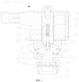
FIG. 1 is a schematic diagram of an assembly of an electromagnetic valve and a mounting base in an embodiment of the present invention. -
FIG. 2 is a schematic diagram of a longitudinal section ofFIG. 1 . -
FIG. 3 is a cross-sectional diagram of an electromagnetic valve in the present invention. -
FIG. 4 is a schematic diagram of a valve seat in the present invention. -
FIG. 5 is a schematic diagram of a magnetic conductive frame in an embodiment of the present invention. -
FIG. 6 is a schematic diagram of a magnetic conductive frame in an embodiment of the present invention. -
FIG. 7 is a schematic diagram of an electromagnetic valve assembly in an embodiment of the present invention. - In the figures, 100 represents an electromagnetic valve, 1 represents a valve seat, 11 represents a first cavity, 12 represents a clamping portion, 121 represents a clamping plane, 13 represents a connecting portion, 131 represents a first threaded portion, 14 represents an inlet flow channel, 15 represents an outlet flow channel, 16 represents a valve port, 2 represents a magnetic conductive frame, 21 represents a positioning member, 22 represents a bent portion, 23 represents a first through hole, 24 represents a connecting member, 3 represents an electromagnetic driving assembly, 31 represents a sleeve, 32 represents an electromagnetic coil, 33 represents a stator, 34 represents an actuator, 341 represents a third cavity, 35 represents a valve needle, 36 represents a first elastic member, 37 represents an elastic member of a valve needle, 4 represents a valve cover, 5 represents a mounting base, 52 represents a mounting portion, 6 represents a blocking assembly, 61 represents a blocking body, 62 represents a second elastic member, 63 represents a pilot valve port, and 200 represents an electromagnetic valve assembly.
- The technical solutions in the embodiments of the present invention are clearly and completely described in the following with reference to the accompanying drawings in the embodiments of the present invention. It is obvious that the described embodiments are only a part of the embodiments, but not all of the embodiments. All other embodiments obtained by those skilled in the art based on the embodiments of the present invention without making creative labor are the scope of the present invention.
- It should be noted that when an assembly is considered to be "disposed on" another assembly, it can be directly disposed to another assembly, or there can be a centered assembly. When an assembly is considered to be "set on" another assembly, it can be directly set on another assembly, or there can be a centered assembly at the same time. When an assembly is considered to be "fixed to" another assembly, it can be directly fixed to another assembly, or there can be a centered assembly at the same time.
- Unless otherwise defined, all technical and scientific terms used herein have the same meaning as a skilled person in the art would understand. The terminology used in the description of the present invention is for the purpose of describing particular embodiments and is not intended to limit the invention. The term "or/and" as used herein includes any and all combinations of one or more of the associated listed items.
- Referring to
FIG. 1 , the present invention provides anelectromagnetic valve 100, which is mounted on amounting base 5. Theelectromagnetic valve 100 is configured to control on/off of medium or a magnitude of medium flow in a pipeline. - Specifically, the
electromagnetic valve 100 includes a valve body, a magneticconductive frame 2, and anelectromagnetic driving assembly 3. The valve body at least includes avalve seat 1, the magneticconductive frame 2 is fixed to thevalve seat 1, and theelectromagnetic driving assembly 3 is mounted in the magneticconductive frame 2. The magneticconductive frame 2 is provided with apositioning member 21, after theelectromagnetic valve 100 is mounted on themounting base 5, thepositioning member 21 is capable of being connected to themounting base 5 so as to restrict theelectromagnetic driving assembly 3 from rotating relative to themounting base 5. Thus, it may rapidly realize fixation of theelectromagnetic driving assembly 3 and improve overall assembly efficiency. Meanwhile, it may be prevented that theelectromagnetic driving assembly 3 deviates in orientation in an applying process and even shifts relative to themounting base 5, and it may ensure stability of theelectromagnetic valve 100 in the applying process. - In an embodiment, referring to
FIG. 1 andFIG. 5 , thepositioning member 21 may include a pin of the magneticconductive frame 2 extending towards themounting base 5. During mounting, the orientation of theelectromagnetic driving assembly 3 and the magneticconductive frame 2 may be determined according to specific mounting requirements. By restricting the pin to themounting base 5, orientations of theelectromagnetic driving assembly 3 and the magneticconductive frame 2 may be rapidly positioned and fixed to prevent theelectromagnetic driving assembly 3 and the magneticconductive frame 2 from rotating or deflecting relative to themounting base 5. In this embodiment, a specific structure of the positioningmember 21 may be not limited to the above description. For example, it may also be a protruding structure set on the magneticconductive frame 2 or a snap structure that may cooperate with and be connected to the mountingbase 5. - In an embodiment, referring to
FIG. 1 andFIG. 5 , the pin may be L shaped. An end of a L-shaped pin may be connected to the magneticconductive frame 2, and another end may be connected to the mountingbase 5 to realize the positioning of the orientation of the magneticconductive frame 2. In other embodiments, a specific structural form of the pin is not limited to the shape of L, but may also be other shapes, such as a shape of C and the like. - In an embodiment, referring to
FIG. 6 and FIG. 7 , an end of the pin away from the magneticconductive frame 2 may be bent to define as abent portion 22, and thebent portion 22 is provided with a first throughhole 23. Theelectromagnetic valve 100 may further include a connectingmember 24, which may penetrate through the first throughhole 23 and be connected to the mountingbase 5. The connectingmember 24 may be a bolt or a dowel, etc. - Alternatively, the
bent portion 22 may abut against the mountingbase 5. When the magneticconductive frame 2 is assembled and mounted, thebent portion 22 of the pin may just abut against the mountingbase 5, and thebent portion 22 and the mountingbase 5 may cooperate with each other to reduce difficulty of assembly. When thebent portion 22 abuts against the mountingbase 5, the mountingbase 5 may play a certain supportive role for the magneticconductive frame 2, and the assembly may be more stable. In other embodiments, a gap may exist between thebent portion 22 and the mountingbase 5. - In an embodiment, referring to
FIG. 1 to FIG. 4 , thevalve seat 1 may further include a clampingportion 12, which is provided proximal to the magneticconductive frame 2, and a part of the clampingportion 12 may protrude from the mountingbase 5 along an axial direction of thevalve seat 1. The positioningmember 21 is provided at an end of the magneticconductive frame 2 proximal to thevalve seat 1, and the part of the clampingportion 12 protruding from the mountingbase 5 along the axial direction of thevalve seat 1 may have the same height as the positioningmember 21. The part of the clampingportion 12 protruding from the mountingbase 5 may have the same height as the positioningmember 21, so that the positioningmember 21 may be exactly in contact with the mountingbase 5 and is connected to the mountingbase 5 after the assembly is completed, and thevalve seat 1 may also abut against the magneticconductive frame 2, reducing a height of theelectromagnetic valve 100 and the mountingbase 5 after the assembly and decreasing occupied space. Heights of a plurality of members may be adapted to match each other, allowing the assembly of theelectromagnetic valve 100 and the mountingbase 5 rapider and more aesthetically pleasing. In other embodiments, the height of the clampingportion 12 and the height of the positioningmember 21 may be not limited, and the height of the clampingportion 12 may be not equal to the height of the positioningmember 21. - Alternatively, the clamping
portion 12 is provided with at least two clampingplanes 121, and an external mounting tool may cooperate with the clamping planes to realize a connection between thevalve seat 1 and the mountingbase 5 to be tightened, so as to improve the assembly efficiency. - Alternatively, referring to
FIG. 4 , a plurality of clampingplanes 121, such as six clampingplanes 121, are provided on the clampingportion 12 of thevalve seat 1, and the plurality of clampingplanes 121 are distributed equally circumferentially around thevalve seat 1. In other embodiments, the number of clampingplanes 121 may be not limited. - In an embodiment, alternatively, the positioning
member 21 and the magneticconductive frame 2 may be an integral construction, resulting in reducing assembly steps between the positioningmember 21 and the magneticconductive frame 2, and the integral construction may enable a connection between the positioningmember 21 and the magneticconductive frame 2 more stable. In other embodiments, the positioningmember 21 and the magneticconductive frame 2 may be split constructions. - The present invention further provides an
electromagnetic valve assembly 200. Referring toFIG. 1 andFIG. 7 , theelectromagnetic valve assembly 200 includes a mountingbase 5 and any one of the above electromagnetic valves, and the electromagnetic valve is mounted in the mountingbase 5. - In an embodiment, the mounting
base 5 is provided with a mountingportion 52 corresponding to the positioningmember 21, and the positioningmember 21 may cooperate with the mountingportion 52 to limit rotation of the magneticconductive frame 2. Specifically, referring toFIG. 1 andFIG. 5 , the mountingportion 52 may be a groove disposed on the mountingbase 5, and the pin may be inserted into the groove correspondingly to rapidly complete the positioning of the orientation of the magneticconductive frame 2 when assembling. In other embodiments, the number of the groove may be not limited. For example, a plurality of grooves may be disposed, and the pin may be inserted into a corresponding groove according to a desired orientation of the magneticconductive frame 2. Referring toFIG. 1 , the mountingportion 52 may also be a through hole disposed on the mountingbase 5, and an end of the connectingmember 24 may penetrate through the first throughhole 23 of thebent portion 22 and be inserted into the through hole of the mountingbase 5, realizing a limitation of the orientation of the magneticconductive frame 2. The connectingmember 24 may be a bolt or a dowel, etc. Alternatively, an end of the connectingmember 24 proximal to thebent portion 22 may abut against thebent portion 22, realizing an axial limitation of thebent portion 22 and preventing the positioningmember 21 from moving along an axial direction of thevalve seat 1 and back towards the mountingbase 5 and detaching from the mountingbase 5. - In an embodiment, the clamping
portion 12 and a connectingportion 13 may be sequentially provided along the axial direction of thevalve seat 1 top-down. An outer side wall of the connectingportion 13 may be provided with a first threadedportion 131, the corresponding mountingbase 5 may be provided with a second threaded portion, and the first threadedportion 131 may be connected to the second threaded portion to realize a rapid assembly of thevalve seat 1 and the mountingbase 5. - In an embodiment, referring to
FIG. 2 andFIG. 3 , the valve body may further include avalve cover 4, thevalve seat 1 is provided with afirst cavity 11, an outer side wall of thevalve cover 4 is sealingly connected to an inner wall side of thefirst cavity 11, and thevalve cover 4 may have no relative sliding with thevalve seat 1. The magneticconductive frame 2 may be mounted on thevalve seat 1 and thevalve cover 4 and a lower end surface of the magneticconductive frame 2 may abut against thevalve seat 1 and thevalve cover 4. - The
valve seat 1 is provided with aninlet flow channel 14 and anoutlet flow channel 15 which are connected to and in communication with avalve port 16 and thefirst cavity 11. Opening and closing of thevalve port 16 may control communication and closure between theinlet flow channel 14 and theoutlet flow channel 15. - In an embodiment, the electromagnetic valve may further include a blocking assembly 6, the
valve seat 1 is provided with avalve port 16, and the blocking assembly 6 is disposed in thevalve seat 1 and is capable of opening and closing thevalve port 16 when the blocking assembly 6 is driven by theelectromagnetic driving assembly 3. - In an embodiment, an end of the
valve cover 4 away from the magneticconductive frame 2 is provided with a second cavity configured for accommodating the blocking assembly 6, and an end of the blocking assembly 6 proximal to the magneticconductive frame 2 may be sealingly and slidingly connected to a cavity wall of the second cavity. - In an embodiment, the blocking assembly 6 may include a blocking
body 61 and a second elastic member 62, an end of the blockingbody 61 may be accommodated in the second cavity, and another end of the blockingbody 61 is configured for blocking thevalve port 16. An end of the second elastic member 62 may abut against an end of the blockingbody 61 proximal to the magneticconductive frame 2, and another end of the second elastic member 62 may abut against an end of thefirst cavity 11 away from the magneticconductive frame 2. The second elastic member 62 is configured to open the valve so that resilient recovery drives the blockingbody 61 to move towards the magneticconductive frame 2 for opening thevalve port 16. - In an embodiment, the
electromagnetic driving assembly 3 may include an electromagnetic unit and a valve needle unit. The electromagnetic unit may drive thevalve needle 35 to move back towards the blockingbody 61 to open the valve when the electromagnetic unit is energized. When the power is turned off, the blockingbody 61 may move towards thevalve port 16 until the blockingbody 61 seals against thevalve port 16 to close thevalve port 16. - Specifically, an end of the blocking
body 61 proximal to thevalve needle 35 is provided with a pilot valve port 63, thevalve needle 35 may be driven by the electromagnetic unit to open and close the pilot valve port 63. When the pilot valve port 63 is opened to relieve pressure, a pressure of a side of the blocking assembly 6 proximal to thevalve needle 35 may be less than a pressure of a side of the blocking assembly 6 proximal to thevalve port 16. When differential pressure force is sufficient, the blocking assembly 6 may move back towards thevalve port 16, so that the valve port is opened. In an embodiment, the electromagnetic unit may include anelectromagnetic coil 32, astator 33 that is stationary with respect to theelectromagnetic coil 32, and anactuator 34 that is movable along an axial direction of thevalve seat 1. Theelectromagnetic coil 32 may be sheathed outside thestator 33 and theactuator 34. A firstelastic member 36 is further provided between thestator 33 and theactuator 34, theactuator 34 is provided with athird cavity 341 penetrating through theactuator 34 along an axial direction, the firstelastic member 36 may be at least partially movable in thethird cavity 341, and the firstelastic member 36 may resiliently recover to drive the valve needle unit to move towards the blockingbody 61, so as to drive the blockingbody 61 to move towards thevalve port 16 to close thevalve port 16. Theelectromagnetic coil 32 may be fixed in the magneticconductive frame 2. - In an embodiment, the electromagnetic driving assembly may further include a
sleeve 31, and an end of thesleeve 31 proximal to thevalve seat 1 may extend out of the magneticconductive frame 2 and be fixedly connected to thevalve cover 4. Thestator 33 may be fixed to an end of thesleeve 31 away from thevalve seat 1, theactuator 34 may be movable inside thesleeve 31, and theelectromagnetic coil 32 may be sheathed outside thesleeve 31. - The valve needle unit may include a
valve needle 35 and an elastic member of thevalve needle 35. Thevalve needle 35 may be movable in thethird cavity 341, an end of the elastic member of thevalve needle 35 may abut against an end of thevalve needle 35 proximal to thestator 33, and another end of the elastic member of thevalve needle 35 may abut against an end of thethird cavity 341 proximal to thevalve seat 1. - A process of opening valve of the
electromagnetic valve 100 in the present invention may be as follows: theelectromagnetic coil 32 is powered on, theactuator 34 moves towards thestator 33, and theactuator 34 overcomes elastic force of the firstelastic member 36 and moves upward until the actuator 34 contacts thevalve needle 35 and drives thevalve needle 35 to move back towards thevalve seat 1. At this moment, theactuator 34 needs to overcome force of the firstelastic member 36 to move upward, a gap between the actuator 34 and thestator 33 is quite narrow, a suction force is much greater than that in initial stage of suction, theactuator 34 has a great kinetic energy, it is easy to realize opening valve, and a valve opening ability is much better than that of the conventional structure. Finally, theactuator 34 and thestator 33 are fully contacted, thevalve needle 35 continues to move upward to an upper limitation under an action of the elastic member of thevalve needle 35, a pressure of the pilot valve port 63 is relieved, an upper pressure of the blockingbody 61 is less than a lower pressure of the blockingbody 61, the blockingbody 61 moves upward to fit with thevalve cover 4, and thevalve port 16 is fully open. - When the valve is closed, the
electromagnetic coil 32 is powered off, theactuator 34 is not subject to a magnetic attraction of thestator 33, theactuator 34 drives thevalve needle 35 to move downward under an action of the elastic member of thevalve needle 35 to realize closing of thevalve port 16. - The technical features of the above-described embodiments may be combined in any combination. For the sake of brevity of description, all possible combinations of the technical features in the above embodiments are not described. However, as long as there is no contradiction between the combinations of these technical features, all should be considered as within the scope of this invention.
- The above-described embodiments are merely illustrative of several embodiments of the present invention, and the description thereof is relatively specific and detailed, but is not to be construed as limiting the scope of the invention. It should be noted that a number of variations and modifications may be made by those skilled in the art without departing from the spirit and scope of the invention. Therefore, the scope of the invention should be determined by the appended claims.
Claims (10)
- An electromagnetic valve, mounted on a mounting base, characterized in that the electromagnetic valve comprises:a valve body, at least comprising a valve seat, wherein the valve seat is mounted on the mounting base;a magnetic conductive frame fixed to the valve seat; andan electromagnetic driving assembly mounted in the magnetic conductive frame;wherein the magnetic conductive frame is provided with a positioning member, and the positioning member is capable of being connected to the mounting base so as to restrict the electromagnetic driving assembly from rotating relative to the mounting base.
- The electromagnetic valve of claim 1, wherein the positioning member comprises a pin located on the magnetic conductive frame extending towards the mounting base.
- The electromagnetic valve of claim 2, wherein the pin is in a shape of a L.
- The electromagnetic valve of claim 2, wherein an end of the pin away from the magnetic conductive frame is bent to define as a bent portion, and the bent portion is provided with a first through hole; and
the electromagnetic valve further comprises a connecting member, which penetrates through the first through hole and is connected to the mounting base. - The electromagnetic valve of claim 4, wherein the bent portion abuts against the mounting base.
- The electromagnetic valve of claim 1 or claim 5, wherein the valve seat further comprises a clamping portion, which is provided proximal to the magnetic conductive frame, and a part of the clamping portion protrudes from the mounting base along an axial direction of the valve seat; and
the positioning member is provided at an end of the magnetic conductive frame proximal to the valve seat, and the part of the clamping portion protruding from the mounting base along the axial direction of the valve seat has the same height as the positioning member. - The electromagnetic valve of claim 1, wherein the positioning member and the magnetic conductive frame are an integral structure.
- The electromagnetic valve of claim 1, further comprising a blocking assembly, the valve seat is provided with a valve port, and the blocking assembly is disposed in the valve seat and is capable of opening and sealing the valve port when the blocking assembly is driven by the electromagnetic driving assembly.
- An electromagnetic valve assembly, characterized by comprising a mounting base and the electromagnetic valve of any one of claims 1 to 8, wherein at least a part of the electromagnetic valve is mounted in the mounting base.
- The electromagnetic valve assembly of claim 9, wherein the mounting base is provided with a mounting portion corresponding to the positioning member, and the positioning member cooperates with the mounting portion to limit rotation of the magnetic conductive frame.
Applications Claiming Priority (2)
| Application Number | Priority Date | Filing Date | Title |
|---|---|---|---|
| CN202120591592.4U CN217381870U (en) | 2021-03-23 | 2021-03-23 | Solenoid valve and solenoid valve subassembly |
| PCT/CN2022/074849 WO2022199253A1 (en) | 2021-03-23 | 2022-01-28 | Electromagnetic valve and electromagnetic valve assembly |
Publications (2)
| Publication Number | Publication Date |
|---|---|
| EP4311966A1 true EP4311966A1 (en) | 2024-01-31 |
| EP4311966A4 EP4311966A4 (en) | 2024-09-04 |
Family
ID=83083593
Family Applications (1)
| Application Number | Title | Priority Date | Filing Date |
|---|---|---|---|
| EP22773915.8A Pending EP4311966A4 (en) | 2021-03-23 | 2022-01-28 | Electromagnetic valve and electromagnetic valve assembly |
Country Status (6)
| Country | Link |
|---|---|
| US (1) | US12338910B2 (en) |
| EP (1) | EP4311966A4 (en) |
| JP (1) | JP7649383B2 (en) |
| KR (1) | KR102814230B1 (en) |
| CN (1) | CN217381870U (en) |
| WO (1) | WO2022199253A1 (en) |
Cited By (1)
| Publication number | Priority date | Publication date | Assignee | Title |
|---|---|---|---|---|
| EP4534879A4 (en) * | 2022-06-02 | 2026-05-13 | Fujikoki Corp | ELECTRICALLY OPERATED VALVE |
Family Cites Families (22)
| Publication number | Priority date | Publication date | Assignee | Title |
|---|---|---|---|---|
| US3665960A (en) * | 1970-09-11 | 1972-05-30 | Whirlpool Co | Audible indicator for solenoid valve |
| US4540154A (en) * | 1982-06-28 | 1985-09-10 | Imperial Clevite Inc. | Solenoid valve |
| US5299775A (en) * | 1991-10-15 | 1994-04-05 | Kolze, Inc. | Flow modulating control valve assembly |
| JP3345306B2 (en) * | 1997-07-23 | 2002-11-18 | 三菱電機株式会社 | Pressure detector |
| US6029703A (en) * | 1998-12-18 | 2000-02-29 | Borg-Warner Automotive, Inc. | Pressure solenoid control valve with flux shunt |
| JP4110894B2 (en) * | 2002-09-06 | 2008-07-02 | Nok株式会社 | Solenoid valve |
| DE10359363A1 (en) * | 2003-12-18 | 2005-07-14 | Ina-Schaeffler Kg | Electromagnetic hydraulic valve, in particular 3/2-way switching valve for controlling a variable valve train of an internal combustion engine |
| DE102005034939A1 (en) * | 2005-07-27 | 2007-02-01 | Schaeffler Kg | Electromagnetic adjustment unit for hydraulic directional control valve, has press-fit structure which comprises material masses formed on magnet yoke tubular region extending radially outwards over edges of base opening of housing |
| US7938383B2 (en) * | 2007-08-08 | 2011-05-10 | Deltrol Controls | Solenoid mounting arrangement for liquid dispensing valve |
| JP6231113B2 (en) * | 2013-09-10 | 2017-11-15 | 日立オートモティブシステムズ株式会社 | solenoid valve |
| DE102014113540B3 (en) * | 2014-09-19 | 2016-02-04 | Pierburg Gmbh | Recirculation valve for a compressor of an internal combustion engine |
| CN205938095U (en) * | 2016-06-29 | 2017-02-08 | 盾安环境技术有限公司 | Normally open electromagnetic valve |
| CN206708508U (en) * | 2017-04-24 | 2017-12-05 | 浙江科博电器有限公司 | Miniature waterway electromagnetic valve |
| CN206708490U (en) * | 2017-04-24 | 2017-12-05 | 浙江科博电器有限公司 | The miniature electromagnetic valve that a kind of intake-outlet homonymy is set |
| CN206943546U (en) * | 2017-04-24 | 2018-01-30 | 浙江盾安机械有限公司 | A kind of magnetic valve |
| US10288190B2 (en) * | 2017-06-26 | 2019-05-14 | Schaeffler Technologies AG & Co. KG | Interlocking solenoid valve assembly and method |
| CN110242784A (en) * | 2018-03-09 | 2019-09-17 | 盾安汽车热管理科技有限公司 | A kind of combination solenoid valve and automotive thermal tube manage system |
| CN110792786B (en) * | 2018-08-01 | 2021-09-28 | 盾安环境技术有限公司 | Electromagnetic valve |
| KR102177298B1 (en) * | 2019-05-31 | 2020-11-10 | 주식회사 엠씨엠 | Water purifier valve and water purifier having the same |
| EP3800650A1 (en) * | 2019-10-01 | 2021-04-07 | HUSCO Automotive Holdings LLC | Dual-flanged unitary pole piece and electromagnetic actuator including the dual-flanged unitary pole piece |
| CN111963695B (en) * | 2020-07-28 | 2022-01-25 | 东风汽车集团有限公司 | Automobile-used electronic expansion valve and vehicle of low wear structure |
| CN212718017U (en) * | 2020-08-04 | 2021-03-16 | 龙泉市惠丰进出口有限公司 | Electromagnetic valve |
-
2021
- 2021-03-23 CN CN202120591592.4U patent/CN217381870U/en active Active
-
2022
- 2022-01-28 WO PCT/CN2022/074849 patent/WO2022199253A1/en not_active Ceased
- 2022-01-28 EP EP22773915.8A patent/EP4311966A4/en active Pending
- 2022-01-28 KR KR1020237036042A patent/KR102814230B1/en active Active
- 2022-01-28 JP JP2023550626A patent/JP7649383B2/en active Active
-
2023
- 2023-09-18 US US18/369,793 patent/US12338910B2/en active Active
Cited By (1)
| Publication number | Priority date | Publication date | Assignee | Title |
|---|---|---|---|---|
| EP4534879A4 (en) * | 2022-06-02 | 2026-05-13 | Fujikoki Corp | ELECTRICALLY OPERATED VALVE |
Also Published As
| Publication number | Publication date |
|---|---|
| US20240003460A1 (en) | 2024-01-04 |
| JP2024510391A (en) | 2024-03-07 |
| KR102814230B1 (en) | 2025-05-29 |
| JP7649383B2 (en) | 2025-03-19 |
| US12338910B2 (en) | 2025-06-24 |
| EP4311966A4 (en) | 2024-09-04 |
| WO2022199253A1 (en) | 2022-09-29 |
| CN217381870U (en) | 2022-09-06 |
| KR20230159555A (en) | 2023-11-21 |
Similar Documents
| Publication | Publication Date | Title |
|---|---|---|
| EP4311965A1 (en) | Electromagnetic valve and electromagnetic valve assembly | |
| CN217177431U (en) | Electric combined valve | |
| US12338910B2 (en) | Electromagnetic valve and electromagnetic valve assembly | |
| KR20010082103A (en) | Four way type switching valve | |
| JP2000227165A (en) | Electric control valve | |
| EP2267348A1 (en) | A normally open solenoid valve and an assembling method thereof | |
| US11193596B2 (en) | Electric valve and manufacturing method therefor | |
| CN110792786B (en) | Electromagnetic valve | |
| CN222992162U (en) | Solenoid valve and air conditioning system | |
| JP2000320711A (en) | Electric control valve | |
| CN212718015U (en) | Electromagnetic valve | |
| CN212318842U (en) | Normally open solenoid valve | |
| EP4628764A1 (en) | Control valve | |
| JP2009275895A (en) | Flow control valve | |
| WO2021254419A1 (en) | Solenoid valve | |
| CN217207747U (en) | Electromagnetic valve and gas equipment | |
| CN214699420U (en) | Small-sized electric valve | |
| CN115031050B (en) | A solenoid valve | |
| CN219493216U (en) | Solenoid valve, vehicle body posture control device and vehicle | |
| CN210318567U (en) | Proportional valve and proportional valve assembly | |
| CN223019444U (en) | Valve and fluid control assembly | |
| CN223854906U (en) | Valve and combined four-way valve | |
| CN223868647U (en) | A solenoid valve | |
| CN217328485U (en) | Solenoid valve, refrigeration plant and car | |
| CN219712482U (en) | Eccentric wheel valve opening and closing structure |
Legal Events
| Date | Code | Title | Description |
|---|---|---|---|
| STAA | Information on the status of an ep patent application or granted ep patent |
Free format text: STATUS: THE INTERNATIONAL PUBLICATION HAS BEEN MADE |
|
| PUAI | Public reference made under article 153(3) epc to a published international application that has entered the european phase |
Free format text: ORIGINAL CODE: 0009012 |
|
| STAA | Information on the status of an ep patent application or granted ep patent |
Free format text: STATUS: REQUEST FOR EXAMINATION WAS MADE |
|
| 17P | Request for examination filed |
Effective date: 20230925 |
|
| AK | Designated contracting states |
Kind code of ref document: A1 Designated state(s): AL AT BE BG CH CY CZ DE DK EE ES FI FR GB GR HR HU IE IS IT LI LT LU LV MC MK MT NL NO PL PT RO RS SE SI SK SM TR |
|
| DAV | Request for validation of the european patent (deleted) | ||
| DAX | Request for extension of the european patent (deleted) | ||
| A4 | Supplementary search report drawn up and despatched |
Effective date: 20240806 |
|
| RIC1 | Information provided on ipc code assigned before grant |
Ipc: F16K 27/02 20060101ALI20240731BHEP Ipc: F16K 31/40 20060101ALI20240731BHEP Ipc: F16K 31/06 20060101AFI20240731BHEP |