EP4311951A1 - Bearing apparatus and laser apparatus comprising bearing apparatus - Google Patents
Bearing apparatus and laser apparatus comprising bearing apparatus Download PDFInfo
- Publication number
- EP4311951A1 EP4311951A1 EP23187952.9A EP23187952A EP4311951A1 EP 4311951 A1 EP4311951 A1 EP 4311951A1 EP 23187952 A EP23187952 A EP 23187952A EP 4311951 A1 EP4311951 A1 EP 4311951A1
- Authority
- EP
- European Patent Office
- Prior art keywords
- bearing
- outer ring
- inner ring
- touchdown
- laser
- Prior art date
- Legal status (The legal status is an assumption and is not a legal conclusion. Google has not performed a legal analysis and makes no representation as to the accuracy of the status listed.)
- Granted
Links
Images



Classifications
-
- F—MECHANICAL ENGINEERING; LIGHTING; HEATING; WEAPONS; BLASTING
- F16—ENGINEERING ELEMENTS AND UNITS; GENERAL MEASURES FOR PRODUCING AND MAINTAINING EFFECTIVE FUNCTIONING OF MACHINES OR INSTALLATIONS; THERMAL INSULATION IN GENERAL
- F16C—SHAFTS; FLEXIBLE SHAFTS; ELEMENTS OR CRANKSHAFT MECHANISMS; ROTARY BODIES OTHER THAN GEARING ELEMENTS; BEARINGS
- F16C32/00—Bearings not otherwise provided for
- F16C32/04—Bearings not otherwise provided for using magnetic or electric supporting means
- F16C32/0406—Magnetic bearings
- F16C32/044—Active magnetic bearings
- F16C32/0442—Active magnetic bearings with devices affected by abnormal, undesired or non-standard conditions such as shock-load, power outage, start-up or touchdown
-
- F—MECHANICAL ENGINEERING; LIGHTING; HEATING; WEAPONS; BLASTING
- F16—ENGINEERING ELEMENTS AND UNITS; GENERAL MEASURES FOR PRODUCING AND MAINTAINING EFFECTIVE FUNCTIONING OF MACHINES OR INSTALLATIONS; THERMAL INSULATION IN GENERAL
- F16C—SHAFTS; FLEXIBLE SHAFTS; ELEMENTS OR CRANKSHAFT MECHANISMS; ROTARY BODIES OTHER THAN GEARING ELEMENTS; BEARINGS
- F16C32/00—Bearings not otherwise provided for
- F16C32/04—Bearings not otherwise provided for using magnetic or electric supporting means
- F16C32/0406—Magnetic bearings
- F16C32/044—Active magnetic bearings
- F16C32/047—Details of housings; Mounting of active magnetic bearings
-
- C—CHEMISTRY; METALLURGY
- C22—METALLURGY; FERROUS OR NON-FERROUS ALLOYS; TREATMENT OF ALLOYS OR NON-FERROUS METALS
- C22C—ALLOYS
- C22C19/00—Alloys based on nickel or cobalt
- C22C19/03—Alloys based on nickel or cobalt based on nickel
- C22C19/05—Alloys based on nickel or cobalt based on nickel with chromium
-
- F—MECHANICAL ENGINEERING; LIGHTING; HEATING; WEAPONS; BLASTING
- F16—ENGINEERING ELEMENTS AND UNITS; GENERAL MEASURES FOR PRODUCING AND MAINTAINING EFFECTIVE FUNCTIONING OF MACHINES OR INSTALLATIONS; THERMAL INSULATION IN GENERAL
- F16C—SHAFTS; FLEXIBLE SHAFTS; ELEMENTS OR CRANKSHAFT MECHANISMS; ROTARY BODIES OTHER THAN GEARING ELEMENTS; BEARINGS
- F16C19/00—Bearings with rolling contact, for exclusively rotary movement
- F16C19/02—Bearings with rolling contact, for exclusively rotary movement with bearing balls essentially of the same size in one or more circular rows
- F16C19/04—Bearings with rolling contact, for exclusively rotary movement with bearing balls essentially of the same size in one or more circular rows for radial load mainly
-
- F—MECHANICAL ENGINEERING; LIGHTING; HEATING; WEAPONS; BLASTING
- F16—ENGINEERING ELEMENTS AND UNITS; GENERAL MEASURES FOR PRODUCING AND MAINTAINING EFFECTIVE FUNCTIONING OF MACHINES OR INSTALLATIONS; THERMAL INSULATION IN GENERAL
- F16C—SHAFTS; FLEXIBLE SHAFTS; ELEMENTS OR CRANKSHAFT MECHANISMS; ROTARY BODIES OTHER THAN GEARING ELEMENTS; BEARINGS
- F16C19/00—Bearings with rolling contact, for exclusively rotary movement
- F16C19/50—Other types of ball or roller bearings
-
- F—MECHANICAL ENGINEERING; LIGHTING; HEATING; WEAPONS; BLASTING
- F16—ENGINEERING ELEMENTS AND UNITS; GENERAL MEASURES FOR PRODUCING AND MAINTAINING EFFECTIVE FUNCTIONING OF MACHINES OR INSTALLATIONS; THERMAL INSULATION IN GENERAL
- F16C—SHAFTS; FLEXIBLE SHAFTS; ELEMENTS OR CRANKSHAFT MECHANISMS; ROTARY BODIES OTHER THAN GEARING ELEMENTS; BEARINGS
- F16C32/00—Bearings not otherwise provided for
- F16C32/04—Bearings not otherwise provided for using magnetic or electric supporting means
- F16C32/0402—Bearings not otherwise provided for using magnetic or electric supporting means combined with other supporting means, e.g. hybrid bearings with both magnetic and fluid supporting means
-
- F—MECHANICAL ENGINEERING; LIGHTING; HEATING; WEAPONS; BLASTING
- F16—ENGINEERING ELEMENTS AND UNITS; GENERAL MEASURES FOR PRODUCING AND MAINTAINING EFFECTIVE FUNCTIONING OF MACHINES OR INSTALLATIONS; THERMAL INSULATION IN GENERAL
- F16C—SHAFTS; FLEXIBLE SHAFTS; ELEMENTS OR CRANKSHAFT MECHANISMS; ROTARY BODIES OTHER THAN GEARING ELEMENTS; BEARINGS
- F16C32/00—Bearings not otherwise provided for
- F16C32/04—Bearings not otherwise provided for using magnetic or electric supporting means
- F16C32/0406—Magnetic bearings
-
- F—MECHANICAL ENGINEERING; LIGHTING; HEATING; WEAPONS; BLASTING
- F16—ENGINEERING ELEMENTS AND UNITS; GENERAL MEASURES FOR PRODUCING AND MAINTAINING EFFECTIVE FUNCTIONING OF MACHINES OR INSTALLATIONS; THERMAL INSULATION IN GENERAL
- F16C—SHAFTS; FLEXIBLE SHAFTS; ELEMENTS OR CRANKSHAFT MECHANISMS; ROTARY BODIES OTHER THAN GEARING ELEMENTS; BEARINGS
- F16C33/00—Parts of bearings; Special methods for making bearings or parts thereof
- F16C33/30—Parts of ball or roller bearings
- F16C33/306—Means to synchronise movements
-
- F—MECHANICAL ENGINEERING; LIGHTING; HEATING; WEAPONS; BLASTING
- F16—ENGINEERING ELEMENTS AND UNITS; GENERAL MEASURES FOR PRODUCING AND MAINTAINING EFFECTIVE FUNCTIONING OF MACHINES OR INSTALLATIONS; THERMAL INSULATION IN GENERAL
- F16C—SHAFTS; FLEXIBLE SHAFTS; ELEMENTS OR CRANKSHAFT MECHANISMS; ROTARY BODIES OTHER THAN GEARING ELEMENTS; BEARINGS
- F16C33/00—Parts of bearings; Special methods for making bearings or parts thereof
- F16C33/30—Parts of ball or roller bearings
- F16C33/32—Balls
-
- F—MECHANICAL ENGINEERING; LIGHTING; HEATING; WEAPONS; BLASTING
- F16—ENGINEERING ELEMENTS AND UNITS; GENERAL MEASURES FOR PRODUCING AND MAINTAINING EFFECTIVE FUNCTIONING OF MACHINES OR INSTALLATIONS; THERMAL INSULATION IN GENERAL
- F16C—SHAFTS; FLEXIBLE SHAFTS; ELEMENTS OR CRANKSHAFT MECHANISMS; ROTARY BODIES OTHER THAN GEARING ELEMENTS; BEARINGS
- F16C33/00—Parts of bearings; Special methods for making bearings or parts thereof
- F16C33/30—Parts of ball or roller bearings
- F16C33/58—Raceways; Race rings
- F16C33/62—Selection of substances
-
- F—MECHANICAL ENGINEERING; LIGHTING; HEATING; WEAPONS; BLASTING
- F16—ENGINEERING ELEMENTS AND UNITS; GENERAL MEASURES FOR PRODUCING AND MAINTAINING EFFECTIVE FUNCTIONING OF MACHINES OR INSTALLATIONS; THERMAL INSULATION IN GENERAL
- F16C—SHAFTS; FLEXIBLE SHAFTS; ELEMENTS OR CRANKSHAFT MECHANISMS; ROTARY BODIES OTHER THAN GEARING ELEMENTS; BEARINGS
- F16C39/00—Relieving load on bearings
- F16C39/02—Relieving load on bearings using mechanical means
-
- H—ELECTRICITY
- H01—ELECTRIC ELEMENTS
- H01S—DEVICES USING THE PROCESS OF LIGHT AMPLIFICATION BY STIMULATED EMISSION OF RADIATION [LASER] TO AMPLIFY OR GENERATE LIGHT; DEVICES USING STIMULATED EMISSION OF ELECTROMAGNETIC RADIATION IN WAVE RANGES OTHER THAN OPTICAL
- H01S3/00—Lasers, i.e. devices using stimulated emission of electromagnetic radiation in the infrared, visible or ultraviolet wave range
- H01S3/02—Constructional details
-
- H—ELECTRICITY
- H01—ELECTRIC ELEMENTS
- H01S—DEVICES USING THE PROCESS OF LIGHT AMPLIFICATION BY STIMULATED EMISSION OF RADIATION [LASER] TO AMPLIFY OR GENERATE LIGHT; DEVICES USING STIMULATED EMISSION OF ELECTROMAGNETIC RADIATION IN WAVE RANGES OTHER THAN OPTICAL
- H01S3/00—Lasers, i.e. devices using stimulated emission of electromagnetic radiation in the infrared, visible or ultraviolet wave range
- H01S3/02—Constructional details
- H01S3/03—Constructional details of gas laser discharge tubes
- H01S3/034—Optical devices within, or forming part of, the tube, e.g. windows, mirrors
-
- H—ELECTRICITY
- H01—ELECTRIC ELEMENTS
- H01S—DEVICES USING THE PROCESS OF LIGHT AMPLIFICATION BY STIMULATED EMISSION OF RADIATION [LASER] TO AMPLIFY OR GENERATE LIGHT; DEVICES USING STIMULATED EMISSION OF ELECTROMAGNETIC RADIATION IN WAVE RANGES OTHER THAN OPTICAL
- H01S3/00—Lasers, i.e. devices using stimulated emission of electromagnetic radiation in the infrared, visible or ultraviolet wave range
- H01S3/02—Constructional details
- H01S3/03—Constructional details of gas laser discharge tubes
- H01S3/036—Means for obtaining or maintaining the desired gas pressure within the tube, e.g. by gettering, replenishing; Means for circulating the gas, e.g. for equalising the pressure within the tube
-
- H—ELECTRICITY
- H02—GENERATION; CONVERSION OR DISTRIBUTION OF ELECTRIC POWER
- H02K—DYNAMO-ELECTRIC MACHINES
- H02K5/00—Casings; Enclosures; Supports
- H02K5/04—Casings or enclosures characterised by the shape, form or construction thereof
- H02K5/16—Means for supporting bearings, e.g. insulating supports or means for fitting bearings in the bearing-shields
-
- F—MECHANICAL ENGINEERING; LIGHTING; HEATING; WEAPONS; BLASTING
- F16—ENGINEERING ELEMENTS AND UNITS; GENERAL MEASURES FOR PRODUCING AND MAINTAINING EFFECTIVE FUNCTIONING OF MACHINES OR INSTALLATIONS; THERMAL INSULATION IN GENERAL
- F16C—SHAFTS; FLEXIBLE SHAFTS; ELEMENTS OR CRANKSHAFT MECHANISMS; ROTARY BODIES OTHER THAN GEARING ELEMENTS; BEARINGS
- F16C19/00—Bearings with rolling contact, for exclusively rotary movement
- F16C19/02—Bearings with rolling contact, for exclusively rotary movement with bearing balls essentially of the same size in one or more circular rows
- F16C19/04—Bearings with rolling contact, for exclusively rotary movement with bearing balls essentially of the same size in one or more circular rows for radial load mainly
- F16C19/06—Bearings with rolling contact, for exclusively rotary movement with bearing balls essentially of the same size in one or more circular rows for radial load mainly with a single row or balls
-
- F—MECHANICAL ENGINEERING; LIGHTING; HEATING; WEAPONS; BLASTING
- F16—ENGINEERING ELEMENTS AND UNITS; GENERAL MEASURES FOR PRODUCING AND MAINTAINING EFFECTIVE FUNCTIONING OF MACHINES OR INSTALLATIONS; THERMAL INSULATION IN GENERAL
- F16C—SHAFTS; FLEXIBLE SHAFTS; ELEMENTS OR CRANKSHAFT MECHANISMS; ROTARY BODIES OTHER THAN GEARING ELEMENTS; BEARINGS
- F16C2204/00—Metallic materials; Alloys
- F16C2204/52—Alloys based on nickel, e.g. Inconel
-
- F—MECHANICAL ENGINEERING; LIGHTING; HEATING; WEAPONS; BLASTING
- F16—ENGINEERING ELEMENTS AND UNITS; GENERAL MEASURES FOR PRODUCING AND MAINTAINING EFFECTIVE FUNCTIONING OF MACHINES OR INSTALLATIONS; THERMAL INSULATION IN GENERAL
- F16C—SHAFTS; FLEXIBLE SHAFTS; ELEMENTS OR CRANKSHAFT MECHANISMS; ROTARY BODIES OTHER THAN GEARING ELEMENTS; BEARINGS
- F16C2223/00—Surface treatments; Hardening; Coating
- F16C2223/30—Coating surfaces
-
- F—MECHANICAL ENGINEERING; LIGHTING; HEATING; WEAPONS; BLASTING
- F16—ENGINEERING ELEMENTS AND UNITS; GENERAL MEASURES FOR PRODUCING AND MAINTAINING EFFECTIVE FUNCTIONING OF MACHINES OR INSTALLATIONS; THERMAL INSULATION IN GENERAL
- F16C—SHAFTS; FLEXIBLE SHAFTS; ELEMENTS OR CRANKSHAFT MECHANISMS; ROTARY BODIES OTHER THAN GEARING ELEMENTS; BEARINGS
- F16C2223/00—Surface treatments; Hardening; Coating
- F16C2223/30—Coating surfaces
- F16C2223/60—Coating surfaces by vapour deposition, e.g. PVD, CVD
-
- F—MECHANICAL ENGINEERING; LIGHTING; HEATING; WEAPONS; BLASTING
- F16—ENGINEERING ELEMENTS AND UNITS; GENERAL MEASURES FOR PRODUCING AND MAINTAINING EFFECTIVE FUNCTIONING OF MACHINES OR INSTALLATIONS; THERMAL INSULATION IN GENERAL
- F16C—SHAFTS; FLEXIBLE SHAFTS; ELEMENTS OR CRANKSHAFT MECHANISMS; ROTARY BODIES OTHER THAN GEARING ELEMENTS; BEARINGS
- F16C2223/00—Surface treatments; Hardening; Coating
- F16C2223/30—Coating surfaces
- F16C2223/70—Coating surfaces by electroplating or electrolytic coating, e.g. anodising, galvanising
-
- F—MECHANICAL ENGINEERING; LIGHTING; HEATING; WEAPONS; BLASTING
- F16—ENGINEERING ELEMENTS AND UNITS; GENERAL MEASURES FOR PRODUCING AND MAINTAINING EFFECTIVE FUNCTIONING OF MACHINES OR INSTALLATIONS; THERMAL INSULATION IN GENERAL
- F16C—SHAFTS; FLEXIBLE SHAFTS; ELEMENTS OR CRANKSHAFT MECHANISMS; ROTARY BODIES OTHER THAN GEARING ELEMENTS; BEARINGS
- F16C2300/00—Application independent of particular apparatuses
- F16C2300/40—Application independent of particular apparatuses related to environment, i.e. operating conditions
- F16C2300/42—Application independent of particular apparatuses related to environment, i.e. operating conditions corrosive, i.e. with aggressive media or harsh conditions
-
- F—MECHANICAL ENGINEERING; LIGHTING; HEATING; WEAPONS; BLASTING
- F16—ENGINEERING ELEMENTS AND UNITS; GENERAL MEASURES FOR PRODUCING AND MAINTAINING EFFECTIVE FUNCTIONING OF MACHINES OR INSTALLATIONS; THERMAL INSULATION IN GENERAL
- F16C—SHAFTS; FLEXIBLE SHAFTS; ELEMENTS OR CRANKSHAFT MECHANISMS; ROTARY BODIES OTHER THAN GEARING ELEMENTS; BEARINGS
- F16C2380/00—Electrical apparatus
-
- H—ELECTRICITY
- H01—ELECTRIC ELEMENTS
- H01S—DEVICES USING THE PROCESS OF LIGHT AMPLIFICATION BY STIMULATED EMISSION OF RADIATION [LASER] TO AMPLIFY OR GENERATE LIGHT; DEVICES USING STIMULATED EMISSION OF ELECTROMAGNETIC RADIATION IN WAVE RANGES OTHER THAN OPTICAL
- H01S3/00—Lasers, i.e. devices using stimulated emission of electromagnetic radiation in the infrared, visible or ultraviolet wave range
- H01S3/14—Lasers, i.e. devices using stimulated emission of electromagnetic radiation in the infrared, visible or ultraviolet wave range characterised by the material used as the active medium
- H01S3/22—Gases
- H01S3/223—Gases the active gas being polyatomic, i.e. containing two or more atoms
- H01S3/225—Gases the active gas being polyatomic, i.e. containing two or more atoms comprising an excimer or exciplex
Definitions
- the present invention relates to a bearing apparatus comprising a magnetic bearing and a touchdown bearing, more specifically, a bearing apparatus used in a fluorine gas environment. Further, the present invention relates to a laser apparatus comprising a bearing apparatus such as that explained above.
- Patent Literatures 1, 2, and 3 discloses a technique to prevent, in an excimer laser apparatus including a fluorine gas in a chamber thereof, corrosion due to the fluorine gas by coating a surface of a touchdown bearing, which holds a cross-flow fan, by a thin film comprising nickel, chromium nitride, or the like.
- an object of the invention is to provide a bearing apparatus which is superior in corrosion resistance against a fluorine gas, and superior in dimensional accuracy and durability. Further, an object of the present invention is to provide a laser apparatus comprising a bearing apparatus such as that explained above.
- a bearing apparatus which is used in an environment wherein a fluorine gas exists
- the bearing apparatus comprises: a magnetic bearing comprising a magnetic member and an electromagnetic coil; and a touchdown bearing for protecting the magnetic bearing, wherein the touchdown bearing comprises an inner ring, an outer ring, and plural rolling members (balls, rollers, runners, or the like) arranged between the inner ring and the outer ring, wherein the inner ring and the outer ring in the touchdown bearing are constructed by using a NiCrAl alloy.
- Mode 2 comprises the bearing apparatus of Mode 1, wherein the plural rolling members are constructed by using a NiCrAl alloy, additionally.
- Mode 3 comprises the bearing apparatus of Mode 1, wherein the plural rolling members are constructed by using ceramic material, additionally.
- Mode 4 comprises the bearing apparatus of any one of Modes 1-3, wherein the content of Ni in the NiCrAl alloy is equal to or greater than 50 weight percent.
- Mode 5 comprises the bearing apparatus of any one of Modes 1-4, wherein the content of Cr in the NiCrAl alloy is equal to or greater than 30 weight percent.
- Mode 6 comprises the bearing apparatus of any one of Modes 1-5, wherein the content of Al in the NiCrAl alloy is equal to or greater than 3 weight percent.
- a laser apparatus comprising: a chamber in which a laser gas including a fluorine gas is enclosed, wherein the chamber comprises a fan for circulating the laser gas, a pair of discharge electrodes for making the laser gas discharge, and windows arranged to allow laser light to pass through them; and a bearing apparatus constructed to support the fan, wherein the bearing apparatus comprises a magnetic bearing comprising a magnetic member and an electromagnetic coil, and a touchdown bearing for protecting the magnetic bearing, wherein the touchdown bearing comprises an inner ring, an outer ring, and plural rolling members arranged between the inner ring and the outer ring, wherein the inner ring and the outer ring in the touchdown bearing are constructed by using a NiCrAl alloy.
- Mode 8 comprises the laser apparatus of Mode 7, wherein the plural rolling members are constructed by using a NiCrAl alloy, additionally.
- Mode 9 comprises the laser apparatus of Mode 7, wherein the plural rolling members are constructed by using ceramic material, additionally.
- Mode 10 comprises the laser apparatus of any one of Modes 7-9, wherein the content of Ni in the NiCrAl alloy is equal to or greater than 50 weight percent.
- Mode 11 comprises the laser apparatus of any one of Modes 7-10, wherein the content of Cr in the NiCrAl alloy is equal to or greater than 30 weight percent.
- Mode 12 comprises the laser apparatus of any one of Modes 7-11, wherein the content of Al in the NiCrAl alloy is equal to or greater than 3 weight percent.
- a laser apparatus comprising: a chamber in which a laser gas including a fluorine gas is enclosed, wherein the chamber comprises a fan for circulating the laser gas, a pair of discharge electrodes for making the laser gas discharge, and windows arranged to allow laser light to pass through them; and a bearing apparatus constructed to support the fan, wherein the bearing apparatus comprises a magnetic bearing comprising a magnetic member and an electromagnetic coil, and a touchdown bearing for protecting the magnetic bearing, wherein the touchdown bearing comprises an inner ring, an outer ring, and plural rolling members arranged between the inner ring and the outer ring, wherein the inner ring and the outer ring in the touchdown bearing are constructed by using a NiCrAl alloy, and the inner ring and the outer ring are plated by Ni or coated by ceramic material.
- Mode 14 comprises the laser apparatus of Mode 13, wherein surfaces other than rolling contact surfaces of the inner ring and the outer ring are plated by Ni or coated by ceramic material.
- Mode 15 comprises the laser apparatus of Mode 14, wherein surfaces which are perpendicular to the axis direction of the touchdown bearing and positioned on the side close to the chamber, among the surfaces of the inner ring and the outer ring, only are plated by Ni or coated by ceramic material.
- a laser apparatus comprising: a chamber in which a laser gas including a fluorine gas is enclosed, wherein the chamber comprises a fan for circulating the laser gas, a pair of discharge electrodes for making the laser gas discharge, and windows arranged to allow laser light to pass through them; and a bearing apparatus constructed to support the fan, wherein the bearing apparatus comprises a magnetic bearing comprising a magnetic member and an electromagnetic coil, and a touchdown bearing for protecting the magnetic bearing, wherein the touchdown bearing comprises an inner ring, an outer ring, and plural rolling members arranged between the inner ring and the outer ring, wherein the inner ring and the outer ring in the touchdown bearing are constructed by using a NiCrAl alloy, and surfaces which are perpendicular to the axis direction of the touchdown bearing and positioned on the side close to the chamber, among the surfaces of the inner ring and the outer ring, are plated by Ni or coated by ceramic material.
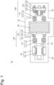
- Fig. 1 is a configuration diagram of a gas laser apparatus in which a bearing apparatus according to an embodiment of the present invention is adopted.
- a bearing apparatus 100 can be incorporated in an excimer laser apparatus 10, for example.
- the excimer laser apparatus 10 may be, for example, an ArF (argon/fluorine) excimer laser, KrF (krypton/fluorine) excimer laser, a XeCl (xenon/chlorine) excimer laser, or a XeF (xenon/fluorine) excimer laser.
- the excimer laser apparatus 10 comprises a chamber 20, a cross-flow fan 30, a rotating shaft 40, a motor 50, and the bearing apparatuses 100.
- the excimer laser apparatus 10 further comprises a discharge electrode, a laser resonator, and so on which are not shown in the figure.
- a mixed gas comprising a rare gas such as an Ar (argon) gas or the like and a halogen gas such as a F 2 (fluorine) gas is enclosed in the chamber 20.
- the cross-flow fan 30 is arranged in the chamber 20, and used for circulating the mixed gas in the chamber 20.
- the motor 50 rotates the rotating shaft 40, and the cross-flow fan 30 attached to the rotating shaft 40 rotates thereby.
- the rotating shaft 40 and the cross-flow fan 30 attached to the rotating shaft 40 are supported, on the both sides of the rotating shaft 40, by the bearing apparatuses 100.
- the mixed gas is circulated in the chamber 20 by the cross-flow fan 30, and the discharge electrode is activated to perform pulse discharging while the mixed gas is being circulated.
- pulse discharging the states of rare gas atoms and halogen atoms are excited to become the states of excimer molecules so that radiation light is generated thereby, and, accordingly, laser oscillation occurs in the resonator and laser light is generated.
- the motor 50 and the bearing apparatuses 100 are arranged in a housing 60 formed outside the chamber 20. Further, both ends of the rotating shaft 40 of the cross-flow fan 30 extend to the outside of the chamber 202, thus, to the inside of the housing 60.
- the inner space of the chamber 60 may not be isolated from the inner space of the chamber 20, and, in such a case, a mixed gas (a corrosive gas) that is the same as that existing in the chamber 20 exists in the housing 60.
- a mixed gas a corrosive gas
- the bearing apparatuses 100 are to be arranged in an environment wherein a corrosive gas exists.
- the motor 50 comprises a rotor 52 and a stator 54.
- the rotor 52 is attached, in an annularly arranging manner, on an outer circumferential surface of a part, which extends into the housing 60, of the rotating shaft 40.
- the stator 54 is arranged on an inner wall of the housing 60 in such a manner that the stator 54 faces the rotor 52.
- the motor 50 is constructed to generate a rotating magnetic field by making current flow through a coil of the stator 54, and rotate thereby the rotating shaft 40 to which the rotor 52 has been attached.
- the bearing apparatus 100 comprises a magnetic bearing 110 and a touchdown bearing 120.
- the magnetic bearing 110 supports the rotating shaft 40 of the cross-flow fan 30 in a noncontact manner by magnetic force.
- the touchdown bearing 120 is an auxiliary bearing for protecting the magnetic bearing 110, when the magnetic bearing 110 does not function normally (for example, in the case when supplying of electric power to the magnetic bearing 110 is stopped), by preventing the rotating shaft 40 from colliding with the magnetic bearing 110 and breaking the magnetic bearing 110 thereby.
- the number of revolution of the cross-flow fan 30 is approximately several thousands rpm (for example, 4000-5000 rpm), and the performance of the magnetic bearing 110 is dependent on clearance thereof.
- the clearance be set as narrow as possible; and if the clearance of the magnetic bearing 110 is set to be narrow, the clearance of the touchdown bearing 120 becomes narrow further.
- the clearance of the touchdown bearing 120 is set to that equal to or less than 0.1 mm.
- the magnetic bearing 110 comprises a magnetic member 112 on a rotor side and an electromagnetic coil 114 on a housing side.
- the rotor-side magnetic member 112 is attached, in an annularly arranging manner, on an outer circumferential surface of a part, which extends into the housing 60, of the rotating shaft 40.
- the housing-side electromagnetic coil 114 is arranged on an inner wall of the housing 60 in such a manner that the housing-side electromagnetic coil 114 faces the rotor-side magnetic member 112.
- the magnetic bearing 110 is constructed to receive, in a noncontact manner, the rotating shaft 40 of the cross-flow fan 30, by making current flow through the housing-side electromagnetic coil 114 and generating thereby magnetic attraction force between the rotor-side magnetic member 112 and the housing-side electromagnetic coil 114.
- the magnetic bearing 110 may further comprise a sensor (for example, a magnetic sensor) which is not shown in the figure for detecting the size of the gap between the rotor-side magnetic member 112 and the housing-side electromagnetic coil 114, and may be constructed to adjust, based on a signal from the sensor, current supplied to the housing-side electromagnetic coil 114 to thereby keep the size of the gap between the rotor-side magnetic member 112 and the housing-side electromagnetic coil 114 constant.
- a sensor for example, a magnetic sensor
- the touchdown bearing 120 comprises an inner ring 122, an outer ring 124, and plural rolling members (balls or rollers) 126.
- the outer ring 124 is fixed to the inner wall of the housing 60, and the plural rolling members 126 are arranged in a gap formed between the outer ring 124 and the inner ring 122 in such a manner that the plural rolling members 126 are held between the above rings.
- Each of the rolling members 126 is in contact with the outer circumferential surface of the inner ring 122 and the inner circumferential surface of the outer ring 124, and the inner ring 122 is movable relative to the outer ring 124.
- a gap has been set between the inner circumferential surface of the inner ring 122 (that is, the surface facing the rotating shaft 40) and the rotating shaft 40, wherein the gap is smaller than that between the rotor-side magnetic member 112 and the housing-side electromagnetic coil 114 in the magnetic bearing 110.
- the magnetic bearing 110 does not function normally (due to shortage of magnetic repulsion force of the magnetic bearing 110 or the like)
- contacting between the rotor-side magnetic member 112 and the housing-side electromagnetic coil 114 in the magnetic bearing 110 can be avoided by making the inner ring 122 of the touchdown bearing 120 come in contact with the rotating shaft 40.
- the touchdown bearing 120 comes in contact with the rotating shaft 40 of the cross-flow fan 30 and supports it in place of the magnetic bearing 110. Thus, damaging to the magnetic bearing 110 can be prevented.
- the touchdown bearing 120 is always exposed to a halogen gas such as a F 2 (fluorine) gas, and the gas corrodes the touchdown bearing 120 if it is that constructed by using material having no corrosion resistance.
- a halogen gas such as a F 2 (fluorine) gas
- the inner ring 122 and the outer ring 124 in the touchdown bearing 120 be constructed by using a NiCrAl alloy.
- the plural rolling members 126 in the touchdown bearing 120 may be constructed by using a NiCrAl alloy, or they may be ceramic rolling members.
- the NiCrAl alloy is an alloy comprising, as components thereof, Ni (nickel), Cr (chromium), and Al (aluminum).
- the inner ring 122, the outer ring 124, and the rolling members 126 in the touchdown bearing 120 may comprise a NiCrAl alloy in which the content of Ni is equal to or greater than 50 weight percent.
- the content of Cr in the above NiCrAl alloy may be equal to or grater than 30 weight percent
- the content of Al may be equal to or grater than 3 weight percent.
- the expression “comprise a NiCrAl alloy” herein means that the whole of the inner ring 122, the whole of the outer ring 124, and the whole of the rolling members 126 in the touchdown bearing 120 (i.e., not only the surfaces thereof but also the interior parts thereof) are constructed by using the NiCrAl alloy.
- the inner ring 122, the outer ring 124, and the rolling members 126 such as those explained above, in the touchdown bearing 120, their durability is high since the surfaces of them are not coated by thin films, and they can be manufactured with high manufacturing accuracy.
- the surface(s) thereof only may be coated by a thin film(s) comprising a NiCrAl alloy (by applying a thin-film forming technique such as plating, vapor deposition, or the like, for example) and the interior part(s) thereof may be constructed by using material comprising different metal, ceramic material, or the like.
- a NiCrAl alloy having composition such as that explained above has extremely high corrosion resistance against a F 2 (fluorine) gas, especially.
- Fig. 2 shows basic chemical and mechanical characteristics of a NiCrAl alloy used in the experiments.
- the content of Ni was 58.2 weight percent
- the content of Cr was 38 weight percent
- the content of Al was 3.8 weight percent.
- the tensile strength was equal to or greater than 1500 N/mm 2
- the hardness (HRC) was approximately 57.
- the hardness is similar to that of SUS440C, so that it can be understood that the NiCrAl alloy has mechanical characteristics that are sufficient as those of material for a touchdown bearing.
- the NiCrAl alloy used in the experiments has high corrosion resistance against the HF solution, and, accordingly, it is expected that the NiCrAl alloy has high corrosion resistance against a F 2 (fluorine) gas.
- the touchdown bearing 120 comprising the NiCrAl alloy according to the present disclosure is not corroded even in an environment where a F 2 (fluorine) gas exists, and, accordingly, can continuously work normally.
- the inner ring 122, the outer ring 124, and the rolling members 126, which comprise the NiCrAl alloy according to the present disclosure, in the touchdown bearing 120 can be manufactured by performing a machining process (i.e., without performing a coating process for forming a thin film comprising a NiCrAl alloy), the touchdown bearing 120 having high dimensional accuracy can be realized.
- FIG. 4 is a configuration diagram of an excimer laser apparatus according to an embodiment of the present invention.
- An excimer laser apparatus 11 comprises a chamber 20, a cross-flow fan 30, a rotating shaft 40, a motor 50, a bearing apparatus 100, and a pair of resonance mirrors 70.
- the chamber 20 comprises a pair of discharge electrodes 22 and windows 23 and 24 which are not shown in Fig. 1 .
- the chamber 20, the cross-flow fan 30, the rotating shaft 40, the motor 50, and the bearing apparatus 100 are the same as those explained in relation to the excimer laser apparatus 10 shown in Fig. 1 , so that overlapping explanation of the above components will be omitted herein.
- the pair of resonance mirrors 70 form a laser resonator.
- a mixed gas which comprises a rare gas such as an Ar (argon) gas or the like and a halogen gas such as a F 2 (fluorine) gas, is circulated in the chamber 20 by the cross-flow fan 30, and the discharge electrodes 22 are activated to perform pulse discharging while the mixed gas is being circulated.
- the states of rare gas atoms and halogen atoms are excited to become the states of excimer molecules, so that radiation light is generated thereby.
- the radiation light reciprocally moves within the laser resonator (i.e., between the pair of resonance mirrors 70) via the windows 23 and 24, and laser oscillation occurs accordingly, so that laser light is generated.
- an inner ring 122 and an outer ring 124 in the touchdown bearing 120 be constructed by using a NiCrAl alloy. Further, in the excimer laser apparatus 11 according to the present embodiment, it is preferable that surfaces of the inner ring 122 and the outer ring 124, which are constructed by using the NiCrAl alloy, in the touchdown bearing 120 be plated by Ni (nickel) or material comprising Ni, or coated by ceramic material.
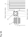
- the parts where plating or ceramic coating is to be applied are limited to those other than rolling contact surfaces of the inner ring 122 and the outer ring 124 as shown in Fig. 5A .
- the gap in the radial direction of the touchdown bearing 120 may be reduced according to variation in the film thickness, and the scope of control of the magnetic bearing 110 may be narrowed thereby.
- part of a plated film on the outer circumferential surface or the inner circumferential surface is damaged and peeled off thereby, and, in such a case, failure of the touchdown bearing 120 may occur if the peeled-off plated film is caught in the gap.
- the parts, to which plating or ceramic coating is applied, of the inner ring 122 and the outer ring 124 in the touchdown bearing 120 be limited to the parts where risk of corrosion is high, that is, the surfaces on the side close to the chamber 20 (or the cross-flow fan 30) among the surfaces perpendicular to the axis direction of the touchdown bearing 120.
- the touchdown bearing 120 has extremely high corrosion resistance against a halogen gas (especially, a fluorine gas). Further, by plating or ceramic coating the surfaces of the inner ring 122 and the outer ring 124 which comprise the NiCrAl alloy, scattering, in the chamber 20, of Cr (chromium) included in the inner ring 122 and the outer ring 124 can be prevented and polluting of the windows 23 and 24 due to the scattering can be suppressed, and, accordingly, shortening of the life of the chamber 20 can be suppressed.
- a halogen gas especially, a fluorine gas
- the above effect can be obtained without a hindrance to the driving ability of the touchdown bearing 120.
- the parts, to which plating or ceramic coating is applied to the surfaces on the side close to the chamber 20 (or the cross-flow fan 30) among the surfaces perpendicular to the axis direction of the touchdown bearing 120, the above effect can be obtained without narrowing the scope of control of the magnetic bearing 110. Further, similar effect can be obtained in the case that the construction using the plated or ceramic coated metal plates is adopted.
Landscapes
- Engineering & Computer Science (AREA)
- General Engineering & Computer Science (AREA)
- Mechanical Engineering (AREA)
- Physics & Mathematics (AREA)
- Electromagnetism (AREA)
- Optics & Photonics (AREA)
- Plasma & Fusion (AREA)
- Chemical & Material Sciences (AREA)
- Organic Chemistry (AREA)
- Metallurgy (AREA)
- Materials Engineering (AREA)
- Power Engineering (AREA)
- Magnetic Bearings And Hydrostatic Bearings (AREA)
- Rolling Contact Bearings (AREA)
- Lasers (AREA)
Abstract
Description
- The present invention relates to a bearing apparatus comprising a magnetic bearing and a touchdown bearing, more specifically, a bearing apparatus used in a fluorine gas environment. Further, the present invention relates to a laser apparatus comprising a bearing apparatus such as that explained above.
- A bearing apparatus, which is used in an environment wherein a corrosive gas such as a fluorine gas or the like exists, has been known. For example, each of Patent Literatures 1, 2, and 3 discloses a technique to prevent, in an excimer laser apparatus including a fluorine gas in a chamber thereof, corrosion due to the fluorine gas by coating a surface of a touchdown bearing, which holds a cross-flow fan, by a thin film comprising nickel, chromium nitride, or the like.
- PTL 1:
Japanese Patent Application Public Disclosure No. 2000-183436 - PTL 2:
Japanese Patent Application Public Disclosure No. 2002-168252 - PTL 3:
Japanese Patent Publication No. 6307436 - In the case that a touchdown bearing is used in a fluorine gas environment, it is necessary to regularly replace the touchdown bearing by the other, or improve corrosion resistance of the touchdown bearing. For improving corrosion resistance of the touchdown bearing, attempts such as constructing the touchdown bearing by using ceramic material, plating the touchdown bearing, and so on have been made. However, there are problems such that a ceramic bearing is expensive, a ceramic bearing is breakable, and a ceramic bearing having a large diameter cannot be manufactured. In the case of a plated touchdown bearing, manufacturing accuracy thereof is lowered due to plating, and a problem with respect to the lifetime thereof may occur if the plate comes off and the corrosion resistance is changed. Even in the construction wherein a surface of a touchdown bearing is coated by a thin film comprising nickel or chromium nitride like the construction disclosed in each of Patent Literatures 1, 2, and 3, there is a matter of concern, specifically, whether the durability of the film is sufficient, and, also, there is a problem that mechanical dimensional accuracy of respective parts of the bearing is deteriorated due to accumulated errors of film thicknesses.
- The present invention has been achieved in view of the above matters; and an object of the invention is to provide a bearing apparatus which is superior in corrosion resistance against a fluorine gas, and superior in dimensional accuracy and durability. Further, an object of the present invention is to provide a laser apparatus comprising a bearing apparatus such as that explained above.
- (Mode 1) According to Mode 1, a bearing apparatus which is used in an environment wherein a fluorine gas exists is provided, wherein the bearing apparatus comprises: a magnetic bearing comprising a magnetic member and an electromagnetic coil; and a touchdown bearing for protecting the magnetic bearing, wherein the touchdown bearing comprises an inner ring, an outer ring, and plural rolling members (balls, rollers, runners, or the like) arranged between the inner ring and the outer ring, wherein the inner ring and the outer ring in the touchdown bearing are constructed by using a NiCrAl alloy.
- (Mode 2) Mode 2 comprises the bearing apparatus of Mode 1, wherein the plural rolling members are constructed by using a NiCrAl alloy, additionally.
- (Mode 3) Mode 3 comprises the bearing apparatus of Mode 1, wherein the plural rolling members are constructed by using ceramic material, additionally.
- (Mode 4) Mode 4 comprises the bearing apparatus of any one of Modes 1-3, wherein the content of Ni in the NiCrAl alloy is equal to or greater than 50 weight percent.
- (Mode 5) Mode 5 comprises the bearing apparatus of any one of Modes 1-4, wherein the content of Cr in the NiCrAl alloy is equal to or greater than 30 weight percent.
- (Mode 6) Mode 6 comprises the bearing apparatus of any one of Modes 1-5, wherein the content of Al in the NiCrAl alloy is equal to or greater than 3 weight percent.
- (Mode 7) According to Mode 7, a laser apparatus is provided, wherein the laser apparatus comprises: a chamber in which a laser gas including a fluorine gas is enclosed, wherein the chamber comprises a fan for circulating the laser gas, a pair of discharge electrodes for making the laser gas discharge, and windows arranged to allow laser light to pass through them; and a bearing apparatus constructed to support the fan, wherein the bearing apparatus comprises a magnetic bearing comprising a magnetic member and an electromagnetic coil, and a touchdown bearing for protecting the magnetic bearing, wherein the touchdown bearing comprises an inner ring, an outer ring, and plural rolling members arranged between the inner ring and the outer ring, wherein the inner ring and the outer ring in the touchdown bearing are constructed by using a NiCrAl alloy.
- (Mode 8) Mode 8 comprises the laser apparatus of Mode 7, wherein the plural rolling members are constructed by using a NiCrAl alloy, additionally.
- (Mode 9) Mode 9 comprises the laser apparatus of Mode 7, wherein the plural rolling members are constructed by using ceramic material, additionally.
- (Mode 10)
Mode 10 comprises the laser apparatus of any one of Modes 7-9, wherein the content of Ni in the NiCrAl alloy is equal to or greater than 50 weight percent. - (Mode 11)
Mode 11 comprises the laser apparatus of any one of Modes 7-10, wherein the content of Cr in the NiCrAl alloy is equal to or greater than 30 weight percent. - (Mode 12) Mode 12 comprises the laser apparatus of any one of Modes 7-11, wherein the content of Al in the NiCrAl alloy is equal to or greater than 3 weight percent.
- (Mode 13) According to Mode 13, a laser apparatus is provided, wherein the laser apparatus comprises: a chamber in which a laser gas including a fluorine gas is enclosed, wherein the chamber comprises a fan for circulating the laser gas, a pair of discharge electrodes for making the laser gas discharge, and windows arranged to allow laser light to pass through them; and a bearing apparatus constructed to support the fan, wherein the bearing apparatus comprises a magnetic bearing comprising a magnetic member and an electromagnetic coil, and a touchdown bearing for protecting the magnetic bearing, wherein the touchdown bearing comprises an inner ring, an outer ring, and plural rolling members arranged between the inner ring and the outer ring, wherein the inner ring and the outer ring in the touchdown bearing are constructed by using a NiCrAl alloy, and the inner ring and the outer ring are plated by Ni or coated by ceramic material.
- (Mode 14) Mode 14 comprises the laser apparatus of Mode 13, wherein surfaces other than rolling contact surfaces of the inner ring and the outer ring are plated by Ni or coated by ceramic material.
- (Mode 15) Mode 15 comprises the laser apparatus of Mode 14, wherein surfaces which are perpendicular to the axis direction of the touchdown bearing and positioned on the side close to the chamber, among the surfaces of the inner ring and the outer ring, only are plated by Ni or coated by ceramic material.
- (Mode 16) According to Mode 16, a laser apparatus is provided, wherein the laser apparatus comprises: a chamber in which a laser gas including a fluorine gas is enclosed, wherein the chamber comprises a fan for circulating the laser gas, a pair of discharge electrodes for making the laser gas discharge, and windows arranged to allow laser light to pass through them; and a bearing apparatus constructed to support the fan, wherein the bearing apparatus comprises a magnetic bearing comprising a magnetic member and an electromagnetic coil, and a touchdown bearing for protecting the magnetic bearing, wherein the touchdown bearing comprises an inner ring, an outer ring, and plural rolling members arranged between the inner ring and the outer ring, wherein the inner ring and the outer ring in the touchdown bearing are constructed by using a NiCrAl alloy, and surfaces which are perpendicular to the axis direction of the touchdown bearing and positioned on the side close to the chamber, among the surfaces of the inner ring and the outer ring, are plated by Ni or coated by ceramic material.
-
Fig. 1 is a configuration diagram of a gas laser apparatus in which a bearing apparatus according to an embodiment of the present invention is adopted. -
Fig. 2 shows basic chemical and mechanical characteristics of a NiCrAl alloy that is adopted in a bearing apparatus according to an embodiment of the present invention. -
Fig. 3 shows result of experiments that were performed for checking corrosion resistance, against a HF solution, of a NiCrAl alloy that is adopted in a bearing apparatus according to an embodiment of the present invention. -
Fig. 4 is a configuration diagram of an excimer laser apparatus according to an embodiment of the present invention. -
Fig. 5A is a partial enlarged view of a part around a touchdown bearing in an excimer laser apparatus according to an embodiment of the present invention. -
Fig. 5B is a partial enlarged view of a part around a touchdown bearing in an excimer laser apparatus according to an embodiment of the present invention. - In the following description, embodiments of the present invention will be explained with reference to the figures. In the figures which will be explained below, a reference symbol that is the same as that assigned to one component is assigned to the other component which is the same as or corresponds to the one component, and overlapping explanation of these components will be omitted.
-
Fig. 1 is a configuration diagram of a gas laser apparatus in which a bearing apparatus according to an embodiment of the present invention is adopted. Abearing apparatus 100 can be incorporated in anexcimer laser apparatus 10, for example. Theexcimer laser apparatus 10 may be, for example, an ArF (argon/fluorine) excimer laser, KrF (krypton/fluorine) excimer laser, a XeCl (xenon/chlorine) excimer laser, or a XeF (xenon/fluorine) excimer laser. - As shown in
Fig. 1 , theexcimer laser apparatus 10 comprises achamber 20, across-flow fan 30, a rotatingshaft 40, amotor 50, and thebearing apparatuses 100. Theexcimer laser apparatus 10 further comprises a discharge electrode, a laser resonator, and so on which are not shown in the figure. - A mixed gas comprising a rare gas such as an Ar (argon) gas or the like and a halogen gas such as a F2 (fluorine) gas is enclosed in the
chamber 20. Thecross-flow fan 30 is arranged in thechamber 20, and used for circulating the mixed gas in thechamber 20. Themotor 50 rotates the rotatingshaft 40, and thecross-flow fan 30 attached to the rotatingshaft 40 rotates thereby. The rotatingshaft 40 and thecross-flow fan 30 attached to the rotatingshaft 40 are supported, on the both sides of the rotatingshaft 40, by thebearing apparatuses 100. - During operation of the
excimer laser apparatus 10, the mixed gas is circulated in thechamber 20 by thecross-flow fan 30, and the discharge electrode is activated to perform pulse discharging while the mixed gas is being circulated. As a result of pulse discharging, the states of rare gas atoms and halogen atoms are excited to become the states of excimer molecules so that radiation light is generated thereby, and, accordingly, laser oscillation occurs in the resonator and laser light is generated. - The
motor 50 and the bearingapparatuses 100 are arranged in ahousing 60 formed outside thechamber 20. Further, both ends of the rotatingshaft 40 of thecross-flow fan 30 extend to the outside of the chamber 202, thus, to the inside of thehousing 60. The inner space of thechamber 60 may not be isolated from the inner space of thechamber 20, and, in such a case, a mixed gas (a corrosive gas) that is the same as that existing in thechamber 20 exists in thehousing 60. In this regard, it is possible to adopt a construction for isolating the inner space of thechamber 60 from the inner space of thechamber 20 by using an appropriate construction or member; however, in such a case, there may be a risk that the mixed gas leaks from thechamber 20 to thehousing 60 due to incomplete isolation. Accordingly, the bearingapparatuses 100 are to be arranged in an environment wherein a corrosive gas exists. - The
motor 50 comprises arotor 52 and astator 54. Therotor 52 is attached, in an annularly arranging manner, on an outer circumferential surface of a part, which extends into thehousing 60, of the rotatingshaft 40. Thestator 54 is arranged on an inner wall of thehousing 60 in such a manner that thestator 54 faces therotor 52. Themotor 50 is constructed to generate a rotating magnetic field by making current flow through a coil of thestator 54, and rotate thereby the rotatingshaft 40 to which therotor 52 has been attached. - The
bearing apparatus 100 comprises a magnetic bearing 110 and a touchdown bearing 120. Themagnetic bearing 110 supports the rotatingshaft 40 of thecross-flow fan 30 in a noncontact manner by magnetic force. The touchdown bearing 120 is an auxiliary bearing for protecting themagnetic bearing 110, when themagnetic bearing 110 does not function normally (for example, in the case when supplying of electric power to themagnetic bearing 110 is stopped), by preventing the rotatingshaft 40 from colliding with the magnetic bearing 110 and breaking themagnetic bearing 110 thereby. The number of revolution of thecross-flow fan 30 is approximately several thousands rpm (for example, 4000-5000 rpm), and the performance of themagnetic bearing 110 is dependent on clearance thereof. It is preferable that the clearance be set as narrow as possible; and if the clearance of themagnetic bearing 110 is set to be narrow, the clearance of the touchdown bearing 120 becomes narrow further. For example, there is a case wherein the clearance of the touchdown bearing 120 is set to that equal to or less than 0.1 mm. The number of occurrence of touchdown (contacting of therotating shaft 40 with the touchdown bearing 120) is not so much, since touchdown occurs when an emergency such as sudden power shutdown or the like has occurred; however, since it is necessary to stop thecross-flow fan 30 safely when an emergency has occurred, the technique relating thereto is an important technique for ensuring safety. - The
magnetic bearing 110 comprises amagnetic member 112 on a rotor side and anelectromagnetic coil 114 on a housing side. The rotor-sidemagnetic member 112 is attached, in an annularly arranging manner, on an outer circumferential surface of a part, which extends into thehousing 60, of therotating shaft 40. The housing-sideelectromagnetic coil 114 is arranged on an inner wall of thehousing 60 in such a manner that the housing-sideelectromagnetic coil 114 faces the rotor-sidemagnetic member 112. Themagnetic bearing 110 is constructed to receive, in a noncontact manner, the rotatingshaft 40 of thecross-flow fan 30, by making current flow through the housing-sideelectromagnetic coil 114 and generating thereby magnetic attraction force between the rotor-sidemagnetic member 112 and the housing-sideelectromagnetic coil 114. Themagnetic bearing 110 may further comprise a sensor (for example, a magnetic sensor) which is not shown in the figure for detecting the size of the gap between the rotor-sidemagnetic member 112 and the housing-sideelectromagnetic coil 114, and may be constructed to adjust, based on a signal from the sensor, current supplied to the housing-sideelectromagnetic coil 114 to thereby keep the size of the gap between the rotor-sidemagnetic member 112 and the housing-sideelectromagnetic coil 114 constant. - The
touchdown bearing 120 comprises aninner ring 122, anouter ring 124, and plural rolling members (balls or rollers) 126. Theouter ring 124 is fixed to the inner wall of thehousing 60, and theplural rolling members 126 are arranged in a gap formed between theouter ring 124 and theinner ring 122 in such a manner that theplural rolling members 126 are held between the above rings. Each of the rollingmembers 126 is in contact with the outer circumferential surface of theinner ring 122 and the inner circumferential surface of theouter ring 124, and theinner ring 122 is movable relative to theouter ring 124. A gap has been set between the inner circumferential surface of the inner ring 122 (that is, the surface facing the rotating shaft 40) and therotating shaft 40, wherein the gap is smaller than that between the rotor-sidemagnetic member 112 and the housing-sideelectromagnetic coil 114 in themagnetic bearing 110. Thus, in the case that themagnetic bearing 110 does not function normally (due to shortage of magnetic repulsion force of themagnetic bearing 110 or the like), contacting between the rotor-sidemagnetic member 112 and the housing-sideelectromagnetic coil 114 in themagnetic bearing 110 can be avoided by making theinner ring 122 of the touchdown bearing 120 come in contact with the rotatingshaft 40. As explained above, during the time when themagnetic bearing 110 works abnormally, the touchdown bearing 120 comes in contact with the rotatingshaft 40 of thecross-flow fan 30 and supports it in place of themagnetic bearing 110. Thus, damaging to themagnetic bearing 110 can be prevented. - Since the mixed gas in the
chamber 20 exists in the inner space of thehousing 60 as explained above, the touchdown bearing 120 is always exposed to a halogen gas such as a F2 (fluorine) gas, and the gas corrodes the touchdown bearing 120 if it is that constructed by using material having no corrosion resistance. - For preventing corrosion of the touchdown bearing 120 due to the halogen gas, it is preferable that the
inner ring 122 and theouter ring 124 in the touchdown bearing 120 be constructed by using a NiCrAl alloy. Similarly, theplural rolling members 126 in the touchdown bearing 120 may be constructed by using a NiCrAl alloy, or they may be ceramic rolling members. The NiCrAl alloy is an alloy comprising, as components thereof, Ni (nickel), Cr (chromium), and Al (aluminum). For example, theinner ring 122, theouter ring 124, and the rollingmembers 126 in the touchdown bearing 120 may comprise a NiCrAl alloy in which the content of Ni is equal to or greater than 50 weight percent. Further, the content of Cr in the above NiCrAl alloy may be equal to or grater than 30 weight percent, and, further, the content of Al may be equal to or grater than 3 weight percent. - In this regard, the expression "comprise a NiCrAl alloy" herein means that the whole of the
inner ring 122, the whole of theouter ring 124, and the whole of the rollingmembers 126 in the touchdown bearing 120 (i.e., not only the surfaces thereof but also the interior parts thereof) are constructed by using the NiCrAl alloy. Thus, regarding theinner ring 122, theouter ring 124, and the rollingmembers 126, such as those explained above, in the touchdown bearing 120, their durability is high since the surfaces of them are not coated by thin films, and they can be manufactured with high manufacturing accuracy. However, regarding theinner ring 122, theouter ring 124, or the rollingmembers 126 in the touchdown bearing 120, the surface(s) thereof only may be coated by a thin film(s) comprising a NiCrAl alloy (by applying a thin-film forming technique such as plating, vapor deposition, or the like, for example) and the interior part(s) thereof may be constructed by using material comprising different metal, ceramic material, or the like. - The inventors of the present invention have confirmed by performing experiments that a NiCrAl alloy having composition such as that explained above has extremely high corrosion resistance against a F2 (fluorine) gas, especially.
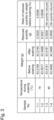
Fig. 2 shows basic chemical and mechanical characteristics of a NiCrAl alloy used in the experiments. The content of Ni was 58.2 weight percent, the content of Cr was 38 weight percent, and the content of Al was 3.8 weight percent. Further, the tensile strength was equal to or greater than 1500 N/mm2, and the hardness (HRC) was approximately 57. The hardness is similar to that of SUS440C, so that it can be understood that the NiCrAl alloy has mechanical characteristics that are sufficient as those of material for a touchdown bearing. - For examining the corrosion resistance of a NiCrAl alloy against a F2 (fluorine) gas, four samples, each comprising the NiCrAl alloy having the above composition and having the form of a block having the size of 20x20x15 mm, were prepared; two of the samples are soaked in a one-percent HF (hydrofluoric acid) solution, that is maintained at the temperature of 45 degrees Celsius, for one hour, and the remaining two of the samples are soaked in a one-percent HF solution, that is maintained at the temperature of 75 degrees Celsius, for one hour; and change in the weight of each of the samples was measured. Result of the examinations is shown in
Fig. 3 . - In the case that the temperature of the HF solution during soaking was 45 degrees Celsius, thinning due to corrosion was not observed in any of the samples. On the other hand, in the case that the temperature of the HF solution during soaking was 75 degrees Celsius, minor thinning due to corrosion could be observed in each of the samples; however, the ratio of the quantity reduced as a result of thinning to the weight of the sample before soaking thereof into the HF solution was merely 0.0048 percent. Further, with respect to the external appearance of each of the samples after soaking, although the sample soaked into the 75-degrees-Celsius HF solution has lost its gloss slightly, no major change in the external appearance of the sample could be observed.
- As explained above, it has been discovered that the NiCrAl alloy used in the experiments has high corrosion resistance against the HF solution, and, accordingly, it is expected that the NiCrAl alloy has high corrosion resistance against a F2 (fluorine) gas.
- Accordingly, the touchdown bearing 120 comprising the NiCrAl alloy according to the present disclosure is not corroded even in an environment where a F2 (fluorine) gas exists, and, accordingly, can continuously work normally. Further, since the
inner ring 122, theouter ring 124, and the rollingmembers 126, which comprise the NiCrAl alloy according to the present disclosure, in the touchdown bearing 120 can be manufactured by performing a machining process (i.e., without performing a coating process for forming a thin film comprising a NiCrAl alloy), the touchdown bearing 120 having high dimensional accuracy can be realized. -
Fig. 4 is a configuration diagram of an excimer laser apparatus according to an embodiment of the present invention. Anexcimer laser apparatus 11 comprises achamber 20, across-flow fan 30, a rotatingshaft 40, amotor 50, abearing apparatus 100, and a pair of resonance mirrors 70. Thechamber 20 comprises a pair ofdischarge electrodes 22 andwindows Fig. 1 . Thechamber 20, thecross-flow fan 30, the rotatingshaft 40, themotor 50, and thebearing apparatus 100 are the same as those explained in relation to theexcimer laser apparatus 10 shown inFig. 1 , so that overlapping explanation of the above components will be omitted herein. The pair of resonance mirrors 70 form a laser resonator. - During operation of the
excimer laser apparatus 11, a mixed gas, which comprises a rare gas such as an Ar (argon) gas or the like and a halogen gas such as a F2 (fluorine) gas, is circulated in thechamber 20 by thecross-flow fan 30, and thedischarge electrodes 22 are activated to perform pulse discharging while the mixed gas is being circulated. As a result of pulse discharging, the states of rare gas atoms and halogen atoms are excited to become the states of excimer molecules, so that radiation light is generated thereby. The radiation light reciprocally moves within the laser resonator (i.e., between the pair of resonance mirrors 70) via thewindows - Similar to the case of the
excimer laser apparatus 10 shown inFig. 1 , for preventing corrosion of a touchdown bearing 120 in theexcimer laser apparatus 11 shown inFig. 4 due to the halogen gas, it is preferable that aninner ring 122 and anouter ring 124 in the touchdown bearing 120 be constructed by using a NiCrAl alloy. Further, in theexcimer laser apparatus 11 according to the present embodiment, it is preferable that surfaces of theinner ring 122 and theouter ring 124, which are constructed by using the NiCrAl alloy, in the touchdown bearing 120 be plated by Ni (nickel) or material comprising Ni, or coated by ceramic material. In order to prevent a hindrance to the driving ability of the touchdown bearing 120 (i.e., for avoiding occurrence of rotation failure due to peeling off of a plated film from a rolling contact surface), the parts where plating or ceramic coating is to be applied are limited to those other than rolling contact surfaces of theinner ring 122 and theouter ring 124 as shown inFig. 5A . - In this regard, in the case that the outer circumferential surface and the inner circumferential surface of the touchdown bearing 120 (i.e., the surfaces perpendicular to the radial direction of the touchdown bearing 120) are plated or ceramic coated, the gap in the radial direction of the touchdown bearing 120 may be reduced according to variation in the film thickness, and the scope of control of the
magnetic bearing 110 may be narrowed thereby. Further, there may be a case wherein part of a plated film on the outer circumferential surface or the inner circumferential surface is damaged and peeled off thereby, and, in such a case, failure of the touchdown bearing 120 may occur if the peeled-off plated film is caught in the gap. On the other hand, it is required that a surface(s) on the side close to the chamber 20 (or the cross-flow fan 30), among the surfaces perpendicular to the axis direction of the touchdown bearing 120, be superior in corrosion resistance than other surfaces since the risk of corrosion therein due to a halogen gas is high. - Thus, as shown in
Fig. 5B , it is more desirable that the parts, to which plating or ceramic coating is applied, of theinner ring 122 and theouter ring 124 in the touchdown bearing 120 be limited to the parts where risk of corrosion is high, that is, the surfaces on the side close to the chamber 20 (or the cross-flow fan 30) among the surfaces perpendicular to the axis direction of thetouchdown bearing 120. - In this regard, in place of the above-explained construction wherein the
inner ring 122 and theouter ring 124 in the touchdown bearing 120 are plated or ceramic coated, it may be possible to adopt a construction wherein the surfaces of theinner ring 122 and theouter ring 124 in the touchdown bearing 120 are covered by plated or ceramic coated metal plates comprising Al (aluminum) or the like. The parts which are to be covered by metal plates may be the same as the above-explained parts to which plating or ceramic coating is applied. - The
touchdown bearing 120 according to the present embodiment has extremely high corrosion resistance against a halogen gas (especially, a fluorine gas). Further, by plating or ceramic coating the surfaces of theinner ring 122 and theouter ring 124 which comprise the NiCrAl alloy, scattering, in thechamber 20, of Cr (chromium) included in theinner ring 122 and theouter ring 124 can be prevented and polluting of thewindows chamber 20 can be suppressed. - Further, by limiting the parts, to which plating or ceramic coating is applied, to those other than the rolling contact surfaces of the
inner ring 122 and theouter ring 124, the above effect can be obtained without a hindrance to the driving ability of thetouchdown bearing 120. Further, by limiting the parts, to which plating or ceramic coating is applied, to the surfaces on the side close to the chamber 20 (or the cross-flow fan 30) among the surfaces perpendicular to the axis direction of the touchdown bearing 120, the above effect can be obtained without narrowing the scope of control of themagnetic bearing 110. Further, similar effect can be obtained in the case that the construction using the plated or ceramic coated metal plates is adopted. - In the above description, embodiments of the present invention have been explained based on some examples; and, in this regard, the above explained embodiments of the present invention are those used for facilitating understanding of the present invention, and are not those used for limiting the present invention. It is obvious that the present invention can be changed or modified without departing from the scope of the gist thereof, and that the present invention includes equivalents thereof. Further, it is possible to arbitrarily combine components or omit a component(s) disclosed in the claims and the specification, within the scope that at least part of the above-stated problems can be solved or within the scope that at least part of advantageous effect can be obtained.
- 10
- Excimer laser apparatus
- 20
- Chamber
- 30
- Cross-flow fan
- 40
- Rotating shaft
- 50
- Motor
- 52
- Rotor
- 54
- Stator
- 60
- Housing
- 100
- Bearing apparatus
- 110
- Magnetic bearing
- 112
- Rotor-side magnetic member
- 114
- Housing-side electromagnetic coil
- 120
- Touchdown bearing
- 122
- Inner ring
- 124
- Outer ring
- 126
- Rolling member
- 11
- Excimer laser apparatus
- 22
- Discharge electrode
- 23, 24
- Window
- 70
- Resonance mirror
Claims (16)
- A bearing apparatus for use in an environment where a fluorine gas exists, comprising:a magnetic bearing comprising a magnetic member and an electromagnetic coil; anda touchdown bearing for protecting the magnetic bearing, wherein the touchdown bearing comprises an inner ring, an outer ring, and plural rolling members arranged between the inner ring and the outer ring; whereinthe inner ring and the outer ring in the touchdown bearing are constructed by using a NiCrAl alloy.
- The bearing apparatus as recited in Claim 1, wherein the plural rolling members are constructed by using a NiCrAl alloy.
- The bearing apparatus as recited in Claim 1, wherein the plural rolling members are constructed by using ceramic material.
- The bearing apparatus as recited in any one of Claims 1-3, wherein the content of Ni in the NiCrAl alloy is equal to or greater than 50 weight percent.
- The bearing apparatus as recited in any one of Claims 1-4, wherein the content of Cr in the NiCrAl alloy is equal to or greater than 30 weight percent.
- The bearing apparatus as recited in any one of Claims 1-5, wherein the content of Al in the NiCrAl alloy is equal to or greater than 3 weight percent.
- A laser apparatus comprising:a chamber in which a laser gas including a fluorine gas is enclosed, wherein the chamber comprisesa fan for circulating the laser gas,a pair of discharge electrodes for making the laser gas discharge, andwindows arranged to allow laser light to pass through them; anda bearing apparatus configured to support the fan, wherein the bearing apparatus comprisesa magnetic bearing comprising a magnetic member and an electromagnetic coil, anda touchdown bearing for protecting the magnetic bearing, wherein the touchdown bearing comprises an inner ring, an outer ring, and plural rolling members arranged between the inner ring and the outer ring, whereinthe inner ring and the outer ring in the touchdown bearing are constructed by using a NiCrAl alloy.
- The laser apparatus as recited in Claim 7, wherein the plural rolling members are constructed by using a NiCrAl alloy.
- The laser apparatus as recited in Claim 7, wherein the plural rolling members are constructed by using ceramic material.
- The laser apparatus as recited in any one of Claims 7-9, wherein the content of Ni in the NiCrAl alloy is equal to or greater than 50 weight percent.
- The laser apparatus as recited in any one of Claims 7-10, wherein the content of Cr in the NiCrAl alloy is equal to or greater than 30 weight percent.
- The laser apparatus as recited in any one of Claims 7-11, wherein the content of Al in the NiCrAl alloy is equal to or greater than 3 weight percent.
- A laser apparatus comprising:a chamber in which a laser gas including a fluorine gas is enclosed, wherein the chamber comprisesa fan for circulating the laser gas,a pair of discharge electrodes for making the laser gas discharge, and windows arranged to allow laser light to pass through them; anda bearing apparatus configured to support the fan, wherein the bearing apparatus comprisesa magnetic bearing comprising a magnetic member and an electromagnetic coil, anda touchdown bearing for protecting the magnetic bearing, wherein the touchdown bearing comprises an inner ring, an outer ring, and plural rolling members arranged between the inner ring and the outer ring, whereinthe inner ring and the outer ring in the touchdown bearing are constructed by using a NiCrAl alloy, and the inner ring and the outer ring are plated by Ni or coated by ceramic material.
- The laser apparatus as recited in Claim 13, wherein surfaces other than rolling contact surfaces of the inner ring and the outer ring are plated by Ni or coated by ceramic material.
- The laser apparatus as recited in Claim 14, wherein only surfaces which are perpendicular to the axis direction of the touchdown bearing and positioned on the side close to the chamber, among the surfaces of the inner ring and the outer ring, are plated by Ni or coated by ceramic material.
- A laser apparatus comprising:a chamber in which a laser gas including a fluorine gas is enclosed, wherein the chamber comprisesa fan for circulating the laser gas,a pair of discharge electrodes for making the laser gas discharge, and windows arranged to allow laser light to pass through them; anda bearing apparatus configured to support the fan, wherein the bearing apparatus comprisesa magnetic bearing comprising a magnetic member and an electromagnetic coil, anda touchdown bearing for protecting the magnetic bearing, wherein the touchdown bearing comprises an inner ring, an outer ring, and plural rolling members arranged between the inner ring and the outer ring, whereinthe inner ring and the outer ring in the touchdown bearing are constructed by using a NiCrAl alloy, and surfaces which are perpendicular to the axis direction of the touchdown bearing and positioned on the side close to the chamber, among the surfaces of the inner ring and the outer ring, are covered by metal plates, wherein the metal plates are plated by Ni or coated by ceramic material.
Applications Claiming Priority (1)
| Application Number | Priority Date | Filing Date | Title |
|---|---|---|---|
| JP2022120476A JP2024017670A (en) | 2022-07-28 | 2022-07-28 | Bearing devices and laser devices equipped with bearing devices |
Publications (2)
| Publication Number | Publication Date |
|---|---|
| EP4311951A1 true EP4311951A1 (en) | 2024-01-31 |
| EP4311951B1 EP4311951B1 (en) | 2025-10-29 |
Family
ID=87517181
Family Applications (1)
| Application Number | Title | Priority Date | Filing Date |
|---|---|---|---|
| EP23187952.9A Active EP4311951B1 (en) | 2022-07-28 | 2023-07-26 | Bearing apparatus and laser apparatus comprising bearing apparatus |
Country Status (6)
| Country | Link |
|---|---|
| US (1) | US20240035514A1 (en) |
| EP (1) | EP4311951B1 (en) |
| JP (1) | JP2024017670A (en) |
| KR (1) | KR20240016208A (en) |
| CN (1) | CN117469300A (en) |
| TW (1) | TW202413816A (en) |
Citations (4)
| Publication number | Priority date | Publication date | Assignee | Title |
|---|---|---|---|---|
| JP2000183436A (en) | 1998-12-18 | 2000-06-30 | Komatsu Ltd | Excimer laser device |
| JP2002168252A (en) | 2000-11-29 | 2002-06-14 | Nsk Ltd | Touchdown bearing |
| US20150249312A1 (en) * | 2012-11-05 | 2015-09-03 | Gigaphoton Inc. | Laser chamber and discharge excitation gas laser apparatus |
| CN113550980A (en) * | 2021-06-22 | 2021-10-26 | 河南科技大学 | High-performance composite insulating coating sprayed on the surface of rolling bearing and preparation method thereof |
Family Cites Families (3)
| Publication number | Priority date | Publication date | Assignee | Title |
|---|---|---|---|---|
| JPS637436U (en) | 1986-06-30 | 1988-01-19 | ||
| JP2005172056A (en) * | 2003-12-09 | 2005-06-30 | Ntn Corp | Non-magnetic rolling bearing |
| JP2009222139A (en) * | 2008-03-17 | 2009-10-01 | Nsk Ltd | Rolling bearing and rolling bearing with alignment ring |
-
2022
- 2022-07-28 JP JP2022120476A patent/JP2024017670A/en active Pending
-
2023
- 2023-07-24 TW TW112127587A patent/TW202413816A/en unknown
- 2023-07-24 US US18/357,356 patent/US20240035514A1/en active Pending
- 2023-07-24 KR KR1020230095753A patent/KR20240016208A/en active Pending
- 2023-07-26 EP EP23187952.9A patent/EP4311951B1/en active Active
- 2023-07-27 CN CN202310932613.8A patent/CN117469300A/en active Pending
Patent Citations (6)
| Publication number | Priority date | Publication date | Assignee | Title |
|---|---|---|---|---|
| JP2000183436A (en) | 1998-12-18 | 2000-06-30 | Komatsu Ltd | Excimer laser device |
| US6577664B1 (en) * | 1998-12-18 | 2003-06-10 | Komatsu Ltd. | Excimer laser device |
| JP2002168252A (en) | 2000-11-29 | 2002-06-14 | Nsk Ltd | Touchdown bearing |
| US20150249312A1 (en) * | 2012-11-05 | 2015-09-03 | Gigaphoton Inc. | Laser chamber and discharge excitation gas laser apparatus |
| JP6307436B2 (en) | 2012-11-05 | 2018-04-04 | ギガフォトン株式会社 | Laser chamber and discharge excitation gas laser apparatus |
| CN113550980A (en) * | 2021-06-22 | 2021-10-26 | 河南科技大学 | High-performance composite insulating coating sprayed on the surface of rolling bearing and preparation method thereof |
Also Published As
| Publication number | Publication date |
|---|---|
| KR20240016208A (en) | 2024-02-06 |
| CN117469300A (en) | 2024-01-30 |
| EP4311951B1 (en) | 2025-10-29 |
| US20240035514A1 (en) | 2024-02-01 |
| TW202413816A (en) | 2024-04-01 |
| JP2024017670A (en) | 2024-02-08 |
Similar Documents
| Publication | Publication Date | Title |
|---|---|---|
| EP1281869B1 (en) | Scroll type compressor | |
| KR101175362B1 (en) | Vacuum pump | |
| JP2000077747A (en) | Pulse-type laser system blower assembly provided with built-in ceramic bearing | |
| US6026103A (en) | Gas discharge laser with roller bearings and stable magnetic axial positioning | |
| US20100316502A1 (en) | Method of manufacturing impeller of centrifugal rotary machine and impeller of centrifugal rotary machine | |
| EP1137126B1 (en) | Electric discharge excitation excimer laser | |
| EP1505171B1 (en) | Ion implantation of turbine engine rotor component | |
| US20240035514A1 (en) | Bearing apparatus and laser apparatus comprising bearing apparatus | |
| JP2003148389A (en) | Vacuum pump | |
| US5624191A (en) | Metal lubricated plain bearing having a bearing part adjoining a bearing surface wetted with liquid metal during operation | |
| JPWO2000033431A1 (en) | Discharge-pumped excimer laser device | |
| EP1047162B1 (en) | Excimer laser device | |
| Srinivasan et al. | Degradation of MCrAlY Coating and substrate superalloy during long term thermal exposure | |
| JP3877912B2 (en) | Discharge excitation excimer laser equipment | |
| US6577664B1 (en) | Excimer laser device | |
| EP1451527A1 (en) | Current control biasing to protect electrode seals of a ring laser gyroscope | |
| JP2001044533A5 (en) | ||
| US6532246B1 (en) | Excimer laser apparatus | |
| Manimaran et al. | Analysis of surface texture of Ni-based super alloy with thermal barrier coating system (TBC) for gas turbine blade | |
| JP4995632B2 (en) | Vacuum pump | |
| CN115038876B (en) | Vacuum pump and controller | |
| JP2000150986A (en) | Excimer laser device | |
| JP3809879B2 (en) | Excimer laser oscillation apparatus having a laser chamber having an alumina film formed by alumite treatment | |
| US20250092557A1 (en) | Coating protection for stator vanes and methods of protection thereof | |
| JP2002168252A (en) | Touchdown bearing |
Legal Events
| Date | Code | Title | Description |
|---|---|---|---|
| PUAI | Public reference made under article 153(3) epc to a published international application that has entered the european phase |
Free format text: ORIGINAL CODE: 0009012 |
|
| STAA | Information on the status of an ep patent application or granted ep patent |
Free format text: STATUS: THE APPLICATION HAS BEEN PUBLISHED |
|
| AK | Designated contracting states |
Kind code of ref document: A1 Designated state(s): AL AT BE BG CH CY CZ DE DK EE ES FI FR GB GR HR HU IE IS IT LI LT LU LV MC ME MK MT NL NO PL PT RO RS SE SI SK SM TR |
|
| RAP1 | Party data changed (applicant data changed or rights of an application transferred) |
Owner name: EBARA CORPORATION |
|
| STAA | Information on the status of an ep patent application or granted ep patent |
Free format text: STATUS: REQUEST FOR EXAMINATION WAS MADE |
|
| 17P | Request for examination filed |
Effective date: 20240704 |
|
| RBV | Designated contracting states (corrected) |
Designated state(s): AL AT BE BG CH CY CZ DE DK EE ES FI FR GB GR HR HU IE IS IT LI LT LU LV MC ME MK MT NL NO PL PT RO RS SE SI SK SM TR |
|
| GRAP | Despatch of communication of intention to grant a patent |
Free format text: ORIGINAL CODE: EPIDOSNIGR1 |
|
| STAA | Information on the status of an ep patent application or granted ep patent |
Free format text: STATUS: GRANT OF PATENT IS INTENDED |
|
| INTG | Intention to grant announced |
Effective date: 20250526 |
|
| GRAS | Grant fee paid |
Free format text: ORIGINAL CODE: EPIDOSNIGR3 |
|
| GRAA | (expected) grant |
Free format text: ORIGINAL CODE: 0009210 |
|
| STAA | Information on the status of an ep patent application or granted ep patent |
Free format text: STATUS: THE PATENT HAS BEEN GRANTED |
|
| AK | Designated contracting states |
Kind code of ref document: B1 Designated state(s): AL AT BE BG CH CY CZ DE DK EE ES FI FR GB GR HR HU IE IS IT LI LT LU LV MC ME MK MT NL NO PL PT RO RS SE SI SK SM TR |
|
| REG | Reference to a national code |
Ref country code: CH Ref legal event code: F10 Free format text: ST27 STATUS EVENT CODE: U-0-0-F10-F00 (AS PROVIDED BY THE NATIONAL OFFICE) Effective date: 20251029 Ref country code: GB Ref legal event code: FG4D Ref country code: CH Ref legal event code: R17 Free format text: ST27 STATUS EVENT CODE: U-0-0-R10-R17 (AS PROVIDED BY THE NATIONAL OFFICE) Effective date: 20251029 |
|
| REG | Reference to a national code |
Ref country code: DE Ref legal event code: R096 Ref document number: 602023007959 Country of ref document: DE |
|
| P01 | Opt-out of the competence of the unified patent court (upc) registered |
Free format text: CASE NUMBER: UPC_APP_9725_4311951/2025 Effective date: 20251013 |
|
| REG | Reference to a national code |
Ref country code: IE Ref legal event code: FG4D |
|
| REG | Reference to a national code |
Ref country code: NL Ref legal event code: FP |
|
| PG25 | Lapsed in a contracting state [announced via postgrant information from national office to epo] |
Ref country code: ES Free format text: LAPSE BECAUSE OF FAILURE TO SUBMIT A TRANSLATION OF THE DESCRIPTION OR TO PAY THE FEE WITHIN THE PRESCRIBED TIME-LIMIT Effective date: 20251029 |
|
| REG | Reference to a national code |
Ref country code: LT Ref legal event code: MG9D |
|
| PG25 | Lapsed in a contracting state [announced via postgrant information from national office to epo] |
Ref country code: NO Free format text: LAPSE BECAUSE OF FAILURE TO SUBMIT A TRANSLATION OF THE DESCRIPTION OR TO PAY THE FEE WITHIN THE PRESCRIBED TIME-LIMIT Effective date: 20260129 |
|
| PG25 | Lapsed in a contracting state [announced via postgrant information from national office to epo] |
Ref country code: HR Free format text: LAPSE BECAUSE OF FAILURE TO SUBMIT A TRANSLATION OF THE DESCRIPTION OR TO PAY THE FEE WITHIN THE PRESCRIBED TIME-LIMIT Effective date: 20251029 Ref country code: AT Free format text: LAPSE BECAUSE OF FAILURE TO SUBMIT A TRANSLATION OF THE DESCRIPTION OR TO PAY THE FEE WITHIN THE PRESCRIBED TIME-LIMIT Effective date: 20251029 Ref country code: FI Free format text: LAPSE BECAUSE OF FAILURE TO SUBMIT A TRANSLATION OF THE DESCRIPTION OR TO PAY THE FEE WITHIN THE PRESCRIBED TIME-LIMIT Effective date: 20251029 |
|
| REG | Reference to a national code |
Ref country code: AT Ref legal event code: MK05 Ref document number: 1851838 Country of ref document: AT Kind code of ref document: T Effective date: 20251029 |
|
| PG25 | Lapsed in a contracting state [announced via postgrant information from national office to epo] |
Ref country code: RS Free format text: LAPSE BECAUSE OF FAILURE TO SUBMIT A TRANSLATION OF THE DESCRIPTION OR TO PAY THE FEE WITHIN THE PRESCRIBED TIME-LIMIT Effective date: 20260129 |
|
| PG25 | Lapsed in a contracting state [announced via postgrant information from national office to epo] |
Ref country code: IS Free format text: LAPSE BECAUSE OF FAILURE TO SUBMIT A TRANSLATION OF THE DESCRIPTION OR TO PAY THE FEE WITHIN THE PRESCRIBED TIME-LIMIT Effective date: 20260228 |
|
| PG25 | Lapsed in a contracting state [announced via postgrant information from national office to epo] |
Ref country code: PT Free format text: LAPSE BECAUSE OF FAILURE TO SUBMIT A TRANSLATION OF THE DESCRIPTION OR TO PAY THE FEE WITHIN THE PRESCRIBED TIME-LIMIT Effective date: 20260302 |
|
| PG25 | Lapsed in a contracting state [announced via postgrant information from national office to epo] |
Ref country code: PL Free format text: LAPSE BECAUSE OF FAILURE TO SUBMIT A TRANSLATION OF THE DESCRIPTION OR TO PAY THE FEE WITHIN THE PRESCRIBED TIME-LIMIT Effective date: 20251029 |
|
| PG25 | Lapsed in a contracting state [announced via postgrant information from national office to epo] |
Ref country code: LV Free format text: LAPSE BECAUSE OF FAILURE TO SUBMIT A TRANSLATION OF THE DESCRIPTION OR TO PAY THE FEE WITHIN THE PRESCRIBED TIME-LIMIT Effective date: 20251029 |
|
| PG25 | Lapsed in a contracting state [announced via postgrant information from national office to epo] |
Ref country code: BG Free format text: LAPSE BECAUSE OF FAILURE TO SUBMIT A TRANSLATION OF THE DESCRIPTION OR TO PAY THE FEE WITHIN THE PRESCRIBED TIME-LIMIT Effective date: 20251029 |