EP4311914A1 - Turbine blade - Google Patents
Turbine blade Download PDFInfo
- Publication number
- EP4311914A1 EP4311914A1 EP23176408.5A EP23176408A EP4311914A1 EP 4311914 A1 EP4311914 A1 EP 4311914A1 EP 23176408 A EP23176408 A EP 23176408A EP 4311914 A1 EP4311914 A1 EP 4311914A1
- Authority
- EP
- European Patent Office
- Prior art keywords
- blade
- tip
- wall
- turbine
- trailing edge
- Prior art date
- Legal status (The legal status is an assumption and is not a legal conclusion. Google has not performed a legal analysis and makes no representation as to the accuracy of the status listed.)
- Granted
Links
Images

Classifications
-
- F—MECHANICAL ENGINEERING; LIGHTING; HEATING; WEAPONS; BLASTING
- F01—MACHINES OR ENGINES IN GENERAL; ENGINE PLANTS IN GENERAL; STEAM ENGINES
- F01D—NON-POSITIVE DISPLACEMENT MACHINES OR ENGINES, e.g. STEAM TURBINES
- F01D5/00—Blades; Blade-carrying members; Heating, heat-insulating, cooling or antivibration means on the blades or the members
- F01D5/12—Blades
- F01D5/14—Form or construction
- F01D5/141—Shape, i.e. outer, aerodynamic form
-
- F—MECHANICAL ENGINEERING; LIGHTING; HEATING; WEAPONS; BLASTING
- F01—MACHINES OR ENGINES IN GENERAL; ENGINE PLANTS IN GENERAL; STEAM ENGINES
- F01D—NON-POSITIVE DISPLACEMENT MACHINES OR ENGINES, e.g. STEAM TURBINES
- F01D5/00—Blades; Blade-carrying members; Heating, heat-insulating, cooling or antivibration means on the blades or the members
- F01D5/12—Blades
- F01D5/14—Form or construction
- F01D5/18—Hollow blades, i.e. blades with cooling or heating channels or cavities; Heating, heat-insulating or cooling means on blades
-
- F—MECHANICAL ENGINEERING; LIGHTING; HEATING; WEAPONS; BLASTING
- F01—MACHINES OR ENGINES IN GENERAL; ENGINE PLANTS IN GENERAL; STEAM ENGINES
- F01D—NON-POSITIVE DISPLACEMENT MACHINES OR ENGINES, e.g. STEAM TURBINES
- F01D5/00—Blades; Blade-carrying members; Heating, heat-insulating, cooling or antivibration means on the blades or the members
- F01D5/12—Blades
- F01D5/14—Form or construction
- F01D5/20—Specially-shaped blade tips to seal space between tips and stator
-
- F—MECHANICAL ENGINEERING; LIGHTING; HEATING; WEAPONS; BLASTING
- F01—MACHINES OR ENGINES IN GENERAL; ENGINE PLANTS IN GENERAL; STEAM ENGINES
- F01D—NON-POSITIVE DISPLACEMENT MACHINES OR ENGINES, e.g. STEAM TURBINES
- F01D5/00—Blades; Blade-carrying members; Heating, heat-insulating, cooling or antivibration means on the blades or the members
- F01D5/12—Blades
- F01D5/14—Form or construction
- F01D5/147—Construction, i.e. structural features, e.g. of weight-saving hollow blades
-
- F—MECHANICAL ENGINEERING; LIGHTING; HEATING; WEAPONS; BLASTING
- F01—MACHINES OR ENGINES IN GENERAL; ENGINE PLANTS IN GENERAL; STEAM ENGINES
- F01D—NON-POSITIVE DISPLACEMENT MACHINES OR ENGINES, e.g. STEAM TURBINES
- F01D5/00—Blades; Blade-carrying members; Heating, heat-insulating, cooling or antivibration means on the blades or the members
- F01D5/12—Blades
- F01D5/28—Selecting particular materials; Particular measures relating thereto; Measures against erosion or corrosion
- F01D5/286—Particular treatment of blades, e.g. to increase durability or resistance against corrosion or erosion
-
- F—MECHANICAL ENGINEERING; LIGHTING; HEATING; WEAPONS; BLASTING
- F01—MACHINES OR ENGINES IN GENERAL; ENGINE PLANTS IN GENERAL; STEAM ENGINES
- F01D—NON-POSITIVE DISPLACEMENT MACHINES OR ENGINES, e.g. STEAM TURBINES
- F01D5/00—Blades; Blade-carrying members; Heating, heat-insulating, cooling or antivibration means on the blades or the members
- F01D5/12—Blades
- F01D5/28—Selecting particular materials; Particular measures relating thereto; Measures against erosion or corrosion
- F01D5/288—Protective coatings for blades
-
- F—MECHANICAL ENGINEERING; LIGHTING; HEATING; WEAPONS; BLASTING
- F05—INDEXING SCHEMES RELATING TO ENGINES OR PUMPS IN VARIOUS SUBCLASSES OF CLASSES F01-F04
- F05D—INDEXING SCHEME FOR ASPECTS RELATING TO NON-POSITIVE-DISPLACEMENT MACHINES OR ENGINES, GAS-TURBINES OR JET-PROPULSION PLANTS
- F05D2230/00—Manufacture
- F05D2230/10—Manufacture by removing material
- F05D2230/14—Micromachining
-
- F—MECHANICAL ENGINEERING; LIGHTING; HEATING; WEAPONS; BLASTING
- F05—INDEXING SCHEMES RELATING TO ENGINES OR PUMPS IN VARIOUS SUBCLASSES OF CLASSES F01-F04
- F05D—INDEXING SCHEME FOR ASPECTS RELATING TO NON-POSITIVE-DISPLACEMENT MACHINES OR ENGINES, GAS-TURBINES OR JET-PROPULSION PLANTS
- F05D2240/00—Components
- F05D2240/20—Rotors
- F05D2240/30—Characteristics of rotor blades, i.e. of any element transforming dynamic fluid energy to or from rotational energy and being attached to a rotor
- F05D2240/304—Characteristics of rotor blades, i.e. of any element transforming dynamic fluid energy to or from rotational energy and being attached to a rotor related to the trailing edge of a rotor blade
-
- F—MECHANICAL ENGINEERING; LIGHTING; HEATING; WEAPONS; BLASTING
- F05—INDEXING SCHEMES RELATING TO ENGINES OR PUMPS IN VARIOUS SUBCLASSES OF CLASSES F01-F04
- F05D—INDEXING SCHEME FOR ASPECTS RELATING TO NON-POSITIVE-DISPLACEMENT MACHINES OR ENGINES, GAS-TURBINES OR JET-PROPULSION PLANTS
- F05D2240/00—Components
- F05D2240/20—Rotors
- F05D2240/30—Characteristics of rotor blades, i.e. of any element transforming dynamic fluid energy to or from rotational energy and being attached to a rotor
- F05D2240/306—Characteristics of rotor blades, i.e. of any element transforming dynamic fluid energy to or from rotational energy and being attached to a rotor related to the suction side of a rotor blade
-
- F—MECHANICAL ENGINEERING; LIGHTING; HEATING; WEAPONS; BLASTING
- F05—INDEXING SCHEMES RELATING TO ENGINES OR PUMPS IN VARIOUS SUBCLASSES OF CLASSES F01-F04
- F05D—INDEXING SCHEME FOR ASPECTS RELATING TO NON-POSITIVE-DISPLACEMENT MACHINES OR ENGINES, GAS-TURBINES OR JET-PROPULSION PLANTS
- F05D2250/00—Geometry
- F05D2250/20—Three-dimensional
- F05D2250/29—Three-dimensional machined; miscellaneous
- F05D2250/292—Three-dimensional machined; miscellaneous tapered
-
- F—MECHANICAL ENGINEERING; LIGHTING; HEATING; WEAPONS; BLASTING
- F05—INDEXING SCHEMES RELATING TO ENGINES OR PUMPS IN VARIOUS SUBCLASSES OF CLASSES F01-F04
- F05D—INDEXING SCHEME FOR ASPECTS RELATING TO NON-POSITIVE-DISPLACEMENT MACHINES OR ENGINES, GAS-TURBINES OR JET-PROPULSION PLANTS
- F05D2250/00—Geometry
- F05D2250/70—Shape
- F05D2250/71—Shape curved
- F05D2250/712—Shape curved concave
Definitions
- a gas turbine engine typically includes a compressor section, a turbine section, and a combustion section disposed therebetween.
- the compressor section includes multiple stages of rotating compressor blades and stationary compressor vanes.
- the combustion section typically includes a plurality of combustors.
- the turbine section includes multiple stages of rotating turbine blades and stationary turbine vanes. Turbine blades and turbine vanes often operate in a high temperature environment and are internally cooled.
- a turbine blade in one aspect, includes a blade platform, a blade airfoil that extends from the blade platform toward a blade tip, the blade airfoil having a pressure side wall and a suction side wall joined at a blade leading edge and a blade trailing edge, a tip cap surface defined at an end of the blade airfoil facing the blade tip, a squealer tip wall that extends along a portion of the pressure side wall and a portion of the suction side wall from the tip cap surface to the blade tip and from the blade leading edge toward the blade trailing edge, and a chamfered surface formed as a part of the squealer tip wall at a region that is adjacent to the blade trailing edge.
- a turbine blade in one aspect, includes a blade platform, a blade airfoil that extends from the blade platform toward a blade tip, the blade airfoil having a pressure side wall and a suction side wall joined at a blade leading edge and a blade trailing edge, a tip cap surface defined at an end of the blade airfoil facing the blade tip, a squealer tip wall includes a suction side squealer tip wall that extends along the suction side wall from the tip cap surface to the blade tip and from the blade leading edge to the blade trailing edge, and a chamfered surface formed as a part of the suction side squealer tip wall at a region that is adjacent to the blade trailing edge.
- phrases "associated with” and “associated therewith” as well as derivatives thereof, may mean to include, be included within, interconnect with, contain, be contained within, connect to or with, couple to or with, be communicable with, cooperate with, interleave, juxtapose, be proximate to, be bound to or with, have, have a property of, or the like.
- any features, methods, steps, components, etc. described with regard to one embodiment are equally applicable to other embodiments absent a specific statement to the contrary.
- first, second, third and so forth may be used herein to refer to various elements, information, functions, or acts, these elements, information, functions, or acts should not be limited by these terms. Rather these numeral adjectives are used to distinguish different elements, information, functions or acts from each other. For example, a first element, information, function, or act could be termed a second element, information, function, or act, and, similarly, a second element, information, function, or act could be termed a first element, information, function, or act, without departing from the scope of the present disclosure.
- the terms “axial” or “axially” refer to a direction along a longitudinal axis of a gas turbine engine.
- the terms “radial” or “radially” refer to a direction perpendicular to the longitudinal axis of the gas turbine engine.
- the terms “downstream” or “aft” refer to a direction along a flow direction.
- the terms “upstream” or “forward” refer to a direction against the flow direction.
- adjacent to may mean that an element is relatively near to but not in contact with a further element or that the element is in contact with the further portion, unless the context clearly indicates otherwise.
- phrase “based on” is intended to mean “based, at least in part, on” unless explicitly stated otherwise. Terms “about” or “substantially” or like terms are intended to cover variations in a value that are within normal industry manufacturing tolerances for that dimension. If no industry standard is available, a variation of twenty percent would fall within the meaning of these terms unless otherwise stated.
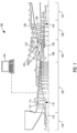
- FIG. 1 illustrates an example of a gas turbine engine 100 including a compressor section 102, a combustion section 104, and a turbine section 106 arranged along a central axis 112.
- the compressor section 102 includes a plurality of compressor stages 114 with each compressor stage 114 including a set of stationary compressor vane 116 or adjustable guide vanes and a set of rotating compressor blade 118.
- a rotor 134 supports the rotating compressor blade 118 for rotation about the central axis 112 during operation.
- a single one-piece rotor 134 extends the length of the gas turbine engine 100 and is supported for rotation by a bearing at either end.
- the rotor 134 is assembled from several separate spools that are attached to one another or may include multiple disk sections that are attached via a bolt or plurality of bolts.
- the compressor section 102 is in fluid communication with an inlet section 108 to allow the gas turbine engine 100 to draw atmospheric air into the compressor section 102. During operation of the gas turbine engine 100, the compressor section 102 draws in atmospheric air and compresses that air for delivery to the combustion section 104.
- the illustrated compressor section 102 is an example of one compressor section 102 with other arrangements and designs being possible.
- the combustion section 104 includes a plurality of separate combustors 120 that each operate to mix a flow of fuel with the compressed air from the compressor section 102 and to combust that air-fuel mixture to produce a flow of high temperature, high pressure combustion gases or exhaust gas 122.
- combustors 120 that each operate to mix a flow of fuel with the compressed air from the compressor section 102 and to combust that air-fuel mixture to produce a flow of high temperature, high pressure combustion gases or exhaust gas 122.
- many other arrangements of the combustion section 104 are possible.
- the turbine section 106 includes a plurality of turbine stages 124 with each turbine stage 124 including a number of stationary turbine vanes 126 and a number of rotating turbine blades 128.
- the turbine stages 124 are arranged to receive the exhaust gas 122 from the combustion section 104 at a turbine inlet 130 and expand that gas to convert thermal and pressure energy into rotating or mechanical work.
- the turbine section 106 is connected to the compressor section 102 to drive the compressor section 102.
- the turbine section 106 is also connected to a generator, pump, or other device to be driven.
- the compressor section 102 other designs and arrangements of the turbine section 106 are possible.
- An exhaust portion 110 is positioned downstream of the turbine section 106 and is arranged to receive the expanded flow of exhaust gas 122 from the final turbine stage 124 in the turbine section 106.
- the exhaust portion 110 is arranged to efficiently direct the exhaust gas 122 away from the turbine section 106 to assure efficient operation of the turbine section 106.
- Many variations and design differences are possible in the exhaust portion 110. As such, the illustrated exhaust portion 110 is but one example of those variations.
- a control system 132 is coupled to the gas turbine engine 100 and operates to monitor various operating parameters and to control various operations of the gas turbine engine 100.
- the control system 132 is typically micro-processor based and includes memory devices and data storage devices for collecting, analyzing, and storing data.
- the control system 132 provides output data to various devices including monitors, printers, indicators, and the like that allow users to interface with the control system 132 to provide inputs or adjustments.
- a user may input a power output set point and the control system 132 may adjust the various control inputs to achieve that power output in an efficient manner.
- the control system 132 can control various operating parameters including, but not limited to variable inlet guide vane positions, fuel flow rates and pressures, engine speed, valve positions, generator load, and generator excitation. Of course, other applications may have fewer or more controllable devices.
- the control system 132 also monitors various parameters to assure that the gas turbine engine 100 is operating properly. Some parameters that are monitored may include inlet air temperature, compressor outlet temperature and pressure, combustor outlet temperature, fuel flow rate, generator power output, bearing temperature, and the like. Many of these measurements are displayed for the user and are logged for later review should such a review be necessary.
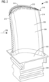
- FIG. 2 illustrates a perspective view of a turbine blade 200.
- the turbine blade 200 or similar blades may be used in the gas turbine engine 100 as the rotating turbine blades 128.
- the turbine blade 200 has a blade platform 202, a blade airfoil 300, and a blade root 204.
- the blade root 204 extends from a first side of the blade platform 202 toward the rotor 134 to engage the turbine blade 200 with the rotor 134.
- the blade airfoil 300 extends from a second side of the blade platform 202, which is opposite to the first side, toward a blade tip 216.
- the blade airfoil 300 has a pressure side wall 208 and a suction side wall 210 that join together at a blade leading edge 212 and a blade trailing edge 214 with respect to a flow direction of the working fluid 206.
- a mean camber line 218 of the blade airfoil 300 is defined from the blade leading edge 212 to the blade trailing edge 214 passing through a midway points between the pressure side wall 208 and the suction side wall 210.
- the blade airfoil 300 is exposed in a stream of working fluid 206.
- the working fluid 206 may include the exhaust gas 122 from the combustor 120 shown in FIG. 1 .
- FIG. 3 illustrates a portion of the perspective view of the turbine blade 200 shown in FIG. 2 that better illustrates the blade tip 216.
- the blade airfoil 300 has a tip cap surface 302 which is a surface at an end of the blade airfoil 300 facing the blade tip 216.
- the blade airfoil 300 has a first plurality of cooling holes 310 that are formed at the tip cap surface 302 and pass through the tip cap surface 302. The first plurality of cooling holes 310 are in flow connection with an interior of the blade airfoil 300.
- the blade airfoil 300 has an offset surface 308 that is offset a non-zero distance from the tip cap surface 302 toward the blade platform 202.
- the offset surface 308 is disposed at a region that is closer to the blade leading edge 212 than the blade trailing edge 214.
- the offset surface 308 may be parallel to the tip cap surface 302.
- the blade airfoil 300 may not have the offset surface 308 such that the tip cap surface 302 extends from the blade leading edge 212 to the blade trailing edge 214 and extends between the pressure side wall 208 and the suction side wall 210 at the end of the blade airfoil 300 facing the blade tip 216.
- the blade tip 216 include a so-called "squealer tip".
- the squealer tip is defined by a squealer tip wall 304 that extends along a portion of the pressure side wall 208 and a portion of the suction side wall 210 from the tip cap surface 302 to the blade tip 216 and from blade leading edge 212 toward the blade trailing edge 214.
- the squealer tip wall 304 includes a pressure side squealer tip wall 312 and a suction side squealer tip wall 314.
- the pressure side squealer tip wall 312 extends along a portion of the pressure side wall 208.
- the suction side squealer tip wall 314 extends along a portion of the suction side wall 210.
- the pressure side squealer tip wall 312 extends along the pressure side wall 208 from the blade leading edge 212 to a location before the blade trailing edge 214.
- the suction side squealer tip wall 314 extends along the suction side wall 210 from the blade leading edge 212 to the blade trailing edge 214.
- the pressure side squealer tip wall 312 may extends along the pressure side wall 208 from the blade leading edge 212 to the blade trailing edge 214 and/or the suction side squealer tip wall 314 may extends along the suction side wall 210 from the blade leading edge 212 to a location before the blade trailing edge 214.
- the blade airfoil 300 has a second plurality of cooling holes 318 that are formed at the squealer tip wall 304 and pass through the squealer tip wall 304.
- the second plurality of cooling holes 318 are arranged at the pressure side squealer tip wall 312 and pass through the pressure side squealer tip wall 312 and are arranged at the suction side squealer tip wall 314 and pass through the suction side squealer tip wall 314.
- the second plurality of cooling holes 318 are in flow connection with the interior of the blade airfoil 300.
- a chamfered surface 306 is formed as a part of the squealer tip wall 304.
- the portion of the squealer tip wall 304 that is adjacent to the blade trailing edge 214 is chamfered to form the chamfered surface 306.
- adjacent means that the chamfered surface 306 begins at the blade trailing edge 214 or within 10% of a length of the mean camber line 218 from the blade trailing edge 214.
- the chamfered surface 306 may extend along the squealer tip wall 304 from the blade trailing edge 214 toward the blade leading edge 212 for a distance between 1-30% of the length of the mean camber line 218.
- the length of the mean camber line 218 is defined as the curved length of the mean camber line 218 from the blade trailing edge 214 to the blade leading edge 212.
- the chamfered surface 306 may extend from the blade tip 216 toward the blade platform 202 for a distance between 1 - 5% of a height of the blade airfoil 300.
- the height of the blade airfoil 300 is defined from the blade platform 202 to the blade tip 216.
- the chamfered surface 306 may have any desired dimensions and orientations to meet design requirements of the gas turbine engine 100.
- the chamfered surface 306 is formed as a part of the suction side squealer tip wall 314. A portion of the suction side squealer tip wall 314 that is adjacent to the blade trailing edge 214 is chamfered to form the chamfered surface 306. The chamfered surface 306 extends along the suction side squealer tip wall 314 from the blade trailing edge 214 toward the blade leading edge 212 for the distance between 1-30% of the length of the mean camber line 218.
- the chamfered surface 306 extends from the blade tip 216 on the suction side squealer tip wall 314 toward the blade platform 202 for the distance between 1 - 5% of the height of the blade airfoil 300.
- the chamfered surface 306 may be formed as a part of the suction side squealer tip wall 314 and a part of the pressure side squealer tip wall 312 that are adjacent to the blade trailing edge 214.
- the chamfered surface 306 may be formed as a part of the squealer tip wall 304 adjacent to the blade trailing edge 214 of a blade airfoil 300 having the tip cap surface 302 extending from the blade leading edge 212 to the blade trailing edge 214 without the offset surface 308.
- a thermal barrier coating 316 is applied to the chamfered surface 306.
- the chamfered surface 306 may not be applied with the thermal barrier coating 316.
- cooling flow exits the blade airfoil 300 from the interior of the blade airfoil 300 through the first plurality of cooling holes 310 disposed at the tip cap surface 302 and through the second plurality of cooling holes 318 disposed at the squealer tip wall 304.
- the tip cap surface 302 is stepped radially up from the offset surface 308 so that the cooling flow exits the blade airfoil 300 at a location that is closer to the blade tip 216. Cooling to the blade tip 216 is thus improved.
- the chamfered surface 306 at the region of the blade trailing edge 214 of the squealer tip wall 304 reduces metal temperature of the blade airfoil 300 at this region.
- the chamfered surface 306 is coated with the thermal barrier coating 316.
- the arrangement of the chamfered surface 306 with the thermal barrier coating 316 reduces the degradation and distress at the trailing edge 214 of the squealer tip wall 304. Durability of the turbine blade 200 is thus improved.
Landscapes
- Engineering & Computer Science (AREA)
- Mechanical Engineering (AREA)
- General Engineering & Computer Science (AREA)
- Chemical & Material Sciences (AREA)
- Materials Engineering (AREA)
- Physics & Mathematics (AREA)
- Fluid Mechanics (AREA)
- Architecture (AREA)
- Turbine Rotor Nozzle Sealing (AREA)
Abstract
Description
- A gas turbine engine typically includes a compressor section, a turbine section, and a combustion section disposed therebetween. The compressor section includes multiple stages of rotating compressor blades and stationary compressor vanes. The combustion section typically includes a plurality of combustors. The turbine section includes multiple stages of rotating turbine blades and stationary turbine vanes. Turbine blades and turbine vanes often operate in a high temperature environment and are internally cooled.
- In one aspect, a turbine blade includes a blade platform, a blade airfoil that extends from the blade platform toward a blade tip, the blade airfoil having a pressure side wall and a suction side wall joined at a blade leading edge and a blade trailing edge, a tip cap surface defined at an end of the blade airfoil facing the blade tip, a squealer tip wall that extends along a portion of the pressure side wall and a portion of the suction side wall from the tip cap surface to the blade tip and from the blade leading edge toward the blade trailing edge, and a chamfered surface formed as a part of the squealer tip wall at a region that is adjacent to the blade trailing edge.
- In one aspect, a turbine blade includes a blade platform, a blade airfoil that extends from the blade platform toward a blade tip, the blade airfoil having a pressure side wall and a suction side wall joined at a blade leading edge and a blade trailing edge, a tip cap surface defined at an end of the blade airfoil facing the blade tip, a squealer tip wall includes a suction side squealer tip wall that extends along the suction side wall from the tip cap surface to the blade tip and from the blade leading edge to the blade trailing edge, and a chamfered surface formed as a part of the suction side squealer tip wall at a region that is adjacent to the blade trailing edge.
- To easily identify the discussion of any particular element or act, the most significant digit or digits in a reference number refer to the figure number in which that element is first introduced.
-
FIG. 1 is a longitudinal cross-sectional view of a gas turbine engine taken along a plane that contains a longitudinal axis or central axis. -
FIG. 2 is a perspective view of a turbine blade for use with the gas turbine engine shown inFIG. 1 . -
FIG. 3 is a portion of the perspective view of the turbine blade shown inFIG. 2 that better illustrates a blade tip. - Before any embodiments of the invention are explained in detail, it is to be understood that the invention is not limited in its application to the details of construction and the arrangement of components set forth in this description or illustrated in the following drawings. The invention is capable of other embodiments and of being practiced or of being carried out in various ways. Also, it is to be understood that the phraseology and terminology used herein is for the purpose of description and should not be regarded as limiting.
- Various technologies that pertain to systems and methods will now be described with reference to the drawings, where like reference numerals represent like elements throughout. The drawings discussed below, and the various embodiments used to describe the principles of the present disclosure in this patent document are by way of illustration only and should not be construed in any way to limit the scope of the disclosure. Those skilled in the art will understand that the principles of the present disclosure may be implemented in any suitably arranged apparatus. It is to be understood that functionality that is described as being carried out by certain system elements may be performed by multiple elements. Similarly, for instance, an element may be configured to perform functionality that is described as being carried out by multiple elements. The numerous innovative teachings of the present application will be described with reference to exemplary non-limiting embodiments.
- Also, it should be understood that the words or phrases used herein should be construed broadly, unless expressly limited in some examples. For example, the terms "including", "having", and "comprising", as well as derivatives thereof, mean inclusion without limitation. The singular forms "a", "an", and "the" are intended to include the plural forms as well, unless the context clearly indicates otherwise. Further, the term "and/or" as used herein refers to and encompasses any and all possible combinations of one or more of the associated listed items. The term "or" is inclusive, meaning and/or, unless the context clearly indicates otherwise. The phrases "associated with" and "associated therewith" as well as derivatives thereof, may mean to include, be included within, interconnect with, contain, be contained within, connect to or with, couple to or with, be communicable with, cooperate with, interleave, juxtapose, be proximate to, be bound to or with, have, have a property of, or the like. Furthermore, while multiple embodiments or constructions may be described herein, any features, methods, steps, components, etc. described with regard to one embodiment are equally applicable to other embodiments absent a specific statement to the contrary.
- Also, although the terms "first", "second", "third" and so forth may be used herein to refer to various elements, information, functions, or acts, these elements, information, functions, or acts should not be limited by these terms. Rather these numeral adjectives are used to distinguish different elements, information, functions or acts from each other. For example, a first element, information, function, or act could be termed a second element, information, function, or act, and, similarly, a second element, information, function, or act could be termed a first element, information, function, or act, without departing from the scope of the present disclosure.
- Also, in the description, the terms "axial" or "axially" refer to a direction along a longitudinal axis of a gas turbine engine. The terms "radial" or "radially" refer to a direction perpendicular to the longitudinal axis of the gas turbine engine. The terms "downstream" or "aft" refer to a direction along a flow direction. The terms "upstream" or "forward" refer to a direction against the flow direction.
- In addition, the term "adjacent to" may mean that an element is relatively near to but not in contact with a further element or that the element is in contact with the further portion, unless the context clearly indicates otherwise. Further, the phrase "based on" is intended to mean "based, at least in part, on" unless explicitly stated otherwise. Terms "about" or "substantially" or like terms are intended to cover variations in a value that are within normal industry manufacturing tolerances for that dimension. If no industry standard is available, a variation of twenty percent would fall within the meaning of these terms unless otherwise stated.
-
FIG. 1 illustrates an example of agas turbine engine 100 including acompressor section 102, acombustion section 104, and aturbine section 106 arranged along acentral axis 112. Thecompressor section 102 includes a plurality ofcompressor stages 114 with eachcompressor stage 114 including a set ofstationary compressor vane 116 or adjustable guide vanes and a set of rotatingcompressor blade 118. Arotor 134 supports the rotatingcompressor blade 118 for rotation about thecentral axis 112 during operation. In some constructions, a single one-piece rotor 134 extends the length of thegas turbine engine 100 and is supported for rotation by a bearing at either end. In other constructions, therotor 134 is assembled from several separate spools that are attached to one another or may include multiple disk sections that are attached via a bolt or plurality of bolts. - The
compressor section 102 is in fluid communication with aninlet section 108 to allow thegas turbine engine 100 to draw atmospheric air into thecompressor section 102. During operation of thegas turbine engine 100, thecompressor section 102 draws in atmospheric air and compresses that air for delivery to thecombustion section 104. The illustratedcompressor section 102 is an example of onecompressor section 102 with other arrangements and designs being possible. - In the illustrated construction, the
combustion section 104 includes a plurality ofseparate combustors 120 that each operate to mix a flow of fuel with the compressed air from thecompressor section 102 and to combust that air-fuel mixture to produce a flow of high temperature, high pressure combustion gases orexhaust gas 122. Of course, many other arrangements of thecombustion section 104 are possible. - The
turbine section 106 includes a plurality ofturbine stages 124 with eachturbine stage 124 including a number ofstationary turbine vanes 126 and a number of rotatingturbine blades 128. Theturbine stages 124 are arranged to receive theexhaust gas 122 from thecombustion section 104 at aturbine inlet 130 and expand that gas to convert thermal and pressure energy into rotating or mechanical work. Theturbine section 106 is connected to thecompressor section 102 to drive thecompressor section 102. Forgas turbine engines 100 used for power generation or as prime movers, theturbine section 106 is also connected to a generator, pump, or other device to be driven. As with thecompressor section 102, other designs and arrangements of theturbine section 106 are possible. - An
exhaust portion 110 is positioned downstream of theturbine section 106 and is arranged to receive the expanded flow ofexhaust gas 122 from thefinal turbine stage 124 in theturbine section 106. Theexhaust portion 110 is arranged to efficiently direct theexhaust gas 122 away from theturbine section 106 to assure efficient operation of theturbine section 106. Many variations and design differences are possible in theexhaust portion 110. As such, the illustratedexhaust portion 110 is but one example of those variations. - A
control system 132 is coupled to thegas turbine engine 100 and operates to monitor various operating parameters and to control various operations of thegas turbine engine 100. In preferred constructions thecontrol system 132 is typically micro-processor based and includes memory devices and data storage devices for collecting, analyzing, and storing data. In addition, thecontrol system 132 provides output data to various devices including monitors, printers, indicators, and the like that allow users to interface with thecontrol system 132 to provide inputs or adjustments. In the example of a power generation system, a user may input a power output set point and thecontrol system 132 may adjust the various control inputs to achieve that power output in an efficient manner. - The
control system 132 can control various operating parameters including, but not limited to variable inlet guide vane positions, fuel flow rates and pressures, engine speed, valve positions, generator load, and generator excitation. Of course, other applications may have fewer or more controllable devices. Thecontrol system 132 also monitors various parameters to assure that thegas turbine engine 100 is operating properly. Some parameters that are monitored may include inlet air temperature, compressor outlet temperature and pressure, combustor outlet temperature, fuel flow rate, generator power output, bearing temperature, and the like. Many of these measurements are displayed for the user and are logged for later review should such a review be necessary. -
FIG. 2 illustrates a perspective view of aturbine blade 200. Theturbine blade 200 or similar blades may be used in thegas turbine engine 100 as the rotatingturbine blades 128. - The
turbine blade 200 has ablade platform 202, ablade airfoil 300, and ablade root 204. Theblade root 204 extends from a first side of theblade platform 202 toward therotor 134 to engage theturbine blade 200 with therotor 134. - The
blade airfoil 300 extends from a second side of theblade platform 202, which is opposite to the first side, toward ablade tip 216. Theblade airfoil 300 has apressure side wall 208 and asuction side wall 210 that join together at ablade leading edge 212 and ablade trailing edge 214 with respect to a flow direction of the workingfluid 206. Amean camber line 218 of theblade airfoil 300 is defined from theblade leading edge 212 to theblade trailing edge 214 passing through a midway points between thepressure side wall 208 and thesuction side wall 210. Theblade airfoil 300 is exposed in a stream of workingfluid 206. The workingfluid 206 may include theexhaust gas 122 from thecombustor 120 shown inFIG. 1 . -
FIG. 3 illustrates a portion of the perspective view of theturbine blade 200 shown inFIG. 2 that better illustrates theblade tip 216. Theblade airfoil 300 has atip cap surface 302 which is a surface at an end of theblade airfoil 300 facing theblade tip 216. Theblade airfoil 300 has a first plurality ofcooling holes 310 that are formed at thetip cap surface 302 and pass through thetip cap surface 302. The first plurality ofcooling holes 310 are in flow connection with an interior of theblade airfoil 300. Theblade airfoil 300 has an offsetsurface 308 that is offset a non-zero distance from thetip cap surface 302 toward theblade platform 202. The offsetsurface 308 is disposed at a region that is closer to theblade leading edge 212 than theblade trailing edge 214. The offsetsurface 308 may be parallel to thetip cap surface 302. In other constructions, theblade airfoil 300 may not have the offsetsurface 308 such that thetip cap surface 302 extends from theblade leading edge 212 to theblade trailing edge 214 and extends between thepressure side wall 208 and thesuction side wall 210 at the end of theblade airfoil 300 facing theblade tip 216. - The
blade tip 216 include a so-called "squealer tip". The squealer tip is defined by asquealer tip wall 304 that extends along a portion of thepressure side wall 208 and a portion of thesuction side wall 210 from thetip cap surface 302 to theblade tip 216 and fromblade leading edge 212 toward theblade trailing edge 214. Thesquealer tip wall 304 includes a pressure sidesquealer tip wall 312 and a suction sidesquealer tip wall 314. The pressure sidesquealer tip wall 312 extends along a portion of thepressure side wall 208. The suction sidesquealer tip wall 314 extends along a portion of thesuction side wall 210. In the construction illustrated inFIG. 3 , the pressure sidesquealer tip wall 312 extends along thepressure side wall 208 from theblade leading edge 212 to a location before theblade trailing edge 214. The suction sidesquealer tip wall 314 extends along thesuction side wall 210 from theblade leading edge 212 to theblade trailing edge 214. In other constructions, the pressure sidesquealer tip wall 312 may extends along thepressure side wall 208 from theblade leading edge 212 to theblade trailing edge 214 and/or the suction sidesquealer tip wall 314 may extends along thesuction side wall 210 from theblade leading edge 212 to a location before theblade trailing edge 214. - The
blade airfoil 300 has a second plurality ofcooling holes 318 that are formed at thesquealer tip wall 304 and pass through thesquealer tip wall 304. The second plurality ofcooling holes 318 are arranged at the pressure sidesquealer tip wall 312 and pass through the pressure sidesquealer tip wall 312 and are arranged at the suction sidesquealer tip wall 314 and pass through the suction sidesquealer tip wall 314. The second plurality ofcooling holes 318 are in flow connection with the interior of theblade airfoil 300. - A
chamfered surface 306 is formed as a part of thesquealer tip wall 304. In the construction illustrated inFIG. 3 , the portion of thesquealer tip wall 304 that is adjacent to theblade trailing edge 214 is chamfered to form the chamferedsurface 306. As used herein "adjacent" means that the chamferedsurface 306 begins at theblade trailing edge 214 or within 10% of a length of themean camber line 218 from theblade trailing edge 214. The chamferedsurface 306 may extend along thesquealer tip wall 304 from theblade trailing edge 214 toward theblade leading edge 212 for a distance between 1-30% of the length of themean camber line 218. The length of themean camber line 218 is defined as the curved length of themean camber line 218 from theblade trailing edge 214 to theblade leading edge 212. The chamferedsurface 306 may extend from theblade tip 216 toward theblade platform 202 for a distance between 1 - 5% of a height of theblade airfoil 300. The height of theblade airfoil 300 is defined from theblade platform 202 to theblade tip 216. The chamferedsurface 306 may have any desired dimensions and orientations to meet design requirements of thegas turbine engine 100. - In the construction illustrated in
FIG. 3 , the chamferedsurface 306 is formed as a part of the suction sidesquealer tip wall 314. A portion of the suction sidesquealer tip wall 314 that is adjacent to theblade trailing edge 214 is chamfered to form the chamferedsurface 306. The chamferedsurface 306 extends along the suction sidesquealer tip wall 314 from theblade trailing edge 214 toward theblade leading edge 212 for the distance between 1-30% of the length of themean camber line 218. The chamferedsurface 306 extends from theblade tip 216 on the suction sidesquealer tip wall 314 toward theblade platform 202 for the distance between 1 - 5% of the height of theblade airfoil 300. In other constructions, the chamferedsurface 306 may be formed as a part of the suction sidesquealer tip wall 314 and a part of the pressure sidesquealer tip wall 312 that are adjacent to theblade trailing edge 214. In yet other constructions, the chamferedsurface 306 may be formed as a part of thesquealer tip wall 304 adjacent to theblade trailing edge 214 of ablade airfoil 300 having thetip cap surface 302 extending from theblade leading edge 212 to theblade trailing edge 214 without the offsetsurface 308. - A
thermal barrier coating 316 is applied to the chamferedsurface 306. In other constructions, the chamferedsurface 306 may not be applied with thethermal barrier coating 316. - In operation, with reference to
FIG. 2 andFIG. 3 , cooling flow exits theblade airfoil 300 from the interior of theblade airfoil 300 through the first plurality ofcooling holes 310 disposed at thetip cap surface 302 and through the second plurality ofcooling holes 318 disposed at thesquealer tip wall 304. Thetip cap surface 302 is stepped radially up from the offsetsurface 308 so that the cooling flow exits theblade airfoil 300 at a location that is closer to theblade tip 216. Cooling to theblade tip 216 is thus improved. The chamferedsurface 306 at the region of theblade trailing edge 214 of thesquealer tip wall 304 reduces metal temperature of theblade airfoil 300 at this region. The chamferedsurface 306 is coated with thethermal barrier coating 316. The arrangement of the chamferedsurface 306 with thethermal barrier coating 316 reduces the degradation and distress at the trailingedge 214 of thesquealer tip wall 304. Durability of theturbine blade 200 is thus improved. - Although an exemplary embodiment of the present disclosure has been described in detail, those skilled in the art will understand that various changes, substitutions, variations, and improvements disclosed herein may be made without departing from the spirit and scope of the disclosure in its broadest form.
- None of the description in the present application should be read as implying that any particular element, step, act, or function is an essential element, which must be included in the claim scope: the scope of patented subject matter is defined only by the allowed claims. Moreover, none of these claims are intended to invoke a means plus function claim construction unless the exact words "means for" are followed by a participle.
- Further Embodiments
- 1. A turbine blade (200) comprising:
- a blade platform (202);
- a blade airfoil (300) that extends from the blade platform (202) toward a blade tip (216), the blade airfoil (300) having a pressure side wall (208) and a suction side wall (210) joined at a blade leading edge (212) and a blade trailing edge (214);
- a tip cap surface (302) defined at an end of the blade airfoil (300) facing the blade tip (216);
- a squealer tip wall (304) that extends along a portion of the pressure side wall (208) and a portion of the suction side wall (210) from the tip cap surface (302) to the blade tip (216) and from the blade leading edge (212) toward the blade trailing edge (214); and
- a chamfered surface (306) formed as a part of the squealer tip wall (304) at a region that is adjacent to the blade trailing edge (214).
- 2. The turbine blade (200) of embodiment 1, wherein the chamfered surface (306) extends along the squealer tip wall (304) from the blade trailing edge (214) toward the blade leading edge (212) for a distance between 1 - 30% of a length of a mean camber line (218) of the blade airfoil (300).
- 3. The turbine blade (200) of embodiment 1, wherein the chamfered surface (306) extends from a blade tip (216) toward the blade platform (202) for a distance between 1 -5% of a height of the blade airfoil (300).
- 4. The turbine blade (200) of embodiment 1, wherein a thermal barrier coating (316) is applied to the chamfered surface (306).
- 5. The turbine blade (200) of embodiment 1, wherein the squealer tip wall (304) comprises a pressure side squealer tip wall (312) that extends along the pressure side wall (208) from the blade leading edge (212) to a location before the blade trailing edge (214).
- 6. The turbine blade (200) of embodiment 1, wherein the squealer tip wall (304) comprises a suction side squealer tip wall (314) that extends along the suction side wall (210) from the blade leading edge (212) to the blade trailing edge (214).
- 7. The turbine blade (200) of embodiment 6, wherein the chamfered surface (306) is formed as a part of the suction side squealer tip wall (314).
- 8. The turbine blade (200) of embodiment 1, further comprising an offset surface (308) that is offset a non-zero distance from the tip cap surface (302) toward the blade platform (202).
- 9. The turbine blade (200) of embodiment 8, wherein the offset surface (308) is disposed at a region that is closer to the blade leading edge (212) than the blade trailing edge (214).
- 10. The turbine blade (200) of embodiment 1, wherein a first plurality of cooling holes (310) are arranged at the tip cap surface (302) and pass through the tip cap surface (302).
- 11. The turbine blade (200) of embodiment 1, wherein a second plurality of cooling holes (318) are arranged at the squealer tip wall (304) and pass through the squealer tip wall (304).
-
- 100: gas turbine engine
- 102: compressor section
- 104: combustion section
- 106: turbine section
- 108: inlet section
- 110: exhaust portion
- 112: central axis
- 114: compressor stage
- 116: stationary compressor vane
- 118: rotating compressor blade
- 120: combustor
- 122: exhaust gas
- 124: turbine stage
- 126: stationary turbine vane
- 128: rotating turbine blade
- 130: turbine inlet
- 132: control system
- 134: rotor
- 200: turbine blade
- 202: blade platform
- 204: blade root
- 206: working fluid
- 208: pressure side wall
- 210: suction side wall
- 212: blade leading edge
- 214: blade trailing edge
- 216: blade tip
- 218: mean camber line
- 300: blade airfoil
- 302: tip cap surface
- 304: squealer tip wall
- 306: chamfered surface
- 308: offset surface
- 310: cooling hole
- 312: pressure side squealer tip wall
- 314: suction side squealer tip wall
- 316: thermal barrier coating
- 318: cooling hole
Claims (11)
- A turbine blade (200) comprising:a blade platform (202);a blade airfoil (300) that extends from the blade platform (202) toward a blade tip (216), the blade airfoil (300) having a pressure side wall (208) and a suction side wall (210) joined at a blade leading edge (212) and a blade trailing edge (214);a tip cap surface (302) defined at an end of the blade airfoil (300) facing the blade tip (216);a squealer tip wall (304) that extends along a portion of the pressure side wall (208) and a portion of the suction side wall (210) from the tip cap surface (302) to the blade tip (216) and from the blade leading edge (212) toward the blade trailing edge (214); anda chamfered surface (306) formed as a part of the squealer tip wall (304) at a region that is adjacent to the blade trailing edge (214).
- The turbine blade of claim 1, wherein the chamfered surface (306) extends along the squealer tip wall (304) from the blade trailing edge (214) toward the blade leading edge (212) for a distance between 1 - 30% of a length of a mean camber line (218) of the blade airfoil (300).
- The turbine bladeaccording to any of the preceding claims, wherein the chamfered surface (306) extends from a blade tip (216) toward the blade platform (202) for a distance between 1 -5% of a height of the blade airfoil (300).
- The turbine blade according to any of the preceding claims, wherein a thermal barrier coating (316) is applied to the chamfered surface (306).
- The turbine blade according to any of the preceding claims, wherein the squealer tip wall (304) comprises a pressure side squealer tip wall (312) that extends along the pressure side wall (208) from the blade leading edge (212) to a location before the blade trailing edge (214).
- The turbine blade according to any of the preceding claims, wherein the squealer tip wall (304) comprises a suction side squealer tip wall (314) that extends along the suction side wall (210) from the blade leading edge (212) to the blade trailing edge (214).
- The turbine blade of claim 6, wherein the chamfered surface (306) is formed as a part of the suction side squealer tip wall (314).
- The turbine blade according to any of the preceding claims, further comprising an offset surface (308) that is offset a non-zero distance from the tip cap surface (302) toward the blade platform (202).
- The turbine blade of claim 8, wherein the offset surface (308) is disposed at a region that is closer to the blade leading edge (212) than the blade trailing edge (214).
- The turbine blade according to any of the preceding claims, wherein a first plurality of cooling holes (310) are arranged at the tip cap surface (302) and pass through the tip cap surface (302).
- The turbine blade according to any of the preceding claims, wherein a second plurality of cooling holes (318) are arranged at the squealer tip wall (304) and pass through the squealer tip wall (304).
Applications Claiming Priority (1)
| Application Number | Priority Date | Filing Date | Title |
|---|---|---|---|
| US202263369391P | 2022-07-26 | 2022-07-26 |
Publications (2)
| Publication Number | Publication Date |
|---|---|
| EP4311914A1 true EP4311914A1 (en) | 2024-01-31 |
| EP4311914B1 EP4311914B1 (en) | 2025-05-07 |
Family
ID=86646617
Family Applications (1)
| Application Number | Title | Priority Date | Filing Date |
|---|---|---|---|
| EP23176408.5A Active EP4311914B1 (en) | 2022-07-26 | 2023-05-31 | Turbine blade |
Country Status (3)
| Country | Link |
|---|---|
| US (1) | US12173617B2 (en) |
| EP (1) | EP4311914B1 (en) |
| CN (1) | CN117449914A (en) |
Cited By (1)
| Publication number | Priority date | Publication date | Assignee | Title |
|---|---|---|---|---|
| US20250188843A1 (en) * | 2022-08-24 | 2025-06-12 | General Electric Company | Turbine engine airfoil |
Families Citing this family (1)
| Publication number | Priority date | Publication date | Assignee | Title |
|---|---|---|---|---|
| US12680456B1 (en) * | 2025-03-12 | 2026-07-14 | Rtx Corporation | Turbine blade for a gas turbine engine and method for forming same |
Citations (6)
| Publication number | Priority date | Publication date | Assignee | Title |
|---|---|---|---|---|
| DE19944923A1 (en) * | 1999-09-20 | 2001-03-22 | Asea Brown Boveri | Turbine blade for rotor of gas turbine; has blade crown with cap having bars and hollow spaces inside bars connected to cooling channels to supply cooling air to inside of bars |
| US20040151586A1 (en) * | 2003-01-31 | 2004-08-05 | Chlus Wieslaw A. | Turbine blade |
| CN104775854A (en) * | 2015-04-23 | 2015-07-15 | 华能国际电力股份有限公司 | A rotor blade top structure capable of suppressing blade top leakage and reducing blade top temperature |
| US20170226866A1 (en) * | 2014-11-20 | 2017-08-10 | Mitsubishi Heavy Industries, Ltd. | Turbine blade and gas turbine |
| US20210340877A1 (en) * | 2018-12-06 | 2021-11-04 | Mitsubishi Power, Ltd. | Turbine rotor blade, turbine, and tip clearance measurement method |
| US20220170374A1 (en) * | 2020-11-13 | 2022-06-02 | Doosan Heavy Industries & Construction Co., Ltd. | Trailing edge tip cooling of blade of a gas turbine blade |
Family Cites Families (11)
| Publication number | Priority date | Publication date | Assignee | Title |
|---|---|---|---|---|
| US7281894B2 (en) | 2005-09-09 | 2007-10-16 | General Electric Company | Turbine airfoil curved squealer tip with tip shelf |
| JP5031103B2 (en) * | 2008-10-30 | 2012-09-19 | 三菱重工業株式会社 | Turbine blades with tip thinning |
| US8157504B2 (en) * | 2009-04-17 | 2012-04-17 | General Electric Company | Rotor blades for turbine engines |
| US8684691B2 (en) * | 2011-05-03 | 2014-04-01 | Siemens Energy, Inc. | Turbine blade with chamfered squealer tip and convective cooling holes |
| US20130104397A1 (en) * | 2011-10-28 | 2013-05-02 | General Electric Company | Methods for repairing turbine blade tips |
| US10012089B2 (en) * | 2014-05-16 | 2018-07-03 | United Technologies Corporation | Airfoil tip pocket with augmentation features |
| EP3247883A1 (en) * | 2015-01-22 | 2017-11-29 | Siemens Energy, Inc. | Turbine airfoil cooling system with chordwise extending squealer tip cooling channel |
| WO2019035802A1 (en) * | 2017-08-14 | 2019-02-21 | Siemens Aktiengesellschaft | Turbine blade and corresponding method of servicing |
| KR102319765B1 (en) * | 2018-02-09 | 2021-11-01 | 두산중공업 주식회사 | Gas turbine |
| US11299991B2 (en) * | 2020-04-16 | 2022-04-12 | General Electric Company | Tip squealer configurations |
| EP3974618B1 (en) * | 2020-09-24 | 2023-04-19 | Doosan Enerbility Co., Ltd. | A technique for cooling squealer tip of a gas turbine blade |
-
2023
- 2023-05-31 EP EP23176408.5A patent/EP4311914B1/en active Active
- 2023-06-20 US US18/337,533 patent/US12173617B2/en active Active
- 2023-07-26 CN CN202310931900.7A patent/CN117449914A/en active Pending
Patent Citations (6)
| Publication number | Priority date | Publication date | Assignee | Title |
|---|---|---|---|---|
| DE19944923A1 (en) * | 1999-09-20 | 2001-03-22 | Asea Brown Boveri | Turbine blade for rotor of gas turbine; has blade crown with cap having bars and hollow spaces inside bars connected to cooling channels to supply cooling air to inside of bars |
| US20040151586A1 (en) * | 2003-01-31 | 2004-08-05 | Chlus Wieslaw A. | Turbine blade |
| US20170226866A1 (en) * | 2014-11-20 | 2017-08-10 | Mitsubishi Heavy Industries, Ltd. | Turbine blade and gas turbine |
| CN104775854A (en) * | 2015-04-23 | 2015-07-15 | 华能国际电力股份有限公司 | A rotor blade top structure capable of suppressing blade top leakage and reducing blade top temperature |
| US20210340877A1 (en) * | 2018-12-06 | 2021-11-04 | Mitsubishi Power, Ltd. | Turbine rotor blade, turbine, and tip clearance measurement method |
| US20220170374A1 (en) * | 2020-11-13 | 2022-06-02 | Doosan Heavy Industries & Construction Co., Ltd. | Trailing edge tip cooling of blade of a gas turbine blade |
Cited By (2)
| Publication number | Priority date | Publication date | Assignee | Title |
|---|---|---|---|---|
| US20250188843A1 (en) * | 2022-08-24 | 2025-06-12 | General Electric Company | Turbine engine airfoil |
| US12650079B2 (en) * | 2022-08-24 | 2026-06-09 | General Electric Company | Turbine engine airfoil |
Also Published As
| Publication number | Publication date |
|---|---|
| US20240035386A1 (en) | 2024-02-01 |
| US12173617B2 (en) | 2024-12-24 |
| EP4311914B1 (en) | 2025-05-07 |
| CN117449914A (en) | 2024-01-26 |
Similar Documents
| Publication | Publication Date | Title |
|---|---|---|
| US12173617B2 (en) | Turbine blade squealer tip wall with chamfered surface | |
| US8251668B2 (en) | Method and apparatus for assembling rotating machines | |
| US11761339B2 (en) | Turbine blade | |
| US20250198305A1 (en) | Gas turbine engine with turbine vane carrier cooling flow path | |
| EP4189215B1 (en) | Guide vane for a gas turbine engine | |
| US20230313697A1 (en) | Guide vane in gas turbine engine | |
| US12116906B2 (en) | Turbine vane in gas turbine engine | |
| EP4592497A1 (en) | Heat cover for rotor of gas turbine engine | |
| US20250215802A1 (en) | Locking spacer assemblies and method for installing a locking spacer assembly | |
| US11873733B2 (en) | Turbine blade in gas turbine engine | |
| EP4273366A1 (en) | Turbine component having platform cooling circuit | |
| EP4520921A1 (en) | Turbine component for gas turbine engine | |
| EP4343119A1 (en) | Ring segment for gas turbine engine | |
| US12044142B2 (en) | Gas turbine blade | |
| WO2025093157A1 (en) | Seal assembly for gas turbine engine | |
| WO2022051760A1 (en) | Guide vane in gas turbine engine | |
| US20230107877A1 (en) | Gas turbine engine stationary vane with contoured platform | |
| WO2024186457A1 (en) | Ring segment for gas turbine engine |
Legal Events
| Date | Code | Title | Description |
|---|---|---|---|
| PUAI | Public reference made under article 153(3) epc to a published international application that has entered the european phase |
Free format text: ORIGINAL CODE: 0009012 |
|
| STAA | Information on the status of an ep patent application or granted ep patent |
Free format text: STATUS: THE APPLICATION HAS BEEN PUBLISHED |
|
| AK | Designated contracting states |
Kind code of ref document: A1 Designated state(s): AL AT BE BG CH CY CZ DE DK EE ES FI FR GB GR HR HU IE IS IT LI LT LU LV MC ME MK MT NL NO PL PT RO RS SE SI SK SM TR |
|
| STAA | Information on the status of an ep patent application or granted ep patent |
Free format text: STATUS: REQUEST FOR EXAMINATION WAS MADE |
|
| 17P | Request for examination filed |
Effective date: 20240626 |
|
| RBV | Designated contracting states (corrected) |
Designated state(s): AL AT BE BG CH CY CZ DE DK EE ES FI FR GB GR HR HU IE IS IT LI LT LU LV MC ME MK MT NL NO PL PT RO RS SE SI SK SM TR |
|
| GRAP | Despatch of communication of intention to grant a patent |
Free format text: ORIGINAL CODE: EPIDOSNIGR1 |
|
| STAA | Information on the status of an ep patent application or granted ep patent |
Free format text: STATUS: GRANT OF PATENT IS INTENDED |
|
| RIC1 | Information provided on ipc code assigned before grant |
Ipc: F01D 5/28 20060101ALN20250123BHEP Ipc: F01D 5/20 20060101AFI20250123BHEP |
|
| RIC1 | Information provided on ipc code assigned before grant |
Ipc: F01D 5/28 20060101ALN20250127BHEP Ipc: F01D 5/20 20060101AFI20250127BHEP |
|
| INTG | Intention to grant announced |
Effective date: 20250213 |
|
| GRAS | Grant fee paid |
Free format text: ORIGINAL CODE: EPIDOSNIGR3 |
|
| GRAA | (expected) grant |
Free format text: ORIGINAL CODE: 0009210 |
|
| STAA | Information on the status of an ep patent application or granted ep patent |
Free format text: STATUS: THE PATENT HAS BEEN GRANTED |
|
| AK | Designated contracting states |
Kind code of ref document: B1 Designated state(s): AL AT BE BG CH CY CZ DE DK EE ES FI FR GB GR HR HU IE IS IT LI LT LU LV MC ME MK MT NL NO PL PT RO RS SE SI SK SM TR |
|
| REG | Reference to a national code |
Ref country code: GB Ref legal event code: FG4D |
|
| REG | Reference to a national code |
Ref country code: CH Ref legal event code: EP |
|
| REG | Reference to a national code |
Ref country code: DE Ref legal event code: R096 Ref document number: 602023003312 Country of ref document: DE |
|
| REG | Reference to a national code |
Ref country code: IE Ref legal event code: FG4D |
|
| REG | Reference to a national code |
Ref country code: NL Ref legal event code: MP Effective date: 20250507 |
|
| PG25 | Lapsed in a contracting state [announced via postgrant information from national office to epo] |
Ref country code: FI Free format text: LAPSE BECAUSE OF FAILURE TO SUBMIT A TRANSLATION OF THE DESCRIPTION OR TO PAY THE FEE WITHIN THE PRESCRIBED TIME-LIMIT Effective date: 20250507 Ref country code: PT Free format text: LAPSE BECAUSE OF FAILURE TO SUBMIT A TRANSLATION OF THE DESCRIPTION OR TO PAY THE FEE WITHIN THE PRESCRIBED TIME-LIMIT Effective date: 20250908 Ref country code: ES Free format text: LAPSE BECAUSE OF FAILURE TO SUBMIT A TRANSLATION OF THE DESCRIPTION OR TO PAY THE FEE WITHIN THE PRESCRIBED TIME-LIMIT Effective date: 20250507 |
|
| REG | Reference to a national code |
Ref country code: LT Ref legal event code: MG9D |
|
| PG25 | Lapsed in a contracting state [announced via postgrant information from national office to epo] |
Ref country code: NO Free format text: LAPSE BECAUSE OF FAILURE TO SUBMIT A TRANSLATION OF THE DESCRIPTION OR TO PAY THE FEE WITHIN THE PRESCRIBED TIME-LIMIT Effective date: 20250807 Ref country code: GR Free format text: LAPSE BECAUSE OF FAILURE TO SUBMIT A TRANSLATION OF THE DESCRIPTION OR TO PAY THE FEE WITHIN THE PRESCRIBED TIME-LIMIT Effective date: 20250808 |
|
| PG25 | Lapsed in a contracting state [announced via postgrant information from national office to epo] |
Ref country code: NL Free format text: LAPSE BECAUSE OF FAILURE TO SUBMIT A TRANSLATION OF THE DESCRIPTION OR TO PAY THE FEE WITHIN THE PRESCRIBED TIME-LIMIT Effective date: 20250507 Ref country code: PL Free format text: LAPSE BECAUSE OF FAILURE TO SUBMIT A TRANSLATION OF THE DESCRIPTION OR TO PAY THE FEE WITHIN THE PRESCRIBED TIME-LIMIT Effective date: 20250507 |
|
| REG | Reference to a national code |
Ref country code: AT Ref legal event code: MK05 Ref document number: 1792659 Country of ref document: AT Kind code of ref document: T Effective date: 20250507 |
|
| PG25 | Lapsed in a contracting state [announced via postgrant information from national office to epo] |
Ref country code: BG Free format text: LAPSE BECAUSE OF FAILURE TO SUBMIT A TRANSLATION OF THE DESCRIPTION OR TO PAY THE FEE WITHIN THE PRESCRIBED TIME-LIMIT Effective date: 20250507 |
|
| PG25 | Lapsed in a contracting state [announced via postgrant information from national office to epo] |
Ref country code: HR Free format text: LAPSE BECAUSE OF FAILURE TO SUBMIT A TRANSLATION OF THE DESCRIPTION OR TO PAY THE FEE WITHIN THE PRESCRIBED TIME-LIMIT Effective date: 20250507 |
|
| PG25 | Lapsed in a contracting state [announced via postgrant information from national office to epo] |
Ref country code: AT Free format text: LAPSE BECAUSE OF FAILURE TO SUBMIT A TRANSLATION OF THE DESCRIPTION OR TO PAY THE FEE WITHIN THE PRESCRIBED TIME-LIMIT Effective date: 20250507 |
|
| PG25 | Lapsed in a contracting state [announced via postgrant information from national office to epo] |
Ref country code: RS Free format text: LAPSE BECAUSE OF FAILURE TO SUBMIT A TRANSLATION OF THE DESCRIPTION OR TO PAY THE FEE WITHIN THE PRESCRIBED TIME-LIMIT Effective date: 20250807 |
|
| PG25 | Lapsed in a contracting state [announced via postgrant information from national office to epo] |
Ref country code: IS Free format text: LAPSE BECAUSE OF FAILURE TO SUBMIT A TRANSLATION OF THE DESCRIPTION OR TO PAY THE FEE WITHIN THE PRESCRIBED TIME-LIMIT Effective date: 20250907 |
|
| PG25 | Lapsed in a contracting state [announced via postgrant information from national office to epo] |
Ref country code: LV Free format text: LAPSE BECAUSE OF FAILURE TO SUBMIT A TRANSLATION OF THE DESCRIPTION OR TO PAY THE FEE WITHIN THE PRESCRIBED TIME-LIMIT Effective date: 20250507 |
|
| PG25 | Lapsed in a contracting state [announced via postgrant information from national office to epo] |
Ref country code: DK Free format text: LAPSE BECAUSE OF FAILURE TO SUBMIT A TRANSLATION OF THE DESCRIPTION OR TO PAY THE FEE WITHIN THE PRESCRIBED TIME-LIMIT Effective date: 20250507 Ref country code: SM Free format text: LAPSE BECAUSE OF FAILURE TO SUBMIT A TRANSLATION OF THE DESCRIPTION OR TO PAY THE FEE WITHIN THE PRESCRIBED TIME-LIMIT Effective date: 20250507 |
|
| PG25 | Lapsed in a contracting state [announced via postgrant information from national office to epo] |
Ref country code: LU Free format text: LAPSE BECAUSE OF NON-PAYMENT OF DUE FEES Effective date: 20250531 |
|
| PG25 | Lapsed in a contracting state [announced via postgrant information from national office to epo] |
Ref country code: CZ Free format text: LAPSE BECAUSE OF FAILURE TO SUBMIT A TRANSLATION OF THE DESCRIPTION OR TO PAY THE FEE WITHIN THE PRESCRIBED TIME-LIMIT Effective date: 20250507 |
|
| PG25 | Lapsed in a contracting state [announced via postgrant information from national office to epo] |
Ref country code: EE Free format text: LAPSE BECAUSE OF FAILURE TO SUBMIT A TRANSLATION OF THE DESCRIPTION OR TO PAY THE FEE WITHIN THE PRESCRIBED TIME-LIMIT Effective date: 20250507 |
|
| PG25 | Lapsed in a contracting state [announced via postgrant information from national office to epo] |
Ref country code: SK Free format text: LAPSE BECAUSE OF FAILURE TO SUBMIT A TRANSLATION OF THE DESCRIPTION OR TO PAY THE FEE WITHIN THE PRESCRIBED TIME-LIMIT Effective date: 20250507 |
|
| REG | Reference to a national code |
Ref country code: BE Ref legal event code: MM Effective date: 20250531 |
|
| REG | Reference to a national code |
Ref country code: DE Ref legal event code: R097 Ref document number: 602023003312 Country of ref document: DE |
|
| PG25 | Lapsed in a contracting state [announced via postgrant information from national office to epo] |
Ref country code: MC Free format text: LAPSE BECAUSE OF FAILURE TO SUBMIT A TRANSLATION OF THE DESCRIPTION OR TO PAY THE FEE WITHIN THE PRESCRIBED TIME-LIMIT Effective date: 20250507 |
|
| PG25 | Lapsed in a contracting state [announced via postgrant information from national office to epo] |
Ref country code: RO Free format text: LAPSE BECAUSE OF FAILURE TO SUBMIT A TRANSLATION OF THE DESCRIPTION OR TO PAY THE FEE WITHIN THE PRESCRIBED TIME-LIMIT Effective date: 20250507 |
|
| PLBE | No opposition filed within time limit |
Free format text: ORIGINAL CODE: 0009261 |
|
| STAA | Information on the status of an ep patent application or granted ep patent |
Free format text: STATUS: NO OPPOSITION FILED WITHIN TIME LIMIT |
|
| REG | Reference to a national code |
Ref country code: CH Ref legal event code: L10 Free format text: ST27 STATUS EVENT CODE: U-0-0-L10-L00 (AS PROVIDED BY THE NATIONAL OFFICE) Effective date: 20260318 |
|
| PG25 | Lapsed in a contracting state [announced via postgrant information from national office to epo] |
Ref country code: IE Free format text: LAPSE BECAUSE OF NON-PAYMENT OF DUE FEES Effective date: 20250531 |
|
| 26N | No opposition filed |
Effective date: 20260210 |
|
| PG25 | Lapsed in a contracting state [announced via postgrant information from national office to epo] |
Ref country code: BE Free format text: LAPSE BECAUSE OF NON-PAYMENT OF DUE FEES Effective date: 20250531 |
|
| PG25 | Lapsed in a contracting state [announced via postgrant information from national office to epo] |
Ref country code: FR Free format text: LAPSE BECAUSE OF NON-PAYMENT OF DUE FEES Effective date: 20250707 |
|
| REG | Reference to a national code |
Ref country code: CH Ref legal event code: U11 Free format text: ST27 STATUS EVENT CODE: U-0-0-U10-U11 (AS PROVIDED BY THE NATIONAL OFFICE) Effective date: 20260601 |
|
| PG25 | Lapsed in a contracting state [announced via postgrant information from national office to epo] |
Ref country code: LT Free format text: LAPSE BECAUSE OF FAILURE TO SUBMIT A TRANSLATION OF THE DESCRIPTION OR TO PAY THE FEE WITHIN THE PRESCRIBED TIME-LIMIT Effective date: 20250507 |
|
| PGFP | Annual fee paid to national office [announced via postgrant information from national office to epo] |
Ref country code: IT Payment date: 20260601 Year of fee payment: 4 |
|
| PGFP | Annual fee paid to national office [announced via postgrant information from national office to epo] |
Ref country code: DE Payment date: 20260522 Year of fee payment: 4 |
|
| PGFP | Annual fee paid to national office [announced via postgrant information from national office to epo] |
Ref country code: CH Payment date: 20260601 Year of fee payment: 4 |
|
| PG25 | Lapsed in a contracting state [announced via postgrant information from national office to epo] |
Ref country code: CY Free format text: LAPSE BECAUSE OF FAILURE TO SUBMIT A TRANSLATION OF THE DESCRIPTION OR TO PAY THE FEE WITHIN THE PRESCRIBED TIME-LIMIT Effective date: 20250507 Ref country code: SE Free format text: LAPSE BECAUSE OF FAILURE TO SUBMIT A TRANSLATION OF THE DESCRIPTION OR TO PAY THE FEE WITHIN THE PRESCRIBED TIME-LIMIT Effective date: 20250507 |