EP4311913A1 - Turbomachine airfoil having impingement cooling passages - Google Patents
Turbomachine airfoil having impingement cooling passages Download PDFInfo
- Publication number
- EP4311913A1 EP4311913A1 EP23181374.2A EP23181374A EP4311913A1 EP 4311913 A1 EP4311913 A1 EP 4311913A1 EP 23181374 A EP23181374 A EP 23181374A EP 4311913 A1 EP4311913 A1 EP 4311913A1
- Authority
- EP
- European Patent Office
- Prior art keywords
- airfoil
- impingement
- side wall
- wall
- passages
- Prior art date
- Legal status (The legal status is an assumption and is not a legal conclusion. Google has not performed a legal analysis and makes no representation as to the accuracy of the status listed.)
- Granted
Links
Images



Classifications
-
- F—MECHANICAL ENGINEERING; LIGHTING; HEATING; WEAPONS; BLASTING
- F01—MACHINES OR ENGINES IN GENERAL; ENGINE PLANTS IN GENERAL; STEAM ENGINES
- F01D—NON-POSITIVE DISPLACEMENT MACHINES OR ENGINES, e.g. STEAM TURBINES
- F01D9/00—Stators
- F01D9/02—Nozzles; Nozzle boxes; Stator blades; Guide conduits, e.g. individual nozzles
- F01D9/04—Nozzles; Nozzle boxes; Stator blades; Guide conduits, e.g. individual nozzles forming ring or sector
- F01D9/041—Nozzles; Nozzle boxes; Stator blades; Guide conduits, e.g. individual nozzles forming ring or sector using blades
-
- F—MECHANICAL ENGINEERING; LIGHTING; HEATING; WEAPONS; BLASTING
- F01—MACHINES OR ENGINES IN GENERAL; ENGINE PLANTS IN GENERAL; STEAM ENGINES
- F01D—NON-POSITIVE DISPLACEMENT MACHINES OR ENGINES, e.g. STEAM TURBINES
- F01D5/00—Blades; Blade-carrying members; Heating, heat-insulating, cooling or antivibration means on the blades or the members
- F01D5/12—Blades
- F01D5/14—Form or construction
- F01D5/18—Hollow blades, i.e. blades with cooling or heating channels or cavities; Heating, heat-insulating or cooling means on blades
- F01D5/187—Convection cooling
-
- F—MECHANICAL ENGINEERING; LIGHTING; HEATING; WEAPONS; BLASTING
- F01—MACHINES OR ENGINES IN GENERAL; ENGINE PLANTS IN GENERAL; STEAM ENGINES
- F01D—NON-POSITIVE DISPLACEMENT MACHINES OR ENGINES, e.g. STEAM TURBINES
- F01D9/00—Stators
- F01D9/06—Fluid supply conduits to nozzles or the like
- F01D9/065—Fluid supply or removal conduits traversing the working fluid flow, e.g. for lubrication-, cooling-, or sealing fluids
-
- F—MECHANICAL ENGINEERING; LIGHTING; HEATING; WEAPONS; BLASTING
- F01—MACHINES OR ENGINES IN GENERAL; ENGINE PLANTS IN GENERAL; STEAM ENGINES
- F01D—NON-POSITIVE DISPLACEMENT MACHINES OR ENGINES, e.g. STEAM TURBINES
- F01D25/00—Component parts, details, or accessories, not provided for in, or of interest apart from, other groups
- F01D25/08—Cooling; Heating; Heat-insulation
- F01D25/12—Cooling
-
- F—MECHANICAL ENGINEERING; LIGHTING; HEATING; WEAPONS; BLASTING
- F01—MACHINES OR ENGINES IN GENERAL; ENGINE PLANTS IN GENERAL; STEAM ENGINES
- F01D—NON-POSITIVE DISPLACEMENT MACHINES OR ENGINES, e.g. STEAM TURBINES
- F01D9/00—Stators
- F01D9/02—Nozzles; Nozzle boxes; Stator blades; Guide conduits, e.g. individual nozzles
- F01D9/023—Transition ducts between combustor cans and first stage of the turbine in gas-turbine engines; their cooling or sealings
-
- F—MECHANICAL ENGINEERING; LIGHTING; HEATING; WEAPONS; BLASTING
- F01—MACHINES OR ENGINES IN GENERAL; ENGINE PLANTS IN GENERAL; STEAM ENGINES
- F01D—NON-POSITIVE DISPLACEMENT MACHINES OR ENGINES, e.g. STEAM TURBINES
- F01D9/00—Stators
- F01D9/06—Fluid supply conduits to nozzles or the like
-
- F—MECHANICAL ENGINEERING; LIGHTING; HEATING; WEAPONS; BLASTING
- F05—INDEXING SCHEMES RELATING TO ENGINES OR PUMPS IN VARIOUS SUBCLASSES OF CLASSES F01-F04
- F05D—INDEXING SCHEME FOR ASPECTS RELATING TO NON-POSITIVE-DISPLACEMENT MACHINES OR ENGINES, GAS-TURBINES OR JET-PROPULSION PLANTS
- F05D2220/00—Application
- F05D2220/30—Application in turbines
- F05D2220/31—Application in turbines in steam turbines
-
- F—MECHANICAL ENGINEERING; LIGHTING; HEATING; WEAPONS; BLASTING
- F05—INDEXING SCHEMES RELATING TO ENGINES OR PUMPS IN VARIOUS SUBCLASSES OF CLASSES F01-F04
- F05D—INDEXING SCHEME FOR ASPECTS RELATING TO NON-POSITIVE-DISPLACEMENT MACHINES OR ENGINES, GAS-TURBINES OR JET-PROPULSION PLANTS
- F05D2220/00—Application
- F05D2220/30—Application in turbines
- F05D2220/32—Application in turbines in gas turbines
-
- F—MECHANICAL ENGINEERING; LIGHTING; HEATING; WEAPONS; BLASTING
- F05—INDEXING SCHEMES RELATING TO ENGINES OR PUMPS IN VARIOUS SUBCLASSES OF CLASSES F01-F04
- F05D—INDEXING SCHEME FOR ASPECTS RELATING TO NON-POSITIVE-DISPLACEMENT MACHINES OR ENGINES, GAS-TURBINES OR JET-PROPULSION PLANTS
- F05D2240/00—Components
- F05D2240/10—Stators
- F05D2240/12—Fluid guiding means, e.g. vanes
-
- F—MECHANICAL ENGINEERING; LIGHTING; HEATING; WEAPONS; BLASTING
- F05—INDEXING SCHEMES RELATING TO ENGINES OR PUMPS IN VARIOUS SUBCLASSES OF CLASSES F01-F04
- F05D—INDEXING SCHEME FOR ASPECTS RELATING TO NON-POSITIVE-DISPLACEMENT MACHINES OR ENGINES, GAS-TURBINES OR JET-PROPULSION PLANTS
- F05D2240/00—Components
- F05D2240/10—Stators
- F05D2240/12—Fluid guiding means, e.g. vanes
- F05D2240/123—Fluid guiding means, e.g. vanes related to the pressure side of a stator vane
-
- F—MECHANICAL ENGINEERING; LIGHTING; HEATING; WEAPONS; BLASTING
- F05—INDEXING SCHEMES RELATING TO ENGINES OR PUMPS IN VARIOUS SUBCLASSES OF CLASSES F01-F04
- F05D—INDEXING SCHEME FOR ASPECTS RELATING TO NON-POSITIVE-DISPLACEMENT MACHINES OR ENGINES, GAS-TURBINES OR JET-PROPULSION PLANTS
- F05D2250/00—Geometry
- F05D2250/10—Two-dimensional
- F05D2250/18—Two-dimensional patterned
- F05D2250/183—Two-dimensional patterned zigzag
-
- F—MECHANICAL ENGINEERING; LIGHTING; HEATING; WEAPONS; BLASTING
- F05—INDEXING SCHEMES RELATING TO ENGINES OR PUMPS IN VARIOUS SUBCLASSES OF CLASSES F01-F04
- F05D—INDEXING SCHEME FOR ASPECTS RELATING TO NON-POSITIVE-DISPLACEMENT MACHINES OR ENGINES, GAS-TURBINES OR JET-PROPULSION PLANTS
- F05D2250/00—Geometry
- F05D2250/10—Two-dimensional
- F05D2250/18—Two-dimensional patterned
- F05D2250/184—Two-dimensional patterned sinusoidal
-
- F—MECHANICAL ENGINEERING; LIGHTING; HEATING; WEAPONS; BLASTING
- F05—INDEXING SCHEMES RELATING TO ENGINES OR PUMPS IN VARIOUS SUBCLASSES OF CLASSES F01-F04
- F05D—INDEXING SCHEME FOR ASPECTS RELATING TO NON-POSITIVE-DISPLACEMENT MACHINES OR ENGINES, GAS-TURBINES OR JET-PROPULSION PLANTS
- F05D2250/00—Geometry
- F05D2250/10—Two-dimensional
- F05D2250/18—Two-dimensional patterned
- F05D2250/185—Two-dimensional patterned serpentine-like
-
- F—MECHANICAL ENGINEERING; LIGHTING; HEATING; WEAPONS; BLASTING
- F05—INDEXING SCHEMES RELATING TO ENGINES OR PUMPS IN VARIOUS SUBCLASSES OF CLASSES F01-F04
- F05D—INDEXING SCHEME FOR ASPECTS RELATING TO NON-POSITIVE-DISPLACEMENT MACHINES OR ENGINES, GAS-TURBINES OR JET-PROPULSION PLANTS
- F05D2250/00—Geometry
- F05D2250/20—Three-dimensional
- F05D2250/21—Three-dimensional pyramidal
-
- F—MECHANICAL ENGINEERING; LIGHTING; HEATING; WEAPONS; BLASTING
- F05—INDEXING SCHEMES RELATING TO ENGINES OR PUMPS IN VARIOUS SUBCLASSES OF CLASSES F01-F04
- F05D—INDEXING SCHEME FOR ASPECTS RELATING TO NON-POSITIVE-DISPLACEMENT MACHINES OR ENGINES, GAS-TURBINES OR JET-PROPULSION PLANTS
- F05D2250/00—Geometry
- F05D2250/20—Three-dimensional
- F05D2250/23—Three-dimensional prismatic
-
- F—MECHANICAL ENGINEERING; LIGHTING; HEATING; WEAPONS; BLASTING
- F05—INDEXING SCHEMES RELATING TO ENGINES OR PUMPS IN VARIOUS SUBCLASSES OF CLASSES F01-F04
- F05D—INDEXING SCHEME FOR ASPECTS RELATING TO NON-POSITIVE-DISPLACEMENT MACHINES OR ENGINES, GAS-TURBINES OR JET-PROPULSION PLANTS
- F05D2250/00—Geometry
- F05D2250/30—Arrangement of components
- F05D2250/32—Arrangement of components according to their shape
- F05D2250/323—Arrangement of components according to their shape convergent
-
- F—MECHANICAL ENGINEERING; LIGHTING; HEATING; WEAPONS; BLASTING
- F05—INDEXING SCHEMES RELATING TO ENGINES OR PUMPS IN VARIOUS SUBCLASSES OF CLASSES F01-F04
- F05D—INDEXING SCHEME FOR ASPECTS RELATING TO NON-POSITIVE-DISPLACEMENT MACHINES OR ENGINES, GAS-TURBINES OR JET-PROPULSION PLANTS
- F05D2250/00—Geometry
- F05D2250/70—Shape
- F05D2250/71—Shape curved
- F05D2250/713—Shape curved inflexed
-
- F—MECHANICAL ENGINEERING; LIGHTING; HEATING; WEAPONS; BLASTING
- F05—INDEXING SCHEMES RELATING TO ENGINES OR PUMPS IN VARIOUS SUBCLASSES OF CLASSES F01-F04
- F05D—INDEXING SCHEME FOR ASPECTS RELATING TO NON-POSITIVE-DISPLACEMENT MACHINES OR ENGINES, GAS-TURBINES OR JET-PROPULSION PLANTS
- F05D2260/00—Function
- F05D2260/20—Heat transfer, e.g. cooling
- F05D2260/201—Heat transfer, e.g. cooling by impingement of a fluid
-
- F—MECHANICAL ENGINEERING; LIGHTING; HEATING; WEAPONS; BLASTING
- F05—INDEXING SCHEMES RELATING TO ENGINES OR PUMPS IN VARIOUS SUBCLASSES OF CLASSES F01-F04
- F05D—INDEXING SCHEME FOR ASPECTS RELATING TO NON-POSITIVE-DISPLACEMENT MACHINES OR ENGINES, GAS-TURBINES OR JET-PROPULSION PLANTS
- F05D2260/00—Function
- F05D2260/20—Heat transfer, e.g. cooling
- F05D2260/202—Heat transfer, e.g. cooling by film cooling
-
- F—MECHANICAL ENGINEERING; LIGHTING; HEATING; WEAPONS; BLASTING
- F05—INDEXING SCHEMES RELATING TO ENGINES OR PUMPS IN VARIOUS SUBCLASSES OF CLASSES F01-F04
- F05D—INDEXING SCHEME FOR ASPECTS RELATING TO NON-POSITIVE-DISPLACEMENT MACHINES OR ENGINES, GAS-TURBINES OR JET-PROPULSION PLANTS
- F05D2260/00—Function
- F05D2260/20—Heat transfer, e.g. cooling
- F05D2260/204—Heat transfer, e.g. cooling by the use of microcircuits
-
- Y—GENERAL TAGGING OF NEW TECHNOLOGICAL DEVELOPMENTS; GENERAL TAGGING OF CROSS-SECTIONAL TECHNOLOGIES SPANNING OVER SEVERAL SECTIONS OF THE IPC; TECHNICAL SUBJECTS COVERED BY FORMER USPC CROSS-REFERENCE ART COLLECTIONS [XRACs] AND DIGESTS
- Y02—TECHNOLOGIES OR APPLICATIONS FOR MITIGATION OR ADAPTATION AGAINST CLIMATE CHANGE
- Y02T—CLIMATE CHANGE MITIGATION TECHNOLOGIES RELATED TO TRANSPORTATION
- Y02T50/00—Aeronautics or air transport
- Y02T50/60—Efficient propulsion technologies, e.g. for aircraft
Definitions
- the present disclosure relates generally to cooling circuits for turbomachine components. Particularly, the present disclosure relates to an airfoil having a plurality of cooling passages.
- a gas turbine engine generally includes a compressor section, a combustion section, a turbine section, and an exhaust section.
- the compressor section progressively increases the pressure of a working fluid entering the gas turbine engine and supplies this compressed working fluid to the combustion section.
- the compressed working fluid and a fuel e.g., natural gas
- the combustion gases flow from the combustion section into the turbine section where they expand to produce work.
- expansion of the combustion gases in the turbine section may rotate a rotor shaft connected, e.g., to a generator to produce electricity.
- the combustion gases then exit the gas turbine as exhaust gases via the exhaust section.
- Turbomachine efficiency may be related, at least in part, to the temperature of the combustion gases flowing through the turbine section. For example, the higher the temperature of the combustion gases, the greater the overall efficiency of the turbine.
- the maximum temperature of the combustion gases may be limited, at least in part, by material properties of the various turbine components such as the airfoils used in the turbine stator vanes and the turbine rotor blades.
- the components in the turbine section may include various cooling circuits through which compressed air from the compressor section circulates to provide cooling to the various turbine components.
- using a large amount of air from the compressor section to cool the various turbine components may negatively impact the turbomachine efficiency.
- an improved airfoil having a cooling circuit that provides adequate cooling to the airfoil while minimizing the amount of air supplied to the cooling circuit from the compressor section is desired and would be appreciated in the art.
- an airfoil in accordance with one embodiment, includes a leading edge, a trailing edge, a base, and a tip.
- the airfoil further includes a pressure side wall and a suction side wall that extend between the leading edge, the trailing edge, the base, and the tip.
- the airfoil further includes a plurality of passages that are defined within the airfoil and that extend from an inlet at one of the base or the tip.
- Each passage of the plurality of passages is defined at least partially by a primary impingement wall and a solid side wall.
- the primary impingement wall is spaced apart from one of the pressure side wall or the suction side wall such that a primary impingement gap is defined therebetween.
- the primary impingement wall defines a plurality of impingement apertures that direct air in discrete jets across the impingement gap to impinge upon an interior surface of the airfoil.
- a stator vane in accordance with another embodiment, includes an inner platform, an outer platform, and an airfoil extending between a base coupled to the inner platform and a tip coupled to the outer platform.
- the airfoil includes a leading edge, a trailing edge, a base, and a tip.
- the airfoil further includes a pressure side wall and a suction side wall that extend between the leading edge, the trailing edge, the base, and the tip.
- the airfoil further includes a plurality of passages that are defined within the airfoil and that extend from an inlet at one of the base or the tip. Each passage of the plurality of passages is defined at least partially by a primary impingement wall and a solid side wall.
- the primary impingement wall is spaced apart from one of the pressure side wall or the suction side wall such that a primary impingement gap is defined therebetween.
- the primary impingement wall defines a plurality of impingement apertures that direct air in discrete jets across the impingement gap to impinge upon an interior surface of the airfoil.
- fluid may be a gas or a liquid.
- fluid communication means that a fluid is capable of making the connection between the areas specified.
- upstream refers to the relative direction with respect to fluid flow in a fluid pathway.
- upstream refers to the direction from which the fluid flows
- downstream refers to the direction to which the fluid flows.
- radially refers to the relative direction that is substantially perpendicular to an axial centerline of a particular component
- axially refers to the relative direction that is substantially parallel and/or coaxially aligned to an axial centerline of a particular component
- the term “circumferentially” refers to the relative direction that extends around the axial centerline of a particular component.
- the approximating language may correspond to the precision of an instrument for measuring the value, or the precision of the methods or machines for constructing or manufacturing the components and/or systems. In at least some instances, the approximating language may correspond to the precision of an instrument for measuring the value, or the precision of the methods or machines for constructing or manufacturing the components and/or systems. For example, the approximating language may refer to being within a 1, 2, 4, 5, 10, 15, or 20 percent margin in either individual values, range(s) of values and/or endpoints defining range(s) of values. When used in the context of an angle or direction, such terms include within ten degrees greater or less than the stated angle or direction. For example, "generally vertical” includes directions within ten degrees of vertical in any direction, e.g., clockwise or counter-clockwise.
- Coupled refers to both direct coupling, fixing, or attaching, as well as indirect coupling, fixing, or attaching through one or more intermediate components or features, unless otherwise specified herein.
- the terms “comprises,” “comprising,” “includes,” “including,” “has,” “having” or any other variation thereof, are intended to cover a non-exclusive inclusion.
- a process, method, article, or apparatus that comprises a list of features is not necessarily limited only to those features but may include other features that are not expressly listed or that are inherent to such process, method, article, or apparatus.
- “or” refers to an inclusive- or and not to an exclusive- or. For example, a condition A or B is satisfied by any one of the following: A is true (or present) and B is false (or not present); A is false (or not present) and B is true (or present); and both A and B are true (or present).
- FIG. 1 illustrates a schematic diagram of one embodiment of a turbomachine, which in the illustrated embodiment is a gas turbine engine 10.
- a gas turbine engine 10 an industrial or land-based gas turbine is shown and described herein, the present disclosure is not limited to an industrial or land-based gas turbine unless otherwise specified in the claims.
- the invention as described herein may be used in any type of turbomachine including but not limited to a steam turbine, an aircraft gas turbine, or a marine gas turbine.
- the gas turbine engine 10 generally includes a compressor section 12.
- the compressor section 12 includes a compressor 14.
- the compressor includes an inlet 16 that is disposed at an upstream end of the gas turbine engine 10.
- the gas turbine engine 10 further includes a combustion section 18 having one or more combustors 20 disposed downstream from the compressor section 12.
- the gas turbine engine 10 further includes a turbine section 22 that is downstream from the combustion section 18.
- a shaft 24 extends generally axially through the gas turbine engine 10.
- the compressor section 12 may generally include a plurality of rotor disks 21 and a plurality of rotor blades 23 extending radially outwardly from and connected to each rotor disk 21. Each rotor disk 21 in turn may be coupled to or form a portion of the shaft 24 that extends through the compressor section 12.
- the rotor blades 23 of the compressor section 12 may include turbomachine airfoils that define an airfoil shape (e.g., having a leading edge, a trailing edge, and side walls extending between the leading edge and the trailing edge).
- the turbine section 22 may generally include a plurality of rotor disks 27 and a plurality of rotor blades 28 extending radially outwardly from and being interconnected to each rotor disk 27. Each rotor disk 27 in turn may be coupled to or form a portion of the shaft 24 that extends through the turbine section 22.
- the turbine section 22 further includes an outer casing 32 that circumferentially surrounds the portion of the shaft 24 and the rotor blades 28.
- the turbine section 22 may include stator vanes or stationary nozzles 26 extending radially inward from the outer casing 32.
- the rotor blades 28 and stator vanes 26 may be arranged in alternating stages along an axial centerline 30 of gas turbine 10.
- Both the rotor blades 28 and the stator vanes 26 may include turbomachine airfoils that define an airfoil shape (e.g., having a leading edge, a trailing edge, and side walls extending between the leading edge and the trailing edge).
- turbomachine airfoils that define an airfoil shape (e.g., having a leading edge, a trailing edge, and side walls extending between the leading edge and the trailing edge).
- ambient air 36 or other working fluid is drawn into the inlet 16 of the compressor 14 and is progressively compressed to provide a compressed air 38 to the combustion section 18.
- the compressed air 38 flows into the combustion section 18 and is mixed with fuel to form a combustible mixture.
- the combustible mixture is burned within a combustion chamber 40 of the combustor 20, thereby generating combustion gases 42 that flow from the combustion chamber 40 into the turbine section 22.
- Energy (kinetic and/or thermal) is transferred from the combustion gases 42 to the rotor blades 28, causing the shaft 24 to rotate and produce mechanical work.
- the spent combustion gases 42 exit the turbine section 22 and flow through the exhaust diffuser 34 across a plurality of struts or main airfoils 44 that are disposed within the exhaust diffuser 34.
- the gas turbine engine 10 may define a cylindrical coordinate system having an axial direction A extending along the axial centerline 30 coinciding with the shaft 24, a radial direction R perpendicular to the axial centerline 30, and a circumferential direction C extending around the axial centerline 30.
- FIG. 2 is a partial cross-sectional side view of the turbine section 22 of the gas turbine engine 10, in accordance with embodiments of the present disclosure.
- the turbine section 22 may include one or more stages 50 that each include a set of rotor blades 28 coupled to a rotor disk 27 that may be rotatably attached to the shaft 24.
- Each stage of the one or more stages 50 may further include a set of stator vanes 26.
- the stator vane 26 described herein may be employed in a first stage, a second stage, a third stage, or others.
- first stage refers to the stage immediately downstream of the combustion section 18, such that the combustion gases engage the first stage stator vane immediately upon exit of the combustion section.
- the stator vane 26 described herein may be a first stage stator vane.
- Each stator vane 26 may include at least one airfoil 56 that extends in the radial direction R between an inner platform or endwall 52 and an outer platform or endwall 54.
- the circumferentially adjacent outer platforms 54 of each stator vane 26 may be coupled together to form an outer annular ring extending around an inner annular ring of the circumferentially adjacent inner platforms 52 of each stator vane 26.
- the at least one airfoil 56 may extend between the two annular rings formed by the platforms 52, 54.
- the turbine section 22 may also include shroud segments 58, which may be disposed downstream of the outer platform 54 to direct combustion gases 42 flowing past the stator vanes 26 to the rotor blades 28.
- hot gas path components Structures or components disposed along the flow path of the combustion gases 42 may be referred to as hot gas path components.
- the hot gas path component may be the stator vane 26 and/or the rotor blade 28.
- cooling features such as impingement sleeves, cooling channels, cooling holes, etc. may be disposed within the hot gas path components, as indicated by the dashed line 78.
- cooling air as indicated by an arrow 79 may be routed from the compressor section 12 or elsewhere and directed through the cooling features as indicated by arrows 81.
- the stator vane 100 may be a first stage stator vane, such that the stator vane 100 engages the combustion gases immediately after the combustion gases 42 exit the combustion section 18.
- the stator vane 100 includes an inner platform 102 spaced apart (e.g., radially spaced apart) from an outer platform 104.
- the inner platform 102 and the outer platform 104 may define the radially inward/outward flow boundary for the combustion gases 42.
- An airfoil 106 may extend between the inner platform 102 and the outer platform 104. Particularly, the airfoil 106 may extend radially between a base 108 coupled to the inner platform 102 and a tip 110 coupled to the outer platform 104.
- the airfoil 106 may further include a leading edge 112 spaced apart from a trailing edge 114. Additionally, the airfoil 106 may include a pressure side wall 116 and a suction side wall 118 each extending between the leading edge 112 and the trailing edge 114. The airfoil 106 may have a generally aerodynamic contour, such that the combustion gases 42 engage the leading edge 112 and are guided along the pressure side wall 116 and the suction side wall 118 to the trailing edge 114.
- the stator vane 100 may define a cooling circuit 120 extending within the inner platform 102, the outer platform 104, and the airfoil 106 to provide convective cooling to the stator vane 100 during operation of the gas turbine 10.
- the cooling circuit 120 may be in fluid communication with the compressor section 12, such that the cooling circuit 120 receives a flow of compressed cooling air from the compressor section 12.
- the cooling circuit 120 may include a plurality of passages 122 extending span-wise (or radially) through the airfoil 106 and/or the inner platform 102 and the outer platform 104.
- Each passage 122 of the plurality of passages 122 may extend (e.g., generally radially) from an inlet 124 defined in one of the base 108 or the tip 110 to a closed end 126 at the other of the base 108 or the tip 110 (as shown in FIGS. 8 through 10 ).
- FIG. 4 illustrates a planar view of the outer platform 104 of the stator vane 100 from along the radial direction R
- FIG. 5 illustrates a planar view of the inner platform 102 from along the radial direction R, in accordance with embodiments of the present disclosure.
- FIGS. 4 and 5 illustrate the inlets 124 of the plurality of passages 122.
- the plurality of passages 122 may include outer wall passages 128 having inlets 124 defined through the tip 110 of the airfoil 106 and/or the outer platform 104 of the stator vane 100.
- the plurality of passages 122 may include inner wall passages 130 having inlets 124 defined through the base 108 of the airfoil 106 and/or the inner platform 102 of the stator vane 100.
- the plurality of passages 122 may include a leading edge passage 132, an aft passage 134, and one or more intermediary passages 136 disposed between the leading edge passage 132 and the aft passage 134.
- the leading edge passage 132 may be an inner wall passage 130, such that the inlet 124 of the leading edge passage is defined through the base 108 of the airfoil 106 and/or the inner platform 102 of the stator vane 100.
- the aft passage 134 may be an outer wall passage 128, such that the inlet 124 of the aft passage 134 is defined through the tip 110 of the airfoil 106 and/or the outer platform 104 of the stator vane 100.
- the inlets 124 of the plurality of passages 122 may be defined in one of the base 108 or the tip 110 of the airfoil 106 (and/or the inner or outer platform 102, 104 of the stator vane 100) in an alternating pattern with respect to a direction extending from the leading edge 112 to the trailing edge 114 of the airfoil 106.
- each passage 122 of the plurality of passages 122 may have an inlet defined in one of the base 108 or the tip 110 of the airfoil, and each passage 122 may neighbor another passage 122 having an inlet 124 defined in an opposite end of the airfoil 106 (e.g., the other of the base 108 or of the tip 110 compared to the neighboring passage(s) 122).
- the airfoil 106 illustrated in FIGS. 4 and 5 may include six passages 122, in which three are outer wall passages 128 and three are inner wall passages 132 in an alternating pattern, as described above.
- the airfoil 106 may include any suitable number of passages 122 and should not be limited to any particular number of passages 122 (including outer/inner wall passages 128, 130) or any particular pattern of passages 122, unless specifically recited in the claims.
- FIG. 6 illustrates a cross-sectional view of the stator vane 100 from along the line 6-6 shown in FIG. 3
- FIG. 7 illustrates an enlarged view of the outline detail shown in FIG. 6 , in accordance with embodiments of the present disclosure.
- each passage 122 of the plurality of passages 122 is defined at least partially by a primary impingement wall 138 and a solid side wall 140.
- the leading edge passage 132 may have a shared side wall 141 that at least partially defines both the leading edge passage 132 and the neighboring passage 122 of the plurality of passages.
- the shared side wall 141 may include one or more protrusions (such as a U-shaped protrusion) extending into the passages 122 that the shared side wall 141 partially defines.
- One or more of the passages 122 of the plurality of passages 122 may be generally rectangular in cross-sectional shape.
- one or more of the passages 122 may be collectively defined by two solid side walls 140, a primary impingement wall 138, and a solid end wall 144.
- the solid end wall 144 may be spaced apart from the primary impingement wall 138, and the two solid side walls 140 may extend between the solid end wall 144 and the primary impingement wall 138.
- the solid end wall 144 and the primary impingement wall 138 may be generally parallel to one another, and the two solid side walls 140 may be generally parallel to one another.
- solid may refer to a wall or other structure that does not include any apertures, passages, holes or other fluid permitting voids, such that the solid structure does not allow for fluid to pass therethrough.
- the primary impingement wall 138 may be spaced apart from one of the pressure side wall 116 or the suction side wall 118 such that a primary impingement gap 142 is defined therebetween. Particularly, the primary impingement wall 138 may be spaced apart from an interior surface of the pressure side wall 116, such that the primary impingement gap 142 is defined therebetween. In certain embodiments, the primary impingement wall 138 may be generally contoured to correspond with the pressure side wall 116, such that the primary impingement gap 142 may define a uniform distance along the entire radial span of the airfoil (e.g., from the base 108 to the tip 110) and along a majority of the pressure side 116 of the airfoil.
- One end of the shared side wall 141 may extend beyond the primary impingement wall 138 to the interior surface of the pressure side wall 116, and similarly the aft side wall 140 may extend beyond the primary impingement wall 138 to the interior surface of the pressure side wall 116, such that the shared side wall 141 and the aftmost side wall 140 bound the primary impingement gap 142.
- the primary impingement wall 138 may define a plurality of impingement apertures 146 that direct air in discrete jets across the impingement gap to impinge upon an interior surface of the airfoil.
- the plurality of impingement apertures 146 may be sized and oriented to direct the air in discrete jets to impinge upon the interior surface of the pressure side wall 116.
- the discrete jets of fluid may have a sufficient velocity and pressure to travel across the primary impingement gap 142 and impinge (or strike) the interior surface of the pressure side wall 116 (as opposed to fluid used for film cooling, which would be at a lower pressure and different orientation).
- the discrete jets of fluid impinge (or strike) the interior surface and create a thin boundary layer of fluid over the interior surface, which allows for optimal heat transfer between the pressure side wall 116 (or the suction side wall 118) and the fluid.
- the plurality of impingement apertures 146 may extend generally perpendicularly through the primary impingement wall 138, such that the plurality of impingement apertures 146 may orient pre-impingement fluid perpendicularly to the surface upon which it strikes, e.g., the interior surface of the pressure side wall 116.
- the fluid Once the fluid has impinged upon the interior surface, it may be referred to as "post-impingement fluid" and/or "spent cooling fluid” because the fluid has undergone an energy transfer and therefore has different characteristics.
- the spent cooling fluid may have a higher temperature and lower pressure than the pre-impingement fluid because the spent cooling fluid has removed heat from the pressure side wall 116 during the impingement process.
- one end of the shared side wall 141 may extend beyond the primary impingement wall 138 to the interior surface of the pressure side wall 116 and the other end of the shared side wall 141 may extend beyond the primary impingement wall 138, such that the shared side wall 141 defines opposite boundaries of a leading edge impingement gap 143 between the interior surface of the leading edge 112 and the primary impingement wall 138.
- the airfoil 106 may further include a suction side secondary impingement wall 148 and a pressure side secondary impingement wall 150 that partially define a collection chamber or plenum 152.
- the collection chamber 152 may be collectively defined by the shared side wall 141, the solid end walls 144, the suction side secondary impingement wall 148, the pressure side secondary impingement wall 150, and one or more solid side walls 140.
- the collection chamber 152 may collect the post-impingement fluid that has exited the primary impingement wall 138 and impinged upon the interior surface of the pressure side wall 116.
- the solid side walls 140 of neighboring passages 122 of the plurality of passages 122 collectively define a collection passage 154 that extends between the primary impingement gap 142 and the collection chamber 152. That is, two neighboring solid side walls 140, which each partially define separate (but neighboring) passages 122, may collectively define the collection passage 154 that extends between and fluidly couples the primary impingement gap 142 to the collection chamber 152.
- the solid side wall 140 of a first passage of the plurality of passages 122 and the solid side wall 140 of an adjacent second passage of the plurality of passages 122 may collectively define the collection passage 154 extending between the primary impingement gap 142 and the collection passage 152.
- air may enter the airfoil 106 via the inlets 124 of the plurality of passages 122 and exit the plurality of passages 122 into the primary impingement gap 142 via the plurality of impingement apertures 146. Subsequently, the post-impingement air may travel through the collection passage 154 into the collection chamber 152. From the collection chamber 152, the air may then travel through the suction side secondary impingement wall 148 and the pressure side secondary impingement wall 150.
- the suction side secondary impingement wall 148 may extend from the solid side wall 140 of a leading edge passage 132 of the plurality of passages toward or to the trailing edge 114. Particularly, the suction side secondary impingement wall 148 may extend from the shared side wall 141 to a trailing edge portion 156.
- the pressure side wall 116, the suction side wall 118, the suction side secondary impingement wall 148, and the pressure side secondary impingement wall 150 may converge together at the trailing edge portion 156 of the airfoil 106. Additionally, the trailing edge portion 156 may define the trailing edge 114 of the airfoil 106.
- the suction side secondary impingement wall 148 may be spaced apart from the suction side wall 118 such that a secondary impingement gap 158 is defined therebetween. Additionally, a plurality of impingement apertures 160 may be defined in the suction side secondary impingement wall 148 that direct air from the collection chamber 152 in discrete jets across the secondary impingement gap 158 to impinge upon an interior surface of the suction side wall 118.
- the plurality of impingement apertures 160 may extend generally perpendicularly through the suction side secondary impingement wall 148, such that the plurality of impingement apertures 160 may orient fluid perpendicularly to the surface upon which it strikes, e.g., the interior surface of the suction side wall 118.
- the suction side secondary impingement wall 148 may be contoured to correspond with the suction side wall 118, such that the secondary impingement gap 158 may define a uniform distance along the entire radial span of the airfoil (e.g., from the base 108 to the tip 110).
- the pressure side secondary impingement wall 150 may extend from the solid side wall 140 of an aft passage 134 of the plurality of passages 122 toward or to the trailing edge 114. Particularly, the pressure side secondary impingement wall 150 may extend from solid side wall 140 of the aft passage 134 to the trailing edge portion 156. In exemplary embodiments, the pressure side secondary impingement wall 150 may be spaced apart from the pressure side wall 116 such that a secondary impingement gap 162 is defined therebetween.
- a plurality of impingement apertures 164 may be defined in the pressure side secondary impingement wall 150 that direct air from the collection chamber 152 in discrete jets across the secondary impingement gap 162 to impinge upon an interior surface of the pressure side wall 116 aft of the passages 122.
- the plurality of impingement apertures 164 may extend generally perpendicularly through the pressure side secondary impingement wall 150, such that the plurality of impingement apertures 164 may orient fluid perpendicularly to the surface upon which it strikes, e.g., the interior surface of the pressure side wall 116.
- the pressure side secondary impingement wall 150 may be contoured to correspond with the aft portion of the pressure side wall 116, such that the secondary impingement gap 162 may define a uniform distance along the entire radial span of the airfoil (e.g., from the base 108 to the tip 110).
- the trailing edge portion 156 may define a trailing edge cooling circuit 166 fluidly coupled to the secondary impingement gap 158 (e.g., the suction side secondary impingement gap) and the secondary impingement gap 162 (e.g., the pressure side secondary impingement gap). As shown, the trailing edge cooling circuit 166 may extend from the secondary impingement gap 158 and the secondary impingement gap 162 to an outlet 168 at the trailing edge 114 of the airfoil 106.
- the trailing edge cooling circuit 166 may extend from the secondary impingement gap 158 and the secondary impingement gap 162 to an outlet 168 at the trailing edge 114 of the airfoil 106.
- the airfoil 106 may further include one or more film cooling holes 176 defined through the pressure side wall 116 and/or the suction side wall 118.
- Each of the film cooling holes 176 may be in fluid communication with one of the primary impingement gap 142, the leading edge impingement gap 143, or either of the secondary impingement gaps 160 or 162.
- the film cooling holes 176 may advantageously provide a thin protective layer of air over the outside surface of the pressure side wall 116, the leading edge 112, and/or the suction side wall 118.
- the film cooling holes 176 may extend at an angle relative to the surfaces of the wall through which the film cooling hole 176 is defined. For example, a film cooling hole 176 defined through the pressure side wall 116 will extend at an angle (i.e., not perpendicularly) to the interior surface and/or the exterior surface of the pressure side wall 116.
- FIG. 8 illustrates a perspective view of the airfoil 106, in which the plurality of passages 122 are shown with dashed lines.
- the inlets 124 of the plurality of passages 122 may be defined in one of the base 108 or the tip 110 of the airfoil 106 in an alternating pattern with respect to a direction extending from the leading edge 112 to the trailing edge 114 of the airfoil 106.
- each passage 122 of the plurality of passages 122 may have an inlet defined in one of the base 108 or the tip 110 of the airfoil, and each neighboring passage 122 may have an inlet 124 defined in an opposite end of the airfoil 106 (e.g., the other of the base 108 of the tip 110 than the neighboring passage(s) 122).
- FIG. 9 schematically illustrates a cross-sectional view of the airfoil 106 from along the line 9-9 shown in FIG. 7
- FIG. 10 schematically illustrates a cross-sectional view of the airfoil 106 from along the line 10-10 shown in FIG. 7 , in accordance with embodiments of the present disclosure.
- FIG. 9 may illustrate a first passage 172 of the plurality of passages 122
- FIG. 10 may illustrate a second passage 174 of the plurality of passages.
- the first passage 172 and the second passage 174 may neighbor one another within the airfoil 106 ( FIG. 7 ).
- Each passage 122 (including the first and second passages 172, 174) of the plurality of passages 122 may extend (e.g., generally radially) from an inlet 124 defined in one of the base 108 or the tip 110 to a closed end 126 at or proximate to the other of the base 108 or the tip 110. Additionally, the inlets 124 of the plurality of passages 122 may be defined in one of the base 108 or the tip 110 of the airfoil 106 in an alternating pattern with respect to a direction extending from the leading edge 112 to the trailing edge 114 of the airfoil 106.
- each passage 122 having an inlet 124 defined at the tip 110 may neighbor one or more passages 122 having an inlet defined at the base 108.
- the first passage 172 may extend from an inlet 124 at the tip 110 to a closed end 126 at or proximate to the base 108.
- the second passage 174 (which neighbors the first passage 172) may extend from an inlet 124 at the base 108 to a closed end 126 at or proximate to the tip 110.
- each passage 122 of the plurality of passages 122 may converge in cross-sectional area as the passage 122 extends from the inlet 124 to the closed end 126.
- each passage 122 may continually converge in cross-sectional area as the passage 122 extends from the inlet 124 to the closed end 126. This advantageously ensures that the air is exiting the plurality of passages 122 via the impingement apertures 146 with sufficient velocity and pressure to traverse the primary impingement gap 142 (at any spanwise or radial location of the airfoil 106).
- the solid end wall 144 may converge towards the primary impingement wall 138 from the inlet 124 of the passage 122 to the closed end 126.
- the airfoil 106 described herein may be integrally formed as a single component. That is, each of the subcomponents, e.g., the primary impingement wall 138, the solid side walls 140, the solid end walls 144, and/or other subcomponents, may be manufactured together as a single body. In exemplary embodiments, this may be done by utilizing an additive manufacturing system and method, such as direct metal laser sintering (DMLS), direct metal laser melting (DMLM), or other suitable additive manufacturing techniques. In this regard, by utilizing additive manufacturing methods, the airfoil 106 may be integrally formed as a single piece of continuous metal and may thus include fewer sub-components and/or joints compared to prior designs.
- DMLS direct metal laser sintering
- DMLM direct metal laser melting
- the integral formation of the airfoil 106 through additive manufacturing may advantageously improve the overall assembly process. For example, the integral formation reduces the number of separate parts that must be assembled, thus reducing associated time and overall assembly costs. Additionally, existing issues with, for example, leakage, joint quality between separate parts, and overall performance may advantageously be reduced. Further, the integral formation of the airfoil 106 may favorably reduce the weight of the airfoil 106 as compared to other manufacturing methods.
- an airfoil comprises: a leading edge, a trailing edge, a base and a tip; a pressure side wall and a suction side wall extending between the leading edge, the trailing edge, the base, and the tip; and a plurality of passages defined within the airfoil and extending from an inlet at one of the base or the tip, wherein each passage of the plurality of passages is defined at least partially by a primary impingement wall and a solid side wall, the primary impingement wall spaced apart from one of the pressure side wall or the suction side wall such that a primary impingement gap is defined therebetween, the primary impingement wall defining a plurality of impingement apertures that direct air in discrete jets across the impingement gap to impinge upon an interior surface of the airfoil.
- each passage of the plurality of passages extends from the inlet at one of the base or the tip to a closed end at the other of the base or the tip.
- each passage of the plurality of passages converges in cross-sectional area as the passage extends between the inlet and the closed end.
- the airfoil as in any of the preceding clauses, wherein the airfoil further includes a suction side secondary impingement wall and a pressure side secondary impingement wall that partially define a collection chamber.
- suction side secondary impingement wall extends from the solid side wall of a leading edge passage of the plurality of passages toward the trailing edge, wherein the suction side secondary impingement wall is spaced apart from the suction side wall such that a secondary impingement gap is defined therebetween, and wherein a plurality of impingement apertures are defined in the suction side secondary impingement wall to direct air from the collection chamber in discrete jets across the secondary impingement gap to impinge upon an interior surface of the suction side wall.
- the pressure side secondary impingement wall extends from the solid side wall of an aft passage of the plurality of passages toward the trailing edge, wherein the pressure side secondary impingement wall is spaced apart from the pressure side wall such that a secondary impingement gap is defined therebetween, and wherein a plurality of impingement apertures are defined in the pressure side secondary impingement wall to direct air from the collection chamber in discrete jets across the secondary impingement gap to impinge upon an interior surface of the pressure side wall.
- a stator vane comprising: an inner platform; an outer platform; and an airfoil extending between a base coupled to the inner platform and a tip coupled to the outer platform, the airfoil comprising: a leading edge and a trailing edge; a pressure side wall and a suction side wall extending between the leading edge, the trailing edge, the base, and the tip; and a plurality of passages defined within the airfoil and extending from an inlet at one of the base or the tip, wherein each passage of the plurality of passages is defined at least partially by a primary impingement wall and a solid side wall, the primary impingement wall spaced apart from one of the pressure side wall or the suction side wall such that a primary impingement gap is defined therebetween, the primary impingement wall defining a plurality of impingement apertures that direct air in discrete jets across the impingement gap to impinge upon an interior surface of the airfoil.
- each passage of the plurality of passages extends from the inlet at one of the base or the tip to a closed end at the other of the base or the tip.
- each passage of the plurality of passages converges in cross-sectional area as the passage extends from the inlet to the closed end.
- stator vane as in any of the preceding clauses, wherein the inlets of the plurality of passages are defined in an alternating pattern in one of the base or the tip of the airfoil with respect to a direction extending from the leading edge to the trailing edge of the airfoil.
- the airfoil further includes a suction side secondary impingement wall and a pressure side secondary impingement wall that partially define the collection chamber.
- stator vane as in any of the preceding clauses, wherein the side wall of a first passage of the plurality of passages and the solid side wall of a second passage of the plurality of passages collectively define a collection passage extending between the primary impingement gap and the collection passage.
- suction side secondary impingement wall extends from the solid side wall of a leading edge passage of the plurality of passages toward the trailing edge, wherein the suction side secondary impingement wall is spaced apart from the suction side wall such that a secondary impingement gap is defined therebetween, and wherein a plurality of impingement apertures are defined in the suction side secondary impingement wall to direct air from the collection chamber in discrete jets across the secondary impingement gap to impinge upon an interior surface of the suction side wall.
- the pressure side secondary impingement wall extends from the solid side wall of an aft passage of the plurality of passages toward the trailing edge, wherein the pressure side secondary impingement wall is spaced apart from the pressure side wall such that a secondary impingement gap is defined therebetween, and wherein a plurality of impingement apertures are defined in the pressure side secondary impingement wall to direct air from the collection chamber in discrete jets across the secondary impingement gap to impinge upon an interior surface of the pressure side wall.
- stator vane as in any of the preceding clauses, wherein the primary impingement wall is contoured to correspond with the pressure side wall.
- stator vane as in any of the preceding clauses, wherein the airfoil is integrally formed.
Landscapes
- Engineering & Computer Science (AREA)
- Mechanical Engineering (AREA)
- General Engineering & Computer Science (AREA)
- Physics & Mathematics (AREA)
- Fluid Mechanics (AREA)
- Turbine Rotor Nozzle Sealing (AREA)
Abstract
Description
- The present disclosure relates generally to cooling circuits for turbomachine components. Particularly, the present disclosure relates to an airfoil having a plurality of cooling passages.
- Turbomachines are utilized in a variety of industries and applications for energy transfer purposes. For example, a gas turbine engine generally includes a compressor section, a combustion section, a turbine section, and an exhaust section. The compressor section progressively increases the pressure of a working fluid entering the gas turbine engine and supplies this compressed working fluid to the combustion section. The compressed working fluid and a fuel (e.g., natural gas) mix within the combustion section and burn in a combustion chamber to generate high pressure and high temperature combustion gases. The combustion gases flow from the combustion section into the turbine section where they expand to produce work. For example, expansion of the combustion gases in the turbine section may rotate a rotor shaft connected, e.g., to a generator to produce electricity. The combustion gases then exit the gas turbine as exhaust gases via the exhaust section.
- Turbomachine efficiency may be related, at least in part, to the temperature of the combustion gases flowing through the turbine section. For example, the higher the temperature of the combustion gases, the greater the overall efficiency of the turbine. The maximum temperature of the combustion gases may be limited, at least in part, by material properties of the various turbine components such as the airfoils used in the turbine stator vanes and the turbine rotor blades. As such, the components in the turbine section may include various cooling circuits through which compressed air from the compressor section circulates to provide cooling to the various turbine components. However, using a large amount of air from the compressor section to cool the various turbine components may negatively impact the turbomachine efficiency.
- Accordingly, an improved airfoil having a cooling circuit that provides adequate cooling to the airfoil while minimizing the amount of air supplied to the cooling circuit from the compressor section is desired and would be appreciated in the art.
- Aspects and advantages of the airfoils and stator vanes in accordance with the present disclosure will be set forth in part in the following description, or may be obvious from the description, or may be learned through practice of the technology.
- In accordance with one embodiment, an airfoil is provided. The airfoil includes a leading edge, a trailing edge, a base, and a tip. The airfoil further includes a pressure side wall and a suction side wall that extend between the leading edge, the trailing edge, the base, and the tip. The airfoil further includes a plurality of passages that are defined within the airfoil and that extend from an inlet at one of the base or the tip. Each passage of the plurality of passages is defined at least partially by a primary impingement wall and a solid side wall. The primary impingement wall is spaced apart from one of the pressure side wall or the suction side wall such that a primary impingement gap is defined therebetween. The primary impingement wall defines a plurality of impingement apertures that direct air in discrete jets across the impingement gap to impinge upon an interior surface of the airfoil.
- In accordance with another embodiment, a stator vane is provided. The stator vane includes an inner platform, an outer platform, and an airfoil extending between a base coupled to the inner platform and a tip coupled to the outer platform. The airfoil includes a leading edge, a trailing edge, a base, and a tip. The airfoil further includes a pressure side wall and a suction side wall that extend between the leading edge, the trailing edge, the base, and the tip. The airfoil further includes a plurality of passages that are defined within the airfoil and that extend from an inlet at one of the base or the tip. Each passage of the plurality of passages is defined at least partially by a primary impingement wall and a solid side wall. The primary impingement wall is spaced apart from one of the pressure side wall or the suction side wall such that a primary impingement gap is defined therebetween. The primary impingement wall defines a plurality of impingement apertures that direct air in discrete jets across the impingement gap to impinge upon an interior surface of the airfoil.
- These and other features, aspects and advantages of the present airfoils and stator vanes will become better understood with reference to the following description and appended claims. The accompanying drawings, which are incorporated in and constitute a part of this specification, illustrate embodiments of the technology and, together with the description, serve to explain the principles of the technology.
- A full and enabling disclosure of the present airfoils and stator vanes, including the best mode of making and using the present systems and methods, directed to one of ordinary skill in the art, is set forth in the specification, which makes reference to the appended figures, in which:
-
FIG. 1 is a schematic illustration of a turbomachine. in accordance with embodiments of the present disclosure; -
FIG. 2 illustrates a partial cross-sectional side view of a turbine section of the turbomachine ofFIG. 1 , in accordance with embodiments of the present disclosure; -
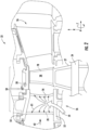
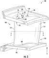
FIG. 3 illustrates a perspective view of a stator vane, in accordance with embodiments of the present disclosure; -
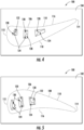
FIG. 4 illustrates a planar view of an outer platform of a stator vane from along the radial direction R, in accordance with embodiments of the present disclosure; -
FIG. 5 illustrates a planar view of an inner platform of a stator vane from along the radial direction R, in accordance with embodiments of the present disclosure; -
FIG. 6 illustrates a cross-sectional view of the stator vane shown inFIG. 3 from along the line 6-6, in accordance with embodiments of the present disclosure; -
FIG. 7 illustrates an enlarged view of the outline detail shown inFIG. 6 , in accordance with embodiments of the present disclosure; -
FIG. 8 illustrates a perspective view of an airfoil in which a plurality of passages are shown with dashed lines, in accordance with embodiments of the present disclosure; -
FIG. 9 schematically illustrates a cross-sectional view of the airfoil shown inFIG. 7 from along the line 9-9, in accordance with embodiments of the present disclosure; and -
FIG. 10 schematically illustrates a cross-sectional view of the airfoil shown inFIG. 7 from along the line 10-10, in accordance with embodiments of the present disclosure. - Reference now will be made in detail to embodiments of the present airfoils and stator vanes, one or more examples of which are illustrated in the drawings. Each example is provided by way of explanation, rather than limitation of, the technology. In fact, it will be apparent to those skilled in the art that modifications and variations can be made in the present technology without departing from the scope or spirit of the claimed technology. For instance, features illustrated or described as part of one embodiment can be used with another embodiment to yield a still further embodiment. Thus, it is intended that the present disclosure covers such modifications and variations as come within the scope of the appended claims and their equivalents.
- The word "exemplary" is used herein to mean "serving as an example, instance, or illustration." Any implementation described herein as "exemplary" is not necessarily to be construed as preferred or advantageous over other implementations. Additionally, unless specifically identified otherwise, all embodiments described herein should be considered exemplary.
- The detailed description uses numerical and letter designations to refer to features in the drawings. Like or similar designations in the drawings and description have been used to refer to like or similar parts of the invention. As used herein, the terms "first", "second", and "third" may be used interchangeably to distinguish one component from another and are not intended to signify location or importance of the individual components.
- The term "fluid" may be a gas or a liquid. The term "fluid communication" means that a fluid is capable of making the connection between the areas specified.
- As used herein, the terms "upstream" (or "forward") and "downstream" (or "aft") refer to the relative direction with respect to fluid flow in a fluid pathway. For example, "upstream" refers to the direction from which the fluid flows, and "downstream" refers to the direction to which the fluid flows. The term "radially" refers to the relative direction that is substantially perpendicular to an axial centerline of a particular component, the term "axially" refers to the relative direction that is substantially parallel and/or coaxially aligned to an axial centerline of a particular component, and the term "circumferentially" refers to the relative direction that extends around the axial centerline of a particular component.
- Terms of approximation, such as "about," "approximately," "generally," and "substantially," are not to be limited to the precise value specified. In at least some instances, the approximating language may correspond to the precision of an instrument for measuring the value, or the precision of the methods or machines for constructing or manufacturing the components and/or systems. In at least some instances, the approximating language may correspond to the precision of an instrument for measuring the value, or the precision of the methods or machines for constructing or manufacturing the components and/or systems. For example, the approximating language may refer to being within a 1, 2, 4, 5, 10, 15, or 20 percent margin in either individual values, range(s) of values and/or endpoints defining range(s) of values. When used in the context of an angle or direction, such terms include within ten degrees greater or less than the stated angle or direction. For example, "generally vertical" includes directions within ten degrees of vertical in any direction, e.g., clockwise or counter-clockwise.
- The terms "coupled," "fixed," "attached to," and the like refer to both direct coupling, fixing, or attaching, as well as indirect coupling, fixing, or attaching through one or more intermediate components or features, unless otherwise specified herein. As used herein, the terms "comprises," "comprising," "includes," "including," "has," "having" or any other variation thereof, are intended to cover a non-exclusive inclusion. For example, a process, method, article, or apparatus that comprises a list of features is not necessarily limited only to those features but may include other features that are not expressly listed or that are inherent to such process, method, article, or apparatus. Further, unless expressly stated to the contrary, "or" refers to an inclusive- or and not to an exclusive- or. For example, a condition A or B is satisfied by any one of the following: A is true (or present) and B is false (or not present); A is false (or not present) and B is true (or present); and both A and B are true (or present).
- Here and throughout the specification and claims, range limitations are combined and interchanged. Such ranges are identified and include all the sub-ranges contained therein unless context or language indicates otherwise. For example, all ranges disclosed herein are inclusive of the endpoints, and the endpoints are independently combinable with each other.
- Referring now to the drawings,
FIG. 1 illustrates a schematic diagram of one embodiment of a turbomachine, which in the illustrated embodiment is agas turbine engine 10. Although an industrial or land-based gas turbine is shown and described herein, the present disclosure is not limited to an industrial or land-based gas turbine unless otherwise specified in the claims. For example, the invention as described herein may be used in any type of turbomachine including but not limited to a steam turbine, an aircraft gas turbine, or a marine gas turbine. - As shown in
FIG. 1 , thegas turbine engine 10 generally includes acompressor section 12. Thecompressor section 12 includes acompressor 14. The compressor includes aninlet 16 that is disposed at an upstream end of thegas turbine engine 10. Thegas turbine engine 10 further includes acombustion section 18 having one ormore combustors 20 disposed downstream from thecompressor section 12. Thegas turbine engine 10 further includes aturbine section 22 that is downstream from thecombustion section 18. Ashaft 24 extends generally axially through thegas turbine engine 10. - The
compressor section 12 may generally include a plurality ofrotor disks 21 and a plurality ofrotor blades 23 extending radially outwardly from and connected to eachrotor disk 21. Eachrotor disk 21 in turn may be coupled to or form a portion of theshaft 24 that extends through thecompressor section 12. Therotor blades 23 of thecompressor section 12 may include turbomachine airfoils that define an airfoil shape (e.g., having a leading edge, a trailing edge, and side walls extending between the leading edge and the trailing edge). - The
turbine section 22 may generally include a plurality ofrotor disks 27 and a plurality ofrotor blades 28 extending radially outwardly from and being interconnected to eachrotor disk 27. Eachrotor disk 27 in turn may be coupled to or form a portion of theshaft 24 that extends through theturbine section 22. Theturbine section 22 further includes anouter casing 32 that circumferentially surrounds the portion of theshaft 24 and therotor blades 28. Theturbine section 22 may include stator vanes orstationary nozzles 26 extending radially inward from theouter casing 32. Therotor blades 28 andstator vanes 26 may be arranged in alternating stages along an axial centerline 30 ofgas turbine 10. Both therotor blades 28 and thestator vanes 26 may include turbomachine airfoils that define an airfoil shape (e.g., having a leading edge, a trailing edge, and side walls extending between the leading edge and the trailing edge). - In operation,
ambient air 36 or other working fluid is drawn into theinlet 16 of thecompressor 14 and is progressively compressed to provide acompressed air 38 to thecombustion section 18. Thecompressed air 38 flows into thecombustion section 18 and is mixed with fuel to form a combustible mixture. The combustible mixture is burned within acombustion chamber 40 of thecombustor 20, thereby generatingcombustion gases 42 that flow from thecombustion chamber 40 into theturbine section 22. Energy (kinetic and/or thermal) is transferred from thecombustion gases 42 to therotor blades 28, causing theshaft 24 to rotate and produce mechanical work. The spent combustion gases 42 ("exhaust gases") exit theturbine section 22 and flow through theexhaust diffuser 34 across a plurality of struts ormain airfoils 44 that are disposed within theexhaust diffuser 34. - The
gas turbine engine 10 may define a cylindrical coordinate system having an axial direction A extending along the axial centerline 30 coinciding with theshaft 24, a radial direction R perpendicular to the axial centerline 30, and a circumferential direction C extending around the axial centerline 30. -
FIG. 2 is a partial cross-sectional side view of theturbine section 22 of thegas turbine engine 10, in accordance with embodiments of the present disclosure. Theturbine section 22 may include one ormore stages 50 that each include a set ofrotor blades 28 coupled to arotor disk 27 that may be rotatably attached to theshaft 24. Each stage of the one ormore stages 50 may further include a set ofstator vanes 26. Thestator vane 26 described herein may be employed in a first stage, a second stage, a third stage, or others. As used herein, "first stage" refers to the stage immediately downstream of thecombustion section 18, such that the combustion gases engage the first stage stator vane immediately upon exit of the combustion section. In exemplary embodiments, thestator vane 26 described herein may be a first stage stator vane. - Each
stator vane 26 may include at least oneairfoil 56 that extends in the radial direction R between an inner platform or endwall 52 and an outer platform orendwall 54. The circumferentially adjacentouter platforms 54 of eachstator vane 26 may be coupled together to form an outer annular ring extending around an inner annular ring of the circumferentially adjacentinner platforms 52 of eachstator vane 26. The at least oneairfoil 56 may extend between the two annular rings formed by theplatforms turbine section 22 may also includeshroud segments 58, which may be disposed downstream of theouter platform 54 to directcombustion gases 42 flowing past thestator vanes 26 to therotor blades 28. - Structures or components disposed along the flow path of the
combustion gases 42 may be referred to as hot gas path components. In one example, the hot gas path component may be thestator vane 26 and/or therotor blade 28. In some embodiments, to cool the hot gas path components, cooling features, such as impingement sleeves, cooling channels, cooling holes, etc. may be disposed within the hot gas path components, as indicated by the dashedline 78. For example, cooling air as indicated by anarrow 79 may be routed from thecompressor section 12 or elsewhere and directed through the cooling features as indicated byarrows 81. As previously mentioned, to maintain high efficiency of thegas turbine engine 10, it is desirable to minimize the amount of coolingair 79 drawn from thecompressor section 12 to cool the hotgas path components - Referring now to
FIG. 3 , a perspective view of a stator vane 100 (26 inFIGS. 1 and2 ) is illustrated in accordance with embodiments of the present disclosure. In exemplary embodiments, thestator vane 100 may be a first stage stator vane, such that thestator vane 100 engages the combustion gases immediately after thecombustion gases 42 exit thecombustion section 18. As shown, thestator vane 100 includes aninner platform 102 spaced apart (e.g., radially spaced apart) from anouter platform 104. Theinner platform 102 and theouter platform 104 may define the radially inward/outward flow boundary for thecombustion gases 42. Anairfoil 106 may extend between theinner platform 102 and theouter platform 104. Particularly, theairfoil 106 may extend radially between a base 108 coupled to theinner platform 102 and atip 110 coupled to theouter platform 104. - The
airfoil 106 may further include aleading edge 112 spaced apart from a trailingedge 114. Additionally, theairfoil 106 may include apressure side wall 116 and asuction side wall 118 each extending between theleading edge 112 and the trailingedge 114. Theairfoil 106 may have a generally aerodynamic contour, such that thecombustion gases 42 engage theleading edge 112 and are guided along thepressure side wall 116 and thesuction side wall 118 to the trailingedge 114. - In exemplary embodiments, the
stator vane 100 may define acooling circuit 120 extending within theinner platform 102, theouter platform 104, and theairfoil 106 to provide convective cooling to thestator vane 100 during operation of thegas turbine 10. For example, thecooling circuit 120 may be in fluid communication with thecompressor section 12, such that thecooling circuit 120 receives a flow of compressed cooling air from thecompressor section 12. Particularly, thecooling circuit 120 may include a plurality ofpassages 122 extending span-wise (or radially) through theairfoil 106 and/or theinner platform 102 and theouter platform 104. - Each
passage 122 of the plurality ofpassages 122 may extend (e.g., generally radially) from aninlet 124 defined in one of the base 108 or thetip 110 to aclosed end 126 at the other of the base 108 or the tip 110 (as shown inFIGS. 8 through 10 ).FIG. 4 illustrates a planar view of theouter platform 104 of thestator vane 100 from along the radial direction R, andFIG. 5 illustrates a planar view of theinner platform 102 from along the radial direction R, in accordance with embodiments of the present disclosure. Particularly,FIGS. 4 and 5 illustrate theinlets 124 of the plurality ofpassages 122. - As shown in
FIG. 4 , the plurality ofpassages 122 may includeouter wall passages 128 havinginlets 124 defined through thetip 110 of theairfoil 106 and/or theouter platform 104 of thestator vane 100. Similarly, as shown inFIG. 5 , the plurality ofpassages 122 may includeinner wall passages 130 havinginlets 124 defined through thebase 108 of theairfoil 106 and/or theinner platform 102 of thestator vane 100. Additionally, as shown inFIG. 7 , the plurality ofpassages 122 may include aleading edge passage 132, anaft passage 134, and one or moreintermediary passages 136 disposed between theleading edge passage 132 and theaft passage 134. Theleading edge passage 132 may be aninner wall passage 130, such that theinlet 124 of the leading edge passage is defined through thebase 108 of theairfoil 106 and/or theinner platform 102 of thestator vane 100. By contrast, theaft passage 134 may be anouter wall passage 128, such that theinlet 124 of theaft passage 134 is defined through thetip 110 of theairfoil 106 and/or theouter platform 104 of thestator vane 100. - In exemplary embodiments, as shown by
FIGS. 4 and 5 collectively, theinlets 124 of the plurality ofpassages 122 may be defined in one of the base 108 or thetip 110 of the airfoil 106 (and/or the inner orouter platform leading edge 112 to the trailingedge 114 of theairfoil 106. In this way, eachpassage 122 of the plurality ofpassages 122 may have an inlet defined in one of the base 108 or thetip 110 of the airfoil, and eachpassage 122 may neighbor anotherpassage 122 having aninlet 124 defined in an opposite end of the airfoil 106 (e.g., the other of the base 108 or of thetip 110 compared to the neighboring passage(s) 122). - Particularly, the
airfoil 106 illustrated inFIGS. 4 and 5 may include sixpassages 122, in which three areouter wall passages 128 and three areinner wall passages 132 in an alternating pattern, as described above. However, it should be appreciated that theairfoil 106 may include any suitable number ofpassages 122 and should not be limited to any particular number of passages 122 (including outer/inner wall passages 128, 130) or any particular pattern ofpassages 122, unless specifically recited in the claims. -
FIG. 6 illustrates a cross-sectional view of thestator vane 100 from along the line 6-6 shown inFIG. 3 , andFIG. 7 illustrates an enlarged view of the outline detail shown inFIG. 6 , in accordance with embodiments of the present disclosure. As shown inFIGS. 6 and7 , eachpassage 122 of the plurality ofpassages 122 is defined at least partially by aprimary impingement wall 138 and asolid side wall 140. - Particularly, the
leading edge passage 132 may have a sharedside wall 141 that at least partially defines both theleading edge passage 132 and theneighboring passage 122 of the plurality of passages. The sharedside wall 141 may include one or more protrusions (such as a U-shaped protrusion) extending into thepassages 122 that the sharedside wall 141 partially defines. One or more of thepassages 122 of the plurality ofpassages 122 may be generally rectangular in cross-sectional shape. In various embodiments, one or more of thepassages 122 may be collectively defined by twosolid side walls 140, aprimary impingement wall 138, and asolid end wall 144. Thesolid end wall 144 may be spaced apart from theprimary impingement wall 138, and the twosolid side walls 140 may extend between thesolid end wall 144 and theprimary impingement wall 138. Thesolid end wall 144 and theprimary impingement wall 138 may be generally parallel to one another, and the twosolid side walls 140 may be generally parallel to one another. As used herein, "solid" may refer to a wall or other structure that does not include any apertures, passages, holes or other fluid permitting voids, such that the solid structure does not allow for fluid to pass therethrough. - In exemplary embodiments, the
primary impingement wall 138 may be spaced apart from one of thepressure side wall 116 or thesuction side wall 118 such that aprimary impingement gap 142 is defined therebetween. Particularly, theprimary impingement wall 138 may be spaced apart from an interior surface of thepressure side wall 116, such that theprimary impingement gap 142 is defined therebetween. In certain embodiments, theprimary impingement wall 138 may be generally contoured to correspond with thepressure side wall 116, such that theprimary impingement gap 142 may define a uniform distance along the entire radial span of the airfoil (e.g., from the base 108 to the tip 110) and along a majority of thepressure side 116 of the airfoil. One end of the sharedside wall 141 may extend beyond theprimary impingement wall 138 to the interior surface of thepressure side wall 116, and similarly theaft side wall 140 may extend beyond theprimary impingement wall 138 to the interior surface of thepressure side wall 116, such that the sharedside wall 141 and theaftmost side wall 140 bound theprimary impingement gap 142. - In many embodiments, the
primary impingement wall 138 may define a plurality ofimpingement apertures 146 that direct air in discrete jets across the impingement gap to impinge upon an interior surface of the airfoil. For example, the plurality ofimpingement apertures 146 may be sized and oriented to direct the air in discrete jets to impinge upon the interior surface of thepressure side wall 116. The discrete jets of fluid may have a sufficient velocity and pressure to travel across theprimary impingement gap 142 and impinge (or strike) the interior surface of the pressure side wall 116 (as opposed to fluid used for film cooling, which would be at a lower pressure and different orientation). The discrete jets of fluid impinge (or strike) the interior surface and create a thin boundary layer of fluid over the interior surface, which allows for optimal heat transfer between the pressure side wall 116 (or the suction side wall 118) and the fluid. - For example, the plurality of
impingement apertures 146 may extend generally perpendicularly through theprimary impingement wall 138, such that the plurality ofimpingement apertures 146 may orient pre-impingement fluid perpendicularly to the surface upon which it strikes, e.g., the interior surface of thepressure side wall 116. Once the fluid has impinged upon the interior surface, it may be referred to as "post-impingement fluid" and/or "spent cooling fluid" because the fluid has undergone an energy transfer and therefore has different characteristics. For example, the spent cooling fluid may have a higher temperature and lower pressure than the pre-impingement fluid because the spent cooling fluid has removed heat from thepressure side wall 116 during the impingement process. - As shown in
FIG. 7 , along theleading edge 112 of theairfoil 106, one end of the sharedside wall 141 may extend beyond theprimary impingement wall 138 to the interior surface of thepressure side wall 116 and the other end of the sharedside wall 141 may extend beyond theprimary impingement wall 138, such that the sharedside wall 141 defines opposite boundaries of a leadingedge impingement gap 143 between the interior surface of theleading edge 112 and theprimary impingement wall 138. - In an exemplary embodiment, as shown in
FIGS. 6 and7 , theairfoil 106 may further include a suction sidesecondary impingement wall 148 and a pressure sidesecondary impingement wall 150 that partially define a collection chamber orplenum 152. Particularly, thecollection chamber 152 may be collectively defined by the sharedside wall 141, thesolid end walls 144, the suction sidesecondary impingement wall 148, the pressure sidesecondary impingement wall 150, and one or moresolid side walls 140. Thecollection chamber 152 may collect the post-impingement fluid that has exited theprimary impingement wall 138 and impinged upon the interior surface of thepressure side wall 116. - In particular embodiments, the
solid side walls 140 of neighboringpassages 122 of the plurality ofpassages 122 collectively define acollection passage 154 that extends between theprimary impingement gap 142 and thecollection chamber 152. That is, two neighboringsolid side walls 140, which each partially define separate (but neighboring)passages 122, may collectively define thecollection passage 154 that extends between and fluidly couples theprimary impingement gap 142 to thecollection chamber 152. For example, thesolid side wall 140 of a first passage of the plurality ofpassages 122 and thesolid side wall 140 of an adjacent second passage of the plurality ofpassages 122 may collectively define thecollection passage 154 extending between theprimary impingement gap 142 and thecollection passage 152. In this way, air may enter theairfoil 106 via theinlets 124 of the plurality ofpassages 122 and exit the plurality ofpassages 122 into theprimary impingement gap 142 via the plurality ofimpingement apertures 146. Subsequently, the post-impingement air may travel through thecollection passage 154 into thecollection chamber 152. From thecollection chamber 152, the air may then travel through the suction sidesecondary impingement wall 148 and the pressure sidesecondary impingement wall 150. - In many embodiments, the suction side
secondary impingement wall 148 may extend from thesolid side wall 140 of aleading edge passage 132 of the plurality of passages toward or to the trailingedge 114. Particularly, the suction sidesecondary impingement wall 148 may extend from the sharedside wall 141 to a trailingedge portion 156. Thepressure side wall 116, thesuction side wall 118, the suction sidesecondary impingement wall 148, and the pressure sidesecondary impingement wall 150 may converge together at the trailingedge portion 156 of theairfoil 106. Additionally, the trailingedge portion 156 may define the trailingedge 114 of theairfoil 106. - In exemplary embodiments, the suction side
secondary impingement wall 148 may be spaced apart from thesuction side wall 118 such that asecondary impingement gap 158 is defined therebetween. Additionally, a plurality ofimpingement apertures 160 may be defined in the suction sidesecondary impingement wall 148 that direct air from thecollection chamber 152 in discrete jets across thesecondary impingement gap 158 to impinge upon an interior surface of thesuction side wall 118. For example, the plurality ofimpingement apertures 160 may extend generally perpendicularly through the suction sidesecondary impingement wall 148, such that the plurality ofimpingement apertures 160 may orient fluid perpendicularly to the surface upon which it strikes, e.g., the interior surface of thesuction side wall 118. In many embodiments, the suction sidesecondary impingement wall 148 may be contoured to correspond with thesuction side wall 118, such that thesecondary impingement gap 158 may define a uniform distance along the entire radial span of the airfoil (e.g., from the base 108 to the tip 110). - Similarly, in various embodiments, the pressure side
secondary impingement wall 150 may extend from thesolid side wall 140 of anaft passage 134 of the plurality ofpassages 122 toward or to the trailingedge 114. Particularly, the pressure sidesecondary impingement wall 150 may extend fromsolid side wall 140 of theaft passage 134 to the trailingedge portion 156. In exemplary embodiments, the pressure sidesecondary impingement wall 150 may be spaced apart from thepressure side wall 116 such that asecondary impingement gap 162 is defined therebetween. Additionally, a plurality ofimpingement apertures 164 may be defined in the pressure sidesecondary impingement wall 150 that direct air from thecollection chamber 152 in discrete jets across thesecondary impingement gap 162 to impinge upon an interior surface of thepressure side wall 116 aft of thepassages 122. For example, the plurality ofimpingement apertures 164 may extend generally perpendicularly through the pressure sidesecondary impingement wall 150, such that the plurality ofimpingement apertures 164 may orient fluid perpendicularly to the surface upon which it strikes, e.g., the interior surface of thepressure side wall 116. In many embodiments, the pressure sidesecondary impingement wall 150 may be contoured to correspond with the aft portion of thepressure side wall 116, such that thesecondary impingement gap 162 may define a uniform distance along the entire radial span of the airfoil (e.g., from the base 108 to the tip 110). - In many embodiments, the trailing
edge portion 156 may define a trailingedge cooling circuit 166 fluidly coupled to the secondary impingement gap 158 (e.g., the suction side secondary impingement gap) and the secondary impingement gap 162 (e.g., the pressure side secondary impingement gap). As shown, the trailingedge cooling circuit 166 may extend from thesecondary impingement gap 158 and thesecondary impingement gap 162 to anoutlet 168 at the trailingedge 114 of theairfoil 106. - In exemplary embodiments, as shown in
FIG. 7 , theairfoil 106 may further include one or more film cooling holes 176 defined through thepressure side wall 116 and/or thesuction side wall 118. Each of the film cooling holes 176 may be in fluid communication with one of theprimary impingement gap 142, the leadingedge impingement gap 143, or either of thesecondary impingement gaps pressure side wall 116, theleading edge 112, and/or thesuction side wall 118. The film cooling holes 176 may extend at an angle relative to the surfaces of the wall through which thefilm cooling hole 176 is defined. For example, afilm cooling hole 176 defined through thepressure side wall 116 will extend at an angle (i.e., not perpendicularly) to the interior surface and/or the exterior surface of thepressure side wall 116. -
FIG. 8 illustrates a perspective view of theairfoil 106, in which the plurality ofpassages 122 are shown with dashed lines. As shown, theinlets 124 of the plurality ofpassages 122 may be defined in one of the base 108 or thetip 110 of theairfoil 106 in an alternating pattern with respect to a direction extending from theleading edge 112 to the trailingedge 114 of theairfoil 106. In this way, eachpassage 122 of the plurality ofpassages 122 may have an inlet defined in one of the base 108 or thetip 110 of the airfoil, and eachneighboring passage 122 may have aninlet 124 defined in an opposite end of the airfoil 106 (e.g., the other of thebase 108 of thetip 110 than the neighboring passage(s) 122). -
FIG. 9 schematically illustrates a cross-sectional view of theairfoil 106 from along the line 9-9 shown inFIG. 7 , andFIG. 10 schematically illustrates a cross-sectional view of theairfoil 106 from along the line 10-10 shown inFIG. 7 , in accordance with embodiments of the present disclosure. Particularly,FIG. 9 may illustrate afirst passage 172 of the plurality ofpassages 122, andFIG. 10 may illustrate asecond passage 174 of the plurality of passages. Thefirst passage 172 and thesecond passage 174 may neighbor one another within the airfoil 106 (FIG. 7 ). Each passage 122 (including the first andsecond passages 172, 174) of the plurality ofpassages 122 may extend (e.g., generally radially) from aninlet 124 defined in one of the base 108 or thetip 110 to aclosed end 126 at or proximate to the other of the base 108 or thetip 110. Additionally, theinlets 124 of the plurality ofpassages 122 may be defined in one of the base 108 or thetip 110 of theairfoil 106 in an alternating pattern with respect to a direction extending from theleading edge 112 to the trailingedge 114 of theairfoil 106. In this way, eachpassage 122 having aninlet 124 defined at thetip 110 may neighbor one ormore passages 122 having an inlet defined at thebase 108. For example, as shown inFIGS. 9 and 10 , thefirst passage 172 may extend from aninlet 124 at thetip 110 to aclosed end 126 at or proximate to thebase 108. By contrast, the second passage 174 (which neighbors the first passage 172) may extend from aninlet 124 at the base 108 to aclosed end 126 at or proximate to thetip 110. - Additionally, as shown collectively in
FIGS. 7 through 10 , eachpassage 122 of the plurality ofpassages 122 may converge in cross-sectional area as thepassage 122 extends from theinlet 124 to theclosed end 126. For example, in some embodiments, eachpassage 122 may continually converge in cross-sectional area as thepassage 122 extends from theinlet 124 to theclosed end 126. This advantageously ensures that the air is exiting the plurality ofpassages 122 via theimpingement apertures 146 with sufficient velocity and pressure to traverse the primary impingement gap 142 (at any spanwise or radial location of the airfoil 106). Particularly, thesolid end wall 144 may converge towards theprimary impingement wall 138 from theinlet 124 of thepassage 122 to theclosed end 126. - In many embodiments, the
airfoil 106 described herein may be integrally formed as a single component. That is, each of the subcomponents, e.g., theprimary impingement wall 138, thesolid side walls 140, thesolid end walls 144, and/or other subcomponents, may be manufactured together as a single body. In exemplary embodiments, this may be done by utilizing an additive manufacturing system and method, such as direct metal laser sintering (DMLS), direct metal laser melting (DMLM), or other suitable additive manufacturing techniques. In this regard, by utilizing additive manufacturing methods, theairfoil 106 may be integrally formed as a single piece of continuous metal and may thus include fewer sub-components and/or joints compared to prior designs. The integral formation of theairfoil 106 through additive manufacturing may advantageously improve the overall assembly process. For example, the integral formation reduces the number of separate parts that must be assembled, thus reducing associated time and overall assembly costs. Additionally, existing issues with, for example, leakage, joint quality between separate parts, and overall performance may advantageously be reduced. Further, the integral formation of theairfoil 106 may favorably reduce the weight of theairfoil 106 as compared to other manufacturing methods. - In other embodiments, other manufacturing techniques, such as casting or other suitable techniques, may be used.
- This written description uses examples to disclose the invention, including the best mode, and also to enable any person skilled in the art to practice the invention, including making and using any devices or systems and performing any incorporated methods. The patentable scope of the invention is defined by the claims, and may include other examples that occur to those skilled in the art. Such other examples are intended to be within the scope of the claims if they include structural elements that do not differ from the literal language of the claims, or if they include equivalent structural elements with insubstantial differences from the literal language of the claims.
- Further aspects of the invention are provided by the subject matter of the following clauses:
- According to a first aspect, an airfoil comprises: a leading edge, a trailing edge, a base and a tip; a pressure side wall and a suction side wall extending between the leading edge, the trailing edge, the base, and the tip; and a plurality of passages defined within the airfoil and extending from an inlet at one of the base or the tip, wherein each passage of the plurality of passages is defined at least partially by a primary impingement wall and a solid side wall, the primary impingement wall spaced apart from one of the pressure side wall or the suction side wall such that a primary impingement gap is defined therebetween, the primary impingement wall defining a plurality of impingement apertures that direct air in discrete jets across the impingement gap to impinge upon an interior surface of the airfoil.
- The airfoil as in any of the preceding clauses, wherein each passage of the plurality of passages extends from the inlet at one of the base or the tip to a closed end at the other of the base or the tip.
- The airfoil as in any of the preceding clauses, wherein each passage of the plurality of passages converges in cross-sectional area as the passage extends between the inlet and the closed end.
- The airfoil as in any of the preceding clauses, wherein the inlets of the plurality of passages are defined in an alternating pattern in one of the base or the tip of the airfoil with respect to a direction extending from the leading edge to the trailing edge of the airfoil.
- The airfoil as in any of the preceding clauses, wherein the airfoil further includes a suction side secondary impingement wall and a pressure side secondary impingement wall that partially define a collection chamber.
- The airfoil as in any of the preceding clauses, wherein the solid side wall of a first passage of the plurality of passages and the solid side wall of an adjacent second passage of the plurality of passages collectively define a collection passage extending between the primary impingement gap and the collection chamber.
- The airfoil as in any of the preceding clauses, wherein the suction side secondary impingement wall extends from the solid side wall of a leading edge passage of the plurality of passages toward the trailing edge, wherein the suction side secondary impingement wall is spaced apart from the suction side wall such that a secondary impingement gap is defined therebetween, and wherein a plurality of impingement apertures are defined in the suction side secondary impingement wall to direct air from the collection chamber in discrete jets across the secondary impingement gap to impinge upon an interior surface of the suction side wall.
- The airfoil as in any of the preceding clauses, wherein the pressure side secondary impingement wall extends from the solid side wall of an aft passage of the plurality of passages toward the trailing edge, wherein the pressure side secondary impingement wall is spaced apart from the pressure side wall such that a secondary impingement gap is defined therebetween, and wherein a plurality of impingement apertures are defined in the pressure side secondary impingement wall to direct air from the collection chamber in discrete jets across the secondary impingement gap to impinge upon an interior surface of the pressure side wall.
- The airfoil as in any of the preceding clauses, wherein the primary impingement wall is contoured to correspond with the pressure side wall.
- The airfoil as in any of the preceding clauses, wherein the airfoil is integrally formed.
- A stator vane comprising: an inner platform; an outer platform; and an airfoil extending between a base coupled to the inner platform and a tip coupled to the outer platform, the airfoil comprising: a leading edge and a trailing edge; a pressure side wall and a suction side wall extending between the leading edge, the trailing edge, the base, and the tip; and a plurality of passages defined within the airfoil and extending from an inlet at one of the base or the tip, wherein each passage of the plurality of passages is defined at least partially by a primary impingement wall and a solid side wall, the primary impingement wall spaced apart from one of the pressure side wall or the suction side wall such that a primary impingement gap is defined therebetween, the primary impingement wall defining a plurality of impingement apertures that direct air in discrete jets across the impingement gap to impinge upon an interior surface of the airfoil.
- The stator vane as in any of the preceding clauses, wherein each passage of the plurality of passages extends from the inlet at one of the base or the tip to a closed end at the other of the base or the tip.
- The stator vane as in any of the preceding clauses, wherein each passage of the plurality of passages converges in cross-sectional area as the passage extends from the inlet to the closed end.
- The stator vane as in any of the preceding clauses, wherein the inlets of the plurality of passages are defined in an alternating pattern in one of the base or the tip of the airfoil with respect to a direction extending from the leading edge to the trailing edge of the airfoil.
- The stator vane as in any of the preceding clauses, wherein the airfoil further includes a suction side secondary impingement wall and a pressure side secondary impingement wall that partially define the collection chamber.
- The stator vane as in any of the preceding clauses, wherein the side wall of a first passage of the plurality of passages and the solid side wall of a second passage of the plurality of passages collectively define a collection passage extending between the primary impingement gap and the collection passage.
- The stator vane as in any of the preceding clauses, wherein the suction side secondary impingement wall extends from the solid side wall of a leading edge passage of the plurality of passages toward the trailing edge, wherein the suction side secondary impingement wall is spaced apart from the suction side wall such that a secondary impingement gap is defined therebetween, and wherein a plurality of impingement apertures are defined in the suction side secondary impingement wall to direct air from the collection chamber in discrete jets across the secondary impingement gap to impinge upon an interior surface of the suction side wall.
- The stator vane as in any of the preceding clauses, wherein the pressure side secondary impingement wall extends from the solid side wall of an aft passage of the plurality of passages toward the trailing edge, wherein the pressure side secondary impingement wall is spaced apart from the pressure side wall such that a secondary impingement gap is defined therebetween, and wherein a plurality of impingement apertures are defined in the pressure side secondary impingement wall to direct air from the collection chamber in discrete jets across the secondary impingement gap to impinge upon an interior surface of the pressure side wall.
- The stator vane as in any of the preceding clauses, wherein the primary impingement wall is contoured to correspond with the pressure side wall.
- The stator vane as in any of the preceding clauses, wherein the airfoil is integrally formed.
Claims (14)
- An airfoil (56, 106) comprising:a leading edge (112), a trailing edge (114), a base (108), and a tip (110);a pressure side wall (116) and a suction side wall (118) extending between the leading edge (112), the trailing edge (114), the base (108), and the tip (110); anda plurality of passages (122) defined within the airfoil (56, 106) and extending from an inlet (124) at one of the base (108) or the tip (110), wherein each passage (122) of the plurality of passages (122) is defined at least partially by a primary impingement wall (138) and a solid side wall (140), the primary impingement wall (138) spaced apart from one of the pressure side wall (116) or the suction side wall (118) such that a primary impingement gap (142) is defined therebetween, the primary impingement wall (138) defining a plurality of impingement apertures (146) that direct air in discrete jets across the primary impingement gap (142) to impinge upon an interior surface of the airfoil (56, 106).
- The airfoil (56, 106) as in claim 1, wherein each passage (122) of the plurality of passages (122) extends from the inlet (124) at one of the base (108) or the tip (110) to a closed end (126) at the other of the base (108) or the tip (110).
- The airfoil (56, 106) as in claim 2, wherein each passage (122) of the plurality of passages (122) converges in cross-sectional area as the passage (122) extends between the inlet (124) and the closed end (126).
- The airfoil (56, 106) as in claim 1, wherein the inlets (124) of the plurality of passages (122) are defined in an alternating pattern in one of the base (108) or the tip (110) of the airfoil (56, 106) with respect to a direction extending from the leading edge (112) to the trailing edge (114) of the airfoil (56, 106).
- The airfoil (56, 106) as in claim 1, wherein the airfoil (56, 106) further includes a suction side secondary impingement wall (148) and a pressure side secondary impingement wall (150) that partially define a collection chamber (152).
- The airfoil (56, 106) as in claim 5, wherein the solid side wall (140) of a first passage (122) of the plurality of passages (122) and the solid side wall (140) of an adjacent second passage (122) of the plurality of passages (122) collectively define a collection passage (154) extending between the primary impingement gap (142) and the collection chamber (152).
- The airfoil (56, 106) as in claim 5, wherein the suction side secondary impingement wall (148) extends from the solid side wall (140) of a leading edge passage (132) of the plurality of passages (122) toward the trailing edge (114), wherein the suction side secondary impingement wall (148) is spaced apart from the suction side wall (118) such that a secondary impingement gap (158) is defined therebetween, and wherein a plurality of impingement apertures (160) is defined in the suction side secondary impingement wall (148) to direct air from the collection chamber (152) in discrete jets across the secondary impingement gap (158) to impinge upon an interior surface of the suction side wall (118).
- The airfoil (56, 106) as in claim 5, wherein the pressure side secondary impingement wall (150) extends from the solid side wall (140) of an aft passage (134) of the plurality of passages (122) toward the trailing edge (114), wherein the pressure side secondary impingement wall (150) is spaced apart from the pressure side wall (116) such that a secondary impingement gap (162) is defined therebetween, and wherein a plurality of impingement apertures (164) is defined in the pressure side secondary impingement wall (150) to direct air from the collection chamber (152) in discrete jets across the secondary impingement gap (162) to impinge upon an interior surface of the pressure side wall (116).
- The airfoil (56, 106) as in claim 8, wherein a trailing edge cooling circuit 166 is disposed within a trailing edge portion 156 of the airfoil (56, 106), the trailing edge cooling circuit (166) being fluidly coupled to the secondary impingement gap (162) and extending from the secondary impingement gap (162) to an outlet (168) at the trailing edge (114) of the airfoil (56, 106).
- The airfoil (56,106) as in claim 8, wherein one or more film cooling holes (176) are defined through the pressure side wall (116) or the suction side wall (118), the one or more film cooling holes (176) being in fluid communication with one of the primary impingement gap (142) and the secondary impingement gap (162).
- The airfoil (56, 106) as in claim 1, wherein the primary impingement wall (138) is contoured to correspond with the pressure side wall (116).
- The airfoil (56, 106) as in claim 1, wherein the airfoil (56, 106) is integrally formed.
- A stator vane (26, 100) comprising:an inner platform (52, 102);an outer platform (54, 104); andan airfoil (56, 106) extending between a base (108) coupled to the inner platform (52, 102) and a tip (110) coupled to the outer platform (54, 104), the airfoil (56, 106) being defined according to any of claims 1 to 12.
- The stator vane (26, 100) as in claim 13, wherein the stator vane (26, 100) is configured for installation in a first stage of a turbine section (22) of a gas turbine engine (10).
Applications Claiming Priority (1)
| Application Number | Priority Date | Filing Date | Title |
|---|---|---|---|
| US17/877,085 US11767766B1 (en) | 2022-07-29 | 2022-07-29 | Turbomachine airfoil having impingement cooling passages |
Publications (2)
| Publication Number | Publication Date |
|---|---|
| EP4311913A1 true EP4311913A1 (en) | 2024-01-31 |
| EP4311913B1 EP4311913B1 (en) | 2026-05-13 |
Family
ID=87047926
Family Applications (1)
| Application Number | Title | Priority Date | Filing Date |
|---|---|---|---|
| EP23181374.2A Active EP4311913B1 (en) | 2022-07-29 | 2023-06-26 | Turbomachine airfoil having impingement cooling passages |
Country Status (5)
| Country | Link |
|---|---|
| US (1) | US11767766B1 (en) |
| EP (1) | EP4311913B1 (en) |
| JP (1) | JP2024018998A (en) |
| KR (1) | KR20240016880A (en) |
| CN (1) | CN117514367A (en) |
Families Citing this family (5)
| Publication number | Priority date | Publication date | Assignee | Title |
|---|---|---|---|---|
| US12203655B1 (en) | 2023-12-29 | 2025-01-21 | Ge Infrastructure Technology Llc | Additively manufactured combustor with adaptive cooling passage |
| US12092061B1 (en) | 2023-12-29 | 2024-09-17 | Ge Infrastructure Technology Llc | Axial fuel stage immersed injectors with internal cooling |
| US12601483B2 (en) | 2023-12-29 | 2026-04-14 | Ge Infrastructure Technology Llc | Additively manufactured combustion liner and axial fuel stage injector |
| US12281794B1 (en) | 2023-12-29 | 2025-04-22 | Ge Infrastructure Technology Llc | Combustor body and axial fuel stage immersed injectors additively manufactured with different materials |
| US12449128B1 (en) | 2024-11-27 | 2025-10-21 | Ge Vernova Infrastructure Technology Llc | Boss for a fuel injection assembly having cooling circuit and combustor provided therewith |
Citations (4)
| Publication number | Priority date | Publication date | Assignee | Title |
|---|---|---|---|---|
| US4252501A (en) * | 1973-11-15 | 1981-02-24 | Rolls-Royce Limited | Hollow cooled vane for a gas turbine engine |
| US20110103971A1 (en) * | 2008-11-07 | 2011-05-05 | Mitsubishi Heavy Industries, Ltd. | Turbine blade |
| US20200277860A1 (en) * | 2017-09-25 | 2020-09-03 | Siemens Aktiengesellschaft | Blade for a turbine blade |
| US11199097B2 (en) * | 2016-08-30 | 2021-12-14 | Rolls-Royce Corporation | Air-film cooled component for a gas turbine engine |
Family Cites Families (304)
| Publication number | Priority date | Publication date | Assignee | Title |
|---|---|---|---|---|
| US2595999A (en) | 1943-11-23 | 1952-05-06 | Westinghouse Electric Corp | Power plant combustion apparatus having apertured combustion chamber walls |
| US2625792A (en) | 1947-09-10 | 1953-01-20 | Rolls Royce | Flame tube having telescoping walls with fluted ends to admit air |
| US3433015A (en) | 1965-06-23 | 1969-03-18 | Nasa | Gas turbine combustion apparatus |
| US3584972A (en) | 1966-02-09 | 1971-06-15 | Gen Motors Corp | Laminated porous metal |
| US3657883A (en) | 1970-07-17 | 1972-04-25 | Westinghouse Electric Corp | Combustion chamber clustering structure |
| US3657882A (en) | 1970-11-13 | 1972-04-25 | Westinghouse Electric Corp | Combustion apparatus |
| US3750398A (en) | 1971-05-17 | 1973-08-07 | Westinghouse Electric Corp | Static seal structure |
| US4614082A (en) | 1972-12-19 | 1986-09-30 | General Electric Company | Combustion chamber construction |
| US4016718A (en) | 1975-07-21 | 1977-04-12 | United Technologies Corporation | Gas turbine engine having an improved transition duct support |
| US4112676A (en) | 1977-04-05 | 1978-09-12 | Westinghouse Electric Corp. | Hybrid combustor with staged injection of pre-mixed fuel |
| US4195474A (en) | 1977-10-17 | 1980-04-01 | General Electric Company | Liquid-cooled transition member to turbine inlet |
| US4158949A (en) | 1977-11-25 | 1979-06-26 | General Motors Corporation | Segmented annular combustor |
| US4253301A (en) | 1978-10-13 | 1981-03-03 | General Electric Company | Fuel injection staged sectoral combustor for burning low-BTU fuel gas |
| US4498288A (en) | 1978-10-13 | 1985-02-12 | General Electric Company | Fuel injection staged sectoral combustor for burning low-BTU fuel gas |
| JPS5554636A (en) | 1978-10-16 | 1980-04-22 | Hitachi Ltd | Combustor of gas turbine |
| US4373327A (en) | 1979-07-04 | 1983-02-15 | Rolls-Royce Limited | Gas turbine engine combustion chambers |
| US4422288A (en) | 1981-03-02 | 1983-12-27 | General Electric Company | Aft mounting system for combustion transition duct members |
| US4413470A (en) | 1981-03-05 | 1983-11-08 | Electric Power Research Institute, Inc. | Catalytic combustion system for a stationary combustion turbine having a transition duct mounted catalytic element |
| US4720970A (en) | 1982-11-05 | 1988-01-26 | The United States Of America As Represented By The Secretary Of The Air Force | Sector airflow variable geometry combustor |
| US4819438A (en) | 1982-12-23 | 1989-04-11 | United States Of America | Steam cooled rich-burn combustor liner |
| DE3317035A1 (en) | 1983-05-10 | 1984-11-15 | BBC Aktiengesellschaft Brown, Boveri & Cie., Baden, Aargau | MULTIPLE BURNER |
| US4719748A (en) | 1985-05-14 | 1988-01-19 | General Electric Company | Impingement cooled transition duct |
| US4798515A (en) * | 1986-05-19 | 1989-01-17 | The United States Of America As Represented By The Secretary Of The Air Force | Variable nozzle area turbine vane cooling |
| CA1309873C (en) | 1987-04-01 | 1992-11-10 | Graham P. Butt | Gas turbine combustor transition duct forced convection cooling |
| US4802823A (en) | 1988-05-09 | 1989-02-07 | Avco Corporation | Stress relief support structures and assemblies |
| US4843825A (en) | 1988-05-16 | 1989-07-04 | United Technologies Corporation | Combustor dome heat shield |
| US5297385A (en) | 1988-05-31 | 1994-03-29 | United Technologies Corporation | Combustor |
| US5075966A (en) | 1990-09-04 | 1991-12-31 | General Electric Company | Method for fabricating a hollow component for a rocket engine |
| US5181379A (en) | 1990-11-15 | 1993-01-26 | General Electric Company | Gas turbine engine multi-hole film cooled combustor liner and method of manufacture |
| US5274991A (en) | 1992-03-30 | 1994-01-04 | General Electric Company | Dry low NOx multi-nozzle combustion liner cap assembly |
| US5239818A (en) | 1992-03-30 | 1993-08-31 | General Electric Company | Dilution pole combustor and method |
| US5207556A (en) | 1992-04-27 | 1993-05-04 | General Electric Company | Airfoil having multi-passage baffle |
| US5237813A (en) | 1992-08-21 | 1993-08-24 | Allied-Signal Inc. | Annular combustor with outer transition liner cooling |
| FR2695460B1 (en) | 1992-09-09 | 1994-10-21 | Snecma | Combustion chamber of a turbomachine with several injectors. |
| US5323604A (en) | 1992-11-16 | 1994-06-28 | General Electric Company | Triple annular combustor for gas turbine engine |
| US5363654A (en) | 1993-05-10 | 1994-11-15 | General Electric Company | Recuperative impingement cooling of jet engine components |
| GB2278431A (en) | 1993-05-24 | 1994-11-30 | Rolls Royce Plc | A gas turbine engine combustion chamber |
| GB2284884B (en) | 1993-12-16 | 1997-12-10 | Rolls Royce Plc | A gas turbine engine combustion chamber |
| CA2141066A1 (en) | 1994-02-18 | 1995-08-19 | Urs Benz | Process for the cooling of an auto-ignition combustion chamber |
| JP2950720B2 (en) | 1994-02-24 | 1999-09-20 | 株式会社東芝 | Gas turbine combustion device and combustion control method therefor |
| US5415000A (en) | 1994-06-13 | 1995-05-16 | Westinghouse Electric Corporation | Low NOx combustor retro-fit system for gas turbines |
| US5480281A (en) | 1994-06-30 | 1996-01-02 | General Electric Co. | Impingement cooling apparatus for turbine shrouds having ducts of increasing cross-sectional area in the direction of post-impingement cooling flow |
| US5511375A (en) | 1994-09-12 | 1996-04-30 | General Electric Company | Dual fuel mixer for gas turbine combustor |
| DE69523545T2 (en) | 1994-12-20 | 2002-05-29 | General Electric Co., Schenectady | Reinforcement frame for gas turbine combustor tail |
| US5924288A (en) | 1994-12-22 | 1999-07-20 | General Electric Company | One-piece combustor cowl |
| US5836164A (en) | 1995-01-30 | 1998-11-17 | Hitachi, Ltd. | Gas turbine combustor |
| US5749229A (en) | 1995-10-13 | 1998-05-12 | General Electric Company | Thermal spreading combustor liner |
| DE19549143A1 (en) | 1995-12-29 | 1997-07-03 | Abb Research Ltd | Gas turbine ring combustor |
| US5826430A (en) | 1996-04-23 | 1998-10-27 | Westinghouse Electric Corporation | Fuel heating system used in conjunction with steam cooled combustors and transitions |
| US6047550A (en) | 1996-05-02 | 2000-04-11 | General Electric Co. | Premixing dry low NOx emissions combustor with lean direct injection of gas fuel |
| JP3276289B2 (en) | 1996-05-13 | 2002-04-22 | 三菱重工業株式会社 | Gas turbine combustor |
| US5822853A (en) | 1996-06-24 | 1998-10-20 | General Electric Company | Method for making cylindrical structures with cooling channels |
| US6951211B2 (en) | 1996-07-17 | 2005-10-04 | Bryant Clyde C | Cold air super-charged internal combustion engine, working cycle and method |
| JP3500020B2 (en) | 1996-11-29 | 2004-02-23 | 三菱重工業株式会社 | Steam cooled gas turbine system |
| DE19654472A1 (en) | 1996-12-27 | 1998-07-02 | Asea Brown Boveri | Process for cooling thermally highly loaded units of a gas turbine group |
| US5906093A (en) | 1997-02-21 | 1999-05-25 | Siemens Westinghouse Power Corporation | Gas turbine combustor transition |
| US6018950A (en) | 1997-06-13 | 2000-02-01 | Siemens Westinghouse Power Corporation | Combustion turbine modular cooling panel |
| DE29714742U1 (en) | 1997-08-18 | 1998-12-17 | Siemens AG, 80333 München | Heat shield component with cooling fluid return and heat shield arrangement for a hot gas-carrying component |
| US6456627B1 (en) | 1997-08-29 | 2002-09-24 | Telefonaktiebolaget Lm Ericsson (Publ) | Method for communicating information in a communication system that supports multiple modulation schemes |
| US6116013A (en) | 1998-01-02 | 2000-09-12 | Siemens Westinghouse Power Corporation | Bolted gas turbine combustor transition coupling |
| US6374593B1 (en) | 1998-03-20 | 2002-04-23 | Siemens Aktiengesellschaft | Burner and method for reducing combustion humming during operation |
| US6098397A (en) | 1998-06-08 | 2000-08-08 | Caterpillar Inc. | Combustor for a low-emissions gas turbine engine |
| US6082111A (en) | 1998-06-11 | 2000-07-04 | Siemens Westinghouse Power Corporation | Annular premix section for dry low-NOx combustors |
| US6357237B1 (en) | 1998-10-09 | 2002-03-19 | General Electric Company | Fuel injection assembly for gas turbine engine combustor |
| US6339923B1 (en) | 1998-10-09 | 2002-01-22 | General Electric Company | Fuel air mixer for a radial dome in a gas turbine engine combustor |
| FR2785664B1 (en) | 1998-11-05 | 2001-02-02 | Snecma | COMPOSITE MATERIAL HEAT EXCHANGER AND METHOD FOR THE PRODUCTION THEREOF |
| JP2001041005A (en) | 1999-08-02 | 2001-02-13 | Tohoku Electric Power Co Inc | Piping support for gas turbine steam cooled combustor |
| US6598383B1 (en) | 1999-12-08 | 2003-07-29 | General Electric Co. | Fuel system configuration and method for staging fuel for gas turbines utilizing both gaseous and liquid fuels |
| US6412268B1 (en) | 2000-04-06 | 2002-07-02 | General Electric Company | Cooling air recycling for gas turbine transition duct end frame and related method |
| JP2001289062A (en) | 2000-04-07 | 2001-10-19 | Mitsubishi Heavy Ind Ltd | Wall cooling structure of gas turbine combustor |
| EP1146289B1 (en) | 2000-04-13 | 2008-12-24 | Mitsubishi Heavy Industries, Ltd. | Cooling structure of combustor tail tube |
| IT1317978B1 (en) | 2000-06-16 | 2003-07-21 | Nuovo Pignone Spa | TRANSITION PIECE FOR COMBUSTION CHAMBERS OF NONANULAR GAS TURBINES. |
| US6298667B1 (en) | 2000-06-22 | 2001-10-09 | General Electric Company | Modular combustor dome |
| JP3846169B2 (en) | 2000-09-14 | 2006-11-15 | 株式会社日立製作所 | Gas turbine repair method |
| US6345494B1 (en) | 2000-09-20 | 2002-02-12 | Siemens Westinghouse Power Corporation | Side seal for combustor transitions |
| US6298656B1 (en) | 2000-09-29 | 2001-10-09 | Siemens Westinghouse Power Corporation | Compressed air steam generator for cooling combustion turbine transition section |
| US6536216B2 (en) | 2000-12-08 | 2003-03-25 | General Electric Company | Apparatus for injecting fuel into gas turbine engines |
| US6450762B1 (en) | 2001-01-31 | 2002-09-17 | General Electric Company | Integral aft seal for turbine applications |
| JP2002243154A (en) | 2001-02-16 | 2002-08-28 | Mitsubishi Heavy Ind Ltd | Gas turbine combustor transition piece outlet structure and gas turbine combustor |
| JP3962554B2 (en) | 2001-04-19 | 2007-08-22 | 三菱重工業株式会社 | Gas turbine combustor and gas turbine |
| JP4008212B2 (en) | 2001-06-29 | 2007-11-14 | 三菱重工業株式会社 | Hollow structure with flange |
| US6813889B2 (en) | 2001-08-29 | 2004-11-09 | Hitachi, Ltd. | Gas turbine combustor and operating method thereof |
| US6607355B2 (en) | 2001-10-09 | 2003-08-19 | United Technologies Corporation | Turbine airfoil with enhanced heat transfer |
| US6652220B2 (en) | 2001-11-15 | 2003-11-25 | General Electric Company | Methods and apparatus for cooling gas turbine nozzles |
| US6568187B1 (en) | 2001-12-10 | 2003-05-27 | Power Systems Mfg, Llc | Effusion cooled transition duct |
| US6699015B2 (en) | 2002-02-19 | 2004-03-02 | The Boeing Company | Blades having coolant channels lined with a shape memory alloy and an associated fabrication method |
| JP4134311B2 (en) | 2002-03-08 | 2008-08-20 | 独立行政法人 宇宙航空研究開発機構 | Gas turbine combustor |
| US6655147B2 (en) | 2002-04-10 | 2003-12-02 | General Electric Company | Annular one-piece corrugated liner for combustor of a gas turbine engine |
| US6921014B2 (en) | 2002-05-07 | 2005-07-26 | General Electric Company | Method for forming a channel on the surface of a metal substrate |
| ITMI20021526A1 (en) | 2002-07-11 | 2004-01-12 | Danieli Off Mecc | INJECTOR FOR METAL MATERIAL MELTING OVENS |
| US6619915B1 (en) | 2002-08-06 | 2003-09-16 | Power Systems Mfg, Llc | Thermally free aft frame for a transition duct |
| AU2003284210A1 (en) | 2002-10-15 | 2004-05-04 | Vast Power Systems, Inc. | Method and apparatus for mixing fluids |
| US6644032B1 (en) | 2002-10-22 | 2003-11-11 | Power Systems Mfg, Llc | Transition duct with enhanced profile optimization |
| US6931728B2 (en) | 2002-12-19 | 2005-08-23 | General Electric Company | Test model for a gas turbine combustor dome and method of fabricating |
| FR2850741B1 (en) | 2003-01-30 | 2005-09-23 | Snecma Propulsion Solide | PROCESS FOR MANUFACTURING AN ACTIVE COOLING PANEL OF THERMOSTRUCTURAL COMPOSITE MATERIAL |
| US20040177837A1 (en) | 2003-03-11 | 2004-09-16 | Bryant Clyde C. | Cold air super-charged internal combustion engine, working cycle & method |
| GB2402715B (en) | 2003-06-10 | 2006-06-14 | Rolls Royce Plc | Gas turbine aerofoil |
| US7104069B2 (en) | 2003-06-25 | 2006-09-12 | Power Systems Mfg., Llc | Apparatus and method for improving combustion stability |
| US20050056313A1 (en) | 2003-09-12 | 2005-03-17 | Hagen David L. | Method and apparatus for mixing fluids |
| US7270175B2 (en) | 2004-01-09 | 2007-09-18 | United Technologies Corporation | Extended impingement cooling device and method |
| US7185494B2 (en) | 2004-04-12 | 2007-03-06 | General Electric Company | Reduced center burner in multi-burner combustor and method for operating the combustor |
| US7010921B2 (en) | 2004-06-01 | 2006-03-14 | General Electric Company | Method and apparatus for cooling combustor liner and transition piece of a gas turbine |
| US7197877B2 (en) | 2004-08-04 | 2007-04-03 | Siemens Power Generation, Inc. | Support system for a pilot nozzle of a turbine engine |
| US7325402B2 (en) | 2004-08-04 | 2008-02-05 | Siemens Power Generation, Inc. | Pilot nozzle heat shield having connected tangs |
| US7219498B2 (en) | 2004-09-10 | 2007-05-22 | Honeywell International, Inc. | Waffled impingement effusion method |
| US7377036B2 (en) | 2004-10-05 | 2008-05-27 | General Electric Company | Methods for tuning fuel injection assemblies for a gas turbine fuel nozzle |
| US7310938B2 (en) | 2004-12-16 | 2007-12-25 | Siemens Power Generation, Inc. | Cooled gas turbine transition duct |
| US8015818B2 (en) | 2005-02-22 | 2011-09-13 | Siemens Energy, Inc. | Cooled transition duct for a gas turbine engine |
| US7437876B2 (en) | 2005-03-25 | 2008-10-21 | General Electric Company | Augmenter swirler pilot |
| WO2006108444A1 (en) | 2005-04-13 | 2006-10-19 | Freescale Semiconductor, Inc | Protection of an integrated circuit and method therefor |
| US7779636B2 (en) | 2005-05-04 | 2010-08-24 | Delavan Inc | Lean direct injection atomizer for gas turbine engines |
| US7334960B2 (en) | 2005-06-23 | 2008-02-26 | Siemens Power Generation, Inc. | Attachment device for removable components in hot gas paths in a turbine engine |
| US8720205B2 (en) | 2005-09-09 | 2014-05-13 | Richard H. Lugg | Advanced hypersonic magnetic jet/electric turbine engine (AHMJET) |
| WO2007033306A2 (en) | 2005-09-13 | 2007-03-22 | Rolls-Royce Corporation, Ltd. | Gas turbine engine combustion systems |
| JP2007113888A (en) | 2005-10-24 | 2007-05-10 | Kawasaki Heavy Ind Ltd | Gas turbine engine combustor structure |
| JP5137379B2 (en) | 2005-11-14 | 2013-02-06 | インターナショナル・ビジネス・マシーンズ・コーポレーション | Collision cooler |
| US8500628B2 (en) | 2006-02-28 | 2013-08-06 | Olympus Endo Technology America, Inc. | Rotate-to-advance catheterization system |
| US7762073B2 (en) | 2006-03-01 | 2010-07-27 | General Electric Company | Pilot mixer for mixer assembly of a gas turbine engine combustor having a primary fuel injector and a plurality of secondary fuel injection ports |
| US7690203B2 (en) | 2006-03-17 | 2010-04-06 | Siemens Energy, Inc. | Removable diffusion stage for gas turbine engine fuel nozzle assemblages |
| DE102006026969A1 (en) | 2006-06-09 | 2007-12-13 | Rolls-Royce Deutschland Ltd & Co Kg | Gas turbine combustor wall for a lean-burn gas turbine combustor |
| EP2126355A2 (en) | 2006-12-16 | 2009-12-02 | Christopher J. Papile | Methods and/or systems for removing carbon dioxide and/or generating power |
| US7886517B2 (en) | 2007-05-09 | 2011-02-15 | Siemens Energy, Inc. | Impingement jets coupled to cooling channels for transition cooling |
| GB0709838D0 (en) | 2007-05-23 | 2007-07-04 | Rolls Royce Plc | A hollow blade and a method of manufacturing a hollow blade |
| US7836703B2 (en) | 2007-06-20 | 2010-11-23 | General Electric Company | Reciprocal cooled turbine nozzle |
| US8011188B2 (en) | 2007-08-31 | 2011-09-06 | General Electric Company | Augmentor with trapped vortex cavity pilot |
| US7921654B1 (en) * | 2007-09-07 | 2011-04-12 | Florida Turbine Technologies, Inc. | Cooled turbine stator vane |
| US7665309B2 (en) | 2007-09-14 | 2010-02-23 | Siemens Energy, Inc. | Secondary fuel delivery system |
| US8387398B2 (en) | 2007-09-14 | 2013-03-05 | Siemens Energy, Inc. | Apparatus and method for controlling the secondary injection of fuel |
| JP4823186B2 (en) | 2007-09-25 | 2011-11-24 | 三菱重工業株式会社 | Gas turbine combustor |
| US8151570B2 (en) | 2007-12-06 | 2012-04-10 | Alstom Technology Ltd | Transition duct cooling feed tubes |
| US8104292B2 (en) | 2007-12-17 | 2012-01-31 | General Electric Company | Duplex turbine shroud |
| US20090223227A1 (en) | 2008-03-05 | 2009-09-10 | General Electric Company | Combustion cap with crown mixing holes |
| US8393867B2 (en) | 2008-03-31 | 2013-03-12 | United Technologies Corporation | Chambered airfoil cooling |
| US7757491B2 (en) | 2008-05-09 | 2010-07-20 | General Electric Company | Fuel nozzle for a gas turbine engine and method for fabricating the same |
| US8281595B2 (en) | 2008-05-28 | 2012-10-09 | General Electric Company | Fuse for flame holding abatement in premixer of combustion chamber of gas turbine and associated method |
| US8590313B2 (en) | 2008-07-30 | 2013-11-26 | Rolls-Royce Corporation | Precision counter-swirl combustor |
| US8087228B2 (en) | 2008-09-11 | 2012-01-03 | General Electric Company | Segmented combustor cap |
| US7874138B2 (en) | 2008-09-11 | 2011-01-25 | Siemens Energy, Inc. | Segmented annular combustor |
| US8375726B2 (en) | 2008-09-24 | 2013-02-19 | Siemens Energy, Inc. | Combustor assembly in a gas turbine engine |
| US8272218B2 (en) | 2008-09-24 | 2012-09-25 | Siemens Energy, Inc. | Spiral cooled fuel nozzle |
| US8230688B2 (en) | 2008-09-29 | 2012-07-31 | Siemens Energy, Inc. | Modular transvane assembly |
| CN105089714B (en) | 2008-10-08 | 2017-10-17 | 三菱重工业株式会社 | Gas turbine and its method of operation |
| US8209986B2 (en) | 2008-10-29 | 2012-07-03 | General Electric Company | Multi-tube thermal fuse for nozzle protection from a flame holding or flashback event |
| US8231329B2 (en) * | 2008-12-30 | 2012-07-31 | General Electric Company | Turbine blade cooling with a hollow airfoil configured to minimize a distance between a pin array section and the trailing edge of the air foil |
| US8549861B2 (en) | 2009-01-07 | 2013-10-08 | General Electric Company | Method and apparatus to enhance transition duct cooling in a gas turbine engine |
| US9140454B2 (en) | 2009-01-23 | 2015-09-22 | General Electric Company | Bundled multi-tube nozzle for a turbomachine |
| US20100192582A1 (en) | 2009-02-04 | 2010-08-05 | Robert Bland | Combustor nozzle |
| US8851402B2 (en) | 2009-02-12 | 2014-10-07 | General Electric Company | Fuel injection for gas turbine combustors |
| US20100205970A1 (en) | 2009-02-19 | 2010-08-19 | General Electric Company | Systems, Methods, and Apparatus Providing a Secondary Fuel Nozzle Assembly |
| US20100223931A1 (en) | 2009-03-04 | 2010-09-09 | General Electric Company | Pattern cooled combustor liner |
| US8307657B2 (en) | 2009-03-10 | 2012-11-13 | General Electric Company | Combustor liner cooling system |
| US20100272953A1 (en) | 2009-04-28 | 2010-10-28 | Honeywell International Inc. | Cooled hybrid structure for gas turbine engine and method for the fabrication thereof |
| JP5476462B2 (en) | 2009-05-07 | 2014-04-23 | ゼネラル・エレクトリック・カンパニイ | Multi premixer fuel nozzle |
| JP5107463B2 (en) * | 2009-05-11 | 2012-12-26 | 三菱重工業株式会社 | Turbine vane and gas turbine |
| US8904799B2 (en) | 2009-05-25 | 2014-12-09 | Majed Toqan | Tangential combustor with vaneless turbine for use on gas turbine engines |
| JP5439041B2 (en) | 2009-06-02 | 2014-03-12 | 三菱重工業株式会社 | Combustor component manufacturing method, combustor component, gas turbine combustor, and gas turbine |
| US8616002B2 (en) | 2009-07-23 | 2013-12-31 | General Electric Company | Gas turbine premixing systems |
| US8707705B2 (en) | 2009-09-03 | 2014-04-29 | General Electric Company | Impingement cooled transition piece aft frame |
| US8281594B2 (en) | 2009-09-08 | 2012-10-09 | Siemens Energy, Inc. | Fuel injector for use in a gas turbine engine |
| JP2011058775A (en) | 2009-09-14 | 2011-03-24 | Hitachi Ltd | Gas turbine combustor |
| JP5103454B2 (en) | 2009-09-30 | 2012-12-19 | 株式会社日立製作所 | Combustor |
| US8276385B2 (en) | 2009-10-08 | 2012-10-02 | General Electric Company | Staged multi-tube premixing injector |
| WO2011054760A1 (en) | 2009-11-07 | 2011-05-12 | Alstom Technology Ltd | A cooling scheme for an increased gas turbine efficiency |
| US9397361B2 (en) | 2009-12-02 | 2016-07-19 | Christopher J Papile | Generating power from hydrocarbon deposits while capturing carbon dioxide |
| JP5479058B2 (en) | 2009-12-07 | 2014-04-23 | 三菱重工業株式会社 | Communication structure between combustor and turbine section, and gas turbine |
| US8381532B2 (en) | 2010-01-27 | 2013-02-26 | General Electric Company | Bled diffuser fed secondary combustion system for gas turbines |
| RU2530685C2 (en) | 2010-03-25 | 2014-10-10 | Дженерал Электрик Компани | Impact action structures for cooling systems |
| US20110247340A1 (en) | 2010-04-13 | 2011-10-13 | Predrag Popovic | Apparatus and method for minimizing and/or eliminating dilution air leakage in a combustion liner assembly |
| US8276391B2 (en) | 2010-04-19 | 2012-10-02 | General Electric Company | Combustor liner cooling at transition duct interface and related method |
| US8752386B2 (en) | 2010-05-25 | 2014-06-17 | Siemens Energy, Inc. | Air/fuel supply system for use in a gas turbine engine |
| RU2531110C2 (en) | 2010-06-29 | 2014-10-20 | Дженерал Электрик Компани | Gas-turbine unit and unit with injector vanes (versions) |
| US8141334B2 (en) | 2010-08-02 | 2012-03-27 | General Electric Company | Apparatus and filtering systems relating to combustors in combustion turbine engines |
| US9334808B2 (en) | 2010-08-05 | 2016-05-10 | Mitsubishi Hitachi Power Systems, Ltd. | Combustor and the method of fuel supply and converting fuel nozzle for advanced humid air turbine |
| US8647053B2 (en) | 2010-08-09 | 2014-02-11 | Siemens Energy, Inc. | Cooling arrangement for a turbine component |
| US8499566B2 (en) | 2010-08-12 | 2013-08-06 | General Electric Company | Combustor liner cooling system |
| JP5653705B2 (en) | 2010-09-30 | 2015-01-14 | 三菱重工業株式会社 | Recovery air cooling gas turbine combustor cooling structure |
| EP2436977A1 (en) | 2010-09-30 | 2012-04-04 | Siemens Aktiengesellschaft | Burner for a gas turbine |
| US8464537B2 (en) | 2010-10-21 | 2013-06-18 | General Electric Company | Fuel nozzle for combustor |
| US20120114868A1 (en) | 2010-11-10 | 2012-05-10 | General Electric Company | Method of fabricating a component using a fugitive coating |
| US9097117B2 (en) | 2010-11-15 | 2015-08-04 | Siemens Energy, Inc | Turbine transition component formed from an air-cooled multi-layer outer panel for use in a gas turbine engine |
| US9133721B2 (en) | 2010-11-15 | 2015-09-15 | Siemens Energy, Inc. | Turbine transition component formed from a two section, air-cooled multi-layer outer panel for use in a gas turbine engine |
| US20120151928A1 (en) | 2010-12-17 | 2012-06-21 | Nayan Vinodbhai Patel | Cooling flowpath dirt deflector in fuel nozzle |
| US8726668B2 (en) | 2010-12-17 | 2014-05-20 | General Electric Company | Fuel atomization dual orifice fuel nozzle |
| US8387391B2 (en) | 2010-12-17 | 2013-03-05 | General Electric Company | Aerodynamically enhanced fuel nozzle |
| US8899049B2 (en) | 2011-01-07 | 2014-12-02 | General Electric Company | System and method for controlling combustor operating conditions based on flame detection |
| US8322143B2 (en) | 2011-01-18 | 2012-12-04 | General Electric Company | System and method for injecting fuel |
| US20120180487A1 (en) | 2011-01-19 | 2012-07-19 | General Electric Company | System for flow control in multi-tube fuel nozzle |
| US8720204B2 (en) | 2011-02-09 | 2014-05-13 | Siemens Energy, Inc. | Resonator system with enhanced combustor liner cooling |
| KR101471311B1 (en) | 2011-03-16 | 2014-12-09 | 미츠비시 쥬고교 가부시키가이샤 | Gas turbine combustor and gas turbine |
| US8667682B2 (en) | 2011-04-27 | 2014-03-11 | Siemens Energy, Inc. | Method of fabricating a nearwall nozzle impingement cooled component for an internal combustion engine |
| KR20130116948A (en) | 2011-05-24 | 2013-10-24 | 미츠비시 쥬고교 가부시키가이샤 | Hollow curved plate, method for manufacturing same, and burner for gas turbine |
| US8904797B2 (en) | 2011-07-29 | 2014-12-09 | General Electric Company | Sector nozzle mounting systems |
| EP2573325A1 (en) | 2011-09-23 | 2013-03-27 | Siemens Aktiengesellschaft | Impingement cooling of turbine blades or vanes |
| US8801428B2 (en) | 2011-10-04 | 2014-08-12 | General Electric Company | Combustor and method for supplying fuel to a combustor |
| US9243803B2 (en) | 2011-10-06 | 2016-01-26 | General Electric Company | System for cooling a multi-tube fuel nozzle |
| US9188335B2 (en) | 2011-10-26 | 2015-11-17 | General Electric Company | System and method for reducing combustion dynamics and NOx in a combustor |
| FR2982008B1 (en) | 2011-10-26 | 2013-12-13 | Snecma | ANNULAR ROOM OF COMBUSTION CHAMBER WITH IMPROVED COOLING AT THE PRIMARY HOLES AND DILUTION HOLES |
| US9033699B2 (en) | 2011-11-11 | 2015-05-19 | General Electric Company | Combustor |
| US9243506B2 (en) | 2012-01-03 | 2016-01-26 | General Electric Company | Methods and systems for cooling a transition nozzle |
| US9366440B2 (en) | 2012-01-04 | 2016-06-14 | General Electric Company | Fuel nozzles with mixing tubes surrounding a liquid fuel cartridge for injecting fuel in a gas turbine combustor |
| EP2613080A1 (en) | 2012-01-05 | 2013-07-10 | Siemens Aktiengesellschaft | Combustion chamber of an annular combustor for a gas turbine |
| US10161691B2 (en) | 2012-01-16 | 2018-12-25 | The Boeing Company | Multi-channel cooling plenum |
| EP2626519A1 (en) * | 2012-02-09 | 2013-08-14 | Siemens Aktiengesellschaft | Turbine assembly, corresponding impingement cooling tube and gas turbine engine |
| US8511086B1 (en) | 2012-03-01 | 2013-08-20 | General Electric Company | System and method for reducing combustion dynamics in a combustor |
| US9016039B2 (en) | 2012-04-05 | 2015-04-28 | General Electric Company | Combustor and method for supplying fuel to a combustor |
| EP2650612A1 (en) | 2012-04-10 | 2013-10-16 | Siemens Aktiengesellschaft | Burner |
| US9121286B2 (en) | 2012-04-24 | 2015-09-01 | United Technologies Corporation | Airfoil having tapered buttress |
| US9234438B2 (en) | 2012-05-04 | 2016-01-12 | Siemens Aktiengesellschaft | Turbine engine component wall having branched cooling passages |
| US9534781B2 (en) | 2012-05-10 | 2017-01-03 | General Electric Company | System and method having multi-tube fuel nozzle with differential flow |
| EP2666613A1 (en) | 2012-05-25 | 2013-11-27 | Technische Universität Darmstadt | Invention related to auxiliary structures for the production of components by means of generative or additive methods |
| US20130318986A1 (en) | 2012-06-05 | 2013-12-05 | General Electric Company | Impingement cooled combustor |
| RU2561956C2 (en) | 2012-07-09 | 2015-09-10 | Альстом Текнолоджи Лтд | Gas-turbine combustion system |
| US8904798B2 (en) | 2012-07-31 | 2014-12-09 | General Electric Company | Combustor |
| US8966909B2 (en) | 2012-08-21 | 2015-03-03 | General Electric Company | System for reducing combustion dynamics |
| US9212823B2 (en) | 2012-09-06 | 2015-12-15 | General Electric Company | Systems and methods for suppressing combustion driven pressure fluctuations with a premix combustor having multiple premix times |
| US9335050B2 (en) | 2012-09-26 | 2016-05-10 | United Technologies Corporation | Gas turbine engine combustor |
| US20140093379A1 (en) | 2012-10-03 | 2014-04-03 | Rolls-Royce Plc | Gas turbine engine component |
| US9297310B2 (en) | 2012-10-18 | 2016-03-29 | General Electric Company | Part load performance improvement using deformable bore plugs |
| WO2015057288A1 (en) | 2013-10-18 | 2015-04-23 | Florida Turbine Technologies, Inc. | Gas turbine engine with liquid metal cooling |
| EP2923150B1 (en) | 2012-11-21 | 2018-09-05 | General Electric Company | Anti-coking liquid fuel cartridge |
| US20140144152A1 (en) | 2012-11-26 | 2014-05-29 | General Electric Company | Premixer With Fuel Tubes Having Chevron Outlets |
| US9599343B2 (en) | 2012-11-28 | 2017-03-21 | General Electric Company | Fuel nozzle for use in a turbine engine and method of assembly |
| EP2762784B1 (en) | 2012-11-30 | 2016-02-03 | Alstom Technology Ltd | Damping device for a gas turbine combustor |
| EP2738469B1 (en) | 2012-11-30 | 2019-04-17 | Ansaldo Energia IP UK Limited | Combustor part of a gas turbine comprising a near wall cooling arrangement |
| US9353950B2 (en) | 2012-12-10 | 2016-05-31 | General Electric Company | System for reducing combustion dynamics and NOx in a combustor |
| US9366437B2 (en) | 2012-12-20 | 2016-06-14 | General Electric Company | System for reducing flame holding within a combustor |
| US9486963B2 (en) | 2012-12-28 | 2016-11-08 | United Technologies Corporation | Work piece having self-supporting gusset and method related thereto |
| US9309809B2 (en) | 2013-01-23 | 2016-04-12 | General Electric Company | Effusion plate using additive manufacturing methods |
| US9562692B2 (en) | 2013-02-06 | 2017-02-07 | Siemens Aktiengesellschaft | Nozzle with multi-tube fuel passageway for gas turbine engines |
| US9435539B2 (en) | 2013-02-06 | 2016-09-06 | General Electric Company | Variable volume combustor with pre-nozzle fuel injection system |
| US9015944B2 (en) | 2013-02-22 | 2015-04-28 | General Electric Company | Method of forming a microchannel cooled component |
| US20140260327A1 (en) | 2013-02-26 | 2014-09-18 | General Electric Company | Cooled article |
| EP2965010B1 (en) | 2013-03-05 | 2018-10-17 | Rolls-Royce Corporation | Dual-wall impingement, convection, effusion combustor tile |
| US9759425B2 (en) | 2013-03-12 | 2017-09-12 | General Electric Company | System and method having multi-tube fuel nozzle with multiple fuel injectors |
| US20140338340A1 (en) | 2013-03-12 | 2014-11-20 | General Electric Company | System and method for tube level air flow conditioning |
| US9551299B2 (en) | 2013-03-13 | 2017-01-24 | Rolls-Royce Corporation | Check valve for propulsive engine combustion chamber |
| US9528701B2 (en) | 2013-03-15 | 2016-12-27 | General Electric Company | System for tuning a combustor of a gas turbine |
| WO2014143209A1 (en) | 2013-03-15 | 2014-09-18 | Rolls-Royce Corporation | Gas turbine engine combustor liner |
| US9458767B2 (en) | 2013-03-18 | 2016-10-04 | General Electric Company | Fuel injection insert for a turbine nozzle segment |
| US9360217B2 (en) | 2013-03-18 | 2016-06-07 | General Electric Company | Flow sleeve for a combustion module of a gas turbine |
| GB201305432D0 (en) | 2013-03-26 | 2013-05-08 | Rolls Royce Plc | A gas turbine engine cooling arrangement |
| WO2014191495A1 (en) | 2013-05-31 | 2014-12-04 | Siemens Aktiengesellschaft | Annular combustion chamber for a gas turbine, with tangential injection for late lean injection |
| US9371997B2 (en) | 2013-07-01 | 2016-06-21 | General Electric Company | System for supporting a bundled tube fuel injector within a combustor |
| US9273868B2 (en) | 2013-08-06 | 2016-03-01 | General Electric Company | System for supporting bundled tube segments within a combustor |
| US20150041590A1 (en) | 2013-08-09 | 2015-02-12 | General Electric Company | Airfoil with a trailing edge supplement structure |
| US20150044059A1 (en) | 2013-08-09 | 2015-02-12 | General Electric Company | Airfoil for a turbine system |
| US20150059348A1 (en) | 2013-08-28 | 2015-03-05 | General Electric Company | System and method for controlling fuel distributions in a combustor in a gas turbine engine |
| US9416662B2 (en) | 2013-09-03 | 2016-08-16 | General Electric Company | Method and system for providing cooling for turbine components |
| US10539327B2 (en) | 2013-09-11 | 2020-01-21 | United Technologies Corporation | Combustor liner |
| US9476592B2 (en) | 2013-09-19 | 2016-10-25 | General Electric Company | System for injecting fuel in a gas turbine combustor |
| US9574498B2 (en) | 2013-09-25 | 2017-02-21 | General Electric Company | Internally cooled transition duct aft frame with serpentine cooling passage and conduit |
| US9458725B2 (en) | 2013-10-04 | 2016-10-04 | General Electric Company | Method and system for providing cooling for turbine components |
| EP2863018B1 (en) | 2013-10-17 | 2018-03-21 | Ansaldo Energia Switzerland AG | Combustor of a gas turbine with a transition piece having a cooling structure |
| US10539041B2 (en) | 2013-10-22 | 2020-01-21 | General Electric Company | Cooled article and method of forming a cooled article |
| US9518478B2 (en) | 2013-10-28 | 2016-12-13 | General Electric Company | Microchannel exhaust for cooling and/or purging gas turbine segment gaps |
| US9423135B2 (en) | 2013-11-21 | 2016-08-23 | General Electric Company | Combustor having mixing tube bundle with baffle arrangement for directing fuel |
| US9909432B2 (en) | 2013-11-26 | 2018-03-06 | General Electric Company | Gas turbine transition piece aft frame assemblies with cooling channels and methods for manufacturing the same |
| US9259807B2 (en) | 2013-12-13 | 2016-02-16 | General Electric Company | Method for repairing a bundled tube fuel injector |
| US20150167983A1 (en) | 2013-12-13 | 2015-06-18 | General Electric Company | Bundled tube fuel injector tube tip |
| US20150219336A1 (en) | 2014-02-03 | 2015-08-06 | General Electric Company | Systems and methods for reducing modal coupling of combustion dynamics |
| US9410702B2 (en) | 2014-02-10 | 2016-08-09 | Honeywell International Inc. | Gas turbine engine combustors with effusion and impingement cooling and methods for manufacturing the same using additive manufacturing techniques |
| JP6177187B2 (en) | 2014-04-30 | 2017-08-09 | 三菱日立パワーシステムズ株式会社 | Gas turbine combustor, gas turbine, control apparatus and control method |
| WO2015174880A1 (en) | 2014-05-12 | 2015-11-19 | General Electric Company | Pre-film liquid fuel cartridge |
| US10161635B2 (en) | 2014-06-13 | 2018-12-25 | Rolls-Royce Corporation | Combustor with spring-loaded crossover tubes |
| US9333578B2 (en) | 2014-06-30 | 2016-05-10 | General Electric Company | Fiber reinforced brazed components and methods |
| CN107027298B (en) | 2014-07-04 | 2020-06-30 | 诺沃皮尼奥内股份有限公司 | Manufacture of a turbine wheel by assembling a plurality of turbine components |
| US9650958B2 (en) | 2014-07-17 | 2017-05-16 | General Electric Company | Combustor cap with cooling passage |
| FR3024060B1 (en) | 2014-07-28 | 2021-01-29 | Michelin & Cie | ADDITIVE POWDER-BASED MANUFACTURING PROCESS OF A PIECE, IN PARTICULAR A LINING FLAP FOR A TIRE MOLD, AND AN ASSOCIATED REINFORCEMENT ELEMENT |
| US10480791B2 (en) | 2014-07-31 | 2019-11-19 | General Electric Company | Fuel injector to facilitate reduced NOx emissions in a combustor system |
| US10094568B2 (en) | 2014-08-28 | 2018-10-09 | General Electric Company | Combustor dynamics mitigation |
| US9714767B2 (en) | 2014-11-26 | 2017-07-25 | General Electric Company | Premix fuel nozzle assembly |
| US9631816B2 (en) | 2014-11-26 | 2017-04-25 | General Electric Company | Bundled tube fuel nozzle |
| US9835333B2 (en) | 2014-12-23 | 2017-12-05 | General Electric Company | System and method for utilizing cooling air within a combustor |
| US9765972B2 (en) | 2015-01-30 | 2017-09-19 | Delavan Inc. | Fuel injectors for gas turbine engines |
| US10267521B2 (en) | 2015-04-13 | 2019-04-23 | Pratt & Whitney Canada Corp. | Combustor heat shield |
| US10138334B2 (en) | 2015-06-16 | 2018-11-27 | Water Mark Technologies, Inc. | Dry water soluble polymer particles |
| US9850763B2 (en) | 2015-07-29 | 2017-12-26 | General Electric Company | Article, airfoil component and method for forming article |
| US10520193B2 (en) | 2015-10-28 | 2019-12-31 | General Electric Company | Cooling patch for hot gas path components |
| FR3043347B1 (en) | 2015-11-06 | 2021-06-25 | Michelin & Cie | ADDITIVE POWDER-BASED MANUFACTURING PROCESS OF A PIECE, IN PARTICULAR A PACKING ELEMENT FOR A TIRE MOLD |
| US10087844B2 (en) | 2015-11-18 | 2018-10-02 | General Electric Company | Bundled tube fuel nozzle assembly with liquid fuel capability |
| US20170138595A1 (en) | 2015-11-18 | 2017-05-18 | General Electric Company | Combustor Wall Channel Cooling System |
| US10024171B2 (en) | 2015-12-09 | 2018-07-17 | General Electric Company | Article and method of cooling an article |
| US9945562B2 (en) | 2015-12-22 | 2018-04-17 | General Electric Company | Staged fuel and air injection in combustion systems of gas turbines |
| US10486362B2 (en) | 2016-02-11 | 2019-11-26 | General Electric Company | Method and connecting supports for additive manufacturing |
| US20170248318A1 (en) | 2016-02-26 | 2017-08-31 | General Electric Company | Pilot nozzles in gas turbine combustors |
| US10309653B2 (en) | 2016-03-04 | 2019-06-04 | General Electric Company | Bundled tube fuel nozzle with internal cooling |
| JP6594810B2 (en) | 2016-03-23 | 2019-10-23 | ルネサスエレクトロニクス株式会社 | Current detection circuit and DCDC converter having the same |
| US10584876B2 (en) | 2016-03-25 | 2020-03-10 | General Electric Company | Micro-channel cooling of integrated combustor nozzle of a segmented annular combustion system |
| US10520194B2 (en) | 2016-03-25 | 2019-12-31 | General Electric Company | Radially stacked fuel injection module for a segmented annular combustion system |
| US10641491B2 (en) | 2016-03-25 | 2020-05-05 | General Electric Company | Cooling of integrated combustor nozzle of segmented annular combustion system |
| US11428413B2 (en) | 2016-03-25 | 2022-08-30 | General Electric Company | Fuel injection module for segmented annular combustion system |
| US10563869B2 (en) | 2016-03-25 | 2020-02-18 | General Electric Company | Operation and turndown of a segmented annular combustion system |
| US10605459B2 (en) | 2016-03-25 | 2020-03-31 | General Electric Company | Integrated combustor nozzle for a segmented annular combustion system |
| US11002190B2 (en) | 2016-03-25 | 2021-05-11 | General Electric Company | Segmented annular combustion system |
| US10584880B2 (en) | 2016-03-25 | 2020-03-10 | General Electric Company | Mounting of integrated combustor nozzles in a segmented annular combustion system |
| US10830442B2 (en) | 2016-03-25 | 2020-11-10 | General Electric Company | Segmented annular combustion system with dual fuel capability |
| US10443854B2 (en) | 2016-06-21 | 2019-10-15 | General Electric Company | Pilot premix nozzle and fuel nozzle assembly |
| US10247103B2 (en) | 2016-08-19 | 2019-04-02 | General Electric Company | Assembly tool kit for gas turbine engine bundled tube fuel nozzle assembly |
| US10690350B2 (en) | 2016-11-28 | 2020-06-23 | General Electric Company | Combustor with axially staged fuel injection |
| US10788215B2 (en) | 2016-12-21 | 2020-09-29 | General Electric Company | Fuel nozzle assembly with flange orifice |
| US10344982B2 (en) | 2016-12-30 | 2019-07-09 | General Electric Company | Compact multi-residence time bundled tube fuel nozzle having transition portions of different lengths |
| US20180328187A1 (en) | 2017-05-09 | 2018-11-15 | General Electric Company | Turbine engine with an airfoil and insert |
| US11525578B2 (en) | 2017-08-16 | 2022-12-13 | General Electric Company | Dynamics-mitigating adapter for bundled tube fuel nozzle |
| US10809007B2 (en) | 2017-11-17 | 2020-10-20 | General Electric Company | Contoured wall heat exchanger |
-
2022
- 2022-07-29 US US17/877,085 patent/US11767766B1/en active Active
-
2023
- 2023-06-26 EP EP23181374.2A patent/EP4311913B1/en active Active
- 2023-06-29 JP JP2023107434A patent/JP2024018998A/en active Pending
- 2023-06-30 CN CN202310789161.2A patent/CN117514367A/en active Pending
- 2023-07-05 KR KR1020230086907A patent/KR20240016880A/en active Pending
Patent Citations (4)
| Publication number | Priority date | Publication date | Assignee | Title |
|---|---|---|---|---|
| US4252501A (en) * | 1973-11-15 | 1981-02-24 | Rolls-Royce Limited | Hollow cooled vane for a gas turbine engine |
| US20110103971A1 (en) * | 2008-11-07 | 2011-05-05 | Mitsubishi Heavy Industries, Ltd. | Turbine blade |
| US11199097B2 (en) * | 2016-08-30 | 2021-12-14 | Rolls-Royce Corporation | Air-film cooled component for a gas turbine engine |
| US20200277860A1 (en) * | 2017-09-25 | 2020-09-03 | Siemens Aktiengesellschaft | Blade for a turbine blade |
Also Published As
| Publication number | Publication date |
|---|---|
| KR20240016880A (en) | 2024-02-06 |
| JP2024018998A (en) | 2024-02-08 |
| US11767766B1 (en) | 2023-09-26 |
| EP4311913B1 (en) | 2026-05-13 |
| CN117514367A (en) | 2024-02-06 |
Similar Documents
| Publication | Publication Date | Title |
|---|---|---|
| US11767766B1 (en) | Turbomachine airfoil having impingement cooling passages | |
| US10408073B2 (en) | Cooled CMC wall contouring | |
| US12338749B2 (en) | Cooling circuit for a stator vane braze joint | |
| EP3415719B1 (en) | Turbomachine blade cooling structure | |
| KR20230141568A (en) | Vibrational damping assembly for use in an airfoil | |
| JP7735060B2 (en) | Cooling circuit for turbomachinery components | |
| US11519281B2 (en) | Impingement insert for a gas turbine engine | |
| CN107461225B (en) | Nozzle cooling system for gas turbine engine | |
| JP7770792B2 (en) | Impingement panel support structure and manufacturing method | |
| CN108999647B (en) | Turbomachine rotor blade | |
| US11774099B2 (en) | Gas turbine fuel nozzle tip comprising an impingement wall | |
| US12188373B1 (en) | Cooling circuit for a platform of a stator vane assembly | |
| US12571318B1 (en) | Airfoil having flex elements with multi-dimensional curvature | |
| JP7805723B2 (en) | Support structure for impingement cooling device and manufacturing method | |
| US11629601B2 (en) | Turbomachine rotor blade with a cooling circuit having an offset rib | |
| US12129771B1 (en) | Stator vane assembly having mechanical retention device | |
| US12286899B2 (en) | Trailing edge cooling circuit | |
| EP4509699A1 (en) | Trailing edge cooling circuit for turbomachine airfoil | |
| US20180328193A1 (en) | Turbomachine Rotor Blade Tip Shroud Cavity |
Legal Events
| Date | Code | Title | Description |
|---|---|---|---|
| PUAI | Public reference made under article 153(3) epc to a published international application that has entered the european phase |
Free format text: ORIGINAL CODE: 0009012 |
|
| STAA | Information on the status of an ep patent application or granted ep patent |
Free format text: STATUS: THE APPLICATION HAS BEEN PUBLISHED |
|
| AK | Designated contracting states |
Kind code of ref document: A1 Designated state(s): AL AT BE BG CH CY CZ DE DK EE ES FI FR GB GR HR HU IE IS IT LI LT LU LV MC ME MK MT NL NO PL PT RO RS SE SI SK SM TR |
|
| STAA | Information on the status of an ep patent application or granted ep patent |
Free format text: STATUS: REQUEST FOR EXAMINATION WAS MADE |
|
| 17P | Request for examination filed |
Effective date: 20240729 |
|
| RBV | Designated contracting states (corrected) |
Designated state(s): AL AT BE BG CH CY CZ DE DK EE ES FI FR GB GR HR HU IE IS IT LI LT LU LV MC ME MK MT NL NO PL PT RO RS SE SI SK SM TR |
|
| RAP3 | Party data changed (applicant data changed or rights of an application transferred) |
Owner name: GE VERNOVA TECHNOLOGY GMBH |
|
| GRAP | Despatch of communication of intention to grant a patent |
Free format text: ORIGINAL CODE: EPIDOSNIGR1 |
|
| STAA | Information on the status of an ep patent application or granted ep patent |
Free format text: STATUS: GRANT OF PATENT IS INTENDED |
|
| INTG | Intention to grant announced |
Effective date: 20251210 |
|
| GRAS | Grant fee paid |
Free format text: ORIGINAL CODE: EPIDOSNIGR3 |
|
| GRAA | (expected) grant |
Free format text: ORIGINAL CODE: 0009210 |
|
| STAA | Information on the status of an ep patent application or granted ep patent |
Free format text: STATUS: THE PATENT HAS BEEN GRANTED |
|
| AK | Designated contracting states |
Kind code of ref document: B1 Designated state(s): AL AT BE BG CH CY CZ DE DK EE ES FI FR GB GR HR HU IE IS IT LI LT LU LV MC ME MK MT NL NO PL PT RO RS SE SI SK SM TR |
|
| REG | Reference to a national code |
Ref country code: CH Ref legal event code: F10 Free format text: ST27 STATUS EVENT CODE: U-0-0-F10-F00 (AS PROVIDED BY THE NATIONAL OFFICE) Effective date: 20260513 Ref country code: GB Ref legal event code: FG4D |
|
| REG | Reference to a national code |
Ref country code: DE Ref legal event code: R096 Ref document number: 602023017159 Country of ref document: DE Ref country code: IE Ref legal event code: FG4D |
|
| REG | Reference to a national code |
Ref country code: NL Ref legal event code: FP |
|
| PGFP | Annual fee paid to national office [announced via postgrant information from national office to epo] |
Ref country code: DE Payment date: 20260520 Year of fee payment: 4 |
|
| PGFP | Annual fee paid to national office [announced via postgrant information from national office to epo] |
Ref country code: AT Payment date: 20260714 Year of fee payment: 4 |
|
| PGFP | Annual fee paid to national office [announced via postgrant information from national office to epo] |
Ref country code: NL Payment date: 20260622 Year of fee payment: 4 |
|
| P01 | Opt-out of the competence of the unified patent court (upc) registered |
Free format text: CASE NUMBER: UPC_APP_0019903_4311913/2026 Effective date: 20260630 |