EP4311911A1 - Fused rotor - Google Patents
Fused rotor Download PDFInfo
- Publication number
- EP4311911A1 EP4311911A1 EP23186147.7A EP23186147A EP4311911A1 EP 4311911 A1 EP4311911 A1 EP 4311911A1 EP 23186147 A EP23186147 A EP 23186147A EP 4311911 A1 EP4311911 A1 EP 4311911A1
- Authority
- EP
- European Patent Office
- Prior art keywords
- fuse element
- circumferential edge
- inner circumferential
- rotor
- spaced
- Prior art date
- Legal status (The legal status is an assumption and is not a legal conclusion. Google has not performed a legal analysis and makes no representation as to the accuracy of the status listed.)
- Granted
Links
Images




Classifications
-
- F—MECHANICAL ENGINEERING; LIGHTING; HEATING; WEAPONS; BLASTING
- F01—MACHINES OR ENGINES IN GENERAL; ENGINE PLANTS IN GENERAL; STEAM ENGINES
- F01D—NON-POSITIVE DISPLACEMENT MACHINES OR ENGINES, e.g. STEAM TURBINES
- F01D21/00—Shutting-down of machines or engines, e.g. in emergency; Regulating, controlling, or safety means not otherwise provided for
- F01D21/04—Shutting-down of machines or engines, e.g. in emergency; Regulating, controlling, or safety means not otherwise provided for responsive to undesired position of rotor relative to stator or to breaking-off of a part of the rotor, e.g. indicating such position
- F01D21/045—Shutting-down of machines or engines, e.g. in emergency; Regulating, controlling, or safety means not otherwise provided for responsive to undesired position of rotor relative to stator or to breaking-off of a part of the rotor, e.g. indicating such position special arrangements in stators or in rotors dealing with breaking-off of part of rotor
-
- F—MECHANICAL ENGINEERING; LIGHTING; HEATING; WEAPONS; BLASTING
- F01—MACHINES OR ENGINES IN GENERAL; ENGINE PLANTS IN GENERAL; STEAM ENGINES
- F01D—NON-POSITIVE DISPLACEMENT MACHINES OR ENGINES, e.g. STEAM TURBINES
- F01D5/00—Blades; Blade-carrying members; Heating, heat-insulating, cooling or antivibration means on the blades or the members
- F01D5/02—Blade-carrying members, e.g. rotors
- F01D5/04—Blade-carrying members, e.g. rotors for radial-flow machines or engines
-
- B—PERFORMING OPERATIONS; TRANSPORTING
- B64—AIRCRAFT; AVIATION; COSMONAUTICS
- B64D—EQUIPMENT FOR FITTING IN OR TO AIRCRAFT; FLIGHT SUITS; PARACHUTES; ARRANGEMENT OR MOUNTING OF POWER PLANTS OR PROPULSION TRANSMISSIONS IN AIRCRAFT
- B64D13/00—Arrangements or adaptations of air-treatment apparatus for aircraft crew or passengers, or freight space
- B64D13/06—Arrangements or adaptations of air-treatment apparatus for aircraft crew or passengers, or freight space the air being conditioned
- B64D13/08—Arrangements or adaptations of air-treatment apparatus for aircraft crew or passengers, or freight space the air being conditioned the air being heated or cooled
-
- F—MECHANICAL ENGINEERING; LIGHTING; HEATING; WEAPONS; BLASTING
- F01—MACHINES OR ENGINES IN GENERAL; ENGINE PLANTS IN GENERAL; STEAM ENGINES
- F01D—NON-POSITIVE DISPLACEMENT MACHINES OR ENGINES, e.g. STEAM TURBINES
- F01D5/00—Blades; Blade-carrying members; Heating, heat-insulating, cooling or antivibration means on the blades or the members
- F01D5/02—Blade-carrying members, e.g. rotors
- F01D5/04—Blade-carrying members, e.g. rotors for radial-flow machines or engines
- F01D5/043—Blade-carrying members, e.g. rotors for radial-flow machines or engines of the axial inlet- radial outlet, or vice versa, type
-
- F—MECHANICAL ENGINEERING; LIGHTING; HEATING; WEAPONS; BLASTING
- F01—MACHINES OR ENGINES IN GENERAL; ENGINE PLANTS IN GENERAL; STEAM ENGINES
- F01D—NON-POSITIVE DISPLACEMENT MACHINES OR ENGINES, e.g. STEAM TURBINES
- F01D5/00—Blades; Blade-carrying members; Heating, heat-insulating, cooling or antivibration means on the blades or the members
- F01D5/02—Blade-carrying members, e.g. rotors
- F01D5/04—Blade-carrying members, e.g. rotors for radial-flow machines or engines
- F01D5/043—Blade-carrying members, e.g. rotors for radial-flow machines or engines of the axial inlet- radial outlet, or vice versa, type
- F01D5/048—Form or construction
-
- F—MECHANICAL ENGINEERING; LIGHTING; HEATING; WEAPONS; BLASTING
- F04—POSITIVE - DISPLACEMENT MACHINES FOR LIQUIDS; PUMPS FOR LIQUIDS OR ELASTIC FLUIDS
- F04D—NON-POSITIVE-DISPLACEMENT PUMPS
- F04D29/00—Details, component parts, or accessories
- F04D29/26—Rotors specially for elastic fluids
- F04D29/28—Rotors specially for elastic fluids for centrifugal or helico-centrifugal pumps for radial-flow or helico-centrifugal pumps
- F04D29/284—Rotors specially for elastic fluids for centrifugal or helico-centrifugal pumps for radial-flow or helico-centrifugal pumps for compressors
-
- F—MECHANICAL ENGINEERING; LIGHTING; HEATING; WEAPONS; BLASTING
- F05—INDEXING SCHEMES RELATING TO ENGINES OR PUMPS IN VARIOUS SUBCLASSES OF CLASSES F01-F04
- F05B—INDEXING SCHEME RELATING TO WIND, SPRING, WEIGHT, INERTIA OR LIKE MOTORS, TO MACHINES OR ENGINES FOR LIQUIDS COVERED BY SUBCLASSES F03B, F03D AND F03G
- F05B2240/00—Components
- F05B2240/20—Rotors
- F05B2240/30—Characteristics of rotor blades, i.e. of any element transforming dynamic fluid energy to or from rotational energy and being attached to a rotor
- F05B2240/306—Surface measures
-
- F—MECHANICAL ENGINEERING; LIGHTING; HEATING; WEAPONS; BLASTING
- F05—INDEXING SCHEMES RELATING TO ENGINES OR PUMPS IN VARIOUS SUBCLASSES OF CLASSES F01-F04
- F05D—INDEXING SCHEME FOR ASPECTS RELATING TO NON-POSITIVE-DISPLACEMENT MACHINES OR ENGINES, GAS-TURBINES OR JET-PROPULSION PLANTS
- F05D2220/00—Application
- F05D2220/40—Application in turbochargers
Definitions
- Exemplary embodiments pertain to the art of rotating machinery and, more particularly, to a fused rotor for a rotating machine.
- Rotating machines may include a rotor that supports a number of blades.
- the rotor is driven to generate an airflow.
- the rotor may be fused to control a maximum functioning operating speed, i.e., the burst speed.
- the fuse which may take the form of an annular notch or a groove, creates an internal stress concentration leading to a built-in failure mechanism at a certain level of load due to rotational inertia.
- the stress concentrations in the rotor will generate a fracture at the fuse. Without the built-in failure mechanism, the structure surrounding the rotor would need to be much heavier and potentially more expensive since the size and material properties of the surrounding structure would need to contain the rotor at higher operating speeds.
- a rotor in accordance with a non-limiting example includes a base member including a first side, a second side opposite the first side, and a central opening passing through the first side and the second side.
- the second side includes an outer circumferential edge having a first dimension and the central opening having an inner circumferential edge having a second dimension.
- a plurality of blades extend outwardly from the first side. The plurality of blades extend about the central opening.
- a fuse element is formed in the second side and extends along one of a radial direction and a circumferential direction. The fuse element has a length that is less than the first dimension.
- the fuse element includes a first end positioned at the inner circumferential edge, a second end positioned at the outer circumferential edge, and an intermediate portion.
- the intermediate portion is linear.
- the intermediate portion extends along a radius of the second side.
- the intermediate portion extends at an angle relative to a radius of the second side.
- the intermediate portion is curvilinear.
- the fuse element includes a first end positioned at the inner circumferential edge and a second end that is spaced from the outer circumferential edge.
- the fuse element includes a first end spaced from the inner circumferential edge and a second end that extends to the outer circumferential edge.
- the fuse element includes a first end spaced from the inner circumferential edge, a second end that is spaced from the outer circumferential edge.
- the fuse element includes a first fuse element and a second fuse element extending along a radius of the second side.
- each of the first fuse element and the second fuse element is spaced from the inner circumferential edge and the outer circumferential edge.
- the first fuse element is spaced from the second fuse element.
- first fuse element and the second fuse element are co-linear.
- the fuse element includes a first end, a second end, and a curvilinear intermediate portion, the fuse element extending along a circumference of the second side between the inner circumferential edge and the outer circumferential edge.
- the first end is spaced from the inner circumferential edge a first distance in a radial direction and the second end is spaced from the inner circumferential edge a second distance in the radial direction, the second distance being equal to the first distance.
- the first end is spaced from the inner circumferential edge a first distance in a radial direction and the second end is spaced from the inner circumferential edge a second distance in the radial direction, the second distance being greater than the first distance.
- the fuse element includes a first fuse element extending along a radius of the second side and a second fuse element extending along a circumference of the second side.
- An aircraft in accordance with non-limiting examples, includes a fuselage defining a cockpit and a passenger cabin and an air conditioning unit configured to direct conditioned air into one of the cockpit and the passenger cabin.
- the air conditioning unit includes a rotor having a base member including a first side, a second side opposite the first side, and a central opening passing through the first side and the second side.
- the second side includes an outer circumferential edge having a first dimension and the central opening has an inner circumferential edge having a second dimension.
- a plurality of fins extend outwardly from the first side. The plurality of fins extend about the central opening.
- a fuse element is formed the second side and extends in one of a radial direction and a circumferential direction. The fuse element has a length that is less than the second dimension.
- the fuse element includes a first end positioned at the inner circumferential edge, a second end positioned at the outer circumferential edge, and an intermediate portion.
- the fuse element includes a first end, a second end, and a curvilinear intermediate portion, the fuse element extending along a circumference of the second side between the inner circumferential edge and the outer circumferential edge.
- Aircraft 10 includes a fuselage 12 that defines, in part, a cockpit 18 and a passenger cabin 20.
- An air cycle machine 24 is supported by fuselage 12 and operable to deliver conditioned air into cockpit 18 and/or passenger cabin 20.
- Air cycle machine 24 includes a compressor portion 28 including a compressor inlet 32 and a turbine portion 34 including a turbine outlet 38.
- Compressor portion 28 includes a compressor rotor 60 and turbine portion 34 includes a turbine rotor 62.
- air cycle machine 24 may take on a variety of forms including air conditioning units, air moving units, and the like,
- Compressor rotor 60 is rotated to draw in a supply of air to compressor inlet 32.
- the supply of air is conditioned or passed through a heat exchanger (not shown) and delivered through turbine outlet 38 into cockpit 18 and/or passenger cabin 20.
- Turbine rotor 62 provides a motive force to the airflow passing from turbine outlet 38.
- FIG. 2A and 2B and 3 in describing compressor rotor 60 in accordance with a non-limiting example. It should be understood that turbine rotor 62 may include similar structure.
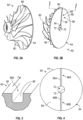
- FIGS. 2A and 2B show front and rear perspective views of a fused rotor.
- compressor rotor 60 includes a base member 64 having a first side 66 and a second side 68 ( FIG. 2B ) defining a circumferential surface (not separately labeled). Second side 68 is opposite to first side 66.
- Base member 64 includes a central opening 70 defining an inner circumferential edge 72.
- Base member 64 also include an outer circumferential edge 76.
- a plurality of blades 80 are provided on first side 66 about central opening 70. As compressor rotor 60 spins, fins 80 develop an airflow that is channeled to select portions of, for example, an aircraft.
- compressor rotor 60 includes a fuse element 86 which takes the form of a groove 88 formed in second side 66 as shown in FIG. 3 .
- Fuse element 86 should be understood to define a built-in failure mechanism for compressor rotor 60. That is, fuse element 86 will cause a crack to propagate through base member 64 under selected operating conditions leading to a failure of compressor rotor 60.
- fuse element 86 is designed to cause a failure if compressor rotor 60 experiences speeds above a selected value. In this manner, compressor rotor 60 is not operated above a selected design speed.
- fuse element 86 includes a first end 94 arranged at inner circumferential edge 72, a second end 96 arranged at outer circumferential edge 74 and an intermediate portion 98. Intermediate portion 98 extends along a radius of base member 64.
- Fuse element 86 is designed to cause a failure of compressor rotor 60 when exposed to hoop stresses, or stresses perceived about a circumference of base member 64 above a selected level. The selected level corresponds to hoop stresses generated at or above a selected rotational speed of compressor rotor 60.
- the particular shape, geometry, and dimensions of groove 88 may vary in different rotor designs and can be optimized according to specifics of particular applications. Similarly, cross-sectional shapes and geometries of fuse groove can be either uniform or non-uniform along their length.
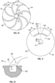
- base member 64 may include a first fuse element 86A and a second fuse element 86B.
- Fuse elements 86A and 86B take the form of first and second grooves 88A and 88B that are aligned with one another and extend across a radius of base member 64.
- Fuse elements 86A and 86B may also be arranged at an angle relative to one another.
- a fuse element 102 defined by a groove 104 in accordance with a non-limiting example includes a first end 106 that is spaced from inner circumferential edge 72, a second end 108 that terminates at outer circumferential edge 74 and an intermediate portion 110 that extends along a portion of a radius of base member 64.
- first end 106 of fuse element 102 is arranged at inner circumferential edge 72 and second end 108 is spaced from outer circumferential edge 74.
- first end 106 of fuse element 102 is spaced from inner circumferential edge 72 and second end 104 is spaced from outer circumferential edge 74.
- FIG. 8 depicts a first fuse element 102A and a second fuse element 102B extending along a common radius of base member 64.
- more than two similar fuse elements can be similarly arranged along a common radius.
- the particular orientation and arrangement of fuse element (s) 102 can vary in order to accommodate a specific failure speed.
- a plurality of fuse element 112 shown in the form of grooves 114 are arrayed about second side 66.
- Each fuse element 112 includes a first end 116 arranged at inner circumferential edge 72, a second end 118 arranged at outer circumferential edge 74, and an intermediate portion 120.
- intermediate portion 120 is substantially linear and extends at an angle relative to a radius of base member 64.
- intermediate portion 120 is shown to be curvilinear.
- a fuse element 154 is shown to extend about a portion of a circumference of second side 68.
- Fuse element 154 takes the form of a curvilinear groove 156 ( FIG. 12 ). that includes a first end 158, a second end 160, and an intermediate portion 162 that is shown to define curvilinear.
- the particular orientation and geometry of intermediate portion 162 may be varied in order to respond or fail when subjected to hoop and/or radial forces on compressor rotor 60 at a selected speed(s).
- Fuse element 154 is designed to fail of promulgate a crack when exposed to selected radial forces on compressor rotor 60.
- first end 158 and second end 160 are equally spaced from inner circumferential edge 72.
- a first fuse element 154A and a second fuse element 154B are formed in base member 64 and arranged opposite to one another.
- a first fuse element 154A, a second fuse element 154B, a third fuse element 154C and a fourth fuse element 154D are formed in base member 64 and circumferentially spaced one from another.
- FIG. 15 depicts a plurality of fuse member 170 arranged about second side 66 in accordance with another non-limiting example.
- Each fuse member 170 is defined by a groove 172 having a first end 174, a second end 175, and an intermediate portion 178.
- intermediate portion 178 is curvilinear. It should however be understood that intermediate portion 178 may be linear.
- first end 174 is spaced from inner circumferential edge 72 a first distance and second end 176 is spaced from inner circumferential edge 72 a second distance that is greater than the first distance.
- FIG. 16 depicts a hybrid failure mode. That is, a first plurality of fuse elements 184 extend along a radius of base member 64 and a second plurality of fuse elements 186 extend along a portion of a circumference of base member 64 in accordance with a non-limiting example. Fuse elements 184 are designed to fail when subjected to hoop forces that exceed a selected magnitude and fuse elements 186 are designed to fail when subjected to radial forces of a selected magnitude.
- the non-limiting examples disclosed herein depict various fuse element arrangements that are designed to respond to select forces on a rotor so as to create a selected operating speed ceiling that that establishes design criteria for surrounding components. It should be understood that while described in terms of a compressor rotor, the non-limiting examples may be utilized in a wide array of systems.
Landscapes
- Engineering & Computer Science (AREA)
- Mechanical Engineering (AREA)
- General Engineering & Computer Science (AREA)
- Health & Medical Sciences (AREA)
- General Health & Medical Sciences (AREA)
- Pulmonology (AREA)
- Aviation & Aerospace Engineering (AREA)
- Fuses (AREA)
Abstract
Description
- Exemplary embodiments pertain to the art of rotating machinery and, more particularly, to a fused rotor for a rotating machine.
- Rotating machines, particularly those that are designed to move air, may include a rotor that supports a number of blades. The rotor is driven to generate an airflow. In certain installations, the rotor may be fused to control a maximum functioning operating speed, i.e., the burst speed. The fuse, which may take the form of an annular notch or a groove, creates an internal stress concentration leading to a built-in failure mechanism at a certain level of load due to rotational inertia. At a certain operating speed or speed range, the stress concentrations in the rotor will generate a fracture at the fuse. Without the built-in failure mechanism, the structure surrounding the rotor would need to be much heavier and potentially more expensive since the size and material properties of the surrounding structure would need to contain the rotor at higher operating speeds.
- The ability of such fuses to generate the fracture with a desired accuracy for a specified speed can be still a challenge. Conventional fuses have relatively simple shapes (e.g., full 360 deg circumferential groove) and therefore lack the desired accuracy to react to specified burst speeds. Therefore, advanced designs of fused rotors with capabilities of enhanced sensitivity of the fracture event to the rotational speed can be an important improvement for such components (rotors) with respect to both performance under service and weight/cost reduction.
- A rotor in accordance with a non-limiting example, includes a base member including a first side, a second side opposite the first side, and a central opening passing through the first side and the second side. The second side includes an outer circumferential edge having a first dimension and the central opening having an inner circumferential edge having a second dimension. A plurality of blades extend outwardly from the first side. The plurality of blades extend about the central opening. A fuse element is formed in the second side and extends along one of a radial direction and a circumferential direction. The fuse element has a length that is less than the first dimension.
- Additionally, or alternatively, in this or other non-limiting examples, the fuse element includes a first end positioned at the inner circumferential edge, a second end positioned at the outer circumferential edge, and an intermediate portion.
- Additionally, or alternatively, in this or other non-limiting examples, the intermediate portion is linear.
- Additionally, or alternatively, in this or other non-limiting examples, the intermediate portion extends along a radius of the second side.
- Additionally, or alternatively, in this or other non-limiting examples, the intermediate portion extends at an angle relative to a radius of the second side.
- Additionally, or alternatively, in this or other non-limiting examples, the intermediate portion is curvilinear.
- Additionally, or alternatively, in this or other non-limiting examples, the fuse element includes a first end positioned at the inner circumferential edge and a second end that is spaced from the outer circumferential edge.
- Additionally, or alternatively, in this or other non-limiting examples, the fuse element includes a first end spaced from the inner circumferential edge and a second end that extends to the outer circumferential edge.
- Additionally, or alternatively, in this or other non-limiting examples, the fuse element includes a first end spaced from the inner circumferential edge, a second end that is spaced from the outer circumferential edge.
- Additionally, or alternatively, in this or other non-limiting examples, the fuse element includes a first fuse element and a second fuse element extending along a radius of the second side.
- Additionally, or alternatively, in this or other non-limiting examples, each of the first fuse element and the second fuse element is spaced from the inner circumferential edge and the outer circumferential edge.
- Additionally, or alternatively, in this or other non-limiting examples, the first fuse element is spaced from the second fuse element.
- Additionally, or alternatively, in this or other non-limiting examples, the first fuse element and the second fuse element are co-linear.
- Additionally, or alternatively, in this or other non-limiting examples, the fuse element includes a first end, a second end, and a curvilinear intermediate portion, the fuse element extending along a circumference of the second side between the inner circumferential edge and the outer circumferential edge.
- Additionally, or alternatively, in this or other non-limiting examples, the first end is spaced from the inner circumferential edge a first distance in a radial direction and the second end is spaced from the inner circumferential edge a second distance in the radial direction, the second distance being equal to the first distance.
- Additionally, or alternatively, in this or other non-limiting examples the first end is spaced from the inner circumferential edge a first distance in a radial direction and the second end is spaced from the inner circumferential edge a second distance in the radial direction, the second distance being greater than the first distance.
- Additionally, or alternatively, in this or other non-limiting examples, the fuse element includes a first fuse element extending along a radius of the second side and a second fuse element extending along a circumference of the second side.
- An aircraft, in accordance with non-limiting examples, includes a fuselage defining a cockpit and a passenger cabin and an air conditioning unit configured to direct conditioned air into one of the cockpit and the passenger cabin. The air conditioning unit includes a rotor having a base member including a first side, a second side opposite the first side, and a central opening passing through the first side and the second side. The second side includes an outer circumferential edge having a first dimension and the central opening has an inner circumferential edge having a second dimension. A plurality of fins extend outwardly from the first side. The plurality of fins extend about the central opening. A fuse element is formed the second side and extends in one of a radial direction and a circumferential direction. The fuse element has a length that is less than the second dimension.
- Additionally, or alternatively, in this or other non-limiting examples, the fuse element includes a first end positioned at the inner circumferential edge, a second end positioned at the outer circumferential edge, and an intermediate portion.
- Additionally, or alternatively, in this or other non-limiting examples, the fuse element includes a first end, a second end, and a curvilinear intermediate portion, the fuse element extending along a circumference of the second side between the inner circumferential edge and the outer circumferential edge.
- The following descriptions should not be considered limiting in any way. With reference to the accompanying drawings, like elements are numbered alike:
-
FIG. 1 depicts cross-sectional side views of an aircraft including a simple air cycle machine as a part of an air conditioning unit having a rotor including a fuse element, in accordance with a non-limiting example; -
FIG. 2A is a front perspective view of a rotor including a fuse element, in accordance with a non-limiting example; -
FIG. 2B is a rear perspective view of the rotor ofFIG. 2A including a fuse element, in accordance with a non-limiting example; -
FIG. 3 is a partial cross-section view of the rotor ofFIG. 2B taken along the line 3-3, in accordance with a non-limiting example; -
FIG. 4 is a rear side view of a rotor including first and second fuse elements, in accordance with a non-limiting example; -
FIG. 5 is a rear side view of a rotor surface including a fuse element, in accordance with a non-limiting example; -
FIG. 6 is a rear side view of a rotor surface including a fuse element, in accordance with a non-limiting example; -
FIG. 7 is a rear side view of a rotor surface including a fuse element, in accordance with a non-limiting example; -
FIG. 8 is a rear side view of a rotor surface including a first fuse element and a second fuse element, in accordance with a non-limiting example; -
FIG. 9 is a rear side view of a rotor including fuse elements, in accordance with a non-limiting example; -
FIG. 10 is a rear side view of a rotor including fuse elements, in accordance with a non-limiting example; -
FIG. 11 is a rear side view of a rotor including a fuse element, in accordance with a non-limiting example; -
FIG. 12 is a partial cross-sectional view of the rotor ofFIG. 11 taken along the line 12-12, in accordance with a non-limiting example; -
FIG. 13 is a rear side view of a rotor including fuse elements, in accordance with a non-limiting example; -
FIG. 14 is a rear side view of a rotor including fuse elements, in accordance with a non-limiting example; -
FIG. 15 is a rear side view of a rotor including fuse elements, in accordance with a non-limiting example; and -
FIG. 16 is a rear side view of a rotor including first fuse elements and second fuse elements, in accordance with a non-limiting example; - A detailed description of one or more embodiments of the disclosed apparatus and method are presented herein by way of exemplification and not limitation with reference to the Figures.
- An aircraft in accordance with a non-limiting example is indicated generally at 10 in
FIG. 1 .Aircraft 10 includes afuselage 12 that defines, in part, acockpit 18 and apassenger cabin 20. Anair cycle machine 24 is supported byfuselage 12 and operable to deliver conditioned air intocockpit 18 and/orpassenger cabin 20.Air cycle machine 24 includes acompressor portion 28 including acompressor inlet 32 and aturbine portion 34 including aturbine outlet 38.Compressor portion 28 includes acompressor rotor 60 andturbine portion 34 includes aturbine rotor 62. At this point, it should be understood thatair cycle machine 24 may take on a variety of forms including air conditioning units, air moving units, and the like, -
Compressor rotor 60 is rotated to draw in a supply of air tocompressor inlet 32. The supply of air is conditioned or passed through a heat exchanger (not shown) and delivered throughturbine outlet 38 intocockpit 18 and/orpassenger cabin 20.Turbine rotor 62 provides a motive force to the airflow passing fromturbine outlet 38. Reference will follow toFIG. 2A and 2B and 3 in describingcompressor rotor 60 in accordance with a non-limiting example. It should be understood thatturbine rotor 62 may include similar structure. -
FIGS. 2A and 2B show front and rear perspective views of a fused rotor. As shown inFIG. 2A ,compressor rotor 60 includes abase member 64 having afirst side 66 and a second side 68 (FIG. 2B ) defining a circumferential surface (not separately labeled).Second side 68 is opposite tofirst side 66.Base member 64 includes acentral opening 70 defining an innercircumferential edge 72.Base member 64 also include an outer circumferential edge 76. A plurality ofblades 80 are provided onfirst side 66 aboutcentral opening 70. Ascompressor rotor 60 spins,fins 80 develop an airflow that is channeled to select portions of, for example, an aircraft. - In a non-limiting example,
compressor rotor 60 includes afuse element 86 which takes the form of agroove 88 formed insecond side 66 as shown inFIG. 3 .Fuse element 86 should be understood to define a built-in failure mechanism forcompressor rotor 60. That is,fuse element 86 will cause a crack to propagate throughbase member 64 under selected operating conditions leading to a failure ofcompressor rotor 60. In a non-limiting example,fuse element 86 is designed to cause a failure ifcompressor rotor 60 experiences speeds above a selected value. In this manner,compressor rotor 60 is not operated above a selected design speed. Failure above the design speed may not only lead to rotor damage but also to lead to damage of surrounding structure and thus create a need for a more robust housing to contain any rotor fragments. Rotor failure can also lead to damage of surrounding components and, thus, create a need for more robust structure in order to contain any rotor fragments. - Referring to
FIG. 2B , in a non-limiting example,fuse element 86 includes afirst end 94 arranged at innercircumferential edge 72, asecond end 96 arranged at outercircumferential edge 74 and anintermediate portion 98.Intermediate portion 98 extends along a radius ofbase member 64.Fuse element 86 is designed to cause a failure ofcompressor rotor 60 when exposed to hoop stresses, or stresses perceived about a circumference ofbase member 64 above a selected level. The selected level corresponds to hoop stresses generated at or above a selected rotational speed ofcompressor rotor 60. The particular shape, geometry, and dimensions ofgroove 88 may vary in different rotor designs and can be optimized according to specifics of particular applications. Similarly, cross-sectional shapes and geometries of fuse groove can be either uniform or non-uniform along their length. - For example, as shown in
FIG. 4 ,base member 64 may include afirst fuse element 86A and asecond fuse element 86B.Fuse elements second grooves base member 64.Fuse elements - Referring to
FIG. 5 , afuse element 102 defined by agroove 104 in accordance with a non-limiting example includes afirst end 106 that is spaced from innercircumferential edge 72, asecond end 108 that terminates at outercircumferential edge 74 and anintermediate portion 110 that extends along a portion of a radius ofbase member 64. InFIG. 6 ,first end 106 offuse element 102 is arranged at innercircumferential edge 72 andsecond end 108 is spaced from outercircumferential edge 74. InFIG. 7 ,first end 106 offuse element 102 is spaced from innercircumferential edge 72 andsecond end 104 is spaced from outercircumferential edge 74.FIG. 8 depicts afirst fuse element 102A and asecond fuse element 102B extending along a common radius ofbase member 64. In other non-limiting example, more than two similar fuse elements can be similarly arranged along a common radius. The particular orientation and arrangement of fuse element (s) 102 can vary in order to accommodate a specific failure speed. - In a non-limiting example shown in
FIG. 9 , a plurality offuse element 112 shown in the form ofgrooves 114 are arrayed aboutsecond side 66. Eachfuse element 112 includes afirst end 116 arranged at innercircumferential edge 72, asecond end 118 arranged at outercircumferential edge 74, and anintermediate portion 120. In a non-limiting example,intermediate portion 120 is substantially linear and extends at an angle relative to a radius ofbase member 64. InFIG. 10 ,intermediate portion 120 is shown to be curvilinear. - In
FIGS. 11 and 12 , afuse element 154 is shown to extend about a portion of a circumference ofsecond side 68.Fuse element 154 takes the form of a curvilinear groove 156 (FIG. 12 ). that includes afirst end 158, asecond end 160, and anintermediate portion 162 that is shown to define curvilinear. The particular orientation and geometry ofintermediate portion 162 may be varied in order to respond or fail when subjected to hoop and/or radial forces oncompressor rotor 60 at a selected speed(s).Fuse element 154 is designed to fail of promulgate a crack when exposed to selected radial forces oncompressor rotor 60. In a non-limiting example,first end 158 andsecond end 160 are equally spaced from innercircumferential edge 72. - In a non-limiting example shown in
FIG. 13 , afirst fuse element 154A and asecond fuse element 154B are formed inbase member 64 and arranged opposite to one another. InFIG. 14 , afirst fuse element 154A, asecond fuse element 154B, athird fuse element 154C and afourth fuse element 154D are formed inbase member 64 and circumferentially spaced one from another. -
FIG. 15 depicts a plurality offuse member 170 arranged aboutsecond side 66 in accordance with another non-limiting example. Eachfuse member 170 is defined by agroove 172 having afirst end 174, a second end 175, and anintermediate portion 178. In a non-limiting example,intermediate portion 178 is curvilinear. It should however be understood thatintermediate portion 178 may be linear. In a non-limiting example,first end 174 is spaced from inner circumferential edge 72 a first distance andsecond end 176 is spaced from inner circumferential edge 72 a second distance that is greater than the first distance. -
FIG. 16 depicts a hybrid failure mode. That is, a first plurality offuse elements 184 extend along a radius ofbase member 64 and a second plurality offuse elements 186 extend along a portion of a circumference ofbase member 64 in accordance with a non-limiting example. Fuseelements 184 are designed to fail when subjected to hoop forces that exceed a selected magnitude and fuseelements 186 are designed to fail when subjected to radial forces of a selected magnitude. The non-limiting examples disclosed herein depict various fuse element arrangements that are designed to respond to select forces on a rotor so as to create a selected operating speed ceiling that that establishes design criteria for surrounding components. It should be understood that while described in terms of a compressor rotor, the non-limiting examples may be utilized in a wide array of systems. - The term "about" is intended to include the degree of error associated with measurement of the particular quantity based upon the equipment available at the time of filing the application.
- The terminology used herein is for the purpose of describing particular embodiments only and is not intended to be limiting of the present disclosure. As used herein, the singular forms "a", "an" and "the" are intended to include the plural forms as well, unless the context clearly indicates otherwise. It will be further understood that the terms "comprises" and/or "comprising," when used in this specification, specify the presence of stated features, integers, steps, operations, elements, and/or components, but do not preclude the presence or addition of one or more other features, integers, steps, operations, element components, and/or groups thereof.
- While the present disclosure has been described with reference to an exemplary embodiment or embodiments, it will be understood by those skilled in the art that various changes may be made and equivalents may be substituted for elements thereof without departing from the scope of the present disclosure. In addition, many modifications may be made to adapt a particular situation or material to the teachings of the present disclosure without departing from the essential scope thereof. Therefore, it is intended that the present disclosure shall not be limited to the particular embodiment disclosed as the best mode contemplated for carrying out this present disclosure, but that the present disclosure will include all embodiments falling within the scope of the claims.
Claims (15)
- A rotor comprising:a base member (64) including a first side (66), a second side (68) opposite the first side, and a central opening (70) passing through the first side and the second side, the second side including an outer circumferential edge (76) having a first dimension and the central opening having an inner circumferential edge (72) having a second dimension;a plurality of blades (80) extending outwardly from the first side, the plurality of blades extending about the central opening; anda fuse element (86, 102, 112, 154, 170) formed in the second side and extending along one of a radial direction and a circumferential direction, the fuse element having a length that is less than the first dimension.
- The rotor according to claim 1, wherein the fuse element (86) includes a first end (94) positioned at the inner circumferential edge (72), a second end (96) positioned at the outer circumferential edge (74), and an intermediate portion (98).
- The rotor according to claim 2, wherein the intermediate portion (98) is linear.
- The rotor according to claim 3, wherein the intermediate portion (98) extends along a radius of the second side (68); or wherein the intermediate portion (98) extends at an angle relative to a radius of the second side (68).
- The rotor according to claim 2, wherein the intermediate portion (98) is curvilinear.
- The rotor according to claim 1, wherein the fuse element (86) includes a first end (94) positioned at the inner circumferential edge (72) and a second end (96) that is spaced from the outer circumferential edge (74); or wherein the fuse element (102) includes a first end (106) spaced from the inner circumferential edge (72) and a second end (108) that extends to the outer circumferential edge (74).
- The rotor according to claim 1, wherein the fuse element (102) includes a first end (106) spaced from the inner circumferential edge (72), a second end (108) that is spaced from the outer circumferential edge (74).
- The rotor according to claim 1, wherein the fuse element (102) includes a first fuse element (102A) and a second fuse element (102B) extending along a radius of the second side (68).
- The rotor according to claim 8, wherein each of the first fuse element (102A) and the second fuse element (102B) is spaced from the inner circumferential edge (72) and the outer circumferential edge (74); and optionally wherein the first fuse (102A) element is spaced from the second fuse element (102B).
- The rotor according to claim 9, wherein the first fuse element (102A) and the second fuse (102B) element are co-linear.
- The rotor according to claim 1, wherein the fuse element (154, 170) includes a first end (158, 174), a second end (160, 175), and a curvilinear intermediate portion (162, 178), the fuse element extending along a circumference of the second side (68) between the inner circumferential edge (72) and the outer circumferential edge (74).
- The rotor according to claim 11, wherein the first end (158) is spaced from the inner circumferential edge (72) a first distance in a radial direction and the second end (160) is spaced from the inner circumferential edge a second distance in the radial direction, the second distance being equal to the first distance; or wherein the first end (174) is spaced from the inner circumferential edge a first distance in a radial direction and the second end (176) is spaced from the inner circumferential edge a second distance in the radial direction, the second distance being greater than the first distance.
- The rotor according to claim 1, wherein the fuse element includes a first fuse element extending along a radius of the second side and a second fuse element extending along a circumference of the second side.
- An aircraft comprising:a fuselage defining a cockpit and a passenger cabin;an air conditioning unit configured to direct conditioned air into one of the cockpit and the passenger cabin, the air conditioning unit including a rotor comprising:a base member including a first side, a second side opposite the first side, and a central opening passing through the first side and the second side, the second side including an outer circumferential edge having a first dimension and the central opening having an inner circumferential edge having a second dimension;a plurality of fins extending outwardly from the first side, the plurality of fins extending about the central opening; anda fuse element formed in the second side and extending along one of a radial direction and a circumferential direction, the fuse element having a length that is less than the second dimension.
- The aircraft according to claim 14, wherein the fuse element includes a first end positioned at the inner circumferential edge, a second end positioned at the outer circumferential edge, and an intermediate portion; or wherein the fuse element includes a first end, a second end, and a curvilinear intermediate portion, the fuse element extending along a circumference of the second side between the inner circumferential edge and the outer circumferential edge.
Applications Claiming Priority (1)
| Application Number | Priority Date | Filing Date | Title |
|---|---|---|---|
| US17/877,093 US11933185B2 (en) | 2022-07-29 | 2022-07-29 | Fused rotor |
Publications (2)
| Publication Number | Publication Date |
|---|---|
| EP4311911A1 true EP4311911A1 (en) | 2024-01-31 |
| EP4311911B1 EP4311911B1 (en) | 2026-05-06 |
Family
ID=87418950
Family Applications (1)
| Application Number | Title | Priority Date | Filing Date |
|---|---|---|---|
| EP23186147.7A Active EP4311911B1 (en) | 2022-07-29 | 2023-07-18 | Fused rotor |
Country Status (2)
| Country | Link |
|---|---|
| US (2) | US11933185B2 (en) |
| EP (1) | EP4311911B1 (en) |
Families Citing this family (1)
| Publication number | Priority date | Publication date | Assignee | Title |
|---|---|---|---|---|
| US11933185B2 (en) | 2022-07-29 | 2024-03-19 | Hamilton Sundstrand Corporation | Fused rotor |
Citations (3)
| Publication number | Priority date | Publication date | Assignee | Title |
|---|---|---|---|---|
| KR20130122832A (en) * | 2012-05-01 | 2013-11-11 | 현대중공업 주식회사 | Impeller |
| US20150226233A1 (en) * | 2012-10-30 | 2015-08-13 | Mitsubishi Heavy Industries Compressor Corporation | Impeller, and rotating machine provided with same |
| EP2960463A1 (en) * | 2013-02-22 | 2015-12-30 | Mitsubishi Heavy Industries, Ltd. | Turbine rotor and turbocharger incorporating such turbine rotor |
Family Cites Families (8)
| Publication number | Priority date | Publication date | Assignee | Title |
|---|---|---|---|---|
| US3175804A (en) | 1963-04-01 | 1965-03-30 | Bendix Corp | Radial-flow turbine safety |
| US3164370A (en) | 1963-07-22 | 1965-01-05 | Bendix Corp | Radial-flow turbine safety |
| US3490748A (en) | 1968-05-14 | 1970-01-20 | Gen Motors Corp | Fragmentation brake for turbines |
| US4890980A (en) * | 1988-08-08 | 1990-01-02 | Ingersoll-Rand Company | Centrifugal pump |
| US5214935A (en) * | 1990-02-20 | 1993-06-01 | Allied-Signal Inc. | Fluid conditioning apparatus and system |
| JP4554189B2 (en) * | 2003-11-26 | 2010-09-29 | 株式会社エンプラス | Centrifugal impeller |
| KR101070904B1 (en) * | 2004-08-20 | 2011-10-06 | 삼성테크윈 주식회사 | Radial turbine wheel |
| US11933185B2 (en) | 2022-07-29 | 2024-03-19 | Hamilton Sundstrand Corporation | Fused rotor |
-
2022
- 2022-07-29 US US17/877,093 patent/US11933185B2/en active Active
-
2023
- 2023-07-18 EP EP23186147.7A patent/EP4311911B1/en active Active
-
2024
- 2024-03-18 US US18/608,521 patent/US12553363B2/en active Active
Patent Citations (3)
| Publication number | Priority date | Publication date | Assignee | Title |
|---|---|---|---|---|
| KR20130122832A (en) * | 2012-05-01 | 2013-11-11 | 현대중공업 주식회사 | Impeller |
| US20150226233A1 (en) * | 2012-10-30 | 2015-08-13 | Mitsubishi Heavy Industries Compressor Corporation | Impeller, and rotating machine provided with same |
| EP2960463A1 (en) * | 2013-02-22 | 2015-12-30 | Mitsubishi Heavy Industries, Ltd. | Turbine rotor and turbocharger incorporating such turbine rotor |
Also Published As
| Publication number | Publication date |
|---|---|
| US12553363B2 (en) | 2026-02-17 |
| US20240218807A1 (en) | 2024-07-04 |
| US11933185B2 (en) | 2024-03-19 |
| US20240035394A1 (en) | 2024-02-01 |
| EP4311911B1 (en) | 2026-05-06 |
Similar Documents
| Publication | Publication Date | Title |
|---|---|---|
| EP3284963B1 (en) | High load capacity hybrid foil bearing | |
| EP3073121B1 (en) | Bearing cooling flow and energy recovery systems | |
| US8876472B2 (en) | Turbine wheel having de-tuned blades and including a damper device | |
| US2714499A (en) | Blading for turbomachines | |
| EP4311911B1 (en) | Fused rotor | |
| US6457941B1 (en) | Fan rotor with construction and safety performance optimization | |
| US9267514B2 (en) | Bearing cooling control in an air cycle machine | |
| EP3452700A1 (en) | Metallic leading edge for a composite fan blade | |
| CN107345528B (en) | Air cycle machine fan and compressor housing | |
| EP3054088B1 (en) | Gas turbine engine rotor disk balancing | |
| CN102536893A (en) | Air cycle machine compressor rotor | |
| US9989070B2 (en) | Air cycle machine strut plate assembly | |
| CN104584390B (en) | Rotor of electrical machine, and electrical machine | |
| US8382426B2 (en) | High-speed air spindle | |
| US20140338193A1 (en) | Balancing method | |
| US9914542B2 (en) | Ram air fan housing | |
| US10829241B2 (en) | Structurally improved ram fan inlet shroud | |
| EP3170982A1 (en) | Rotor assembly for use in a turbofan engine and method of assembling | |
| CN109891070A (en) | Combined flow turbine impeller | |
| US20160319836A1 (en) | Axial flow fan with blades twisted according to a blade pitch ratio that decreases (quasi) linearly with the radial position | |
| US20180328375A1 (en) | Compressor | |
| CN106837434B (en) | Turbine thrust shaft for air bearing cooling | |
| EP4439036A1 (en) | Test blade for gas turbine engine and method of making | |
| US20120156009A1 (en) | Fan shield and bearing housing for air cycle machine | |
| GB2105790A (en) | Balanced bladed rotor |
Legal Events
| Date | Code | Title | Description |
|---|---|---|---|
| PUAI | Public reference made under article 153(3) epc to a published international application that has entered the european phase |
Free format text: ORIGINAL CODE: 0009012 |
|
| STAA | Information on the status of an ep patent application or granted ep patent |
Free format text: STATUS: THE APPLICATION HAS BEEN PUBLISHED |
|
| AK | Designated contracting states |
Kind code of ref document: A1 Designated state(s): AL AT BE BG CH CY CZ DE DK EE ES FI FR GB GR HR HU IE IS IT LI LT LU LV MC ME MK MT NL NO PL PT RO RS SE SI SK SM TR |
|
| STAA | Information on the status of an ep patent application or granted ep patent |
Free format text: STATUS: REQUEST FOR EXAMINATION WAS MADE |
|
| 17P | Request for examination filed |
Effective date: 20240729 |
|
| RBV | Designated contracting states (corrected) |
Designated state(s): AL AT BE BG CH CY CZ DE DK EE ES FI FR GB GR HR HU IE IS IT LI LT LU LV MC ME MK MT NL NO PL PT RO RS SE SI SK SM TR |
|
| RIC1 | Information provided on ipc code assigned before grant |
Ipc: F01D 5/04 20060101AFI20251125BHEP |
|
| GRAP | Despatch of communication of intention to grant a patent |
Free format text: ORIGINAL CODE: EPIDOSNIGR1 |
|
| STAA | Information on the status of an ep patent application or granted ep patent |
Free format text: STATUS: GRANT OF PATENT IS INTENDED |
|
| INTG | Intention to grant announced |
Effective date: 20260120 |
|
| GRAS | Grant fee paid |
Free format text: ORIGINAL CODE: EPIDOSNIGR3 |
|
| GRAA | (expected) grant |
Free format text: ORIGINAL CODE: 0009210 |
|
| STAA | Information on the status of an ep patent application or granted ep patent |
Free format text: STATUS: THE PATENT HAS BEEN GRANTED |
|
| AK | Designated contracting states |
Kind code of ref document: B1 Designated state(s): AL AT BE BG CH CY CZ DE DK EE ES FI FR GB GR HR HU IE IS IT LI LT LU LV MC ME MK MT NL NO PL PT RO RS SE SI SK SM TR |
|
| REG | Reference to a national code |
Ref country code: CH Ref legal event code: F10 Free format text: ST27 STATUS EVENT CODE: U-0-0-F10-F00 (AS PROVIDED BY THE NATIONAL OFFICE) Effective date: 20260506 Ref country code: GB Ref legal event code: FG4D |