EP4311768A1 - Spoiler actuator - Google Patents
Spoiler actuator Download PDFInfo
- Publication number
- EP4311768A1 EP4311768A1 EP22306118.5A EP22306118A EP4311768A1 EP 4311768 A1 EP4311768 A1 EP 4311768A1 EP 22306118 A EP22306118 A EP 22306118A EP 4311768 A1 EP4311768 A1 EP 4311768A1
- Authority
- EP
- European Patent Office
- Prior art keywords
- cam
- rod
- output rod
- housing
- output
- Prior art date
- Legal status (The legal status is an assumption and is not a legal conclusion. Google has not performed a legal analysis and makes no representation as to the accuracy of the status listed.)
- Granted
Links
Images



Classifications
-
- B—PERFORMING OPERATIONS; TRANSPORTING
- B64—AIRCRAFT; AVIATION; COSMONAUTICS
- B64C—AEROPLANES; HELICOPTERS
- B64C13/00—Control systems or transmitting systems for actuating flying-control surfaces, lift-increasing flaps, air brakes, or spoilers
- B64C13/24—Transmitting means
- B64C13/38—Transmitting means with power amplification
- B64C13/50—Transmitting means with power amplification using electrical energy
-
- B—PERFORMING OPERATIONS; TRANSPORTING
- B64—AIRCRAFT; AVIATION; COSMONAUTICS
- B64C—AEROPLANES; HELICOPTERS
- B64C5/00—Stabilising surfaces
- B64C5/10—Stabilising surfaces adjustable
-
- F—MECHANICAL ENGINEERING; LIGHTING; HEATING; WEAPONS; BLASTING
- F16—ENGINEERING ELEMENTS AND UNITS; GENERAL MEASURES FOR PRODUCING AND MAINTAINING EFFECTIVE FUNCTIONING OF MACHINES OR INSTALLATIONS; THERMAL INSULATION IN GENERAL
- F16H—GEARING
- F16H25/00—Gearings comprising primarily only cams, cam-followers and screw-and-nut mechanisms
- F16H25/18—Gearings comprising primarily only cams, cam-followers and screw-and-nut mechanisms for conveying or interconverting oscillating or reciprocating motions
- F16H25/20—Screw mechanisms
-
- F—MECHANICAL ENGINEERING; LIGHTING; HEATING; WEAPONS; BLASTING
- F16—ENGINEERING ELEMENTS AND UNITS; GENERAL MEASURES FOR PRODUCING AND MAINTAINING EFFECTIVE FUNCTIONING OF MACHINES OR INSTALLATIONS; THERMAL INSULATION IN GENERAL
- F16H—GEARING
- F16H25/00—Gearings comprising primarily only cams, cam-followers and screw-and-nut mechanisms
- F16H25/18—Gearings comprising primarily only cams, cam-followers and screw-and-nut mechanisms for conveying or interconverting oscillating or reciprocating motions
- F16H25/20—Screw mechanisms
- F16H25/24—Elements essential to such mechanisms, e.g. screws, nuts
- F16H25/2454—Brakes; Rotational locks
-
- F—MECHANICAL ENGINEERING; LIGHTING; HEATING; WEAPONS; BLASTING
- F16—ENGINEERING ELEMENTS AND UNITS; GENERAL MEASURES FOR PRODUCING AND MAINTAINING EFFECTIVE FUNCTIONING OF MACHINES OR INSTALLATIONS; THERMAL INSULATION IN GENERAL
- F16H—GEARING
- F16H25/00—Gearings comprising primarily only cams, cam-followers and screw-and-nut mechanisms
- F16H25/18—Gearings comprising primarily only cams, cam-followers and screw-and-nut mechanisms for conveying or interconverting oscillating or reciprocating motions
- F16H25/20—Screw mechanisms
- F16H2025/2062—Arrangements for driving the actuator
- F16H2025/2081—Parallel arrangement of drive motor to screw axis
Definitions
- the present document relates to an electromechanical actuator with an anti-extension device.
- Actuators are widely used in aircraft.
- electromechanical actuators EMAs
- EMAs electromechanical actuators
- Weight considerations are often paramount in designing aircraft components and so designing lighter weight components is generally desired for aerospace applications.
- an electromechanical actuator comprising: a motor; a gearbox; an anti-extension device mounted between the motor and the gearbox; wherein the motor and anti-extension device are mounted on a housing of the actuator; a screw shaft; a nut mounted on the screw shaft; an output rod connected to the nut, the output rod having a linear range of motion defined between full extension of the output rod at a first end point and full retraction of the output rod at a second end point; wherein the screw shaft, nut, and output rod are located in a cavity of the housing; wherein the output rod and nut are held against rotation relative to the housing, such that rotation of the screw shaft drives the output rod to move linearly within the housing; wherein the anti-extension device comprises: a ratchet wheel mounted on a shaft arranged to be driven by the motor; a pivotable rod comprising a pawl; the pivotable rod being pivotable between a first position in which the pawl engages with the ratchet wheel to
- the anti-extension device is automatically disabled such that the pawl does not engage with the ratchet wheel.
- the housing may comprise a housing connection end for connecting the actuator to an airframe; and the output rod may comprise an output rod connection end for connecting the actuator to a spoiler.
- the cam may have a curved or chamfered end; and/or the end of the output rod may be curved or chamfered.
- the anti-extension device may be directly connected to the gearbox. That is, the actuator may lack a torque limiter between the anti-extension device and the gearbox, for example.
- the anti-extension device may further comprise a solenoid having a movable output; wherein, when the axial end of the output rod is between the intermediate point and the first end point, movement of the movable output moves the pivotable rod to the second position.
- the solenoid may be used to control the position of the pivotable rod and pawl relative to the ratchet wheel.
- the electromechanical actuator may optionally not comprise a torque limiter at any location along a load path between the motor and the screw shaft.
- the existence of the cam and its interaction with the output rod and the anti-extension device may eliminate the need for any torque limiter, such as is often provided on prior art actuators.
- an aircraft comprising an airframe and a flight surface, and the electromechanical actuator as described hereinabove.
- the housing of the electromechanical actuator is connected to the airframe and the output rod of the electromechanical actuator is connected to the flight surface, such that the position of the output rod relative to the housing controls an angular position of the flight surface relative to the airframe.
- the actuator may be arranged such that when the end of the output rod is at a second intermediate axial point, the flight surface is at an angle of zero degrees relative to the airframe.
- the second intermediate axial point may be coincident with the predetermined intermediate point, such that the output rod bears against the cam only when the spoiler at an angle of greater than zero degrees relative to the airframe.
- the second intermediate point may be at a different axial location from the predetermined intermediate point.
- the second intermediate point may be located axially between the predetermined intermediate point and the second end point.
- the flight surface may be is a spoiler.
- FIG. 1 shows a known design of electromechanical actuator (EMA) 10.
- the EMA 10 comprises a motor 12 that is connected, in sequence, to an anti-extension device 14, a torque-limiter 16, and to a gearbox 18. These components 12,14,16,18 are mounted to an external surface of a housing 20.
- the gearbox 18 extends through the housing and drives a screw shaft 22 in rotation.
- the screw shaft 22 extends within the housing 20 along an axis X.
- a nut 24 is mounted on the screw shaft and an output rod 26 is connected to the radially-outer side of the nut 24.
- the output rod 26 is held against rotation relative to the housing 20, e.g. via splines (not shown), and this holds the nut 24 against rotation relative to the housing 20.
- the output rod 26 has a connection end 28 for connection to a spoiler 34.
- the housing 20 has a housing connection end 30 whereby the housing 20 (and EMA 10 as a whole) may be connected to an airframe 32.
- the motor 12 rotates an output shaft (not shown) that turns the gears of the gearbox 18 which causes the screw shaft 22 to rotate within the housing 20.
- the output shaft of the motor 20 may extend all the way through the anti-extension device 14 and into one side of the torque limiter 16. Another shaft (not shown) extends from the other side of the torque limiter 16 into the gearbox 18.
- the anti-extension device 14 may contain its own shaft (e.g. shaft 56), and the motor output shaft connects to the anti-extension device's shaft 56 (e.g. via splines), and the anti-extension device's shaft 56 may connect to a first side of the torque limiter 16, so that torque from the motor 12 is transmitted to the gearbox.
- Figure 2A shows a cross-section of the known anti-extension device 14. This cross-sectional drawing further shows the housing 20, upon which the anti-extension device 14 is mounted, and also shows the output rod 26 (inside the housing 20) in cross-section.
- the anti-extension device 14 comprises a solenoid 40 having a movable output 42 that bears against a first end of a pivotable rod 44.
- the pivotable rod 44 may be pivoted around a pivot point 46.
- a second end of the pivotable rod 44 abuts a pusher 48.
- the pusher 48 is biased by a spring 50.
- the pivotable rod 44 further comprises a pawl 52 that is arranged adjacent to a ratchet wheel 54.
- the ratchet wheel 54 is fixedly mounted on a shaft 56.
- an output shaft of the motor 12 connects to the shaft 56 (or, as above, the shaft 56 may itself be the output shaft of the motor 12), such that torque from the motor 12 turns the shaft 56 and thus turns the ratchet wheel 54 if possible.
- the shaft 56 also connects (or extends into) the torque limiter 16.
- the pivotable rod 44 is arranged such that, in the first position (i.e. when the solenoid 40 is not energized, shown in Figure 2A ), the pawl 52 abuts the ratchet wheel 54 and, through engagement with teeth of the ratchet wheel 54, prevents rotation of the ratchet wheel in one direction of rotation.
- Figure 2B shows the second position (i.e. when the solenoid is energized), wherein the pivotable rod 44 has been pushed by the movable output 42 to a position where the pawl 52 does not abut the ratchet wheel 54, and the ratchet wheel 54 and shaft 56 may rotate in either direction of rotation.
- the force from the movable output 42 to pivot the rod 44 also compresses the spring 50.
- the solenoid 40 is later de-energised, the force from the spring 50 pushes the pivotable rod 44 back to the first position, whereupon the pawl 52 reengages the ratchet wheel 54.
- the motor 12 may be used to drive the output rod 26 in extension to a first desired position.
- the EMA 10 may then engage the anti-extension device by de-energising the solenoid 40.
- This causes the pawl 52 to engage the ratchet wheel 54 and prevent rotation of the shaft 56 in a first direction of rotation.
- This first direction corresponds to extension of the output rod 26 out from the housing 20. That is, when aerodynamic forces on the spoiler 34 seek to pull the output rod 26 further out from the housing 20, this linear force is converted, by the interaction of the nut 24 with the screw shaft 22, into a torque on the screw shaft 22.
- This torque is then transmitted, via the gearbox 18 and torque limiter 16 into the anti-extension device 14. There the torque is reacted by the engagement of the pawl 52 with the ratchet wheel 54. This prevents the torque from being transmitted back into the motor 12 which could damage the motor 12.
- an aircraft spoiler may be extended to negative angular positions so that it follows an extended flap of the aircraft wing. This provides a largely continuous surface between a leading edge of the wing and the trailing edge of the flap. In the negative angular positions, the anti-extension mode may be active so that the spoiler cannot move from its negative angular position towards the neutral position/towards a positive position.
- the torque limiter 16 limits the maximum torque transmitted between the gearbox 18 and the anti-extension device 16. The skilled reader will appreciate that, when the torque limit of the torque limiter 16 is exceeded, the torque limiter will allow rotation on the gearbox 18 side even while the shaft 56 on the side of the anti-extension device 14 is prevented from turning. This thus allows some rotation of the screw shaft 22 and, ultimately, extension of the spoiler 34 towards the neutral position.
- EMA 100 A new design of EMA 100 will now be described in relation to Figures 3 to 8 .
- the new design of EMA 100 shares several similarities with the known EMA 10 design described hereinabove, and where like components are used, the same reference numeral will be used.
- the EMA 100 shown in Figure 3 comprises a motor 12 and a new design of anti-extension device 140 having a cam 142.
- the anti-extension device 140 connects directly between the motor 12 and a gearbox 18. That is, compares to the known EMA 10 described above, there is no torque-limiter 16 present in the new design of EMA 100. Removal of the torque limiter may reduce the overall weight of the new design of EMA 100 compared to the known EMA 10 described above.
- the motor 12, anti-extension device 140, and gearbox 18 are mounted to a housing 200.
- the housing 200 may be identical to the housing 20 of Figure 1 except that the housing 200 comprises an aperture 202 through which the cam 142 extends.
- a housing 20 from the known design of EMA 10 may be simply converted into the new design of housing 200 simply by drilling a hole through the housing 20, to form the aperture 202 that receives the cam 142.
- the aperture 202 allows the cam 142 to extend from the anti-extension device 140, through the housing 200, and into a cavity 204 inside the housing, in which the output rod 26 moves.
- the cam 142 is movable along a second axis Y between a first cam position (shown in Figure 4 ) and a second cam position (shown in Figure 6 ).
- the second axis Y is non-parallel with the first axis X and may be generally perpendicular to the first axis X.
- the output rod 26 has a connection end 28 for connection to a spoiler 34 and the housing 200 has a housing connection end 30 where the housing (and EMA 100 as a whole) may be connected to the airframe 32.
- the anti-extension functionality of the anti-extension device 140 is automatically disabled, i.e. the anti-extension device 140 does not prevent extension of the output rod 26 while the anti-extension device is disabled, regardless of whether the solenoid 40 is energized or not, in the manner discussed in greater detail below.
- the gearbox 18 transmits torque from the motor 12 to turn the screw shaft 22.
- the nut 24 is mounted on the screw shaft 22 and the nut connects to the output rod 26 which, like before, is held against rotation relative to the housing 200.
- Figure 4 shows a cross-sectional view of the new design of anti-extension device 140.
- the new anti-extension device 14 shares a number of similar components to the anti-extension device 14 described above in relation to Figure 2 , and where like components are used, the same reference numeral will be used.
- the anti-extension device 140 comprises the solenoid 40 having the movable output 42 that bears against the first end of a pivotable rod 44.
- the pivotable rod 44 may be pivoted around the pivot point 46.
- the anti-extension device While the cam 142 is not pushed into the anti-extension device 140 by the output rod 26, the anti-extension device is not disabled.
- the position of the pawl 52 with respect to the ratchet wheel 54 is under the control of the solenoid 40. That is, when the solenoid 40 is energized, the movable output moves towards the pivotable rod 44 and pivots the rod, from a first rod position to a second rod position, said pivoting being about the pivot point 46 and against the bias from the spring 50.
- the solenoid When the solenoid is de-energized, the bias from the spring 50 pivots the pivotable rod back to its initial first rod position.
- the solenoid 40 controls whether the anti-extension device acts to prevent extension of the output rod 26 or not.
- a second end of the pivotable rod 44 abuts the cam 142.
- the cam 142 comprises a first flange 144 and a second flange 146.
- the spring 50 biases the cam 142 outward from the anti-extension device 140 (and therefore, biases the cam 142 generally in towards the axis X, into the cavity 204 of the housing 200) - this position is the first cam position of the cam 142.
- the second end of the pivotable rod 44 is located between the first and second flanges 144,146 of the cam 142, such that movement of the cam 142 in either direction along the second axis Y controls the angular position of the pivotable rod 44 about the pivot point 46.
- the pivotable rod 44 may be moved by the solenoid 40 such that the pawl 52 is disengaged from the ratchet wheel 54.
- the solenoid 40 moves the pivotable rod 44 to such a disengaged rod position, the second end of the pivotable rod 44 presses against the first flange 144 and, against the bias of the spring 50, pulls the cam 142 into the anti-extension device 140.
- the output rod 26 is linearly movable relative to the housing 200 along a range of motion depicted by the line A-C in Figure 3 .
- Point A corresponds to full extension of the output rod 26, i.e. out from the housing 200
- point C corresponds to full retraction of the output rod 26. More precisely, point A may correspond to a first axial position of an end 26b of the output rod 26 within the housing 200, and point C may correspond to a second axial position of the end 26b of the output rod 26 within the housing 200.
- the linear position of the output rod 26 relative to the housing 200 sets the angle of the spoiler 34 relative to the airframe 32.
- Various angles of the spoiler 34 are shown in Figure 7 .
- the EMA 100 may be arranged such that a given axial position B of the output rod 26 within the housing 200 corresponds to a 0° position of the spoiler 34.
- the position B may be located between the ends A and C of the range of motion available to the output rod 26. That is, the EMA 100 may be arranged to allow the spoiler 34 to be moved within a range of positive angles, a range of negative angles, and to be held at a 0° position.
- the spoiler 34 may be movable between +15° and -50°, where +15° of the spoiler 34 corresponds to the output rod 26 being at full retraction at position C, and where -50° of the spoiler 34 corresponds to the output rod 26 being at full extension at position A.
- the spoiler 24 When the spoiler 34 is at positive angular positions, i.e. its angular position is >0°, the spoiler 24 is said to be operating in the "droop area".
- the droop area of the spoiler 34 thus corresponds to the output rod 26 being in the linear range of ⁇ B and ⁇ C relative to the housing 200.
- the output rod 26 is at a linear position within the cavity 204 where the output rod 26 does not abut against the cam 142.
- the angled end 148 may be a curved end, e.g. hemispherical, or may be e.g. chamfered (as shown in Figure 8 ).
- the angled end 148 allows the cam 142 to ride up onto a radially outer surface 26a of the output rod 26 when, during retraction of the output rod 26, an end 26b of the output rod 26 first comes into alignment with the cam 142.
- the end 26b of the output rod 26 may also be chamfered or curved (as shown in Figure 8 ) to allow a smooth motion of pushing the cam 142 out from the cavity 204.
- this Figure depicts a cross-section of the EMA 100 where the output rod 26 is retracted sufficiently far into the housing 200 that the cam 142 is pressed away from the first axis X and into the anti-extension device 140.
- An intermediate axial position D of the output rod 26, between the end points A and C, is defined as the point where the end 26b of the output rod 26 first bears against the angled end 148 of the cam 142 and has pushed the cam 142 into the anti-extension device 140 sufficiently far so as to cause the pawl 52 to disengage from ratchet wheel 54.
- the anti-extension device 140 is disabled. That is, in this cam position, regardless of whether the solenoid 40 is energized or not, the pawl 52 does not contact the ratchet wheel 54 and thus the shaft 56 is free to rotate in either direction.
- Intermediate axial position D (where the end 26b of the output rod 26 first meets the cam 142) may be identical to position B (where the spoiler is at 0°), but this is not essential.
- axial positions D and B are identical, i.e. at the same axial location along axis X, this means that the anti-extension device 140 is disabled whenever the spoiler 34 is at 0° or higher.
- the anti-extension device 140 is no longer disabled and the engagement/disengagement of the pawl 52 from the ratchet wheel 54 is again under the control of the solenoid 40.
- intermediate axial position D is offset from position B.
- the intermediate axial position D may be set at a spoiler angle of +10°.
- the anti-extension device 140 will be disabled whenever the spoiler 34 is at a 10° angle or higher.
- Figure 6 shows the cross-section of the anti-extension device 140 when the output rod 26 is at the rod position shown in Figure 5 , i.e. where the output rod 26 has pushed the cam 142 in to the anti-extension device 140.
- the first flange 144 has compressed the spring and the second flange 146 has pushed the second end of the pivotable rod 44 to the second rod position wherein the pawl 52 does not engage the ratchet wheel 54.
- the movable output 42 of the solenoid 40 is still in its original position (i.e. the solenoid 40 is not energized) and the movable output 42 is not presently in abutment with the pivotable rod 44.
- the pawl 52 is disengaged from the ratchet wheel 52 regardless of whether or not the solenoid 40 is energized. That is, the anti-extension device 140 is automatically disabled whenever the output rod 26 is pressing the cam 142 into the anti-extension device 140.
- the solenoid 40 determines whether the anti-extension device 140 is engaged or not.
- the anti-extension device 140 is automatically disabled, by virtue of the cam 142 being pushed into the anti-extension device 140 and thereby disengaging the pawl 52 from the ratchet wheel 54.
- Figure 8 depicts various alternative shapes for the angled end 148 of the cam 142 and for the end 26b of the output rod 26.
- Figure 8 shows: a chamfered end of the output rod 26; a rounded end of the output rod 26; and a chamfered end of the cam 142.
- the EMA 100 may use any combination of the various end shapes depicted in any of the Figures for the cam 142 and for the output rod 26.
- Figure 9 shows an aircraft 33 having the spoiler 34.
- the aircraft 33 comprises the airframe 32 and the EMA may be connected to any suitable part of the airframe, such as inside of the wing or on the underside of the wing, near the spoiler 34.
- the electromechanical actuator 100 may be used to control different control surfaces of an aircraft, including flaps, slats, ailerons etc.
- Reference numerals (known) EMA 10 Motor 12 (known) Anti-extension device 14 Torque limiter 16 Gearbox 18 Housing 20 Screw shaft 22 Nut 24 Output rod 26 Outer surface (of output rod) 26a End (of output rod) 26b Connection end (of output rod) 28 Housing connection end 30 Airframe 32 Aircraft 33 Spoiler 34 Solenoid 40 Movable output (of solenoid) 42 Pivotable rod 44 Pivot point (of pivotable rod) 46 Pusher 48 Spring 50 Pawl (on pivot rod) 52 Ratchet wheel 54 Shaft 56 (new) anti-extension device 140 Cam 142 First flange (of cam) 144 Second flange (of cam) 146 End (of cam) 148 (new) housing 200 Aperture (of new housing) 202 Cavity (in new housing) 204 End of range of motion (fully extended)
Landscapes
- Engineering & Computer Science (AREA)
- General Engineering & Computer Science (AREA)
- Mechanical Engineering (AREA)
- Aviation & Aerospace Engineering (AREA)
- Automation & Control Theory (AREA)
- Transmission Devices (AREA)
Abstract
Description
- The present document relates to an electromechanical actuator with an anti-extension device.
- Actuators are widely used in aircraft. In particular, electromechanical actuators (EMAs) are becoming more widely used for controlling the position of flaps, slats, a spoilers of aircraft. It is known to locate anti-extension device between a gearbox and a motor of the actuator, wherein when the anti-extension device is activated, the motor is protected against torque that is feeding-back through the system, e.g. resulting from loads on the flap, slat, or spoiler. Weight considerations are often paramount in designing aircraft components and so designing lighter weight components is generally desired for aerospace applications.
- According to a first aspect, there is provided an electromechanical actuator comprising: a motor; a gearbox; an anti-extension device mounted between the motor and the gearbox; wherein the motor and anti-extension device are mounted on a housing of the actuator; a screw shaft; a nut mounted on the screw shaft; an output rod connected to the nut, the output rod having a linear range of motion defined between full extension of the output rod at a first end point and full retraction of the output rod at a second end point; wherein the screw shaft, nut, and output rod are located in a cavity of the housing; wherein the output rod and nut are held against rotation relative to the housing, such that rotation of the screw shaft drives the output rod to move linearly within the housing; wherein the anti-extension device comprises: a ratchet wheel mounted on a shaft arranged to be driven by the motor; a pivotable rod comprising a pawl; the pivotable rod being pivotable between a first position in which the pawl engages with the ratchet wheel to prevent rotation of the ratchet wheel in one direction of rotation, and a second position in which the pawl does not prevent rotation of the ratchet wheel; a cam connected to the pivotable rod, the cam movable between a first cam position and a second cam position, wherein the cam is biased by a spring towards the first cam position in which a portion of the cam extends through an aperture in the housing and into the cavity; wherein in the second cam position, the cam holds the pivotable rod at the second position in which the pawl does not prevent rotation of the ratchet wheel; wherein, when an axial end of the output rod is at a predetermined intermediate point or between the intermediate point and the second end point, the cam is moved to the second cam position by an outer surface of the output rod bearing against the cam; and wherein when the axial end of the output rod is between the intermediate point and the first end point, the output rod does not bear against the cam.
- In this manner, whenever the output rod is sufficiently retracted into the housing, the anti-extension device is automatically disabled such that the pawl does not engage with the ratchet wheel.
- The housing may comprise a housing connection end for connecting the actuator to an airframe; and the output rod may comprise an output rod connection end for connecting the actuator to a spoiler.
- The cam may have a curved or chamfered end; and/or the end of the output rod may be curved or chamfered.
- This may allow the cam to be moved smoothly into the anti-extension device when the output rod presses the cam thereinto.
- The anti-extension device may be directly connected to the gearbox. That is, the actuator may lack a torque limiter between the anti-extension device and the gearbox, for example.
- The anti-extension device may further comprise a solenoid having a movable output; wherein, when the axial end of the output rod is between the intermediate point and the first end point, movement of the movable output moves the pivotable rod to the second position.
- That is, when the output rod is not pressing the cam into the anti-extension device, the solenoid may be used to control the position of the pivotable rod and pawl relative to the ratchet wheel.
- In such examples, when an axial end of the output rod is at the predetermined intermediate point or between the intermediate point and the second end point, movement of the movable output does not affect the position of the pivotable rod.
- The electromechanical actuator may optionally not comprise a torque limiter at any location along a load path between the motor and the screw shaft. The existence of the cam and its interaction with the output rod and the anti-extension device may eliminate the need for any torque limiter, such as is often provided on prior art actuators.
- According to a second aspect, there is provided an aircraft comprising an airframe and a flight surface, and the electromechanical actuator as described hereinabove. In this aspect, the housing of the electromechanical actuator is connected to the airframe and the output rod of the electromechanical actuator is connected to the flight surface, such that the position of the output rod relative to the housing controls an angular position of the flight surface relative to the airframe.
- The actuator may be arranged such that when the end of the output rod is at a second intermediate axial point, the flight surface is at an angle of zero degrees relative to the airframe.
- The second intermediate axial point may be coincident with the predetermined intermediate point, such that the output rod bears against the cam only when the spoiler at an angle of greater than zero degrees relative to the airframe.
- The second intermediate point may be at a different axial location from the predetermined intermediate point. Optionally, the second intermediate point may be located axially between the predetermined intermediate point and the second end point.
- The flight surface may be is a spoiler.
- Certain embodiments will now be described in greater detail by way of example only and with reference to the accompanying drawings in which:
-
Figure 1 shows a known design of EMA for a spoiler, the EMA having an anti-extension device; -
Figure 2A shows a cross-section of the known EMA in the anti-extension mode; -
Figure 2B shows a cross-section of the known EMA in an active mode; -
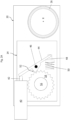
Figure 3 shows a cross-section of a new design of EMA for a spoiler, the new EMA having a new design of anti-extension device; -
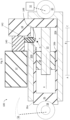
Figure 4 shows a cross-section of the new anti-extension device; -
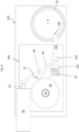
Figure 5 shows a second cross-section of the new EMA; -
Figure 6 shows a second cross-section of the new anti-extension device; -
Figure 7 shows positions of the spoiler controlled by the EMA; -
Figure 8 shows various end profiles of a cam and of an output rod of the new EMA; and -
Figure 9 shows an aircraft. -
Figure 1 shows a known design of electromechanical actuator (EMA) 10. The EMA 10 comprises amotor 12 that is connected, in sequence, to ananti-extension device 14, a torque-limiter 16, and to agearbox 18. Thesecomponents housing 20. Thegearbox 18 extends through the housing and drives ascrew shaft 22 in rotation. Thescrew shaft 22 extends within thehousing 20 along an axis X. Anut 24 is mounted on the screw shaft and anoutput rod 26 is connected to the radially-outer side of thenut 24. Theoutput rod 26 is held against rotation relative to thehousing 20, e.g. via splines (not shown), and this holds thenut 24 against rotation relative to thehousing 20. Theoutput rod 26 has aconnection end 28 for connection to aspoiler 34. Thehousing 20 has a housing connection end 30 whereby the housing 20 (and EMA 10 as a whole) may be connected to anairframe 32. - In normal operation, the
motor 12 rotates an output shaft (not shown) that turns the gears of thegearbox 18 which causes thescrew shaft 22 to rotate within thehousing 20. In some examples, the output shaft of themotor 20 may extend all the way through theanti-extension device 14 and into one side of thetorque limiter 16. Another shaft (not shown) extends from the other side of thetorque limiter 16 into thegearbox 18. In other examples, theanti-extension device 14 may contain its own shaft (e.g. shaft 56), and the motor output shaft connects to the anti-extension device's shaft 56 (e.g. via splines), and the anti-extension device'sshaft 56 may connect to a first side of thetorque limiter 16, so that torque from themotor 12 is transmitted to the gearbox. - As the
nut 24 is held against rotation relative to thehousing 20, rotation of thescrew shaft 22 within thehousing 20 causes thenut 24 to translate linearly along the axis X, which thus causes theoutput rod 26 to translate linearly relative to thehousing 20. In this manner, rotational output from themotor 22 is converted into a linear output of the EMA 10, by theoutput rod 26 moving in and out of thehousing 20. When used on an aircraft (e.g. aircraft 33 shown inFig 9 ), this linear output of the EMA 10 controls the position of thespoiler 34 relative to theairframe 32. - During flight, there may be significant aerodynamic forces on the
spoiler 34. These forces may attempt to pull theoutput rod 26 further out from thehousing 20, or push theoutput rod 26 into thehousing 20. Due to the interaction of thenut 24 with thescrew shaft 22, these linear forces on theoutput rod 26 are converted into torque in thescrew shaft 22, which torque is transmitted, via thegearbox 18, into thetorque limiter 16 and theanti-extension device 14. Theanti-extension device 14 is designed to, when activated, react this torque and thereby prevent rotation of thescrew shaft 22 that would allow theoutput rod 26 to extend further out of thehousing 20. This operation is described in more detail below, in relation toFigure 2 . -
Figure 2A shows a cross-section of the knownanti-extension device 14. This cross-sectional drawing further shows thehousing 20, upon which theanti-extension device 14 is mounted, and also shows the output rod 26 (inside the housing 20) in cross-section. - The
anti-extension device 14 comprises asolenoid 40 having amovable output 42 that bears against a first end of apivotable rod 44. Thepivotable rod 44 may be pivoted around apivot point 46. A second end of thepivotable rod 44 abuts apusher 48. Thepusher 48 is biased by aspring 50. When thesolenoid 40 is energized, themovable output 42 moves towards thepivotable rod 44 and pivots therod 44 from a first position to a second position, said pivoting being about thepivot point 46 and against the bias from thespring 50. - The
pivotable rod 44 further comprises apawl 52 that is arranged adjacent to aratchet wheel 54. Theratchet wheel 54 is fixedly mounted on ashaft 56. When theanti-extension device 14 is connected to themotor 12, an output shaft of themotor 12 connects to the shaft 56 (or, as above, theshaft 56 may itself be the output shaft of the motor 12), such that torque from themotor 12 turns theshaft 56 and thus turns theratchet wheel 54 if possible. On the other side of the anti-extension device, theshaft 56 also connects (or extends into) thetorque limiter 16. - The
pivotable rod 44 is arranged such that, in the first position (i.e. when thesolenoid 40 is not energized, shown inFigure 2A ), thepawl 52 abuts theratchet wheel 54 and, through engagement with teeth of theratchet wheel 54, prevents rotation of the ratchet wheel in one direction of rotation. -
Figure 2B shows the second position (i.e. when the solenoid is energized), wherein thepivotable rod 44 has been pushed by themovable output 42 to a position where thepawl 52 does not abut theratchet wheel 54, and theratchet wheel 54 andshaft 56 may rotate in either direction of rotation. The force from themovable output 42 to pivot therod 44 also compresses thespring 50. When thesolenoid 40 is later de-energised, the force from thespring 50 pushes thepivotable rod 44 back to the first position, whereupon thepawl 52 reengages theratchet wheel 54. - During operation of the
EMA 10, themotor 12 may be used to drive theoutput rod 26 in extension to a first desired position. TheEMA 10 may then engage the anti-extension device by de-energising thesolenoid 40. This causes thepawl 52 to engage theratchet wheel 54 and prevent rotation of theshaft 56 in a first direction of rotation. This first direction corresponds to extension of theoutput rod 26 out from thehousing 20. That is, when aerodynamic forces on thespoiler 34 seek to pull theoutput rod 26 further out from thehousing 20, this linear force is converted, by the interaction of thenut 24 with thescrew shaft 22, into a torque on thescrew shaft 22. This torque is then transmitted, via thegearbox 18 andtorque limiter 16 into theanti-extension device 14. There the torque is reacted by the engagement of thepawl 52 with theratchet wheel 54. This prevents the torque from being transmitted back into themotor 12 which could damage themotor 12. - If the torque on the
shaft 56 in theanti-extension device 14 is too high when thesolenoid 40 is energized, the frictional force between theratchet wheel 54 andpawl 52 may be so great that thesolenoid 40 cannot push thepivotable rod 44 so that thepawl 52 disengages from theratchet wheel 54. Typically during takeoff and landing, an aircraft spoiler may be extended to negative angular positions so that it follows an extended flap of the aircraft wing. This provides a largely continuous surface between a leading edge of the wing and the trailing edge of the flap. In the negative angular positions, the anti-extension mode may be active so that the spoiler cannot move from its negative angular position towards the neutral position/towards a positive position. However, if the pilot retracts the flap at this point, it is possible the flap will load against the extended spoiler, trying to push the extended spoiler back towards the spoiler's neutral/positive position. This force fight between the spoiler in the anti-extension mode and the flap could cause damage to either part. To avoid damage, thetorque limiter 16 is provided. This device limits the maximum torque transmitted between thegearbox 18 and theanti-extension device 16. The skilled reader will appreciate that, when the torque limit of thetorque limiter 16 is exceeded, the torque limiter will allow rotation on thegearbox 18 side even while theshaft 56 on the side of theanti-extension device 14 is prevented from turning. This thus allows some rotation of thescrew shaft 22 and, ultimately, extension of thespoiler 34 towards the neutral position. - A new design of
EMA 100 will now be described in relation toFigures 3 to 8 . The new design ofEMA 100 shares several similarities with the knownEMA 10 design described hereinabove, and where like components are used, the same reference numeral will be used. - The
EMA 100 shown inFigure 3 comprises amotor 12 and a new design ofanti-extension device 140 having acam 142. Theanti-extension device 140 connects directly between themotor 12 and agearbox 18. That is, compares to the knownEMA 10 described above, there is no torque-limiter 16 present in the new design ofEMA 100. Removal of the torque limiter may reduce the overall weight of the new design ofEMA 100 compared to the knownEMA 10 described above. - The
motor 12,anti-extension device 140, andgearbox 18 are mounted to ahousing 200. In one example, thehousing 200 may be identical to thehousing 20 ofFigure 1 except that thehousing 200 comprises anaperture 202 through which thecam 142 extends. Thus, ahousing 20 from the known design ofEMA 10 may be simply converted into the new design ofhousing 200 simply by drilling a hole through thehousing 20, to form theaperture 202 that receives thecam 142. Theaperture 202 allows thecam 142 to extend from theanti-extension device 140, through thehousing 200, and into acavity 204 inside the housing, in which theoutput rod 26 moves. - As described in greater detail below, the
cam 142 is movable along a second axis Y between a first cam position (shown inFigure 4 ) and a second cam position (shown inFigure 6 ). The second axis Y is non-parallel with the first axis X and may be generally perpendicular to the first axis X. - The
output rod 26 has aconnection end 28 for connection to aspoiler 34 and thehousing 200 has a housing connection end 30 where the housing (andEMA 100 as a whole) may be connected to theairframe 32. When thecam 142 is pressed in to theanti-extension device 140, the anti-extension functionality of theanti-extension device 140 is automatically disabled, i.e. theanti-extension device 140 does not prevent extension of theoutput rod 26 while the anti-extension device is disabled, regardless of whether thesolenoid 40 is energized or not, in the manner discussed in greater detail below. - As before, the
gearbox 18 transmits torque from themotor 12 to turn thescrew shaft 22. Thenut 24 is mounted on thescrew shaft 22 and the nut connects to theoutput rod 26 which, like before, is held against rotation relative to thehousing 200. - During normal operation, when the
motor 12 ofFigure 3 is activated, torque is transmitted through theanti-extension device 140 andgearbox 18, to turn thescrew shaft 22. Rotation of the screw shaft causes thenut 24, and therefore theoutput rod 26, to move linearly relative to thehousing 200. As such, rotational output from themotor 12 is, as before, converted into linear movement of theoutput rod 26 and this linear movement of theoutput rod 26 sets the position of thespoiler 34 relative to theairframe 32. -
Figure 4 shows a cross-sectional view of the new design ofanti-extension device 140. Thenew anti-extension device 14 shares a number of similar components to theanti-extension device 14 described above in relation toFigure 2 , and where like components are used, the same reference numeral will be used. - The
anti-extension device 140 comprises thesolenoid 40 having themovable output 42 that bears against the first end of apivotable rod 44. Thepivotable rod 44 may be pivoted around thepivot point 46. - While the
cam 142 is not pushed into theanti-extension device 140 by theoutput rod 26, the anti-extension device is not disabled. When the anti-extension device is not disabled, the position of thepawl 52 with respect to theratchet wheel 54 is under the control of thesolenoid 40. That is, when thesolenoid 40 is energized, the movable output moves towards thepivotable rod 44 and pivots the rod, from a first rod position to a second rod position, said pivoting being about thepivot point 46 and against the bias from thespring 50. When the solenoid is de-energized, the bias from thespring 50 pivots the pivotable rod back to its initial first rod position. As such, while thecam 142 is not being pushed into theanti-extension device 140 by theoutput rod 26, thesolenoid 40 controls whether the anti-extension device acts to prevent extension of theoutput rod 26 or not. - A second end of the
pivotable rod 44 abuts thecam 142. Thecam 142 comprises afirst flange 144 and asecond flange 146. Thespring 50 biases thecam 142 outward from the anti-extension device 140 (and therefore, biases thecam 142 generally in towards the axis X, into thecavity 204 of the housing 200) - this position is the first cam position of thecam 142. The second end of thepivotable rod 44 is located between the first and second flanges 144,146 of thecam 142, such that movement of thecam 142 in either direction along the second axis Y controls the angular position of thepivotable rod 44 about thepivot point 46. That is, when thecam 142 moves in to theanti-extension device 140, to its second cam position, this movement causes thesecond flange 146 to bear against the second end of thepivotable rod 44 and pivot therod 44 such that thepawl 52 disengages theratchet wheel 54. Movement of thecam 142 further out from theanti-extension device 140, under bias from thespring 50, causes thefirst flange 144 to bear against thepivotable rod 44 and pivot therod 44 so as to bring thepawl 52 back into engagement with theratchet wheel 54. Thecam 142 may only move out from theanti-extension device 140, under bias from thespring 50, at times when theoutput rod 26 is not pressing thecam 142 into theanti-extension device 140. - At times when the
output rod 26 is not pressing thecam 142 into the anti-extension device, thepivotable rod 44 may be moved by thesolenoid 40 such that thepawl 52 is disengaged from theratchet wheel 54. When thesolenoid 40 moves thepivotable rod 44 to such a disengaged rod position, the second end of thepivotable rod 44 presses against thefirst flange 144 and, against the bias of thespring 50, pulls thecam 142 into theanti-extension device 140. - The
output rod 26 is linearly movable relative to thehousing 200 along a range of motion depicted by the line A-C inFigure 3 . Point A corresponds to full extension of theoutput rod 26, i.e. out from thehousing 200, and point C corresponds to full retraction of theoutput rod 26. More precisely, point A may correspond to a first axial position of anend 26b of theoutput rod 26 within thehousing 200, and point C may correspond to a second axial position of theend 26b of theoutput rod 26 within thehousing 200. - When connected to an
airframe 32 andspoiler 34, the linear position of theoutput rod 26 relative to thehousing 200 sets the angle of thespoiler 34 relative to theairframe 32. Various angles of thespoiler 34 are shown inFigure 7 . TheEMA 100 may be arranged such that a given axial position B of theoutput rod 26 within thehousing 200 corresponds to a 0° position of thespoiler 34. The position B may be located between the ends A and C of the range of motion available to theoutput rod 26. That is, theEMA 100 may be arranged to allow thespoiler 34 to be moved within a range of positive angles, a range of negative angles, and to be held at a 0° position. For example, thespoiler 34 may be movable between +15° and -50°, where +15° of thespoiler 34 corresponds to theoutput rod 26 being at full retraction at position C, and where -50° of thespoiler 34 corresponds to theoutput rod 26 being at full extension at position A. - When the
spoiler 34 is at positive angular positions, i.e. its angular position is >0°, thespoiler 24 is said to be operating in the "droop area". The droop area of thespoiler 34 thus corresponds to theoutput rod 26 being in the linear range of <B and ≥C relative to thehousing 200. - In the position depicted in
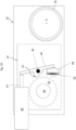
Figure 3 , theoutput rod 26 is at a linear position within thecavity 204 where theoutput rod 26 does not abut against thecam 142. When theoutput rod 26 retracts within thecavity 204, it will eventually come into contact with anangled end 148 of thecam 142. Theangled end 148 may be a curved end, e.g. hemispherical, or may be e.g. chamfered (as shown inFigure 8 ). - The
angled end 148 allows thecam 142 to ride up onto a radiallyouter surface 26a of theoutput rod 26 when, during retraction of theoutput rod 26, anend 26b of theoutput rod 26 first comes into alignment with thecam 142. Theend 26b of theoutput rod 26 may also be chamfered or curved (as shown inFigure 8 ) to allow a smooth motion of pushing thecam 142 out from thecavity 204. With brief reference toFigure 5 , this Figure depicts a cross-section of theEMA 100 where theoutput rod 26 is retracted sufficiently far into thehousing 200 that thecam 142 is pressed away from the first axis X and into theanti-extension device 140. - An intermediate axial position D of the
output rod 26, between the end points A and C, is defined as the point where theend 26b of theoutput rod 26 first bears against theangled end 148 of thecam 142 and has pushed thecam 142 into theanti-extension device 140 sufficiently far so as to cause thepawl 52 to disengage fromratchet wheel 54. When theoutput rod 26 is pressing thecam 142 into theanti-extension device 140, theanti-extension device 140 is disabled. That is, in this cam position, regardless of whether thesolenoid 40 is energized or not, thepawl 52 does not contact theratchet wheel 54 and thus theshaft 56 is free to rotate in either direction. - Intermediate axial position D (where the
end 26b of theoutput rod 26 first meets the cam 142) may be identical to position B (where the spoiler is at 0°), but this is not essential. When axial positions D and B are identical, i.e. at the same axial location along axis X, this means that theanti-extension device 140 is disabled whenever thespoiler 34 is at 0° or higher. In this example, when thespoiler 34 is at angles <0°, theanti-extension device 140 is no longer disabled and the engagement/disengagement of thepawl 52 from theratchet wheel 54 is again under the control of thesolenoid 40. - In other embodiments, intermediate axial position D is offset from position B. For example, the intermediate axial position D may be set at a spoiler angle of +10°. In this example, the
anti-extension device 140 will be disabled whenever thespoiler 34 is at a 10° angle or higher. -
Figure 6 shows the cross-section of theanti-extension device 140 when theoutput rod 26 is at the rod position shown inFigure 5 , i.e. where theoutput rod 26 has pushed thecam 142 in to theanti-extension device 140. Here, thefirst flange 144 has compressed the spring and thesecond flange 146 has pushed the second end of thepivotable rod 44 to the second rod position wherein thepawl 52 does not engage theratchet wheel 54. As may be seen, themovable output 42 of thesolenoid 40 is still in its original position (i.e. thesolenoid 40 is not energized) and themovable output 42 is not presently in abutment with thepivotable rod 44. Thus, when theoutput rod 26 has pushed thecam 142 intoanti-extension device 140, thepawl 52 is disengaged from theratchet wheel 52 regardless of whether or not thesolenoid 40 is energized. That is, theanti-extension device 140 is automatically disabled whenever theoutput rod 26 is pressing thecam 142 into theanti-extension device 140. - When the
output rod 26 extends beyond position D, thecam 142 is biased back into thecavity 204 by the force of thespring 50. At this point, theanti-extension device 140 is again under control of thesolenoid 40. That is, if thesolenoid 40 is now energized, themovable output 42 will push thepivotable rod 44 to the second position, where thepawl 52 is disengaged from theratchet wheel 54. - The skilled reader will appreciate that, when the (end 26b of the)
output rod 26 is anywhere within the linear range between points A and D, thesolenoid 40 determines whether theanti-extension device 140 is engaged or not. When the (end 26b) of theoutput rod 26 is anywhere within the linear range between positions D and C, theanti-extension device 140 is automatically disabled, by virtue of thecam 142 being pushed into theanti-extension device 140 and thereby disengaging thepawl 52 from theratchet wheel 54. -
Figure 8 depicts various alternative shapes for theangled end 148 of thecam 142 and for theend 26b of theoutput rod 26.Figure 8 shows: a chamfered end of theoutput rod 26; a rounded end of theoutput rod 26; and a chamfered end of thecam 142. TheEMA 100 may use any combination of the various end shapes depicted in any of the Figures for thecam 142 and for theoutput rod 26. -
Figure 9 shows anaircraft 33 having thespoiler 34. Theaircraft 33 comprises theairframe 32 and the EMA may be connected to any suitable part of the airframe, such as inside of the wing or on the underside of the wing, near thespoiler 34. - While the foregoing discussion has discussed control of a
spoiler 34, theelectromechanical actuator 100 may be used to control different control surfaces of an aircraft, including flaps, slats, ailerons etc.Reference numerals (known) EMA 10 Motor 12 (known) Anti-extension device 14 Torque limiter 16 Gearbox 18 Housing 20 Screw shaft 22 Nut 24 Output rod 26 Outer surface (of output rod) 26a End (of output rod) 26b Connection end (of output rod) 28 Housing connection end 30 Airframe 32 Aircraft 33 Spoiler 34 Solenoid 40 Movable output (of solenoid) 42 Pivotable rod 44 Pivot point (of pivotable rod) 46 Pusher 48 Spring 50 Pawl (on pivot rod) 52 Ratchet wheel 54 Shaft 56 (new) anti-extension device 140 Cam 142 First flange (of cam) 144 Second flange (of cam) 146 End (of cam) 148 (new) housing 200 Aperture (of new housing) 202 Cavity (in new housing) 204 End of range of motion (fully extended) A Axial position when spoiler at 0° B End of range of motion (fully retracted) C Intermediate axial position D Axis of movement of output rod X Axis of movement of cam Y
Claims (12)
- An electromechanical actuator (100) comprising:a motor (12);a gearbox (18);an anti-extension device (140) mounted between the motor and the gearbox; wherein the motor and anti-extension device are mounted on a housing (200) of the actuator;a screw shaft (22);a nut (24) mounted on the screw shaft;an output rod (26) connected to the nut, the output rod having a linear range of motion defined between full extension of the output rod at a first end point (A) and full retraction of the output rod at a second end point (C);wherein the screw shaft, nut, and output rod are located in a cavity (204) of the housing;wherein the output rod and nut are held against rotation relative to the housing, such that rotation of the screw shaft drives the output rod to move linearly within the housing;wherein the anti-extension device (140) comprises:a ratchet wheel (54) mounted on a shaft (56) arranged to be driven by the motor;a pivotable rod (44) comprising a pawl (52); the pivotable rod being pivotable between a first rod position in which the pawl (52) engages with the ratchet wheel to prevent rotation of the ratchet wheel in one direction of rotation, and a second rod position in which the pawl does not prevent rotation of the ratchet wheel;a cam (142) connected to the pivotable rod, the cam movable between a first cam position and a second cam position, wherein the cam is biased by a spring (50) towards the first cam position in which a portion of the cam extends through an aperture (202) in the housing and into the cavity (204); wherein, in the second cam position, the cam holds the pivotable rod at the second rod position in which the pawl does not prevent rotation of the ratchet wheel;wherein, when an axial end (26b) of the output rod (26) is at a predetermined intermediate point (D) or between the intermediate point (D) and the second end point (C), the cam is moved to the second cam position by an outer surface (26a) of the output rod bearing against the cam; and wherein when the axial end of the output rod is between the intermediate point (D) and the first end point (A), the output rod does not bear against the cam.
- The electromechanical actuator of claim 1, wherein the housing comprises a housing connection end (30) for connecting the actuator to an airframe; and wherein the output rod comprises an output rod connection end (28) for connecting the actuator to a spoiler (34).
- The electromechanical actuator of any preceding claim, wherein the cam has a curved or chamfered end (148); and/or wherein the end (26b) of the output rod is curved or chamfered.
- The electromechanical actuator of any preceding claim, wherein the anti-extension device is directly connected to the gearbox.
- The electromechanical actuator of any preceding claim, wherein the anti-extension device further comprises a solenoid (40) having a movable output (42);
wherein, when the axial end of the output rod is between the intermediate point (D) and the first end point (A), movement of the movable output moves the pivotable rod to the second rod position. - The electromechanical actuator of claim 5, wherein when an axial end (26b) of the output rod (26) is at the predetermined intermediate point (D) or between the intermediate point (D) and the second end point (C), movement of the movable output does not affect the position of the pivotable rod.
- The electromechanical actuator of any preceding claim, wherein the electromechanical actuator does not comprise a torque limiter at any location along a load path between the motor and the screw shaft.
- An aircraft (33) comprising an airframe (32) and a flight surface (34), and the electromechanical actuator (110) of any preceding claim;
wherein the housing (200) of the electromechanical actuator is connected to the airframe and the output rod (26) of the electromechanical actuator is connected to the flight surface, such that the position of the output rod relative to the housing controls an angular position of the flight surface relative to the airframe. - The aircraft of claim 8, wherein the actuator is arranged such that when the end (26b) of the output rod is at a second intermediate axial point (B), the flight surface is at an angle of zero degrees relative to the airframe.
- The aircraft of claim 9, wherein the second intermediate axial point (B) is coincident with the predetermined intermediate point (D), such that the output rod bears against the cam only when the spoiler at an angle of greater than zero degrees relative to the airframe.
- The aircraft of claim 9, wherein the second intermediate point (B) is at a different axial location from the predetermined intermediate point (D); optionally wherein the second intermediate point is located axially between the predetermined intermediate point (D) and the second end point (C).
- The aircraft of claim 11, wherein the flight surface is a spoiler (34).
Priority Applications (3)
| Application Number | Priority Date | Filing Date | Title |
|---|---|---|---|
| EP22306118.5A EP4311768B1 (en) | 2022-07-27 | 2022-07-27 | Spoiler actuator |
| CA3201336A CA3201336A1 (en) | 2022-07-27 | 2023-05-31 | Spoiler actuator |
| US18/348,420 US12384526B2 (en) | 2022-07-27 | 2023-07-07 | Spoiler actuator |
Applications Claiming Priority (1)
| Application Number | Priority Date | Filing Date | Title |
|---|---|---|---|
| EP22306118.5A EP4311768B1 (en) | 2022-07-27 | 2022-07-27 | Spoiler actuator |
Publications (2)
| Publication Number | Publication Date |
|---|---|
| EP4311768A1 true EP4311768A1 (en) | 2024-01-31 |
| EP4311768B1 EP4311768B1 (en) | 2025-04-23 |
Family
ID=82846385
Family Applications (1)
| Application Number | Title | Priority Date | Filing Date |
|---|---|---|---|
| EP22306118.5A Active EP4311768B1 (en) | 2022-07-27 | 2022-07-27 | Spoiler actuator |
Country Status (3)
| Country | Link |
|---|---|
| US (1) | US12384526B2 (en) |
| EP (1) | EP4311768B1 (en) |
| CA (1) | CA3201336A1 (en) |
Citations (2)
| Publication number | Priority date | Publication date | Assignee | Title |
|---|---|---|---|---|
| WO1998042567A1 (en) * | 1997-03-25 | 1998-10-01 | Sundstrand Corporation | Aircraft spoiler blow-down mechanism |
| EP3620334A1 (en) * | 2018-09-05 | 2020-03-11 | WABCO Europe BVBA | Brake actuator for a vehicle, in particular commercial vehicle, and brake system therewith |
Family Cites Families (6)
| Publication number | Priority date | Publication date | Assignee | Title |
|---|---|---|---|---|
| US6116103A (en) * | 1998-05-29 | 2000-09-12 | P. L. Porter Co. | Device for securing gear nut on actuator |
| FR2988797B1 (en) * | 2012-04-02 | 2015-04-24 | Sagem Defense Securite | ELECTROMECHANICAL FLOATING SURFACE ACTUATOR FOR AIRCRAFT AND AIRCRAFT PROVIDED WITH SUCH AN ACTUATOR |
| EP3018384A1 (en) | 2014-11-06 | 2016-05-11 | Goodrich Actuation Systems SAS | Rotary actuator for controlling a flight control surface |
| RU2714658C1 (en) * | 2016-12-30 | 2020-02-18 | Сафран Электроникс Энд Дифенс | Drive with passive locking |
| FR3063532B1 (en) * | 2017-03-06 | 2019-04-05 | Safran Electronics & Defense | ACTUATOR EQUIPPED WITH A NO BACK SYSTEM WITH INHIBITION AREA |
| US11873092B2 (en) * | 2020-12-16 | 2024-01-16 | The Boeing Company | Trim actuators for horizontal stabilizers and methods of controlling horizontal stabilizers |
-
2022
- 2022-07-27 EP EP22306118.5A patent/EP4311768B1/en active Active
-
2023
- 2023-05-31 CA CA3201336A patent/CA3201336A1/en active Pending
- 2023-07-07 US US18/348,420 patent/US12384526B2/en active Active
Patent Citations (2)
| Publication number | Priority date | Publication date | Assignee | Title |
|---|---|---|---|---|
| WO1998042567A1 (en) * | 1997-03-25 | 1998-10-01 | Sundstrand Corporation | Aircraft spoiler blow-down mechanism |
| EP3620334A1 (en) * | 2018-09-05 | 2020-03-11 | WABCO Europe BVBA | Brake actuator for a vehicle, in particular commercial vehicle, and brake system therewith |
Also Published As
| Publication number | Publication date |
|---|---|
| US20240034460A1 (en) | 2024-02-01 |
| EP4311768B1 (en) | 2025-04-23 |
| US12384526B2 (en) | 2025-08-12 |
| CA3201336A1 (en) | 2024-01-27 |
Similar Documents
| Publication | Publication Date | Title |
|---|---|---|
| US10538310B2 (en) | Near synchronous distributed hydraulic motor driven actuation system | |
| US10215246B2 (en) | Integrated torque limiter/no-back device | |
| CN103946590B (en) | Electromechanical actuators for aircraft control surfaces and aircraft provided with such actuators | |
| US9162751B2 (en) | Apparatus for use on an aircraft | |
| US11498658B2 (en) | System for an aircraft wing | |
| CN111452956A (en) | Actuator assembly, wing, aircraft and method for moving a wing tip device | |
| EP3613667B1 (en) | Linear actuator with testable cone no-back and torque limiter | |
| EP4039586B1 (en) | Actuator assembly | |
| US8152098B2 (en) | Torque limiter with brake | |
| EP1980770A2 (en) | Actuator arrangement | |
| EP4311768B1 (en) | Spoiler actuator | |
| US20180080535A1 (en) | Actuator no-back arrangement | |
| US9809326B2 (en) | Method for adjusting the play in a high-lift system of an aircraft | |
| US12525849B2 (en) | EMA droop function and stops protection management | |
| US20230322365A1 (en) | Runaway emergency actuator brake | |
| US7631737B2 (en) | Method and a system for setting into coincidence, a technique, a drive device, and an aircraft | |
| BR102023012614A2 (en) | ELECTROMECHANICAL ACTUATOR, AND, AIRCRAFT | |
| EP4219297B1 (en) | Aerostructure actuation system |
Legal Events
| Date | Code | Title | Description |
|---|---|---|---|
| PUAI | Public reference made under article 153(3) epc to a published international application that has entered the european phase |
Free format text: ORIGINAL CODE: 0009012 |
|
| STAA | Information on the status of an ep patent application or granted ep patent |
Free format text: STATUS: THE APPLICATION HAS BEEN PUBLISHED |
|
| AK | Designated contracting states |
Kind code of ref document: A1 Designated state(s): AL AT BE BG CH CY CZ DE DK EE ES FI FR GB GR HR HU IE IS IT LI LT LU LV MC MK MT NL NO PL PT RO RS SE SI SK SM TR |
|
| STAA | Information on the status of an ep patent application or granted ep patent |
Free format text: STATUS: REQUEST FOR EXAMINATION WAS MADE |
|
| 17P | Request for examination filed |
Effective date: 20240725 |
|
| RBV | Designated contracting states (corrected) |
Designated state(s): AL AT BE BG CH CY CZ DE DK EE ES FI FR GB GR HR HU IE IS IT LI LT LU LV MC MK MT NL NO PL PT RO RS SE SI SK SM TR |
|
| GRAP | Despatch of communication of intention to grant a patent |
Free format text: ORIGINAL CODE: EPIDOSNIGR1 |
|
| STAA | Information on the status of an ep patent application or granted ep patent |
Free format text: STATUS: GRANT OF PATENT IS INTENDED |
|
| RIC1 | Information provided on ipc code assigned before grant |
Ipc: F16H 25/20 20060101ALI20241115BHEP Ipc: F16H 25/24 20060101ALI20241115BHEP Ipc: B64C 13/50 20060101AFI20241115BHEP |
|
| INTG | Intention to grant announced |
Effective date: 20241205 |
|
| GRAS | Grant fee paid |
Free format text: ORIGINAL CODE: EPIDOSNIGR3 |
|
| GRAA | (expected) grant |
Free format text: ORIGINAL CODE: 0009210 |
|
| STAA | Information on the status of an ep patent application or granted ep patent |
Free format text: STATUS: THE PATENT HAS BEEN GRANTED |
|
| AK | Designated contracting states |
Kind code of ref document: B1 Designated state(s): AL AT BE BG CH CY CZ DE DK EE ES FI FR GB GR HR HU IE IS IT LI LT LU LV MC MK MT NL NO PL PT RO RS SE SI SK SM TR |
|
| REG | Reference to a national code |
Ref country code: GB Ref legal event code: FG4D |
|
| REG | Reference to a national code |
Ref country code: CH Ref legal event code: EP |
|
| REG | Reference to a national code |
Ref country code: DE Ref legal event code: R096 Ref document number: 602022013514 Country of ref document: DE |
|
| REG | Reference to a national code |
Ref country code: IE Ref legal event code: FG4D |
|
| PGFP | Annual fee paid to national office [announced via postgrant information from national office to epo] |
Ref country code: FR Payment date: 20250620 Year of fee payment: 4 |
|
| REG | Reference to a national code |
Ref country code: NL Ref legal event code: MP Effective date: 20250423 |
|
| PG25 | Lapsed in a contracting state [announced via postgrant information from national office to epo] |
Ref country code: NL Free format text: LAPSE BECAUSE OF FAILURE TO SUBMIT A TRANSLATION OF THE DESCRIPTION OR TO PAY THE FEE WITHIN THE PRESCRIBED TIME-LIMIT Effective date: 20250423 |
|
| REG | Reference to a national code |
Ref country code: AT Ref legal event code: MK05 Ref document number: 1787551 Country of ref document: AT Kind code of ref document: T Effective date: 20250423 |
|
| PG25 | Lapsed in a contracting state [announced via postgrant information from national office to epo] |
Ref country code: FI Free format text: LAPSE BECAUSE OF FAILURE TO SUBMIT A TRANSLATION OF THE DESCRIPTION OR TO PAY THE FEE WITHIN THE PRESCRIBED TIME-LIMIT Effective date: 20250423 Ref country code: PT Free format text: LAPSE BECAUSE OF FAILURE TO SUBMIT A TRANSLATION OF THE DESCRIPTION OR TO PAY THE FEE WITHIN THE PRESCRIBED TIME-LIMIT Effective date: 20250825 Ref country code: ES Free format text: LAPSE BECAUSE OF FAILURE TO SUBMIT A TRANSLATION OF THE DESCRIPTION OR TO PAY THE FEE WITHIN THE PRESCRIBED TIME-LIMIT Effective date: 20250423 |
|
| PGFP | Annual fee paid to national office [announced via postgrant information from national office to epo] |
Ref country code: DE Payment date: 20250620 Year of fee payment: 4 |
|
| REG | Reference to a national code |
Ref country code: LT Ref legal event code: MG9D |
|
| PG25 | Lapsed in a contracting state [announced via postgrant information from national office to epo] |
Ref country code: NO Free format text: LAPSE BECAUSE OF FAILURE TO SUBMIT A TRANSLATION OF THE DESCRIPTION OR TO PAY THE FEE WITHIN THE PRESCRIBED TIME-LIMIT Effective date: 20250723 Ref country code: GR Free format text: LAPSE BECAUSE OF FAILURE TO SUBMIT A TRANSLATION OF THE DESCRIPTION OR TO PAY THE FEE WITHIN THE PRESCRIBED TIME-LIMIT Effective date: 20250724 |
|
| PG25 | Lapsed in a contracting state [announced via postgrant information from national office to epo] |
Ref country code: PL Free format text: LAPSE BECAUSE OF FAILURE TO SUBMIT A TRANSLATION OF THE DESCRIPTION OR TO PAY THE FEE WITHIN THE PRESCRIBED TIME-LIMIT Effective date: 20250423 |
|
| PGFP | Annual fee paid to national office [announced via postgrant information from national office to epo] |
Ref country code: IT Payment date: 20250731 Year of fee payment: 4 |
|
| PG25 | Lapsed in a contracting state [announced via postgrant information from national office to epo] |
Ref country code: BG Free format text: LAPSE BECAUSE OF FAILURE TO SUBMIT A TRANSLATION OF THE DESCRIPTION OR TO PAY THE FEE WITHIN THE PRESCRIBED TIME-LIMIT Effective date: 20250423 |
|
| PG25 | Lapsed in a contracting state [announced via postgrant information from national office to epo] |
Ref country code: HR Free format text: LAPSE BECAUSE OF FAILURE TO SUBMIT A TRANSLATION OF THE DESCRIPTION OR TO PAY THE FEE WITHIN THE PRESCRIBED TIME-LIMIT Effective date: 20250423 |
|
| PG25 | Lapsed in a contracting state [announced via postgrant information from national office to epo] |
Ref country code: AT Free format text: LAPSE BECAUSE OF FAILURE TO SUBMIT A TRANSLATION OF THE DESCRIPTION OR TO PAY THE FEE WITHIN THE PRESCRIBED TIME-LIMIT Effective date: 20250423 |
|
| PG25 | Lapsed in a contracting state [announced via postgrant information from national office to epo] |
Ref country code: RS Free format text: LAPSE BECAUSE OF FAILURE TO SUBMIT A TRANSLATION OF THE DESCRIPTION OR TO PAY THE FEE WITHIN THE PRESCRIBED TIME-LIMIT Effective date: 20250723 |
|
| PG25 | Lapsed in a contracting state [announced via postgrant information from national office to epo] |
Ref country code: IS Free format text: LAPSE BECAUSE OF FAILURE TO SUBMIT A TRANSLATION OF THE DESCRIPTION OR TO PAY THE FEE WITHIN THE PRESCRIBED TIME-LIMIT Effective date: 20250823 |
|
| PG25 | Lapsed in a contracting state [announced via postgrant information from national office to epo] |
Ref country code: LV Free format text: LAPSE BECAUSE OF FAILURE TO SUBMIT A TRANSLATION OF THE DESCRIPTION OR TO PAY THE FEE WITHIN THE PRESCRIBED TIME-LIMIT Effective date: 20250423 |
|
| PG25 | Lapsed in a contracting state [announced via postgrant information from national office to epo] |
Ref country code: SM Free format text: LAPSE BECAUSE OF FAILURE TO SUBMIT A TRANSLATION OF THE DESCRIPTION OR TO PAY THE FEE WITHIN THE PRESCRIBED TIME-LIMIT Effective date: 20250423 Ref country code: DK Free format text: LAPSE BECAUSE OF FAILURE TO SUBMIT A TRANSLATION OF THE DESCRIPTION OR TO PAY THE FEE WITHIN THE PRESCRIBED TIME-LIMIT Effective date: 20250423 |
|
| PG25 | Lapsed in a contracting state [announced via postgrant information from national office to epo] |
Ref country code: CZ Free format text: LAPSE BECAUSE OF FAILURE TO SUBMIT A TRANSLATION OF THE DESCRIPTION OR TO PAY THE FEE WITHIN THE PRESCRIBED TIME-LIMIT Effective date: 20250423 |
|
| PG25 | Lapsed in a contracting state [announced via postgrant information from national office to epo] |
Ref country code: EE Free format text: LAPSE BECAUSE OF FAILURE TO SUBMIT A TRANSLATION OF THE DESCRIPTION OR TO PAY THE FEE WITHIN THE PRESCRIBED TIME-LIMIT Effective date: 20250423 |
|
| REG | Reference to a national code |
Ref country code: DE Ref legal event code: R097 Ref document number: 602022013514 Country of ref document: DE |
|
| PG25 | Lapsed in a contracting state [announced via postgrant information from national office to epo] |
Ref country code: SK Free format text: LAPSE BECAUSE OF FAILURE TO SUBMIT A TRANSLATION OF THE DESCRIPTION OR TO PAY THE FEE WITHIN THE PRESCRIBED TIME-LIMIT Effective date: 20250423 |
|
| REG | Reference to a national code |
Ref country code: CH Ref legal event code: U11 Free format text: ST27 STATUS EVENT CODE: U-0-0-U10-U11 (AS PROVIDED BY THE NATIONAL OFFICE) Effective date: 20260130 |
|
| PGFP | Annual fee paid to national office [announced via postgrant information from national office to epo] |
Ref country code: LU Payment date: 20260130 Year of fee payment: 4 |
|
| PLBE | No opposition filed within time limit |
Free format text: ORIGINAL CODE: 0009261 |
|
| STAA | Information on the status of an ep patent application or granted ep patent |
Free format text: STATUS: NO OPPOSITION FILED WITHIN TIME LIMIT |
|
| REG | Reference to a national code |
Ref country code: CH Ref legal event code: L10 Free format text: ST27 STATUS EVENT CODE: U-0-0-L10-L00 (AS PROVIDED BY THE NATIONAL OFFICE) Effective date: 20260304 |
|
| PG25 | Lapsed in a contracting state [announced via postgrant information from national office to epo] |
Ref country code: RO Free format text: LAPSE BECAUSE OF FAILURE TO SUBMIT A TRANSLATION OF THE DESCRIPTION OR TO PAY THE FEE WITHIN THE PRESCRIBED TIME-LIMIT Effective date: 20250423 |
|
| 26N | No opposition filed |
Effective date: 20260126 |
|
| PGFP | Annual fee paid to national office [announced via postgrant information from national office to epo] |
Ref country code: IE Payment date: 20260130 Year of fee payment: 4 |
|
| PGFP | Annual fee paid to national office [announced via postgrant information from national office to epo] |
Ref country code: BE Payment date: 20260130 Year of fee payment: 4 |
|
| PGFP | Annual fee paid to national office [announced via postgrant information from national office to epo] |
Ref country code: CH Payment date: 20260130 Year of fee payment: 4 |