EP4311766A1 - Wing for an aircraft - Google Patents
Wing for an aircraft Download PDFInfo
- Publication number
- EP4311766A1 EP4311766A1 EP22187881.2A EP22187881A EP4311766A1 EP 4311766 A1 EP4311766 A1 EP 4311766A1 EP 22187881 A EP22187881 A EP 22187881A EP 4311766 A1 EP4311766 A1 EP 4311766A1
- Authority
- EP
- European Patent Office
- Prior art keywords
- flap
- edge part
- wing
- trailing edge
- leading edge
- Prior art date
- Legal status (The legal status is an assumption and is not a legal conclusion. Google has not performed a legal analysis and makes no representation as to the accuracy of the status listed.)
- Granted
Links
Images

Classifications
-
- B—PERFORMING OPERATIONS; TRANSPORTING
- B64—AIRCRAFT; AVIATION; COSMONAUTICS
- B64C—AEROPLANES; HELICOPTERS
- B64C9/00—Adjustable control surfaces or members, e.g. rudders
- B64C9/14—Adjustable control surfaces or members, e.g. rudders forming slots
- B64C9/16—Adjustable control surfaces or members, e.g. rudders forming slots at the rear of the wing
- B64C9/18—Adjustable control surfaces or members, e.g. rudders forming slots at the rear of the wing by single flaps
-
- B—PERFORMING OPERATIONS; TRANSPORTING
- B64—AIRCRAFT; AVIATION; COSMONAUTICS
- B64C—AEROPLANES; HELICOPTERS
- B64C9/00—Adjustable control surfaces or members, e.g. rudders
- B64C9/02—Mounting or supporting thereof
-
- B—PERFORMING OPERATIONS; TRANSPORTING
- B64—AIRCRAFT; AVIATION; COSMONAUTICS
- B64C—AEROPLANES; HELICOPTERS
- B64C13/00—Control systems or transmitting systems for actuating flying-control surfaces, lift-increasing flaps, air brakes, or spoilers
- B64C13/24—Transmitting means
- B64C13/26—Transmitting means without power amplification or where power amplification is irrelevant
- B64C13/28—Transmitting means without power amplification or where power amplification is irrelevant mechanical
- B64C13/30—Transmitting means without power amplification or where power amplification is irrelevant mechanical using cable, chain, or rod mechanisms
-
- B—PERFORMING OPERATIONS; TRANSPORTING
- B64—AIRCRAFT; AVIATION; COSMONAUTICS
- B64C—AEROPLANES; HELICOPTERS
- B64C3/00—Wings
- B64C3/28—Leading or trailing edges attached to primary structures, e.g. forming fixed slots
-
- B—PERFORMING OPERATIONS; TRANSPORTING
- B64—AIRCRAFT; AVIATION; COSMONAUTICS
- B64C—AEROPLANES; HELICOPTERS
- B64C3/00—Wings
- B64C3/38—Adjustment of complete wings or parts thereof
-
- B—PERFORMING OPERATIONS; TRANSPORTING
- B64—AIRCRAFT; AVIATION; COSMONAUTICS
- B64C—AEROPLANES; HELICOPTERS
- B64C9/00—Adjustable control surfaces or members, e.g. rudders
- B64C9/06—Adjustable control surfaces or members, e.g. rudders with two or more independent movements
-
- B—PERFORMING OPERATIONS; TRANSPORTING
- B64—AIRCRAFT; AVIATION; COSMONAUTICS
- B64C—AEROPLANES; HELICOPTERS
- B64C9/00—Adjustable control surfaces or members, e.g. rudders
- B64C9/14—Adjustable control surfaces or members, e.g. rudders forming slots
- B64C9/16—Adjustable control surfaces or members, e.g. rudders forming slots at the rear of the wing
- B64C9/20—Adjustable control surfaces or members, e.g. rudders forming slots at the rear of the wing by multiple flaps
-
- B—PERFORMING OPERATIONS; TRANSPORTING
- B64—AIRCRAFT; AVIATION; COSMONAUTICS
- B64C—AEROPLANES; HELICOPTERS
- B64C9/00—Adjustable control surfaces or members, e.g. rudders
- B64C9/34—Adjustable control surfaces or members, e.g. rudders collapsing or retracting against or within other surfaces or other members
-
- B—PERFORMING OPERATIONS; TRANSPORTING
- B64—AIRCRAFT; AVIATION; COSMONAUTICS
- B64C—AEROPLANES; HELICOPTERS
- B64C13/00—Control systems or transmitting systems for actuating flying-control surfaces, lift-increasing flaps, air brakes, or spoilers
- B64C13/24—Transmitting means
- B64C13/38—Transmitting means with power amplification
- B64C13/50—Transmitting means with power amplification using electrical energy
Definitions
- the present invention relates to a wing for an aircraft. Further aspects of the invention relate to a trailing edge high lift assembly for such a wing, and to an aircraft comprising such a wing and/or comprising such a trailing edge high lift assembly.
- the wing comprises a main wing and a trailing edge high lift assembly.
- the trailing edge high lift assembly is movably arranged at a trailing edge of the main wing and comprises a flap and a connection assembly.
- the connection assembly movably mounts the flap to the main wing, such that the flap is movable relative to the main wing between a retracted position with a reduced chord length and/or curvature of the wing, and at least one extended position with an extended chord length and/or curvature of the wing.
- the connection assembly comprises an actuator unit, e.g. including a rotary motor or a linear motor, for moving the flap between the retracted position and the at least one extended position.
- the flap comprises a leading edge part, in particular a main flap part, comprising the leading edge of the flap, and a trailing edge part, in particular a tab, comprising the trailing edge of the flap and mounted to the leading edge part, in particular to the trailing edge of the leading edge part, in a manner pivotable about a pivot axis preferably extending in a span direction.
- Similar wings are known in the art.
- Some known wings comprise a trailing edge high lift assembly having a flap that is movable relative to the main wing in a rotational manner, e.g. by the flap being fixedly mounted on a lever that is rotatably mounted to the trailing edge of the main wing and that is driven by a drive strut mounted to a rotating drive arm.
- Other known wings have a trailing edge high lift assembly with a flap that is movable relative to the main wing in a combined linear and rotational manner, e.g. by the flap being rotatably mounted on a carriage running along a linear guide rail while the flap is driven by a drive strut mounted to a rotating drive arm, so that the flap carries out a coupled linear and rotational motion.
- Such trailing edge high lift assemblies are designed to be deployed during take-off and landing of an aircraft to increase lift and reduce minimum air speed by increasing wing area, curvature, and angle of attack, and to be retracted during cruise flight when air speed
- a morphing wing that might adjust wing area, curvature, and angle of attack during the entire flight, e.g. as a "real-time" response to gust or to optimise lift, drag and structural loading during the flight.
- This can be achieved by the two-part flap comprising leading edge part and trailing edge part which can be moved relative to one another as required.
- some known wings For moving the trailing edge part relative to the leading edge part of the flap some known wings employ an additional actuator unit.
- Such an additional actuator unit increases weight and costs of the wing.
- the object of the invention is to provide a wing having a simplified trailing edge high lift assembly that allows to reduce weight and costs of the wing.
- the actuator unit is configured for moving the trailing edge part relative to the leading edge part in a way independent from moving the flap relative to the main wing between the retracted position and the at least one extended position. Additionally or alternatively, the actuator unit is configured for moving the flap relative to the main wing between the retracted position and the at least one extended position in a way independent from moving the trailing edge part relative to the leading edge part. Preferably, the actuator unit is configured for driving the trailing edge part relative to the leading edge part and the flap relative to the main wing between the retracted position and the at least one extended position, independently from one another.
- the actuator unit comprising two independently driven output shafts, one output shaft driving the trailing edge part relative to the leading edge part and another output shaft driving the flap relative to the main wing.
- the actuator unit comprising two independently driven output shafts, one output shaft driving the trailing edge part relative to the leading edge part and another output shaft driving the flap relative to the main wing.
- only one actuator unit preferably only one motor, is required to move both the flap relative to the main wing and the trailing edge part relative to the leading edge part of the flap in an independent manner, thereby largely reducing complexity, weight and costs of the wing.
- connection assembly is configured such that the flap is movable relative to the main wing in a rotational manner, i.e. in a pivoting manner.
- the flap is mounted to the main wing in a manner rotatable about a flap rotation axis.
- the flap rotation axis is located outside the profile of the flap, preferably spaced apart from the flap, e.g. by a flap lever arm.
- the flap lever arm is preferably mounted to the main wing via a rib that projects downwards from the lower side of the main wing and that is mounted to the lever arm rotatably via the flap rotation axis.
- Such a rotationally mounted flap relates to a very simple and reliable connection assembly and trailing edge high lift assembly design.
- flap mountings are also possible, in particular flap mountings allowing combined rotational and translational movement of the flap, such as fowler flap mountings including, e.g., a four-bar linkage or a carriage-track mechanism.
- the actuator unit comprises a motor, preferably a single motor, a first output and a second output.
- the motor might be preferably an electric motor, a hydraulic motor, or a pneumatic motor.
- the motor is configured for driving both the first output and the second output in a manner independent from one another.
- the actuation unit comprises only one motor for driving the first output and the second output.
- an additional back-up motor might be provided for redundancy reasons, that is also capable of driving the first output and the second output in defined situations.
- the first output is formed as a first output shaft rotatable about a first shaft axis.
- the second output is formed as a second output shaft rotatable about a second shaft axis.
- Such rotatable output shafts represent a very efficient and compact output concept.
- the first output and/or the second output might also be formed as a linear output, in particular a linearly movable output rod or a ball-screw.
- a first rotating arm is mounted to the first output shaft, preferably fixedly mounted to the first output shaft, preferably mounted to the first output shaft by its one end, and/or preferably mounted to the first output shaft in a way extending transverse to the first shaft axis.
- a second rotating arm is mounted to the second output shaft, preferably fixedly mounted to the second output shaft, preferably mounted to the second output shaft by its one end, and/or preferably mounted to the second output shaft in a way extending transverse to the second shaft axis.
- Such first and second rotating arms are compact and efficient drive members.
- the first rotating arm is coupled to the trailing edge part of the flap preferably via a first linkage comprising at least one first link.
- the first link is rotatably mounted to the first rotating arm and is rotatably mounted to the trailing edge part, preferably to the lower side of the trailing edge part or to a lever mounted to the trailing edge part, preferably to the lower side of the trailing edge part.
- the actuator unit is mounted to the main wing, preferably fixedly mounted to the main wing, preferably mounted to a rib extending downwards from a lower side of the main wing. In such a way, the actuator unit can be reliably mounted and does not need to be mounted to a moving part.
- the second rotating arm is coupled to the leading edge part of the flap or to a flap lever arm preferably fixedly mounted to the leading edge part of the flap and preferably extending downwards from the lower side of the leading edge part, preferably via a second linkage comprising at least one second link.
- the second link is rotatably mounted to the second rotating arm and is rotatably mounted to the leading edge part, preferably to the lower side of the leading edge part or to a flap lever arm mounted to the lower side of the leading edge part. In such a way, an efficient and reliable linkage is formed.
- the actuator unit is mounted to the leading edge part of the flap preferably fixedly mounted to the leading edge part of the flap, preferably to a flap lever arm extending downwards from a lower side of the leading edge part and/or mounted to the lower side of the leading edge part of the flap.
- the second rotating arm is coupled to the main wing, preferably to a rib extending downwards from a lower side of the main wing, preferably via a second linkage comprising at least one second link.
- the second link is rotatably mounted to the second rotating arm and is rotatably mounted to the main wing, preferably to the lower side of the main wing or to a rib mounted to the main wing, preferably to the lower side of the main wing. In such a way, an efficient and reliable linkage is formed.
- the first output shaft and the second output shaft are arranged in a manner extending from opposite sides of the motor or extending from one common side of the motor in a manner coaxial or parallelly spaced from one another. These are all very compact and efficient positions of the first and second output shafts.
- the first output shaft and the second output shaft are coupled to the motor via a differential gear unit preferably configured to control how the rotational power provided by the motor is distributed between the first and second output shafts.
- a differential gear unit represents a very simple and reliable means to control the transmission of rotational power from the motor to any of the first or second output shafts.
- the differential gear unit comprises a differential gear coupled to the motor, a first selection brake coupled between the differential gear and the first output shaft, and a second selection brake coupled between the differential gear and the second output shaft.
- the differential gear unit further comprises a first gear unit, preferably a reduction gear unit, coupled between the first selection brake and the first output shaft and/or a second gear unit, preferably a reduction gear unit, coupled between the second selection brake and the second output shaft.
- the first selection brake In the first operation mode, the first selection brake is engaged and the second selection brake is released, so that the second output shaft is driven by the motor and the first output shaft is still.
- the second selection brake In the second operation mode, the second selection brake is engaged and the first selection brake is released, so that the first output shaft is driven by the motor and the second output shaft is still. In such a way, a very simple and efficient differential gear unit is formed.
- a further aspect of the present invention relates to a trailing edge high lift assembly for the wing and/or as used in the wing according to any of the embodiments explained above.
- the trailing edge high lift assembly comprises a flap and a connection assembly for movably mounting the flap to the main wing, such that the flap is movable between a retracted position and at least one extended position.
- the connection assembly comprises an actuator unit for moving the flap between the retracted position and the at least one extended position.
- the flap comprises a leading edge part and a trailing edge part mounted to the leading edge part in a manner pivotable about a pivot axis.
- the actuator unit is configured for moving the trailing edge part relative to the leading edge part in a way independent from moving the flap relative to the main wing between the retracted position and the at least one extended position.
- the actuator unit is configured for moving the flap relative to the main wing between the retracted position and the at least one extended position in a way independent from moving the trailing edge part relative to the leading edge part.
- a further aspect of the present invention relates to an aircraft comprising the wing according to any of the embodiments explained above, and/or comprising the trailing edge high lift assembly according to any of the embodiments explained above.
- the features and effects explained above in connection with the wing and the trailing edge high lift assembly apply vis-à-vis also to the aircraft.
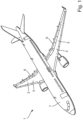
- Fig. 1 shows an exemplary aircraft 1 according to an embodiment of the present invention.
- the aircraft 1 comprises a wing 3 including a main wing 5 mounted to a fuselage 7, and a trailing edge high lift assembly 9 including a flap 11 movably mounted to the main wing 5.
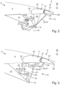
- Figs. 2 and 3 illustrate two embodiments of the wing 3 of the aircraft 1 shown in Fig. 1 .
- the wing 3 according to both first and second embodiments as shown in Figs. 2 and 3 comprises a main wing 5 and a trailing edge high lift assembly 9.
- the trailing edge high lift assembly 9 is movably arranged at a trailing edge of the main wing 5 and comprises a flap 11 and a connection assembly 13.
- the connection assembly 13 movably mounts the flap 11 to the main wing 5, such that the flap 11 is movable between a retracted position with a reduced chord length and curvature of the wing 3, and at least one extended position with an extended chord length and curvature of the wing 3.
- the flap 11 is mounted to the main wing 5 in a manner rotatable about a flap rotation axis 19, wherein the flap rotation axis 19 is located outside the flap profile spaced apart from the flap 11 by a flap lever arm 20.
- the flap lever arm 20 is mounted to the main wing 5 via a rib 21 that projects downwards from the lower side of the main wing 5 and that is mounted to the lever arm 20 rotatably via the flap rotation axis 19.
- the flap 11 comprises a leading edge part 23 including the leading edge 25 of the flap 11, and a trailing edge part 27 including the trailing edge 29 of the flap 11 and mounted to the leading edge part 23 in a manner pivotable about a pivot axis 31 extending in a span direction 33.
- the connection assembly 13 comprises an actuator unit 35 for moving the flap 11 relative to the main wing 5 between the retracted position and the at least one extended position, and for moving the trailing edge part 27 relative to the leading edge part 23.
- the actuator unit 35 is configured for moving the trailing edge part 27 relative to the leading edge part 23 in a way independent from moving the flap 11 relative to the main wing 5 between the retracted position and the at least one extended position.
- the actuator unit 35 is configured for moving the flap 11 relative to the main wing 5 between the retracted position and the at least one extended position in a way independent from moving the trailing edge part 27 relative to the leading edge part 23.
- the actuator unit 35 is configured for driving the trailing edge part 27 relative to the leading edge part 23 and the flap 11 relative to the main wing 5 in a way independently from one another.
- the actuator unit 35 comprises a motor 37, a first output 39 and a second output 41.
- the motor 37 in the present embodiment is an electric motor but might also be e.g. a hydraulic motor or a pneumatic motor.
- the motor 37 is configured for driving both the first output 39 and the second output 41 in a manner independent from one another.
- the first output 39 is formed as a first output shaft 49 rotatable about a first shaft axis 43.
- the second output 41 is formed as a second output shaft 53 rotatable about a second shaft axis 45.
- a first rotating arm 47 is fixedly mounted to the first output shaft 49 by its one end in a way extending transverse to the first shaft axis 43.
- a second rotating arm 51 is fixedly mounted to the second output shaft 53 by its one end in a way extending transverse to the second shaft axis 45.
- the first rotating arm 47 is coupled by its opposite end to the trailing edge part 27 of the flap 11 via a first linkage 55 comprising a first link 57.
- the first link 57 is rotatably mounted to the first rotating arm 47 and in a spaced position is rotatably mounted to a lever 59 mounted to a lower side of the trailing edge part 27.
- the actuator unit 35 is fixedly mounted to a rib 21 of the main wing 5 extending downwards from a lower side of the main wing 5.
- the second rotating arm 51 is coupled by its opposite end to a flap lever arm 20 fixedly mounted to the leading edge part 23 of the flap 11 and extending downwards from the lower side of the leading edge part 23, via a second linkage 63 comprising a second link 65.
- the second link 65 is rotatably mounted to the second rotating arm 51 and is rotatably mounted to the flap lever arm 20 mounted to the lower side of the leading edge part 23.
- the actuator unit 35 is fixedly mounted to a flap lever arm 20 extending downwards from a lower side of the leading edge part 23 of the flap 11.
- the second rotating arm 51 is coupled to a rib 21 extending downwards from a lower side of the main wing 5 via a second linkage 63 comprising a second link 65.
- the second link 65 is rotatably mounted to the second rotating arm 51 and is rotatably mounted to a rib 21 mounted to the lower side of the main wing 5.
- Figs. 4 to 6 three alternative embodiments of the actuator unit 35 of the wings 3 shown in Figs. 2 and 3 are shown having three different arrangements of the first and second output shafts 49, 53.
- the first output shaft 49 and the second output shaft 53 are arranged in a manner extending away from the motor 37 on opposite sides of the motor 37.
- the first output shaft 49 and the second output shaft 53 are arranged in a manner extending away from the motor 37 on one common side of the motor 37 in a coaxial way.
- the first output shaft 49 and the second output shaft 53 are arranged in a manner extending away from the motor 37 on one common side of the motor 37 in a way parallelly spaced from one another.
- the first output shaft 49 and the second output shaft 53 of the wings 3 shown in Figs. 2 and 3 are coupled to the motor 37 via a differential gear unit 67 configured to control how the rotational power provided by the motor 37 is distributed between the first and second output shafts 49, 53.
- the differential gear unit 67 comprises a differential gear 69 coupled to the motor 37, a first selection brake 71 coupled between the differential gear 69 and the first output shaft 49, and a second selection brake 73 coupled between the differential gear 69 and the second output shaft 53.
- the differential gear unit 67 further comprises a first gear unit 75 in the form of a reduction gear unit coupled between the first selection brake 71 and the first output shaft 49 and a second reduction gear unit 77 in the form of a reduction gear unit coupled between the second selection brake 73 and the second output shaft 53.
- the actuator unit 35 can be selectively operated in a first operation mode and in a second operation mode. In the first operation mode shown in Fig. 7 , the first selection brake 71 is engaged and the second selection brake 73 is released, so that the second output shaft 53 is driven by the motor 37 and the first output shaft 49 is still. In the second operation mode shown in Fig. 8 , the second selection brake 73 is engaged and the first selection brake 71 is released, so that the first output shaft 49 is driven by the motor 37 and the second output shaft 53 is still.
- trailing edge high lift assembly 9 By the trailing edge high lift assembly 9 according to the invention, only one actuator unit 35 is required to move both the flap 11 relative to the main wing 5 and the trailing edge part 27 relative to the leading edge part 23 of the flap 11 in an independent manner, thereby largely reducing complexity, weight and costs of the wing 3.
Landscapes
- Engineering & Computer Science (AREA)
- Aviation & Aerospace Engineering (AREA)
- Mechanical Engineering (AREA)
- Automation & Control Theory (AREA)
- Transmission Devices (AREA)
Abstract
Description
- The present invention relates to a wing for an aircraft. Further aspects of the invention relate to a trailing edge high lift assembly for such a wing, and to an aircraft comprising such a wing and/or comprising such a trailing edge high lift assembly.
- The wing comprises a main wing and a trailing edge high lift assembly. The trailing edge high lift assembly is movably arranged at a trailing edge of the main wing and comprises a flap and a connection assembly. The connection assembly movably mounts the flap to the main wing, such that the flap is movable relative to the main wing between a retracted position with a reduced chord length and/or curvature of the wing, and at least one extended position with an extended chord length and/or curvature of the wing. The connection assembly comprises an actuator unit, e.g. including a rotary motor or a linear motor, for moving the flap between the retracted position and the at least one extended position. The flap comprises a leading edge part, in particular a main flap part, comprising the leading edge of the flap, and a trailing edge part, in particular a tab, comprising the trailing edge of the flap and mounted to the leading edge part, in particular to the trailing edge of the leading edge part, in a manner pivotable about a pivot axis preferably extending in a span direction.
- Similar wings are known in the art. Some known wings comprise a trailing edge high lift assembly having a flap that is movable relative to the main wing in a rotational manner, e.g. by the flap being fixedly mounted on a lever that is rotatably mounted to the trailing edge of the main wing and that is driven by a drive strut mounted to a rotating drive arm. Other known wings have a trailing edge high lift assembly with a flap that is movable relative to the main wing in a combined linear and rotational manner, e.g. by the flap being rotatably mounted on a carriage running along a linear guide rail while the flap is driven by a drive strut mounted to a rotating drive arm, so that the flap carries out a coupled linear and rotational motion. Such trailing edge high lift assemblies are designed to be deployed during take-off and landing of an aircraft to increase lift and reduce minimum air speed by increasing wing area, curvature, and angle of attack, and to be retracted during cruise flight when air speed is high to reduce drag.
- More recent investigations have shown that it might be advantageous to have a morphing wing that might adjust wing area, curvature, and angle of attack during the entire flight, e.g. as a "real-time" response to gust or to optimise lift, drag and structural loading during the flight. This can be achieved by the two-part flap comprising leading edge part and trailing edge part which can be moved relative to one another as required.
- For moving the trailing edge part relative to the leading edge part of the flap some known wings employ an additional actuator unit. Such an additional actuator unit, however, increases weight and costs of the wing.
- The object of the invention is to provide a wing having a simplified trailing edge high lift assembly that allows to reduce weight and costs of the wing.
- This object is achieved in that the actuator unit is configured for moving the trailing edge part relative to the leading edge part in a way independent from moving the flap relative to the main wing between the retracted position and the at least one extended position. Additionally or alternatively, the actuator unit is configured for moving the flap relative to the main wing between the retracted position and the at least one extended position in a way independent from moving the trailing edge part relative to the leading edge part. Preferably, the actuator unit is configured for driving the trailing edge part relative to the leading edge part and the flap relative to the main wing between the retracted position and the at least one extended position, independently from one another. This might be realized by the actuator unit comprising two independently driven output shafts, one output shaft driving the trailing edge part relative to the leading edge part and another output shaft driving the flap relative to the main wing. In such a way, only one actuator unit, preferably only one motor, is required to move both the flap relative to the main wing and the trailing edge part relative to the leading edge part of the flap in an independent manner, thereby largely reducing complexity, weight and costs of the wing.
- According to a preferred embodiment, the connection assembly is configured such that the flap is movable relative to the main wing in a rotational manner, i.e. in a pivoting manner. Preferably, the flap is mounted to the main wing in a manner rotatable about a flap rotation axis. Preferably, the flap rotation axis is located outside the profile of the flap, preferably spaced apart from the flap, e.g. by a flap lever arm. The flap lever arm is preferably mounted to the main wing via a rib that projects downwards from the lower side of the main wing and that is mounted to the lever arm rotatably via the flap rotation axis. Such a rotationally mounted flap relates to a very simple and reliable connection assembly and trailing edge high lift assembly design. However, other flap mountings are also possible, in particular flap mountings allowing combined rotational and translational movement of the flap, such as fowler flap mountings including, e.g., a four-bar linkage or a carriage-track mechanism.
- According to a further preferred embodiment, the actuator unit comprises a motor, preferably a single motor, a first output and a second output. The motor might be preferably an electric motor, a hydraulic motor, or a pneumatic motor. The motor is configured for driving both the first output and the second output in a manner independent from one another. Preferably, the actuation unit comprises only one motor for driving the first output and the second output. However, in some embodiments an additional back-up motor might be provided for redundancy reasons, that is also capable of driving the first output and the second output in defined situations. By such a motor driving first and second outputs, independent movement of the trailing edge part relative to the leading edge part and the flap relative to the main wing by a single motor is enabled.
- In particular, it is preferred that the first output is formed as a first output shaft rotatable about a first shaft axis. Additionally or alternatively, the second output is formed as a second output shaft rotatable about a second shaft axis. Such rotatable output shafts represent a very efficient and compact output concept. However, the first output and/or the second output might also be formed as a linear output, in particular a linearly movable output rod or a ball-screw.
- It is further preferred that a first rotating arm is mounted to the first output shaft, preferably fixedly mounted to the first output shaft, preferably mounted to the first output shaft by its one end, and/or preferably mounted to the first output shaft in a way extending transverse to the first shaft axis. Additionally or alternatively, a second rotating arm is mounted to the second output shaft, preferably fixedly mounted to the second output shaft, preferably mounted to the second output shaft by its one end, and/or preferably mounted to the second output shaft in a way extending transverse to the second shaft axis. Such first and second rotating arms are compact and efficient drive members.
- It is also preferred that the first rotating arm is coupled to the trailing edge part of the flap preferably via a first linkage comprising at least one first link. Preferably, the first link is rotatably mounted to the first rotating arm and is rotatably mounted to the trailing edge part, preferably to the lower side of the trailing edge part or to a lever mounted to the trailing edge part, preferably to the lower side of the trailing edge part. By such a first linkage a simple and efficient coupling can be realized between the first rotating arm and the trailing edge part of the flap.
- According to a preferred embodiment, the actuator unit is mounted to the main wing, preferably fixedly mounted to the main wing, preferably mounted to a rib extending downwards from a lower side of the main wing. In such a way, the actuator unit can be reliably mounted and does not need to be mounted to a moving part.
- In particular, it is preferred that the second rotating arm is coupled to the leading edge part of the flap or to a flap lever arm preferably fixedly mounted to the leading edge part of the flap and preferably extending downwards from the lower side of the leading edge part, preferably via a second linkage comprising at least one second link. Preferably, the second link is rotatably mounted to the second rotating arm and is rotatably mounted to the leading edge part, preferably to the lower side of the leading edge part or to a flap lever arm mounted to the lower side of the leading edge part. In such a way, an efficient and reliable linkage is formed.
- According to an alternative preferred embodiment, the actuator unit is mounted to the leading edge part of the flap preferably fixedly mounted to the leading edge part of the flap, preferably to a flap lever arm extending downwards from a lower side of the leading edge part and/or mounted to the lower side of the leading edge part of the flap. In such a way, movement of the flap relative to the main wing and movement of the trailing edge part relative to the leading edge part are fully decoupled from one another, in particular the flap can be moved relative to the main wing without influencing movement of the trailing edge part relative to the leading edge part.
- In particular, it is preferred that the second rotating arm is coupled to the main wing, preferably to a rib extending downwards from a lower side of the main wing, preferably via a second linkage comprising at least one second link. Preferably, the second link is rotatably mounted to the second rotating arm and is rotatably mounted to the main wing, preferably to the lower side of the main wing or to a rib mounted to the main wing, preferably to the lower side of the main wing. In such a way, an efficient and reliable linkage is formed.
- According to a preferred embodiment, the first output shaft and the second output shaft are arranged in a manner extending from opposite sides of the motor or extending from one common side of the motor in a manner coaxial or parallelly spaced from one another. These are all very compact and efficient positions of the first and second output shafts.
- According to a preferred embodiment, the first output shaft and the second output shaft are coupled to the motor via a differential gear unit preferably configured to control how the rotational power provided by the motor is distributed between the first and second output shafts. Such a differential gear unit represents a very simple and reliable means to control the transmission of rotational power from the motor to any of the first or second output shafts.
- In particular, it is preferred that the differential gear unit comprises a differential gear coupled to the motor, a first selection brake coupled between the differential gear and the first output shaft, and a second selection brake coupled between the differential gear and the second output shaft. Preferably, the differential gear unit further comprises a first gear unit, preferably a reduction gear unit, coupled between the first selection brake and the first output shaft and/or a second gear unit, preferably a reduction gear unit, coupled between the second selection brake and the second output shaft. By selective application of the first and second selective brakes it can be controlled which of the first and second output shafts is provided with rotational power from the motor. Specifically, the actuator unit can be selectively operated in a first operation mode and in a second operation mode. In the first operation mode, the first selection brake is engaged and the second selection brake is released, so that the second output shaft is driven by the motor and the first output shaft is still. In the second operation mode, the second selection brake is engaged and the first selection brake is released, so that the first output shaft is driven by the motor and the second output shaft is still. In such a way, a very simple and efficient differential gear unit is formed.
- A further aspect of the present invention relates to a trailing edge high lift assembly for the wing and/or as used in the wing according to any of the embodiments explained above. In particular, the trailing edge high lift assembly comprises a flap and a connection assembly for movably mounting the flap to the main wing, such that the flap is movable between a retracted position and at least one extended position. The connection assembly comprises an actuator unit for moving the flap between the retracted position and the at least one extended position. The flap comprises a leading edge part and a trailing edge part mounted to the leading edge part in a manner pivotable about a pivot axis. The actuator unit is configured for moving the trailing edge part relative to the leading edge part in a way independent from moving the flap relative to the main wing between the retracted position and the at least one extended position.
- Additionally or alternatively, the actuator unit is configured for moving the flap relative to the main wing between the retracted position and the at least one extended position in a way independent from moving the trailing edge part relative to the leading edge part. The features and effects explained above in connection with the wing apply vis-à-vis also to the trailing edge high lift assembly.
- A further aspect of the present invention relates to an aircraft comprising the wing according to any of the embodiments explained above, and/or comprising the trailing edge high lift assembly according to any of the embodiments explained above. The features and effects explained above in connection with the wing and the trailing edge high lift assembly apply vis-à-vis also to the aircraft.
- Hereinafter, preferred embodiments of the present invention are described in more detail by means of a drawing. The drawing shows in
- Fig. 1
- a perspective view of an aircraft according to an embodiment of the invention,
- Fig. 2
- a schematic cross sectional view across the span direction of a wing according to a first embodiment of the invention with a focus on the trailing edge high lift assembly including the flap,
- Fig. 3
- a schematic cross sectional view across the span direction of a wing according to a second embodiment of the invention with a focus on the trailing edge high lift assembly including the flap,
- Fig. 4
- a schematic top view of a first embodiment of an actuator unit to be used in the wing according to the invention,
- Fig. 5
- a schematic top view of a second embodiment of an actuator unit to be used in the wing according to the invention,
- Fig. 6
- a schematic top view of a third embodiment of an actuator unit to be used in the wing according to the invention,
- Fig. 7
- a function diagram of the actuator unit of the wing according to the invention, in a first operation mode, and
- Fig. 8
- a function diagram of the actuator unit of the wing according to the invention, in a second operation mode.
-
Fig. 1 shows an exemplary aircraft 1 according to an embodiment of the present invention. The aircraft 1 comprises awing 3 including amain wing 5 mounted to afuselage 7, and a trailing edgehigh lift assembly 9 including aflap 11 movably mounted to themain wing 5. -
Figs. 2 and 3 illustrate two embodiments of thewing 3 of the aircraft 1 shown inFig. 1 . Thewing 3 according to both first and second embodiments as shown inFigs. 2 and 3 comprises amain wing 5 and a trailing edgehigh lift assembly 9. The trailing edgehigh lift assembly 9 is movably arranged at a trailing edge of themain wing 5 and comprises aflap 11 and aconnection assembly 13. Theconnection assembly 13 movably mounts theflap 11 to themain wing 5, such that theflap 11 is movable between a retracted position with a reduced chord length and curvature of thewing 3, and at least one extended position with an extended chord length and curvature of thewing 3. Theflap 11 is mounted to themain wing 5 in a manner rotatable about aflap rotation axis 19, wherein theflap rotation axis 19 is located outside the flap profile spaced apart from theflap 11 by aflap lever arm 20. Theflap lever arm 20 is mounted to themain wing 5 via arib 21 that projects downwards from the lower side of themain wing 5 and that is mounted to thelever arm 20 rotatably via theflap rotation axis 19. Theflap 11 comprises aleading edge part 23 including the leadingedge 25 of theflap 11, and a trailingedge part 27 including the trailingedge 29 of theflap 11 and mounted to theleading edge part 23 in a manner pivotable about apivot axis 31 extending in aspan direction 33. - The
connection assembly 13 comprises anactuator unit 35 for moving theflap 11 relative to themain wing 5 between the retracted position and the at least one extended position, and for moving the trailingedge part 27 relative to theleading edge part 23. Specifically, theactuator unit 35 is configured for moving the trailingedge part 27 relative to theleading edge part 23 in a way independent from moving theflap 11 relative to themain wing 5 between the retracted position and the at least one extended position. Additionally or alternatively, theactuator unit 35 is configured for moving theflap 11 relative to themain wing 5 between the retracted position and the at least one extended position in a way independent from moving the trailingedge part 27 relative to theleading edge part 23. Specifically, theactuator unit 35 is configured for driving the trailingedge part 27 relative to theleading edge part 23 and theflap 11 relative to themain wing 5 in a way independently from one another. - In the embodiments shown in
Figs. 2 and 3 , theactuator unit 35 comprises amotor 37, a first output 39 and a second output 41. Themotor 37 in the present embodiment is an electric motor but might also be e.g. a hydraulic motor or a pneumatic motor. Themotor 37 is configured for driving both the first output 39 and the second output 41 in a manner independent from one another. The first output 39 is formed as afirst output shaft 49 rotatable about afirst shaft axis 43. The second output 41 is formed as asecond output shaft 53 rotatable about asecond shaft axis 45. A firstrotating arm 47 is fixedly mounted to thefirst output shaft 49 by its one end in a way extending transverse to thefirst shaft axis 43. A secondrotating arm 51 is fixedly mounted to thesecond output shaft 53 by its one end in a way extending transverse to thesecond shaft axis 45. The firstrotating arm 47 is coupled by its opposite end to the trailingedge part 27 of theflap 11 via a first linkage 55 comprising a first link 57. The first link 57 is rotatably mounted to the firstrotating arm 47 and in a spaced position is rotatably mounted to alever 59 mounted to a lower side of the trailingedge part 27. - In the embodiment shown in
Fig. 2 , theactuator unit 35 is fixedly mounted to arib 21 of themain wing 5 extending downwards from a lower side of themain wing 5. The secondrotating arm 51 is coupled by its opposite end to aflap lever arm 20 fixedly mounted to theleading edge part 23 of theflap 11 and extending downwards from the lower side of theleading edge part 23, via a second linkage 63 comprising a second link 65. The second link 65 is rotatably mounted to the secondrotating arm 51 and is rotatably mounted to theflap lever arm 20 mounted to the lower side of theleading edge part 23. - In the alternative embodiment shown in
Fig. 3 , theactuator unit 35 is fixedly mounted to aflap lever arm 20 extending downwards from a lower side of theleading edge part 23 of theflap 11. The secondrotating arm 51 is coupled to arib 21 extending downwards from a lower side of themain wing 5 via a second linkage 63 comprising a second link 65. The second link 65 is rotatably mounted to the secondrotating arm 51 and is rotatably mounted to arib 21 mounted to the lower side of themain wing 5. - In
Figs. 4 to 6 three alternative embodiments of theactuator unit 35 of thewings 3 shown inFigs. 2 and 3 are shown having three different arrangements of the first andsecond output shafts Fig. 4 , thefirst output shaft 49 and thesecond output shaft 53 are arranged in a manner extending away from themotor 37 on opposite sides of themotor 37. In the embodiment shown inFig. 5 , thefirst output shaft 49 and thesecond output shaft 53 are arranged in a manner extending away from themotor 37 on one common side of themotor 37 in a coaxial way. In the embodiment shown inFig. 6 , thefirst output shaft 49 and thesecond output shaft 53 are arranged in a manner extending away from themotor 37 on one common side of themotor 37 in a way parallelly spaced from one another. - As shown in
Figs. 7 and 8 , thefirst output shaft 49 and thesecond output shaft 53 of thewings 3 shown inFigs. 2 and 3 are coupled to themotor 37 via adifferential gear unit 67 configured to control how the rotational power provided by themotor 37 is distributed between the first andsecond output shafts differential gear unit 67 comprises adifferential gear 69 coupled to themotor 37, afirst selection brake 71 coupled between thedifferential gear 69 and thefirst output shaft 49, and asecond selection brake 73 coupled between thedifferential gear 69 and thesecond output shaft 53. Thedifferential gear unit 67 further comprises afirst gear unit 75 in the form of a reduction gear unit coupled between thefirst selection brake 71 and thefirst output shaft 49 and a secondreduction gear unit 77 in the form of a reduction gear unit coupled between thesecond selection brake 73 and thesecond output shaft 53. By selective application of the first andsecond selection brakes second output shafts motor 37. Specifically, theactuator unit 35 can be selectively operated in a first operation mode and in a second operation mode. In the first operation mode shown inFig. 7 , thefirst selection brake 71 is engaged and thesecond selection brake 73 is released, so that thesecond output shaft 53 is driven by themotor 37 and thefirst output shaft 49 is still. In the second operation mode shown inFig. 8 , thesecond selection brake 73 is engaged and thefirst selection brake 71 is released, so that thefirst output shaft 49 is driven by themotor 37 and thesecond output shaft 53 is still. - By the trailing edge
high lift assembly 9 according to the invention, only oneactuator unit 35 is required to move both theflap 11 relative to themain wing 5 and the trailingedge part 27 relative to theleading edge part 23 of theflap 11 in an independent manner, thereby largely reducing complexity, weight and costs of thewing 3.
Claims (15)
- A wing (3) for an aircraft (1), comprisinga main wing (5) anda trailing edge high lift assembly (9) movably arranged at a trailing edge of the main wing (5), the trailing edge high lift assembly (9) comprisinga flap (11) anda connection assembly (13) movably mounting the flap (11) to the main wing (5), such that the flap (11) is movable between a retracted position and at least one extended position,wherein the connection assembly (13) comprises an actuator unit (35) for moving the flap (11) between the retracted position and the at least one extended position,wherein the flap (11) comprises a leading edge part (23) and a trailing edge part (27) mounted to the leading edge part (23) in a manner pivotable about a pivot axis (31),characterized in thatthe actuator unit (35) is configured for moving the trailing edge part (27) relative to the leading edge part (23) in a way independent from moving the flap (11) between the retracted position and the at least one extended position, and/orthe actuator unit (35) is configured for moving the flap (11) between the retracted position and the at least one extended position in a way independent from moving the trailing edge part (27) relative to the leading edge part (23).
- The wing (3) according to claim 1, wherein the connection assembly (13) is configured such that the flap (11) is movable relative to the main wing (5) in a rotational manner.
- The wing (3) according to claim 1 or 2, wherein the actuator unit (35) comprises a motor (37), a first output (39) and a second output (41), wherein the motor (37) is configured to drive both the first output (39) and the second output (41) in a manner independent from one another.
- The wing (3) according to claim 3, wherein the first output (39) is formed as a first output shaft (49) rotatable about a first shaft axis (43), and/or
wherein the second output (41) is formed as a second output shaft (53) rotatable about a second shaft axis (45). - The wing (3) according to claim 4, wherein a first rotating arm (47) is mounted to the first output shaft (49), and/or
wherein a second rotating arm (51) is mounted to the second output shaft (53). - The wing (3) according to claim 5, wherein the first rotating arm (47) is coupled to the trailing edge part (27) of the flap (11) via a first linkage (55) comprising at least one first link (57).
- The wing (3) according to any of claims 1 to 6, wherein the actuator unit (35) is mounted to the main wing (5).
- The wing (3) according to claim 7 when dependent from claim 6, wherein the second rotating arm (51) is coupled to the leading edge part (23) of the flap (11) or to a flap lever arm (20) mounted to the leading edge part (23) of the flap (11), via a second linkage (63) comprising at least one second link (65).
- The wing (3) according to any of claims 1 to 6, wherein the actuator unit (35) is mounted to the leading edge part (23) of the flap (11) or to a flap lever arm (20) mounted to the leading edge part (23) of the flap (11).
- The wing (3) according to claim 10 when dependent from claim 6, wherein the second rotating arm (51) is coupled to the main wing (5) via a second linkage (63) comprising at least one second link (65).
- The wing (3) according to any of claims 4 to 10, wherein the first output shaft (49) and the second output shaft (53) are arranged in a manner extending from opposite sides of the motor (37) or extending from one common side of the motor (37) in a manner coaxial or parallelly spaced from one another.
- The wing (3) according to any of claims 4 to 11, wherein the first output shaft (49) and the second output shaft (53) are coupled to the motor (37) via a differential gear unit (67).
- The wing (3) according to claim 12, wherein the differential gear unit (67) comprises a differential gear (69) coupled to the motor (37), a first selection brake (71) coupled between the differential gear (69) and the first output shaft (49), and a second selection brake (73) coupled between the differential gear (69) and the second output shaft (53).
- A trailing edge high lift assembly (9) for the wing (3) according to any of claims 1 to 13, comprisinga flap (11) anda connection assembly (13) for movably mounting the flap (11) to the main wing (5), such that the flap (11) is movable between a retracted position and at least one extended position,wherein the connection assembly (13) comprises an actuator unit (35) for moving the flap (11) between the retracted position and the at least one extended position, andwherein the flap (11) comprises a leading edge part (23) and a trailing edge part (27) mounted to the leading edge part (23) in a manner pivotable about a pivot axis (31),characterized in thatthe actuator unit (35) is configured for moving the trailing edge part (27) relative to the leading edge part (23) in a way independent from moving the flap (11) between the retracted position and the at least one extended position, and/orthe actuator unit (35) is configured for moving the flap (11) between the retracted position and the at least one extended position in a way independent from moving the trailing edge part (27) relative to the leading edge part (23).
- An aircraft (1) comprising the wing (3) according to any of claims 1 to 13, and/or comprising the trailing edge high lift assembly (9) according to claim 14.
Priority Applications (3)
| Application Number | Priority Date | Filing Date | Title |
|---|---|---|---|
| EP22187881.2A EP4311766B1 (en) | 2022-07-29 | 2022-07-29 | Wing for an aircraft |
| CN202310944977.8A CN117465658A (en) | 2022-07-29 | 2023-07-28 | Wings, trailing edge high-lift components and aircraft for aircraft |
| US18/361,544 US12208896B2 (en) | 2022-07-29 | 2023-07-28 | Wing for an aircraft |
Applications Claiming Priority (1)
| Application Number | Priority Date | Filing Date | Title |
|---|---|---|---|
| EP22187881.2A EP4311766B1 (en) | 2022-07-29 | 2022-07-29 | Wing for an aircraft |
Publications (2)
| Publication Number | Publication Date |
|---|---|
| EP4311766A1 true EP4311766A1 (en) | 2024-01-31 |
| EP4311766B1 EP4311766B1 (en) | 2025-09-03 |
Family
ID=82786246
Family Applications (1)
| Application Number | Title | Priority Date | Filing Date |
|---|---|---|---|
| EP22187881.2A Active EP4311766B1 (en) | 2022-07-29 | 2022-07-29 | Wing for an aircraft |
Country Status (3)
| Country | Link |
|---|---|
| US (1) | US12208896B2 (en) |
| EP (1) | EP4311766B1 (en) |
| CN (1) | CN117465658A (en) |
Cited By (1)
| Publication number | Priority date | Publication date | Assignee | Title |
|---|---|---|---|---|
| CN119348808A (en) * | 2024-12-05 | 2025-01-24 | 中国航空工业集团公司西安飞机设计研究所 | A slat cover movement mechanism |
Families Citing this family (1)
| Publication number | Priority date | Publication date | Assignee | Title |
|---|---|---|---|---|
| WO2025199474A1 (en) * | 2024-03-22 | 2025-09-25 | Odys Aviation, Inc. | Flap drive mechanism |
Citations (5)
| Publication number | Priority date | Publication date | Assignee | Title |
|---|---|---|---|---|
| DE692059C (en) * | 1937-10-03 | 1940-06-11 | Arado Flugzeugwerke G M B H | Aircraft wing |
| US2379274A (en) * | 1940-08-26 | 1945-06-26 | Ryan Aeronautical Company | Lateral control device for aircraft |
| US4702442A (en) * | 1984-12-06 | 1987-10-27 | The Boeing Company | Aircraft trailing edge flap apparatus |
| US4796840A (en) * | 1986-07-22 | 1989-01-10 | Dornier Gmbh | Trailing edge flap operation in wings |
| US20220227480A1 (en) * | 2021-01-21 | 2022-07-21 | The Boeing Company | Linkage assemblies for moving tabs on control surfaces of aircraft |
Family Cites Families (3)
| Publication number | Priority date | Publication date | Assignee | Title |
|---|---|---|---|---|
| DE2125971C3 (en) * | 1971-05-26 | 1978-08-03 | Vereinigte Flugtechnische Werkefokker Gmbh, 2800 Bremen | Flap arrangement for an aircraft wing |
| US11505304B2 (en) * | 2019-10-18 | 2022-11-22 | The Boeing Company | Aircraft spoiler actuation systems and related methods |
| EP4253228A1 (en) * | 2022-03-31 | 2023-10-04 | Airbus Operations GmbH | Wing for an aircraft |
-
2022
- 2022-07-29 EP EP22187881.2A patent/EP4311766B1/en active Active
-
2023
- 2023-07-28 US US18/361,544 patent/US12208896B2/en active Active
- 2023-07-28 CN CN202310944977.8A patent/CN117465658A/en active Pending
Patent Citations (5)
| Publication number | Priority date | Publication date | Assignee | Title |
|---|---|---|---|---|
| DE692059C (en) * | 1937-10-03 | 1940-06-11 | Arado Flugzeugwerke G M B H | Aircraft wing |
| US2379274A (en) * | 1940-08-26 | 1945-06-26 | Ryan Aeronautical Company | Lateral control device for aircraft |
| US4702442A (en) * | 1984-12-06 | 1987-10-27 | The Boeing Company | Aircraft trailing edge flap apparatus |
| US4796840A (en) * | 1986-07-22 | 1989-01-10 | Dornier Gmbh | Trailing edge flap operation in wings |
| US20220227480A1 (en) * | 2021-01-21 | 2022-07-21 | The Boeing Company | Linkage assemblies for moving tabs on control surfaces of aircraft |
Cited By (1)
| Publication number | Priority date | Publication date | Assignee | Title |
|---|---|---|---|---|
| CN119348808A (en) * | 2024-12-05 | 2025-01-24 | 中国航空工业集团公司西安飞机设计研究所 | A slat cover movement mechanism |
Also Published As
| Publication number | Publication date |
|---|---|
| EP4311766B1 (en) | 2025-09-03 |
| CN117465658A (en) | 2024-01-30 |
| US20240034458A1 (en) | 2024-02-01 |
| US12208896B2 (en) | 2025-01-28 |
Similar Documents
| Publication | Publication Date | Title |
|---|---|---|
| US10899431B2 (en) | System for driving and guiding of a multifunctional trailing edge control surface on an aircraft | |
| US4399970A (en) | Wing leading edge slat | |
| US4995575A (en) | Wing trailing edge flap mechanism | |
| US8517314B2 (en) | Actuator arrangement | |
| EP1316501B1 (en) | Aerodynamic control surface system | |
| RU2464202C2 (en) | Aerofil section leading edge | |
| EP0239138B1 (en) | Aircraft wings with aileron-supported ground speed spoilers and trailing edge flaps | |
| CN104039647B (en) | Wing with main wing and booster body and method for adjusting movement of booster body relative to main wing | |
| US12208896B2 (en) | Wing for an aircraft | |
| US20070176051A1 (en) | Actuation device positioning systems and associated methods, including aircraft spoiler droop systems | |
| EP3461738B1 (en) | High-fowler flap actuation apparatus and related methods | |
| JP2009545478A (en) | High lift system for aircraft | |
| US20210114714A1 (en) | Aircraft spoiler actuation systems and related methods | |
| EP2886451A1 (en) | Trailing-edge flap system for a wing of an aircraft and aircraft comprising a wing and at least one such trailing-edge flap system | |
| US20230271696A1 (en) | Wing for an aircraft | |
| EP3560821B1 (en) | A control surface actuation mechanism | |
| US12208895B2 (en) | Wing for an aircraft | |
| US20240101246A1 (en) | Wing for an aircraft | |
| EP3962810B1 (en) | Actuator arrangement for a fixed leading edge member of an aircraft, wing assembly and aircraft equipped with said actuator arrangement | |
| US12312084B2 (en) | Wing for an aircraft having a flap with a speed brake panel mounted in a rotatable manner | |
| GB2138756A (en) | Wing leading edge slat | |
| JPS6325999B2 (en) | ||
| US12612152B2 (en) | Wing for an aircraft | |
| EP4660074A1 (en) | Wing for an aircraft |
Legal Events
| Date | Code | Title | Description |
|---|---|---|---|
| PUAI | Public reference made under article 153(3) epc to a published international application that has entered the european phase |
Free format text: ORIGINAL CODE: 0009012 |
|
| STAA | Information on the status of an ep patent application or granted ep patent |
Free format text: STATUS: THE APPLICATION HAS BEEN PUBLISHED |
|
| AK | Designated contracting states |
Kind code of ref document: A1 Designated state(s): AL AT BE BG CH CY CZ DE DK EE ES FI FR GB GR HR HU IE IS IT LI LT LU LV MC MK MT NL NO PL PT RO RS SE SI SK SM TR |
|
| STAA | Information on the status of an ep patent application or granted ep patent |
Free format text: STATUS: REQUEST FOR EXAMINATION WAS MADE |
|
| 17P | Request for examination filed |
Effective date: 20240731 |
|
| RBV | Designated contracting states (corrected) |
Designated state(s): AL AT BE BG CH CY CZ DE DK EE ES FI FR GB GR HR HU IE IS IT LI LT LU LV MC MK MT NL NO PL PT RO RS SE SI SK SM TR |
|
| RIC1 | Information provided on ipc code assigned before grant |
Ipc: B64C 13/50 20060101ALN20250416BHEP Ipc: B64C 13/30 20060101ALI20250416BHEP Ipc: B64C 9/20 20060101ALI20250416BHEP Ipc: B64C 9/06 20060101ALI20250416BHEP Ipc: B64C 9/02 20060101AFI20250416BHEP |
|
| GRAP | Despatch of communication of intention to grant a patent |
Free format text: ORIGINAL CODE: EPIDOSNIGR1 |
|
| STAA | Information on the status of an ep patent application or granted ep patent |
Free format text: STATUS: GRANT OF PATENT IS INTENDED |
|
| INTG | Intention to grant announced |
Effective date: 20250527 |
|
| GRAS | Grant fee paid |
Free format text: ORIGINAL CODE: EPIDOSNIGR3 |
|
| GRAA | (expected) grant |
Free format text: ORIGINAL CODE: 0009210 |
|
| STAA | Information on the status of an ep patent application or granted ep patent |
Free format text: STATUS: THE PATENT HAS BEEN GRANTED |
|
| AK | Designated contracting states |
Kind code of ref document: B1 Designated state(s): AL AT BE BG CH CY CZ DE DK EE ES FI FR GB GR HR HU IE IS IT LI LT LU LV MC MK MT NL NO PL PT RO RS SE SI SK SM TR |
|
| REG | Reference to a national code |
Ref country code: CH Ref legal event code: EP |
|
| REG | Reference to a national code |
Ref country code: DE Ref legal event code: R096 Ref document number: 602022020623 Country of ref document: DE |
|
| REG | Reference to a national code |
Ref country code: IE Ref legal event code: FG4D |
|
| REG | Reference to a national code |
Ref country code: NL Ref legal event code: MP Effective date: 20250903 |
|
| PG25 | Lapsed in a contracting state [announced via postgrant information from national office to epo] |
Ref country code: NO Free format text: LAPSE BECAUSE OF FAILURE TO SUBMIT A TRANSLATION OF THE DESCRIPTION OR TO PAY THE FEE WITHIN THE PRESCRIBED TIME-LIMIT Effective date: 20251203 |
|
| REG | Reference to a national code |
Ref country code: LT Ref legal event code: MG9D |
|
| PG25 | Lapsed in a contracting state [announced via postgrant information from national office to epo] |
Ref country code: FI Free format text: LAPSE BECAUSE OF FAILURE TO SUBMIT A TRANSLATION OF THE DESCRIPTION OR TO PAY THE FEE WITHIN THE PRESCRIBED TIME-LIMIT Effective date: 20250903 |
|
| PG25 | Lapsed in a contracting state [announced via postgrant information from national office to epo] |
Ref country code: HR Free format text: LAPSE BECAUSE OF FAILURE TO SUBMIT A TRANSLATION OF THE DESCRIPTION OR TO PAY THE FEE WITHIN THE PRESCRIBED TIME-LIMIT Effective date: 20250903 |
|
| PG25 | Lapsed in a contracting state [announced via postgrant information from national office to epo] |
Ref country code: GR Free format text: LAPSE BECAUSE OF FAILURE TO SUBMIT A TRANSLATION OF THE DESCRIPTION OR TO PAY THE FEE WITHIN THE PRESCRIBED TIME-LIMIT Effective date: 20251204 |
|
| PG25 | Lapsed in a contracting state [announced via postgrant information from national office to epo] |
Ref country code: SE Free format text: LAPSE BECAUSE OF FAILURE TO SUBMIT A TRANSLATION OF THE DESCRIPTION OR TO PAY THE FEE WITHIN THE PRESCRIBED TIME-LIMIT Effective date: 20250903 |
|
| PG25 | Lapsed in a contracting state [announced via postgrant information from national office to epo] |
Ref country code: LV Free format text: LAPSE BECAUSE OF FAILURE TO SUBMIT A TRANSLATION OF THE DESCRIPTION OR TO PAY THE FEE WITHIN THE PRESCRIBED TIME-LIMIT Effective date: 20250903 |
|
| PG25 | Lapsed in a contracting state [announced via postgrant information from national office to epo] |
Ref country code: PL Free format text: LAPSE BECAUSE OF FAILURE TO SUBMIT A TRANSLATION OF THE DESCRIPTION OR TO PAY THE FEE WITHIN THE PRESCRIBED TIME-LIMIT Effective date: 20250903 Ref country code: BG Free format text: LAPSE BECAUSE OF FAILURE TO SUBMIT A TRANSLATION OF THE DESCRIPTION OR TO PAY THE FEE WITHIN THE PRESCRIBED TIME-LIMIT Effective date: 20250903 |
|
| PG25 | Lapsed in a contracting state [announced via postgrant information from national office to epo] |
Ref country code: RS Free format text: LAPSE BECAUSE OF FAILURE TO SUBMIT A TRANSLATION OF THE DESCRIPTION OR TO PAY THE FEE WITHIN THE PRESCRIBED TIME-LIMIT Effective date: 20251203 |
|
| PG25 | Lapsed in a contracting state [announced via postgrant information from national office to epo] |
Ref country code: ES Free format text: LAPSE BECAUSE OF FAILURE TO SUBMIT A TRANSLATION OF THE DESCRIPTION OR TO PAY THE FEE WITHIN THE PRESCRIBED TIME-LIMIT Effective date: 20250903 |
|
| REG | Reference to a national code |
Ref country code: AT Ref legal event code: MK05 Ref document number: 1832760 Country of ref document: AT Kind code of ref document: T Effective date: 20250903 |
|
| PG25 | Lapsed in a contracting state [announced via postgrant information from national office to epo] |
Ref country code: NL Free format text: LAPSE BECAUSE OF FAILURE TO SUBMIT A TRANSLATION OF THE DESCRIPTION OR TO PAY THE FEE WITHIN THE PRESCRIBED TIME-LIMIT Effective date: 20250903 |
|
| PG25 | Lapsed in a contracting state [announced via postgrant information from national office to epo] |
Ref country code: SM Free format text: LAPSE BECAUSE OF FAILURE TO SUBMIT A TRANSLATION OF THE DESCRIPTION OR TO PAY THE FEE WITHIN THE PRESCRIBED TIME-LIMIT Effective date: 20250903 |
|
| PG25 | Lapsed in a contracting state [announced via postgrant information from national office to epo] |
Ref country code: AT Free format text: LAPSE BECAUSE OF FAILURE TO SUBMIT A TRANSLATION OF THE DESCRIPTION OR TO PAY THE FEE WITHIN THE PRESCRIBED TIME-LIMIT Effective date: 20250903 |
|
| PG25 | Lapsed in a contracting state [announced via postgrant information from national office to epo] |
Ref country code: IT Free format text: LAPSE BECAUSE OF FAILURE TO SUBMIT A TRANSLATION OF THE DESCRIPTION OR TO PAY THE FEE WITHIN THE PRESCRIBED TIME-LIMIT Effective date: 20250903 |
|
| PG25 | Lapsed in a contracting state [announced via postgrant information from national office to epo] |
Ref country code: IS Free format text: LAPSE BECAUSE OF FAILURE TO SUBMIT A TRANSLATION OF THE DESCRIPTION OR TO PAY THE FEE WITHIN THE PRESCRIBED TIME-LIMIT Effective date: 20260103 |
|
| PG25 | Lapsed in a contracting state [announced via postgrant information from national office to epo] |
Ref country code: PT Free format text: LAPSE BECAUSE OF FAILURE TO SUBMIT A TRANSLATION OF THE DESCRIPTION OR TO PAY THE FEE WITHIN THE PRESCRIBED TIME-LIMIT Effective date: 20260105 Ref country code: CZ Free format text: LAPSE BECAUSE OF FAILURE TO SUBMIT A TRANSLATION OF THE DESCRIPTION OR TO PAY THE FEE WITHIN THE PRESCRIBED TIME-LIMIT Effective date: 20250903 |
|
| PG25 | Lapsed in a contracting state [announced via postgrant information from national office to epo] |
Ref country code: EE Free format text: LAPSE BECAUSE OF FAILURE TO SUBMIT A TRANSLATION OF THE DESCRIPTION OR TO PAY THE FEE WITHIN THE PRESCRIBED TIME-LIMIT Effective date: 20250903 Ref country code: SK Free format text: LAPSE BECAUSE OF FAILURE TO SUBMIT A TRANSLATION OF THE DESCRIPTION OR TO PAY THE FEE WITHIN THE PRESCRIBED TIME-LIMIT Effective date: 20250903 |