EP4311761A1 - Boat maneuvering device, boat and boat maneuvering method - Google Patents
Boat maneuvering device, boat and boat maneuvering method Download PDFInfo
- Publication number
- EP4311761A1 EP4311761A1 EP22208064.0A EP22208064A EP4311761A1 EP 4311761 A1 EP4311761 A1 EP 4311761A1 EP 22208064 A EP22208064 A EP 22208064A EP 4311761 A1 EP4311761 A1 EP 4311761A1
- Authority
- EP
- European Patent Office
- Prior art keywords
- boat
- boat maneuvering
- hold
- operating element
- state
- Prior art date
- Legal status (The legal status is an assumption and is not a legal conclusion. Google has not performed a legal analysis and makes no representation as to the accuracy of the status listed.)
- Pending
Links
- 238000000034 method Methods 0.000 title claims description 22
- 230000002596 correlated effect Effects 0.000 claims abstract description 12
- 230000004044 response Effects 0.000 claims abstract description 10
- 230000001133 acceleration Effects 0.000 claims description 19
- 230000008859 change Effects 0.000 claims description 5
- 230000001276 controlling effect Effects 0.000 claims 1
- 230000008569 process Effects 0.000 description 12
- 238000010586 diagram Methods 0.000 description 10
- 230000007246 mechanism Effects 0.000 description 8
- 230000007423 decrease Effects 0.000 description 4
- 241000251468 Actinopterygii Species 0.000 description 3
- 230000007935 neutral effect Effects 0.000 description 3
- 238000004590 computer program Methods 0.000 description 2
- 230000000875 corresponding effect Effects 0.000 description 2
- 230000007704 transition Effects 0.000 description 2
- 230000001419 dependent effect Effects 0.000 description 1
- 239000004973 liquid crystal related substance Substances 0.000 description 1
- 239000007787 solid Substances 0.000 description 1
Images


Classifications
-
- B—PERFORMING OPERATIONS; TRANSPORTING
- B63—SHIPS OR OTHER WATERBORNE VESSELS; RELATED EQUIPMENT
- B63H—MARINE PROPULSION OR STEERING
- B63H25/00—Steering; Slowing-down otherwise than by use of propulsive elements; Dynamic anchoring, i.e. positioning vessels by means of main or auxiliary propulsive elements
- B63H25/02—Initiating means for steering, for slowing down, otherwise than by use of propulsive elements, or for dynamic anchoring
- B63H25/04—Initiating means for steering, for slowing down, otherwise than by use of propulsive elements, or for dynamic anchoring automatic, e.g. reacting to compass
-
- B—PERFORMING OPERATIONS; TRANSPORTING
- B63—SHIPS OR OTHER WATERBORNE VESSELS; RELATED EQUIPMENT
- B63H—MARINE PROPULSION OR STEERING
- B63H25/00—Steering; Slowing-down otherwise than by use of propulsive elements; Dynamic anchoring, i.e. positioning vessels by means of main or auxiliary propulsive elements
- B63H25/02—Initiating means for steering, for slowing down, otherwise than by use of propulsive elements, or for dynamic anchoring
-
- B—PERFORMING OPERATIONS; TRANSPORTING
- B63—SHIPS OR OTHER WATERBORNE VESSELS; RELATED EQUIPMENT
- B63H—MARINE PROPULSION OR STEERING
- B63H21/00—Use of propulsion power plant or units on vessels
- B63H21/21—Control means for engine or transmission, specially adapted for use on marine vessels
-
- B—PERFORMING OPERATIONS; TRANSPORTING
- B63—SHIPS OR OTHER WATERBORNE VESSELS; RELATED EQUIPMENT
- B63H—MARINE PROPULSION OR STEERING
- B63H20/00—Outboard propulsion units, e.g. outboard motors or Z-drives; Arrangements thereof on vessels
- B63H2020/003—Arrangements of two, or more outboard propulsion units
-
- B—PERFORMING OPERATIONS; TRANSPORTING
- B63—SHIPS OR OTHER WATERBORNE VESSELS; RELATED EQUIPMENT
- B63H—MARINE PROPULSION OR STEERING
- B63H21/00—Use of propulsion power plant or units on vessels
- B63H21/21—Control means for engine or transmission, specially adapted for use on marine vessels
- B63H2021/216—Control means for engine or transmission, specially adapted for use on marine vessels using electric control means
-
- B—PERFORMING OPERATIONS; TRANSPORTING
- B63—SHIPS OR OTHER WATERBORNE VESSELS; RELATED EQUIPMENT
- B63H—MARINE PROPULSION OR STEERING
- B63H25/00—Steering; Slowing-down otherwise than by use of propulsive elements; Dynamic anchoring, i.e. positioning vessels by means of main or auxiliary propulsive elements
- B63H25/02—Initiating means for steering, for slowing down, otherwise than by use of propulsive elements, or for dynamic anchoring
- B63H2025/026—Initiating means for steering, for slowing down, otherwise than by use of propulsive elements, or for dynamic anchoring using multi-axis control levers, or the like, e.g. joysticks, wherein at least one degree of freedom is employed for steering, slowing down, or dynamic anchoring
Definitions
- the present invention relates to a boat maneuvering device, a boat and a boat maneuvering method.
- Boats are maneuvered by using, for example, a remote controller and a steering wheel.
- a remote controller and a steering wheel.
- an operating element e.g., joystick
- said object is solved by a boat maneuvering device having the features of independent claim 1. Moreover, said object is solved by a boat maneuvering method having the features of independent claim 15. Furthermore, said object is solved by a boat according to claim 14. Preferred embodiments are laid down in the dependent claims.
- the present disclosure may be implemented as the following aspects, for example.
- the technique disclosed in this description may be implemented in various forms, for example, in the form of a boat maneuvering device, a boat including a boat maneuvering device, or a boat maneuvering method.
- the boat maneuverability using the operating element may be further improved.
- FIG. 1 is an explanatory diagram schematically illustrating a configuration of a boat 10 according to the present embodiment.
- FIG. 1 illustrates arrows indicating the front (FRONT), the rear (REAR), the left (LEFT), and the right (RIGHT), respectively, with respect to the position of the boat 10.
- the boat 10 includes a boat body 20, an outboard motor 30, and a boat maneuvering device or system 100.
- the boat body 20 is a part of the boat 10 which a crew gets on.
- the outboard motor 30 is a device that generates the propulsion force for propelling the boat 10.
- the outboard motor 30 is attached to a rear portion of the boat body 20 via a bracket, for example.
- the outboard motor 30 includes a power source 32, such as an engine or motor, which generates the driving force, and a propulsion force generating mechanism 34, such as a propeller, which is driven by the driving force from the power source 32 to generate the propulsion force.
- the outboard motor 30 includes a steering mechanism and a shift mechanism, both of which are not illustrated. The steering mechanism rotates the outboard motor 30 around a steering axis.
- the shift mechanism switches among a forward moving state where the driving force from the power source 32 is transmitted to the propulsion force generating mechanism 34 in the direction in which the boat 10 moves forward, a backward moving state where the driving force from the power source 32 is transmitted to the propulsion force generating mechanism 34 in the direction in which the boat 10 moves backward, and a neutral state where the driving force from the power source 32 is not transmitted to the propulsion force generating mechanism 34.
- the boat 10 includes the two outboard motors 30.
- the outboard motor 30 is an example of a propulsion device.
- the boat maneuvering device 100 is a device or system that operates the boat 10.
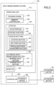
- FIG. 2 is a block diagram illustrating a configuration of the boat maneuvering device 100.
- the boat maneuvering device 100 includes an operating unit 110 that receives an operation by the operator.
- the operating unit 110 is provided in, for example, a wheelhouse of the boat 10.
- the operating unit 110 includes a steering wheel 120, a remote controller 130, a joystick 140, an automatic boat maneuvering button 150, and a monitor 160.
- the steering wheel 120 is an operating device that performs a steering operation of the boat 10.
- the remote controller 130 is an operating device including, for example, a throttle lever to perform a shift operation and a propulsion force change operation of the boat 10.
- the monitor 160 includes, for example, a liquid crystal display to display various images (operational images, etc.) regarding the boat 10.
- the monitor 160 may include a touch panel.
- the joystick 140 is an operating device that operates the boat 10 in a joystick mode, and the like, described below.
- the joystick 140 is an example of an operating element.
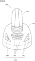
- FIG. 3 is an explanatory diagram illustrating an external configuration of the joystick 140.
- the joystick 140 includes a stick portion 141 held and operated by the operator and a support portion 142 supporting the stick portion 141 to enable a tilting operation and a twisting operation.
- the stick portion 141 is biased by a biasing member such as a spring to automatically return to a neutral state (the state where the stick portion 141 is in an upright position) when no operating force is applied.
- the stick portion 141 may be tilted in at least two directions to the front and back from the neutral state.
- the stick portion 141 may be tilted in three or more directions or may be tilted in all directions.
- the stick portion 141 enables a twisting operation in clockwise and counterclockwise directions.
- the magnitude and/or direction of the propulsion force generated by the outboard motor 30 is controlled in accordance with the tilt direction and amount of the stick portion 141.
- the direction of the propulsion force generated by the outboard motor 30 is controlled to move the boat 10 forward.
- the direction of the propulsion force generated by the outboard motor 30 is controlled to move the boat 10 backward.
- the control is performed such that the larger the tilt amount of the stick portion 141, the larger the propulsion force generated by the outboard motor 30.
- the direction of the propulsion force generated by the outboard motor 30 is controlled such that the boat 10 is steered in accordance with the rotation direction and amount of the stick portion 141.
- the joystick 140 further includes various buttons 143.
- the various buttons 143 include a joystick button 144, a set point button 145, and a propulsion force adjustment button 146.
- the joystick button 144 is a button to perform, for example, the operation to shift to the joystick mode described below.
- the set point button 145 is a button to perform, for example, the operation to shift to a set point mode described below.
- the set point mode is a collective term for a stay point mode, a drift point mode, and a fish point mode
- the set point button 145 includes buttons corresponding to the respective modes.
- the automatic boat maneuvering button 150 is a button to perform the operation to shift to an automatic boat maneuvering mode described below.
- the automatic boat maneuvering mode is a collective term for a bearing hold mode and a course hold mode
- the automatic boat maneuvering button 150 includes buttons (a bearing hold button 151 and a course hold button 152) corresponding to the respective modes.
- the boat maneuvering device 100 further includes a controller 180.
- the controller 180 includes, for example, a CPU, a multi-core CPU, a programmable device (field programmable gate array (FPGA), programmable logic device (PLD), etc.).
- the controller 180 controls the operation of the boat 10.
- the controller 180 controls the magnitude and the direction of the propulsion force generated by the outboard motor 30 of the boat 10 in response to the operation on the operating unit 110.
- the controller 180 controls the magnitude and the direction of the propulsion force generated by the outboard motor 30 in response to the operation on the joystick 140.
- the controller 180 includes a storage device 182.
- the storage device 182 includes, for example, a ROM, a RAM, a hard disk drive (HDD), a solid state drive (SSD), etc.
- the storage device 182 stores various types of programs and data and is used as a work area for executing various processes and a storage area of data.
- the storage device 182 stores a computer program for executing a boat maneuvering mode switching process described below.
- the computer program is provided in the state of being stored in a computer-readable recording medium (not illustrated), such as a CD-ROM, DVD-ROM, or USB memory or is provided in the state of being acquirable from an external device (e.g., a server in the cloud) via a communication interface (not illustrated) and is stored in the storage device 182 in the state of being operable on the boat maneuvering device 100.
- a computer-readable recording medium such as a CD-ROM, DVD-ROM, or USB memory
- an external device e.g., a server in the cloud
- a communication interface not illustrated
- the boat maneuvering mode switching process is a process to switch the boat maneuvering mode of the boat 10.
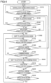
- FIG. 4 is a flowchart illustrating the boat maneuvering mode switching process
- FIG. 5 is a transition diagram of the boat maneuvering mode during the boat maneuvering mode switching process.
- the controller 180 sets the boat maneuvering mode to a normal boat maneuvering mode M0 by default (S110).
- the normal boat maneuvering mode M0 is a mode for boat maneuvering by primarily using the steering wheel 120 and the remote controller 130.
- the controller 180 monitors whether a joystick mode start operation has been performed by the operator (S120) and, when the joystick mode start operation has been performed (S120: YES), shifts the boat maneuvering mode from the normal boat maneuvering mode M0 to a joystick mode M1 (S130, see a1 in FIG. 5 ).
- the joystick mode M1 is a mode for boat maneuvering using the joystick 140.
- the joystick mode M1 is used, for example, when the boat 10 is propelled at a relatively low speed (e.g., approximately 10 km/h or less).
- the driving force generated by the power source 32 of the outboard motor 30 may be limited to a predetermined value or less.
- the engine speed may be limited to approximately 2000 rpm or less in the joystick mode M1.
- the above-described joystick mode start operation is, for example, a short press of the joystick button 144.
- a short press is an operation to press the button for a predetermined time or less.
- the shift is made to the joystick mode M1 only when the joystick mode start operation is performed in a state where a predetermined requirement is satisfied.
- the state where the predetermined requirement is satisfied refers to, for example, the state where the propulsion force generated by the outboard motor 30 is zero.
- the controller 180 monitors whether a joystick mode stop operation has been performed by the operator (S140) and, when the joystick mode stop operation has been performed (S140: YES), shifts the boat maneuvering mode from the joystick mode M1 to the normal boat maneuvering mode M0 (S110, see a2 in FIG. 5 ).
- the joystick mode stop operation is, for example, a short press of the joystick button 144.
- the controller 180 monitors whether a hold start operation has been performed by the operator (S150) and, when the hold start operation has been performed (S150: YES), shifts the boat maneuvering mode from the joystick mode M1 to a joystick hold mode M10 (S160, see a3 in FIG. 5 ).
- the joystick hold mode M10 the output signal of the joystick 140 at the time of the hold start operation (the signal indicating the tilt state of the stick portion 141) is held.
- the controller 180 performs a hold control to hold the index (e.g., throttle valve opening degree, engine speed, or motor output) correlated with the magnitude of the propulsion force generated by the outboard motor 30.
- the index e.g., throttle valve opening degree, engine speed, or motor output
- the operator does not need to apply the force to the stick portion 141 to continuously tilt the stick portion 141 and may execute boat maneuvering with his/her hands off the stick portion 141, which may reduce the onerousness for boat maneuvering.
- the above-described hold start operation is, for example, a long press of the joystick button 144.
- a long press is an operation to press the button for a predetermined time or more.
- the joystick mode M1 shifts to the joystick hold mode M10 only when the hold start operation is performed in a state where a predetermined requirement is satisfied.
- the state where the predetermined requirement is satisfied refers to, for example, the state where the stick portion 141 of the joystick 140 is tilted substantially forward or substantially backward.
- the joystick hold mode M10 and a joystick hold combined mode M11 described below are collectively referred to as a joystick hold mode group.
- the boat maneuvering state in the joystick hold mode M10 is an example of a first boat maneuvering state.
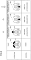
- FIG. 6 is an explanatory diagram illustrating control contents in response to operations on the joystick 140 in the joystick hold mode M10.
- the controller 180 changes the direction of the propulsion force generated by the outboard motor 30 such that the boat 10 is steered in accordance with the rotation direction and amount of the stick portion 141.
- the steering operation may be not only the twisting operation of the stick portion 141 but also other operations (e.g., the operation to tilt the stick portion 141 in the steering direction).
- the controller 180 increases the magnitude of the index (e.g., throttle valve opening degree, engine speed, motor output, etc.) correlated with the magnitude of the propulsion force generated by the outboard motor 30 in steps in accordance with the number of times of the acceleration operation to increase the velocity of the boat 10.
- a short tilt is the operation to tilt the stick portion 141 for a predetermined time or less.
- the magnitude of the above-described index increases in one step and the boat 10 accelerates in one step when the acceleration operation is performed once, and the magnitude of the above-described index increases in two steps and the boat 10 accelerates in two steps when the acceleration operation is performed twice.
- the controller 180 decreases the magnitude of the index correlated with the magnitude of the propulsion force generated by the outboard motor 30 in steps in accordance with the number of times of the deceleration operation to decrease the velocity of the boat 10. For example, the magnitude of the above-described index decreases in one step and the boat 10 decelerates in one step when the deceleration operation is performed once, and the magnitude of the above-described index decreases in two steps and the boat 10 decelerates in two steps when the deceleration operation is performed twice.
- the acceleration/deceleration operation while the boat 10 moves backward is an operation opposite to the acceleration/deceleration operation while the boat 10 moves forward. Specifically, the acceleration operation while the boat 10 moves backward is a backward short tilting operation of the stick portion 141, and the deceleration operation while the boat 10 moves backward is a forward short tilting operation of the stick portion 141.
- the controller 180 executes steering and acceleration/deceleration of the boat 10 while maintaining the joystick hold mode M10. Therefore, the operator may make fine adjustments to boat maneuvering in the joystick hold mode M10.
- the controller 180 monitors whether the hold stop operation has been performed by the operator (S170) and, when the hold stop operation has been performed (S170: YES), shifts the boat maneuvering mode from the joystick hold mode M10 to the joystick mode M1 (S130, see a4 in FIG. 5 ).
- the hold stop operation is, for example, a short press of the joystick button 144.
- the backward long tilting operation of the stick portion 141 while the boat 10 moves forward and also the forward long tilting operation of the stick portion 141 while the boat 10 moves backward are recognized as a hold stop operation.
- a long tilt is an operation to tilt the stick portion 141 for a predetermined time or more.
- the controller 180 monitors whether a joystick cancel condition is satisfied (S180) and, when the joystick cancel condition is satisfied (S180: YES), shifts the boat maneuvering mode from the joystick hold mode M10 to the normal boat maneuvering mode M0 (S110, see a5 in FIG. 5 ).
- the joystick cancel condition includes that, for example, the operation has been performed on the remote controller 130 or the steering wheel 120, the power source 32 of the outboard motor 30 has stopped, and an error such as a communication error of the joystick 140 has occurred.
- a shift to the normal boat maneuvering mode M0 when the joystick cancel condition is satisfied is made in not only the joystick hold mode M10 but also the joystick mode M1.
- the controller 180 monitors whether a combined mode start condition is satisfied (S190) and, when the combined mode start condition is satisfied (S190: YES), shifts the boat maneuvering mode from the joystick hold mode M10 to the joystick hold combined mode M11 (S200, see a6 to a8 in FIG. 5 ).
- the joystick hold combined mode M11 is a mode that, together with the joystick hold mode M10, forms the joystick hold mode group and that executes other controls in addition to the above-described hold control (control to hold the index correlated with the magnitude of the propulsion force generated by the outboard motor 30).
- a joystick hold + bearing hold mode M13 a joystick hold + course hold mode M14
- a joystick hold + pattern shift mode M15 are prepared as the joystick hold combined mode M11.
- the joystick hold + bearing hold mode M13 is a mode for executing a bearing hold control to hold the bearing of the boat 10 in addition to the above-described hold control. In this mode, the controller 180 controls the magnitude and the direction of the propulsion force generated by the outboard motor 30 such that the bearing of the boat 10 is held.
- the joystick hold + bearing hold mode M13 includes, in addition to the hold control and the bearing hold control described above, a mode (joystick hold + bearing hold + pattern shift mode) for also executing the pattern control described below.
- the joystick hold + course hold mode M14 is a mode for executing, in addition to the above-described hold control, a course hold control to hold the course of the boat 10.
- the controller 180 controls the magnitude and the direction of the propulsion force generated by the outboard motor 30 to hold the course of the boat 10.
- the joystick hold + course hold mode M14 includes, in addition to the hold control and the course hold control described above, the mode (joystick hold + course hold + pattern shift mode) for also executing the pattern control described below.
- the bearing hold control and the course hold control are collectively referred to as an automatic boat maneuvering control
- the joystick hold + bearing hold mode M13 and the joystick hold + course hold mode M14 are collectively referred to as a joystick hold automatic boat maneuvering mode M12.
- a combined mode start condition for a shift from the joystick hold mode M10 to the joystick hold automatic boat maneuvering mode M12 includes, for example, that the automatic boat maneuvering button 150 (the bearing hold button 151 or the course hold button 152) has been pressed.
- a boat maneuvering state in the joystick hold automatic boat maneuvering mode M12 is an example of a second boat maneuvering state, and the press of the automatic boat maneuvering button 150 is an example of an automatic boat maneuvering start operation.
- the joystick hold + pattern shift mode M15 included in the joystick hold combined mode M11, is a mode for executing, in addition to the above-described hold control, a pattern control to alternately switch between an on state where the outboard motor 30 generates the propulsion force and an off state where the outboard motor 30 does not generate the propulsion force. According to this mode, the boat 10 may be maneuvered at an extremely low speed.
- the combined mode start condition for a shift from the joystick hold mode M10 to the joystick hold + pattern shift mode M15 includes, for example, that the velocity of the boat 10 is less than a predetermined value (e.g., less than approximately 3 km/h).
- the boat maneuvering state in the joystick hold + pattern shift mode M15 is an example of a third boat maneuvering state.
- the controller 180 monitors whether the hold stop operation has been performed by the operator (S210) and, when the hold stop operation has been performed (S210: YES), shifts the boat maneuvering mode from the joystick hold combined mode M11 to the joystick mode M1 (S130, see a4 in FIG. 5 ). Moreover, in the joystick hold combined mode M11, as in the joystick hold mode M10, the controller 180 monitors whether the joystick cancel condition is satisfied (S220) and, when the joystick cancel condition is satisfied (S220: YES), shifts the boat maneuvering mode from the joystick hold combined mode M11 to the normal boat maneuvering mode M0 (S110, see a5 in FIG. 5 ).
- the controller 180 monitors whether a single mode return condition is satisfied (S230) and, when the single mode return condition is satisfied (S230: YES), shifts the boat maneuvering mode from the joystick hold combined mode M11 to the joystick hold mode M10 (S160, see a9 to a11 in FIG. 5 ).
- the single mode return condition includes that the active automatic boat maneuvering button 150 (the bearing hold button 151 or the course hold button 152) has been pressed. That is, in the joystick hold + bearing hold mode M13, the press of the bearing hold button 151 is recognized as a single mode return condition. Similarly, in the joystick hold + course hold mode M14, the press of the course hold button 152 is recognized as a single mode return condition.
- the single mode return condition includes that the steering operation on the joystick 140 (at least either one of the twisting operation of the stick portion 141 and the tilting operation of the stick portion 141 in the steering direction) has been performed. Therefore, when the steering operation is performed on the joystick 140 in the joystick hold automatic boat maneuvering mode M12, the boat maneuvering mode shifts to the joystick hold mode M10. Thus, the automatic boat maneuvering control is temporarily stopped, and the steering control is executed in response to the steering operation on the joystick 140. Then, when the steering operation on the joystick 140 is stopped, it is determined that the combined mode start condition is satisfied (S190: YES), and the boat maneuvering mode shifts to the joystick hold combined mode M11.
- the combined mode start condition S190: YES
- the steering operation is performed on the joystick 140 during boat maneuvering in the joystick hold combined mode M11 and thus a manual steering operation is temporarily performed, and then the steering operation on the joystick 140 is stopped to enable a return to automatic boat maneuvering, which may improve the boat maneuverability.
- the single mode return condition includes that the velocity of the boat 10 is a predetermined value or more (e.g., approximately 3 km/h or more).
- a set point mode M2 is set as a boat maneuvering mode.
- the set point mode M2 is a collective term for the stay point mode, the drift point mode, and the fish point mode.
- the stay point mode is a mode for holding the position and bearing of the boat 10
- the fish point mode is a mode for holding the position of the boat 10
- the drift point mode is a mode for holding the bearing of the boat 10.
- the controller 180 repeatedly performs the above-described process.
- a predetermined end condition e.g., a primary switch of the boat 10 is in the off state
- the boat maneuvering mode switching process by the controller 180 ends.
- the boat 10 includes the two outboard motors 30, but the boat 10 may include the one outboard motor 30, or the boat 10 may include the three or more outboard motors 30.
- the operating unit 110 may include other elements.
- the configuration of the joystick 140 according to the above embodiment is merely an example and may be modified in various ways.
- the operating unit 110 includes the joystick 140 as an operating element, but the operating unit 110 may include an operating element other than the joystick 140.
- the content of the boat maneuvering mode switching process according to the above embodiment is merely an example and may be modified in various ways.
- the index e.g., throttle valve opening degree, engine speed, motor power, etc.
- the velocity of the boat 10 may be held.
- both the steering operation and the acceleration/deceleration operation for the joystick 140 are possible, but at least either one of the steering operation and the acceleration/deceleration operation for the joystick 140 may be possible.
- the controller 180 may change at least either one of the magnitude and the direction of the propulsion force generated by the outboard motor 30 while maintaining the joystick hold mode M10.
- each boat maneuvering mode and the shift condition for each boat maneuvering mode are merely examples and may be modified in various ways. According to the above embodiment, a part of the boat maneuvering modes may be omitted or other boat maneuvering modes may be included.
Landscapes
- Chemical & Material Sciences (AREA)
- Engineering & Computer Science (AREA)
- Combustion & Propulsion (AREA)
- Mechanical Engineering (AREA)
- Ocean & Marine Engineering (AREA)
- Mechanical Control Devices (AREA)
Abstract
Description
- The present invention relates to a boat maneuvering device, a boat and a boat maneuvering method.
- Boats are maneuvered by using, for example, a remote controller and a steering wheel. For example, there are known boats that may be maneuvered with an operating element (e.g., joystick) during low-speed propulsion.
- There are conventionally discussed techniques that, in order to improve the boat maneuverability with the operating element, perform a hold control to hold the output signal of the operating element at the time when a predetermined switch is pressed during boat maneuvering with the operating element (e.g., see
JP S60-166043 U - It is the object of the present invention to provided boat maneuvering device, a boat and boat maneuvering method being able to make fine adjustments to boat maneuvering during the hold control.
- According to the present invention said object is solved by a boat maneuvering device having the features of independent claim 1. Moreover, said object is solved by a boat maneuvering method having the features of independent claim 15. Furthermore, said object is solved by a boat according to claim 14. Preferred embodiments are laid down in the dependent claims.
- The present disclosure may be implemented as the following aspects, for example.
- (1) A boat maneuvering device disclosed in this description includes an operating unit including an operating element, and a controller that controls a magnitude and a direction of a propulsion force generated by a propulsion device of a boat in response to an operation on the operating unit. When a hold start operation is performed on the operating unit during boat maneuvering using the operating element, the controller shifts to a first boat maneuvering state to perform a hold control to hold a control index that is at least either one of an index correlated with the magnitude of the propulsion force generated by the propulsion device and a velocity of the boat. When a steering operation is performed on the operating element in the first boat maneuvering state, the controller changes the direction of the propulsion force generated by the propulsion device while maintaining the first boat maneuvering state.
With this boat maneuvering device, when the hold start operation is performed on the operating unit during boat maneuvering using the operating element, the first boat maneuvering state is set to perform the hold control to hold the control index that is at least either one of the index correlated with the magnitude of the propulsion force generated by the propulsion device and the velocity of the boat, and therefore there is no need to continuously perform the operation on the operating element to maintain the velocity of the boat and the boat maneuverability may be improved. Furthermore, with this boat maneuvering device, when the steering operation is performed on the operating element in the first boat maneuvering state, the direction of the propulsion force generated by the propulsion device is changed while the first boat maneuvering state is maintained so that the desired course may be selected even in the first boat maneuvering state and the boat maneuverability using the operating element may be further improved. - (2) The above-described boat maneuvering device may have a configuration such that the steering operation is at least either one of a twisting operation of the operating element and a tilting operation of the operating element in a steering direction. The use of this configuration may achieve a more intuitive steering operation in the first boat maneuvering state where the hold control is performed and may further improve the boat maneuverability using the operating element.
- (3) The above-described boat maneuvering device may have a configuration such that, when an acceleration or deceleration operation is performed on the operating element in the first boat maneuvering state, the controller changes the magnitude of the control index held during the hold control. The use of this configuration may achieve fine adjustments to the velocity of the boat even in the first boat maneuvering state and may further improve the boat maneuverability using the operating element as the magnitude of the control index held during the hold control is changed when the acceleration/deceleration operation is performed on the operating element in the first boat maneuvering state.
- (4) The above-described boat maneuvering device may have a configuration such that the controller changes the magnitude of the control index held during the hold control in steps in accordance with the number of times of the acceleration or deceleration operation in the first boat maneuvering state. The use of this configuration may achieve easy fine adjustments to the velocity of the boat even in the first boat maneuvering state and may further improve the boat maneuverability using the operating element.
- (5) The above-described boat maneuvering device may have a configuration such that an acceleration operation is an operation to tilt the operating element in a traveling direction of the boat and a deceleration operation is an operation to tilt the operating element in a direction opposite to the traveling direction of the boat. The use of this configuration may achieve a more intuitive acceleration/deceleration operation in the first boat maneuvering state where the hold control is performed and may further improve the boat maneuverability using the operating element.
- (6) The above-described boat maneuvering device may have a configuration such that, when an automatic boat maneuvering start operation is performed on the operating unit in the first boat maneuvering state, the controller shifts to a second boat maneuvering state where, in addition to the hold control, an automatic boat maneuvering control is performed to hold a bearing or course of the boat. The use of this configuration may achieve a shift to the second boat maneuvering state where, in addition to the hold control, the automatic boat maneuvering control is performed to hold the bearing or course of the boat and may further improve the boat maneuverability using the operating element.
- (7) The above-described boat maneuvering device may have a configuration such that the controller shifts to the first boat maneuvering state when the steering operation is performed on the operating element in the second boat maneuvering state and returns to the second boat maneuvering state when the steering operation on the operating element is stopped. The use of this configuration may achieve a temporary steering operation in the second boat maneuvering state where, in addition to the hold control, the automatic boat maneuvering control is performed to hold the bearing or course of the boat and may further improve the boat maneuverability using the operating element.
- (8) The above-described boat maneuvering device may have a configuration such that the controller stops the hold control when a hold stop operation is performed on the operating element in the first boat maneuvering state. The use of this configuration may stop the hold control at the desired timing and may further improve the boat maneuverability using the operating element.
- (9) The above-described boat maneuvering device may have a configuration such that the hold stop operation is an operation to tilt the operating element backward for a predetermined time or more while the boat moves forward and is an operation to tilt the operating element forward for a predetermined time or more while the boat moves backward. The use of this configuration may achieve a more intuitive hold stop operation and may further improve the boat maneuverability using the operating element.
- (10) The above-described boat maneuvering device may have a configuration such that, when the velocity of the boat is less than a predetermined value in the first boat maneuvering state, the controller shifts to a third boat maneuvering state where, in addition to the hold control, a pattern control is performed to alternately switch between an on state where the propulsion device generates the propulsion force and an off state where the propulsion device does not generate the propulsion force and, when the velocity of the boat is the predetermined value or more, the controller returns to the first boat maneuvering state. The use of this configuration may achieve a shift from the first boat maneuvering state, in which the hold control is performed, to the third boat maneuvering state, in which the boat maneuvering is performed at a lower speed, and may further improve the boat maneuverability using the operating element.
- (11) The above-described boat maneuvering device may have a configuration such that the hold start operation is an operation to press a predetermined switch for a predetermined time or more. The use of this configuration may prevent an unintended shift (improper operation) to the first boat maneuvering state and may further improve the boat maneuverability using the operating element.
- (12) The above-described boat maneuvering device may have a configuration such that the operating element is a joystick including a stick portion gripped and operated by an operator and a support portion supporting the stick portion to enable a tilting operation and a twisting operation. The use of this configuration may further improve the boat maneuverability using the joystick.
- (13) Another boat maneuvering device disclosed in this description includes an operating unit including an operating element, and a controller that controls a magnitude and a direction of a propulsion force generated by a propulsion device of a boat in response to an operation on the operating unit. When a hold start operation is performed on the operating unit during boat maneuvering using the operating element, the controller shifts to a first boat maneuvering state to perform a hold control to hold a control index that is at least either one of an index correlated with the magnitude of the propulsion force generated by the propulsion device and a velocity of the boat. When an operation is performed on the operating element in the first boat maneuvering state, the controller changes at least either one of the magnitude and the direction of the propulsion force generated by the propulsion device while maintaining the first boat maneuvering state.
With this boat maneuvering device, when the hold start operation is performed on the operating unit during boat maneuvering using the operating element, the first boat maneuvering state is set to perform the hold control to hold the control index that is at least either one of the index correlated with the magnitude of the propulsion force generated by the propulsion device and the velocity of the boat, and therefore there is no need to continuously perform the operation on the operating element to maintain the velocity of the boat and the boat maneuverability may be improved. Furthermore, with this boat maneuvering device, when the operation is performed on the operating element in the first boat maneuvering state, at least either one of the magnitude and the direction of the propulsion force generated by the propulsion device is changed while the first boat maneuvering state is maintained so that the desired course may be selected even in the first boat maneuvering state and the boat maneuverability using the operating element may be further improved. - (14) A boat disclosed in this description includes a boat body, the propulsion device attached to the boat body, and the above-described boat maneuvering device. With this boat, the boat maneuverability using the operating element may be further improved.
- The technique disclosed in this description may be implemented in various forms, for example, in the form of a boat maneuvering device, a boat including a boat maneuvering device, or a boat maneuvering method.
- With the boat maneuvering device disclosed in this description, the boat maneuverability using the operating element may be further improved.
-
-
FIG. 1 is an explanatory diagram schematically illustrating a configuration of a boat according to the present embodiment. -
FIG. 2 is a block diagram illustrating a configuration of a boat maneuvering device. -
FIG. 3 is an explanatory diagram illustrating an external configuration of a joystick. -
FIG. 4 is a flowchart illustrating a boat maneuvering mode switching process. -
FIG. 5 is a transition diagram of a boat maneuvering mode during the boat maneuvering mode switching process. -
FIG. 6 is an explanatory diagram illustrating control contents in response to operations on the joystick in a joystick hold mode. -
FIG. 1 is an explanatory diagram schematically illustrating a configuration of aboat 10 according to the present embodiment.FIG. 1 illustrates arrows indicating the front (FRONT), the rear (REAR), the left (LEFT), and the right (RIGHT), respectively, with respect to the position of theboat 10. - As illustrated in
FIG. 1 , theboat 10 includes aboat body 20, anoutboard motor 30, and a boat maneuvering device orsystem 100. Theboat body 20 is a part of theboat 10 which a crew gets on. - The
outboard motor 30 is a device that generates the propulsion force for propelling theboat 10. Theoutboard motor 30 is attached to a rear portion of theboat body 20 via a bracket, for example. Theoutboard motor 30 includes apower source 32, such as an engine or motor, which generates the driving force, and a propulsionforce generating mechanism 34, such as a propeller, which is driven by the driving force from thepower source 32 to generate the propulsion force. Theoutboard motor 30 includes a steering mechanism and a shift mechanism, both of which are not illustrated. The steering mechanism rotates theoutboard motor 30 around a steering axis. The shift mechanism switches among a forward moving state where the driving force from thepower source 32 is transmitted to the propulsionforce generating mechanism 34 in the direction in which theboat 10 moves forward, a backward moving state where the driving force from thepower source 32 is transmitted to the propulsionforce generating mechanism 34 in the direction in which theboat 10 moves backward, and a neutral state where the driving force from thepower source 32 is not transmitted to the propulsionforce generating mechanism 34. According to the present embodiment, theboat 10 includes the twooutboard motors 30. Theoutboard motor 30 is an example of a propulsion device. - The
boat maneuvering device 100 is a device or system that operates theboat 10.FIG. 2 is a block diagram illustrating a configuration of theboat maneuvering device 100. As illustrated inFIGS. 1 and2 , theboat maneuvering device 100 includes anoperating unit 110 that receives an operation by the operator. Theoperating unit 110 is provided in, for example, a wheelhouse of theboat 10. Theoperating unit 110 includes asteering wheel 120, aremote controller 130, ajoystick 140, an automaticboat maneuvering button 150, and amonitor 160. - The
steering wheel 120 is an operating device that performs a steering operation of theboat 10. Theremote controller 130 is an operating device including, for example, a throttle lever to perform a shift operation and a propulsion force change operation of theboat 10. Themonitor 160 includes, for example, a liquid crystal display to display various images (operational images, etc.) regarding theboat 10. Themonitor 160 may include a touch panel. - The
joystick 140 is an operating device that operates theboat 10 in a joystick mode, and the like, described below. Thejoystick 140 is an example of an operating element. -
FIG. 3 is an explanatory diagram illustrating an external configuration of thejoystick 140. As illustrated inFIGS. 2 and3 , thejoystick 140 includes astick portion 141 held and operated by the operator and asupport portion 142 supporting thestick portion 141 to enable a tilting operation and a twisting operation. Thestick portion 141 is biased by a biasing member such as a spring to automatically return to a neutral state (the state where thestick portion 141 is in an upright position) when no operating force is applied. Thestick portion 141 may be tilted in at least two directions to the front and back from the neutral state. Thestick portion 141 may be tilted in three or more directions or may be tilted in all directions. Thestick portion 141 enables a twisting operation in clockwise and counterclockwise directions. - In the joystick mode, when the
stick portion 141 is tilted, the magnitude and/or direction of the propulsion force generated by theoutboard motor 30 is controlled in accordance with the tilt direction and amount of thestick portion 141. For example, when thestick portion 141 is tilted forward, the direction of the propulsion force generated by theoutboard motor 30 is controlled to move theboat 10 forward. Conversely, when thestick portion 141 is tilted backward, the direction of the propulsion force generated by theoutboard motor 30 is controlled to move theboat 10 backward. The control is performed such that the larger the tilt amount of thestick portion 141, the larger the propulsion force generated by theoutboard motor 30. When thestick portion 141 is twisted (rotated), the direction of the propulsion force generated by theoutboard motor 30 is controlled such that theboat 10 is steered in accordance with the rotation direction and amount of thestick portion 141. - The
joystick 140 further includesvarious buttons 143. Thevarious buttons 143 include ajoystick button 144, aset point button 145, and a propulsionforce adjustment button 146. Thejoystick button 144 is a button to perform, for example, the operation to shift to the joystick mode described below. Theset point button 145 is a button to perform, for example, the operation to shift to a set point mode described below. As described below, the set point mode is a collective term for a stay point mode, a drift point mode, and a fish point mode, and theset point button 145 includes buttons corresponding to the respective modes. - The automatic
boat maneuvering button 150 is a button to perform the operation to shift to an automatic boat maneuvering mode described below. As described below, the automatic boat maneuvering mode is a collective term for a bearing hold mode and a course hold mode, and the automaticboat maneuvering button 150 includes buttons (abearing hold button 151 and a course hold button 152) corresponding to the respective modes. - The
boat maneuvering device 100 further includes acontroller 180. Thecontroller 180 includes, for example, a CPU, a multi-core CPU, a programmable device (field programmable gate array (FPGA), programmable logic device (PLD), etc.). Thecontroller 180 controls the operation of theboat 10. For example, thecontroller 180 controls the magnitude and the direction of the propulsion force generated by theoutboard motor 30 of theboat 10 in response to the operation on theoperating unit 110. Thecontroller 180 controls the magnitude and the direction of the propulsion force generated by theoutboard motor 30 in response to the operation on thejoystick 140. - The
controller 180 includes astorage device 182. Thestorage device 182 includes, for example, a ROM, a RAM, a hard disk drive (HDD), a solid state drive (SSD), etc. Thestorage device 182 stores various types of programs and data and is used as a work area for executing various processes and a storage area of data. For example, thestorage device 182 stores a computer program for executing a boat maneuvering mode switching process described below. The computer program is provided in the state of being stored in a computer-readable recording medium (not illustrated), such as a CD-ROM, DVD-ROM, or USB memory or is provided in the state of being acquirable from an external device (e.g., a server in the cloud) via a communication interface (not illustrated) and is stored in thestorage device 182 in the state of being operable on theboat maneuvering device 100. - Next, the boat maneuvering mode switching process executed by the
controller 180 of theboat maneuvering device 100 will be described. The boat maneuvering mode switching process is a process to switch the boat maneuvering mode of theboat 10.FIG. 4 is a flowchart illustrating the boat maneuvering mode switching process, andFIG. 5 is a transition diagram of the boat maneuvering mode during the boat maneuvering mode switching process. - According to the present embodiment, the
controller 180 sets the boat maneuvering mode to a normal boat maneuvering mode M0 by default (S110). The normal boat maneuvering mode M0 is a mode for boat maneuvering by primarily using thesteering wheel 120 and theremote controller 130. - In the normal boat maneuvering mode M0, the
controller 180 monitors whether a joystick mode start operation has been performed by the operator (S120) and, when the joystick mode start operation has been performed (S120: YES), shifts the boat maneuvering mode from the normal boat maneuvering mode M0 to a joystick mode M1 (S130, see a1 inFIG. 5 ). The joystick mode M1 is a mode for boat maneuvering using thejoystick 140. The joystick mode M1 is used, for example, when theboat 10 is propelled at a relatively low speed (e.g., approximately 10 km/h or less). In the joystick mode M1, the driving force generated by thepower source 32 of theoutboard motor 30 may be limited to a predetermined value or less. For example, when thepower source 32 includes an engine, the engine speed may be limited to approximately 2000 rpm or less in the joystick mode M1. The above-described joystick mode start operation is, for example, a short press of thejoystick button 144. A short press is an operation to press the button for a predetermined time or less. According to the present embodiment, the shift is made to the joystick mode M1 only when the joystick mode start operation is performed in a state where a predetermined requirement is satisfied. The state where the predetermined requirement is satisfied refers to, for example, the state where the propulsion force generated by theoutboard motor 30 is zero. - In the joystick mode M1, the
controller 180 monitors whether a joystick mode stop operation has been performed by the operator (S140) and, when the joystick mode stop operation has been performed (S140: YES), shifts the boat maneuvering mode from the joystick mode M1 to the normal boat maneuvering mode M0 (S110, see a2 inFIG. 5 ). The joystick mode stop operation is, for example, a short press of thejoystick button 144. - In the joystick mode M1, the
controller 180 monitors whether a hold start operation has been performed by the operator (S150) and, when the hold start operation has been performed (S150: YES), shifts the boat maneuvering mode from the joystick mode M1 to a joystick hold mode M10 (S160, see a3 inFIG. 5 ). In the joystick hold mode M10, the output signal of thejoystick 140 at the time of the hold start operation (the signal indicating the tilt state of the stick portion 141) is held. Thus, thecontroller 180 performs a hold control to hold the index (e.g., throttle valve opening degree, engine speed, or motor output) correlated with the magnitude of the propulsion force generated by theoutboard motor 30. In the joystick hold mode M10, the operator does not need to apply the force to thestick portion 141 to continuously tilt thestick portion 141 and may execute boat maneuvering with his/her hands off thestick portion 141, which may reduce the onerousness for boat maneuvering. The above-described hold start operation is, for example, a long press of thejoystick button 144. A long press is an operation to press the button for a predetermined time or more. According to the present embodiment, the joystick mode M1 shifts to the joystick hold mode M10 only when the hold start operation is performed in a state where a predetermined requirement is satisfied. The state where the predetermined requirement is satisfied refers to, for example, the state where thestick portion 141 of thejoystick 140 is tilted substantially forward or substantially backward. The joystick hold mode M10 and a joystick hold combined mode M11 described below are collectively referred to as a joystick hold mode group. The boat maneuvering state in the joystick hold mode M10 is an example of a first boat maneuvering state. - According to the present embodiment, in the joystick hold mode M10, an operation is performed on the
joystick 140 so that fine adjustments may be made to boat maneuvering.FIG. 6 is an explanatory diagram illustrating control contents in response to operations on thejoystick 140 in the joystick hold mode M10. - When the twisting (rotating) operation is performed on the
stick portion 141 as a steering operation in the joystick hold mode M10, thecontroller 180 changes the direction of the propulsion force generated by theoutboard motor 30 such that theboat 10 is steered in accordance with the rotation direction and amount of thestick portion 141. The steering operation may be not only the twisting operation of thestick portion 141 but also other operations (e.g., the operation to tilt thestick portion 141 in the steering direction). - When a forward short tilting operation is performed on the
stick portion 141 as an acceleration operation while theboat 10 moves forward, thecontroller 180 increases the magnitude of the index (e.g., throttle valve opening degree, engine speed, motor output, etc.) correlated with the magnitude of the propulsion force generated by theoutboard motor 30 in steps in accordance with the number of times of the acceleration operation to increase the velocity of theboat 10. A short tilt is the operation to tilt thestick portion 141 for a predetermined time or less. For example, the magnitude of the above-described index increases in one step and theboat 10 accelerates in one step when the acceleration operation is performed once, and the magnitude of the above-described index increases in two steps and theboat 10 accelerates in two steps when the acceleration operation is performed twice. - When a backward short tilting operation is performed on the
stick portion 141 as a deceleration operation while theboat 10 moves forward, thecontroller 180 decreases the magnitude of the index correlated with the magnitude of the propulsion force generated by theoutboard motor 30 in steps in accordance with the number of times of the deceleration operation to decrease the velocity of theboat 10. For example, the magnitude of the above-described index decreases in one step and theboat 10 decelerates in one step when the deceleration operation is performed once, and the magnitude of the above-described index decreases in two steps and theboat 10 decelerates in two steps when the deceleration operation is performed twice. - The acceleration/deceleration operation while the
boat 10 moves backward is an operation opposite to the acceleration/deceleration operation while theboat 10 moves forward. Specifically, the acceleration operation while theboat 10 moves backward is a backward short tilting operation of thestick portion 141, and the deceleration operation while theboat 10 moves backward is a forward short tilting operation of thestick portion 141. - As described above, according to the present embodiment, when the steering operation or the acceleration/deceleration operation is performed on the
joystick 140 in the joystick hold mode M10, thecontroller 180 executes steering and acceleration/deceleration of theboat 10 while maintaining the joystick hold mode M10. Therefore, the operator may make fine adjustments to boat maneuvering in the joystick hold mode M10. - In the joystick hold mode M10, the
controller 180 monitors whether the hold stop operation has been performed by the operator (S170) and, when the hold stop operation has been performed (S170: YES), shifts the boat maneuvering mode from the joystick hold mode M10 to the joystick mode M1 (S130, see a4 inFIG. 5 ). The hold stop operation is, for example, a short press of thejoystick button 144. According to the present embodiment, as illustrated inFIG. 6 , the backward long tilting operation of thestick portion 141 while theboat 10 moves forward and also the forward long tilting operation of thestick portion 141 while theboat 10 moves backward are recognized as a hold stop operation. A long tilt is an operation to tilt thestick portion 141 for a predetermined time or more. - In the joystick hold mode M10, the
controller 180 monitors whether a joystick cancel condition is satisfied (S180) and, when the joystick cancel condition is satisfied (S180: YES), shifts the boat maneuvering mode from the joystick hold mode M10 to the normal boat maneuvering mode M0 (S110, see a5 inFIG. 5 ). The joystick cancel condition includes that, for example, the operation has been performed on theremote controller 130 or thesteering wheel 120, thepower source 32 of theoutboard motor 30 has stopped, and an error such as a communication error of thejoystick 140 has occurred. A shift to the normal boat maneuvering mode M0 when the joystick cancel condition is satisfied is made in not only the joystick hold mode M10 but also the joystick mode M1. - In the joystick hold mode M10, the
controller 180 monitors whether a combined mode start condition is satisfied (S190) and, when the combined mode start condition is satisfied (S190: YES), shifts the boat maneuvering mode from the joystick hold mode M10 to the joystick hold combined mode M11 (S200, see a6 to a8 inFIG. 5 ). The joystick hold combined mode M11 is a mode that, together with the joystick hold mode M10, forms the joystick hold mode group and that executes other controls in addition to the above-described hold control (control to hold the index correlated with the magnitude of the propulsion force generated by the outboard motor 30). - As illustrated in
FIG. 5 , according to the present embodiment, three modes, that is, a joystick hold + bearing hold mode M13, a joystick hold + course hold mode M14, and a joystick hold + pattern shift mode M15 are prepared as the joystick hold combined mode M11. - The joystick hold + bearing hold mode M13 is a mode for executing a bearing hold control to hold the bearing of the
boat 10 in addition to the above-described hold control. In this mode, thecontroller 180 controls the magnitude and the direction of the propulsion force generated by theoutboard motor 30 such that the bearing of theboat 10 is held. According to the present embodiment, as illustrated inFIG. 5 , the joystick hold + bearing hold mode M13 includes, in addition to the hold control and the bearing hold control described above, a mode (joystick hold + bearing hold + pattern shift mode) for also executing the pattern control described below. The joystick hold + course hold mode M14 is a mode for executing, in addition to the above-described hold control, a course hold control to hold the course of theboat 10. In this mode, thecontroller 180 controls the magnitude and the direction of the propulsion force generated by theoutboard motor 30 to hold the course of theboat 10. According to the present embodiment, as illustrated inFIG. 5 , the joystick hold + course hold mode M14 includes, in addition to the hold control and the course hold control described above, the mode (joystick hold + course hold + pattern shift mode) for also executing the pattern control described below. In this description, the bearing hold control and the course hold control are collectively referred to as an automatic boat maneuvering control, and the joystick hold + bearing hold mode M13 and the joystick hold + course hold mode M14 are collectively referred to as a joystick hold automatic boat maneuvering mode M12. A combined mode start condition for a shift from the joystick hold mode M10 to the joystick hold automatic boat maneuvering mode M12 includes, for example, that the automatic boat maneuvering button 150 (thebearing hold button 151 or the course hold button 152) has been pressed. A boat maneuvering state in the joystick hold automatic boat maneuvering mode M12 is an example of a second boat maneuvering state, and the press of the automaticboat maneuvering button 150 is an example of an automatic boat maneuvering start operation. - The joystick hold + pattern shift mode M15, included in the joystick hold combined mode M11, is a mode for executing, in addition to the above-described hold control, a pattern control to alternately switch between an on state where the
outboard motor 30 generates the propulsion force and an off state where theoutboard motor 30 does not generate the propulsion force. According to this mode, theboat 10 may be maneuvered at an extremely low speed. The combined mode start condition for a shift from the joystick hold mode M10 to the joystick hold + pattern shift mode M15 includes, for example, that the velocity of theboat 10 is less than a predetermined value (e.g., less than approximately 3 km/h). The boat maneuvering state in the joystick hold + pattern shift mode M15 is an example of a third boat maneuvering state. - In the joystick hold combined mode M11, as in the joystick hold mode M10, the
controller 180 monitors whether the hold stop operation has been performed by the operator (S210) and, when the hold stop operation has been performed (S210: YES), shifts the boat maneuvering mode from the joystick hold combined mode M11 to the joystick mode M1 (S130, see a4 inFIG. 5 ). Moreover, in the joystick hold combined mode M11, as in the joystick hold mode M10, thecontroller 180 monitors whether the joystick cancel condition is satisfied (S220) and, when the joystick cancel condition is satisfied (S220: YES), shifts the boat maneuvering mode from the joystick hold combined mode M11 to the normal boat maneuvering mode M0 (S110, see a5 inFIG. 5 ). - In the joystick hold combined mode M11, the
controller 180 monitors whether a single mode return condition is satisfied (S230) and, when the single mode return condition is satisfied (S230: YES), shifts the boat maneuvering mode from the joystick hold combined mode M11 to the joystick hold mode M10 (S160, see a9 to a11 inFIG. 5 ). - For example, in the joystick hold automatic boat maneuvering mode M12, included in the joystick hold combined mode M11, the single mode return condition includes that the active automatic boat maneuvering button 150 (the
bearing hold button 151 or the course hold button 152) has been pressed. That is, in the joystick hold + bearing hold mode M13, the press of thebearing hold button 151 is recognized as a single mode return condition. Similarly, in the joystick hold + course hold mode M14, the press of thecourse hold button 152 is recognized as a single mode return condition. - Furthermore, in the joystick hold automatic boat maneuvering mode M12, the single mode return condition includes that the steering operation on the joystick 140 (at least either one of the twisting operation of the
stick portion 141 and the tilting operation of thestick portion 141 in the steering direction) has been performed. Therefore, when the steering operation is performed on thejoystick 140 in the joystick hold automatic boat maneuvering mode M12, the boat maneuvering mode shifts to the joystick hold mode M10. Thus, the automatic boat maneuvering control is temporarily stopped, and the steering control is executed in response to the steering operation on thejoystick 140. Then, when the steering operation on thejoystick 140 is stopped, it is determined that the combined mode start condition is satisfied (S190: YES), and the boat maneuvering mode shifts to the joystick hold combined mode M11. As described above, the steering operation is performed on thejoystick 140 during boat maneuvering in the joystick hold combined mode M11 and thus a manual steering operation is temporarily performed, and then the steering operation on thejoystick 140 is stopped to enable a return to automatic boat maneuvering, which may improve the boat maneuverability. - For example, in the joystick hold + pattern shift mode M15, included in the joystick hold combined mode M11, the single mode return condition includes that the velocity of the
boat 10 is a predetermined value or more (e.g., approximately 3 km/h or more). - As illustrated in
FIG. 5 , according to the present embodiment, it is possible to make a direct shift between the joystick hold + bearing hold mode M13 and the joystick hold + course hold mode M14 (see a12 and a13 inFIG. 5 ). Specifically, when thecourse hold button 152 is pressed in the joystick hold + bearing hold mode M13, a shift is made to the joystick hold + course hold mode M14. Conversely, when thebearing hold button 151 is pressed in the joystick hold + course hold mode M14, a shift is made to the joystick hold + bearing hold mode M13. - As illustrated in
FIG. 5 , according to the present embodiment, a set point mode M2 is set as a boat maneuvering mode. As described above, the set point mode M2 is a collective term for the stay point mode, the drift point mode, and the fish point mode. The stay point mode is a mode for holding the position and bearing of theboat 10, the fish point mode is a mode for holding the position of theboat 10, and the drift point mode is a mode for holding the bearing of theboat 10. When theset point button 145 is pressed in the joystick mode M1, a shift is made to the set point mode M2 (see a14 inFIG. 5 ), and when theset point button 145 is pressed in the set point mode M2, a shift is made to the joystick mode M1 (see a15 inFIG. 5 ). Similarly, when theset point button 145 is pressed in the joystick hold mode M10 and the joystick hold combined mode M11, a shift is made to the set point mode M2 (see a16 inFIG. 5 ). - The
controller 180 repeatedly performs the above-described process. When a predetermined end condition is satisfied (e.g., a primary switch of theboat 10 is in the off state), the boat maneuvering mode switching process by thecontroller 180 ends. - The technique disclosed in this description is not limited to the embodiment described above and may be modified to various forms without departing from the spirit thereof and for example may be modified as described below.
- The configuration of the
boat 10 according to the above embodiment is merely an example and may be modified in various ways. For example, according to the above embodiment, theboat 10 includes the twooutboard motors 30, but theboat 10 may include the oneoutboard motor 30, or theboat 10 may include the three or moreoutboard motors 30. - According to the above embodiment, a part of the elements included in the
operating unit 110 may be omitted, or theoperating unit 110 may include other elements. The configuration of thejoystick 140 according to the above embodiment is merely an example and may be modified in various ways. According to the above embodiment, theoperating unit 110 includes thejoystick 140 as an operating element, but theoperating unit 110 may include an operating element other than thejoystick 140. - The content of the boat maneuvering mode switching process according to the above embodiment is merely an example and may be modified in various ways. For example, according to the above embodiment, the index (e.g., throttle valve opening degree, engine speed, motor power, etc.) correlated with the magnitude of the propulsion force generated by the
outboard motor 30 is held during the hold control, but along with or instead of it, the velocity of theboat 10 may be held. - According to the above embodiment, in the joystick hold mode M10, both the steering operation and the acceleration/deceleration operation for the
joystick 140 are possible, but at least either one of the steering operation and the acceleration/deceleration operation for thejoystick 140 may be possible. Specifically, in the joystick hold mode M10, when an operation is performed on thejoystick 140, thecontroller 180 may change at least either one of the magnitude and the direction of the propulsion force generated by theoutboard motor 30 while maintaining the joystick hold mode M10. - According to the above embodiment, the start and stop operation of each boat maneuvering mode and the shift condition for each boat maneuvering mode are merely examples and may be modified in various ways. According to the above embodiment, a part of the boat maneuvering modes may be omitted or other boat maneuvering modes may be included.
Claims (15)
- A boat maneuvering device (100) for a boat (10) comprising:an operating unit (110) including an operating element (140); anda controller (180) configured to control a magnitude and a direction of a propulsion force generated by a propulsion device (30) of the boat (10) in response to an operation on the operating unit (110), whereinthe controller (180) is configured to shift to a first boat maneuvering state to perform a hold control to hold a control index that is at least either one of an index correlated with the magnitude of the propulsion force generated by the propulsion device (30) and a velocity of the boat (10), when a hold start operation is performed on the operating unit (110) during boat maneuvering using the operating element (140), and the controller (180) is configured to change at least either one of the magnitude and the direction of the propulsion force generated by the propulsion device (30) while maintaining the first boat maneuvering state, when an operation is performed on the operating element (140) in the first boat maneuvering state.
- The boat maneuvering device (100) according to claim 1, wherein the steering operation is at least either one of a twisting operation of the operating element (140) and a tilting operation of the operating element (140) in a steering direction.
- The boat maneuvering device (100) according to claim 1 or 2, wherein the controller (180) is configured to change the magnitude of the control index held during the hold control, when an acceleration or deceleration operation is performed on the operating element (140) in the first boat maneuvering state.
- The boat maneuvering device (100) according to claim 3, wherein the controller (180) is configured to changes the magnitude of the control index held during the hold control in steps in accordance with the number of times of the acceleration or deceleration operation in the first boat maneuvering state.
- The boat maneuvering device (100) according to claim 3 or 4, wherein the acceleration operation is an operation to tilt the operating element (140) in a traveling direction of the boat (10) and the deceleration operation is an operation to tilt the operating element (140) in a direction opposite to the traveling direction of the boat (10).
- The boat maneuvering device (100) according to any one of claims 1 to 5, wherein the controller (180) is configured to shift to a second boat maneuvering state where, in addition to the hold control, an automatic boat maneuvering control is performed to hold a bearing or course of the boat (10), when an automatic boat maneuvering start operation is performed on the operating unit (110) in the first boat maneuvering state.
- The boat maneuvering device (100) according to claim 6, wherein the controller (180) is configured to shift to the first boat maneuvering state when the steering operation is performed on the operating element (140) in the second boat maneuvering state and returns to the second boat maneuvering state when the steering operation on the operating element (140) is stopped.
- The boat maneuvering device (100) according to any one of claims 1 to 7, wherein the controller (180) is configured to stop the hold control when a hold stop operation is performed on the operating element (140) in the first boat maneuvering state.
- The boat maneuvering device (100) according to claim 8, wherein the hold stop operation is an operation to tilt the operating element (140) backward for a predetermined time or more while the boat (10) moves forward and is an operation to tilt the operating element (140) forward for a predetermined time or more while the boat (10) moves backward.
- The boat maneuvering device (100) according to any one of claims 1 to 9, wherein the controller (180) is configured to shift to a third boat maneuvering state where, in addition to the hold control, a pattern control is performed to alternately switch between an on state where the propulsion device (30) generates the propulsion force and an off state where the propulsion device (30) does not generate the propulsion force, when the velocity of the boat (10) is less than a predetermined value in the first boat maneuvering state, and, the controller (180) is configured to return to the first boat maneuvering state, when the velocity of the boat (10) is the predetermined value or more.
- The boat maneuvering device (100) according to any one of claims 1 to 10, wherein the hold start operation is an operation to press a predetermined switch for a predetermined time or more.
- The boat maneuvering device (100) according to any one of claims 1 to 11, wherein the operating element is a joystick (140) including a stick portion (141) gripped and operated by an operator and a support portion supporting the stick portion (141) to enable a tilting operation and a twisting operation.
- The boat maneuvering device (100) according to any one of claims 1 to 12, wherein the controller (180) is configured to change the direction of the propulsion force generated by the propulsion device (30) while maintaining the first boat maneuvering state, when a steering operation is performed on the operating element (140) in the first boat maneuvering state.
- A boat (10) comprising:a boat body (20);the propulsion device (30) attached to the boat body (20); andthe boat maneuvering device (100) according to any one of claims 1 to 13.
- A boat maneuvering method for a boat (10) having an operating unit (110) including an operating element (140) and a propulsion device (30), wherein the method comprises:controlling a magnitude and a direction of a propulsion force generated by a propulsion device (30) of the boat (10) in response to an operation on the operating unit (110), andshifting to a first boat maneuvering state to perform a hold control to hold a control index that is at least either one of an index correlated with the magnitude of the propulsion force generated by the propulsion device (30) and a velocity of the boat (10), when a hold start operation is performed on the operating unit (110) during boat maneuvering using the operating element (140), andchanging at least either one of the magnitude and the direction of the propulsion force generated by the propulsion device (30) while maintaining the first boat maneuvering state, when an operation is performed on the operating element (140) in the first boat maneuvering state.
Applications Claiming Priority (1)
| Application Number | Priority Date | Filing Date | Title |
|---|---|---|---|
| JP2022120183A JP2024017506A (en) | 2022-07-28 | 2022-07-28 | Ship handling systems and ships |
Publications (1)
| Publication Number | Publication Date |
|---|---|
| EP4311761A1 true EP4311761A1 (en) | 2024-01-31 |
Family
ID=84358603
Family Applications (1)
| Application Number | Title | Priority Date | Filing Date |
|---|---|---|---|
| EP22208064.0A Pending EP4311761A1 (en) | 2022-07-28 | 2022-11-17 | Boat maneuvering device, boat and boat maneuvering method |
Country Status (3)
| Country | Link |
|---|---|
| US (1) | US20240034451A1 (en) |
| EP (1) | EP4311761A1 (en) |
| JP (1) | JP2024017506A (en) |
Families Citing this family (2)
| Publication number | Priority date | Publication date | Assignee | Title |
|---|---|---|---|---|
| US12077273B1 (en) * | 2023-02-14 | 2024-09-03 | The Yacht Group, LLC | Wireless reconfigurable yacht controller |
| JP2025009765A (en) * | 2023-06-29 | 2025-01-20 | 古野電気株式会社 | Hull control device, hull control method, and hull control program |
Citations (3)
| Publication number | Priority date | Publication date | Assignee | Title |
|---|---|---|---|---|
| JPS60166043U (en) | 1984-04-06 | 1985-11-05 | 日本電気株式会社 | Joy stake signal output device |
| WO2010039952A1 (en) * | 2008-10-02 | 2010-04-08 | Zf Friedrichshafen Ag | Joystick controlled marine maneuvering system |
| US20220169357A1 (en) * | 2020-12-02 | 2022-06-02 | Yamaha Hatsudoki Kabushiki Kaisha | Marine vessel maneuvering system and marine vessel |
-
2022
- 2022-07-28 JP JP2022120183A patent/JP2024017506A/en active Pending
- 2022-11-17 EP EP22208064.0A patent/EP4311761A1/en active Pending
- 2022-11-28 US US17/994,426 patent/US20240034451A1/en active Pending
Patent Citations (3)
| Publication number | Priority date | Publication date | Assignee | Title |
|---|---|---|---|---|
| JPS60166043U (en) | 1984-04-06 | 1985-11-05 | 日本電気株式会社 | Joy stake signal output device |
| WO2010039952A1 (en) * | 2008-10-02 | 2010-04-08 | Zf Friedrichshafen Ag | Joystick controlled marine maneuvering system |
| US20220169357A1 (en) * | 2020-12-02 | 2022-06-02 | Yamaha Hatsudoki Kabushiki Kaisha | Marine vessel maneuvering system and marine vessel |
Also Published As
| Publication number | Publication date |
|---|---|
| US20240034451A1 (en) | 2024-02-01 |
| JP2024017506A (en) | 2024-02-08 |
Similar Documents
| Publication | Publication Date | Title |
|---|---|---|
| CN104703875B (en) | The control device of machine outside and the control method of machine outside | |
| US12259728B2 (en) | Marine vessel propulsion control system and marine vessel | |
| US12286208B2 (en) | Marine vessel maneuvering system and marine vessel | |
| JP6521527B2 (en) | Ship steering apparatus and ship equipped with the same | |
| US20240034451A1 (en) | Boat maneuvering system and boat | |
| JP2006001432A (en) | Steering device for small sized vessel | |
| EP4201805B1 (en) | Marine vessel and control method for marine vessel propulsion control system | |
| JP5824255B2 (en) | Ship maneuvering equipment | |
| US12030609B2 (en) | Vessel speed control system and marine vessel | |
| US20250242903A1 (en) | Marine maneuvering system and marine vessel | |
| US20250236378A1 (en) | Boat control system and boat | |
| US11372412B1 (en) | Vessel steering system and vessel steering method | |
| US12570382B2 (en) | Marine propulsion system and marine vessel | |
| US12017747B2 (en) | Marine vessel maneuvering system and marine vessel | |
| JP2023131896A (en) | Ship maneuvering support equipment and ships | |
| US20250236379A1 (en) | Boat control system and boat | |
| US12221200B2 (en) | Marine vessel maneuvering system and marine vessel | |
| US20250236380A1 (en) | Boat control system and boat | |
| US20250236374A1 (en) | Boat control system and boat | |
| US20250050991A1 (en) | Watercraft propulsion system, and watercraft | |
| US20230202640A1 (en) | Steering mechanism for marine vessel, and marine vessel | |
| US20250050997A1 (en) | Marine propulsion system, control method therefor, and marine vessel | |
| US11366474B1 (en) | Vessel steering system and vessel steering method | |
| US20230150641A1 (en) | Marine vessel equipped with steering mechanism for marine vessel, and steering handle for marine vessel | |
| JP2020116981A (en) | Outboard engine control device, outboard engine control method and program |
Legal Events
| Date | Code | Title | Description |
|---|---|---|---|
| PUAI | Public reference made under article 153(3) epc to a published international application that has entered the european phase |
Free format text: ORIGINAL CODE: 0009012 |
|
| STAA | Information on the status of an ep patent application or granted ep patent |
Free format text: STATUS: THE APPLICATION HAS BEEN PUBLISHED |
|
| AK | Designated contracting states |
Kind code of ref document: A1 Designated state(s): AL AT BE BG CH CY CZ DE DK EE ES FI FR GB GR HR HU IE IS IT LI LT LU LV MC ME MK MT NL NO PL PT RO RS SE SI SK SM TR |
|
| STAA | Information on the status of an ep patent application or granted ep patent |
Free format text: STATUS: REQUEST FOR EXAMINATION WAS MADE |
|
| 17P | Request for examination filed |
Effective date: 20240227 |
|
| RBV | Designated contracting states (corrected) |
Designated state(s): AL AT BE BG CH CY CZ DE DK EE ES FI FR GB GR HR HU IE IS IT LI LT LU LV MC ME MK MT NL NO PL PT RO RS SE SI SK SM TR |
|
| P01 | Opt-out of the competence of the unified patent court (upc) registered |
Free format text: CASE NUMBER: APP_37602/2024 Effective date: 20240624 |