EP4311731A1 - Seat airbag - Google Patents
Seat airbag Download PDFInfo
- Publication number
- EP4311731A1 EP4311731A1 EP22213708.5A EP22213708A EP4311731A1 EP 4311731 A1 EP4311731 A1 EP 4311731A1 EP 22213708 A EP22213708 A EP 22213708A EP 4311731 A1 EP4311731 A1 EP 4311731A1
- Authority
- EP
- European Patent Office
- Prior art keywords
- chamber
- seat
- base chamber
- cushion part
- base
- Prior art date
- Legal status (The legal status is an assumption and is not a legal conclusion. Google has not performed a legal analysis and makes no representation as to the accuracy of the status listed.)
- Granted
Links
Images

Classifications
-
- B—PERFORMING OPERATIONS; TRANSPORTING
- B60—VEHICLES IN GENERAL
- B60R—VEHICLES, VEHICLE FITTINGS, OR VEHICLE PARTS, NOT OTHERWISE PROVIDED FOR
- B60R21/00—Arrangements or fittings on vehicles for protecting or preventing injuries to occupants or pedestrians in case of accidents or other traffic risks
- B60R21/02—Occupant safety arrangements or fittings, e.g. crash pads
- B60R21/16—Inflatable occupant restraints or confinements designed to inflate upon impact or impending impact, e.g. air bags
- B60R21/20—Arrangements for storing inflatable members in their non-use or deflated condition; Arrangement or mounting of air bag modules or components
- B60R21/207—Arrangements for storing inflatable members in their non-use or deflated condition; Arrangement or mounting of air bag modules or components in vehicle seats
-
- B—PERFORMING OPERATIONS; TRANSPORTING
- B60—VEHICLES IN GENERAL
- B60R—VEHICLES, VEHICLE FITTINGS, OR VEHICLE PARTS, NOT OTHERWISE PROVIDED FOR
- B60R21/00—Arrangements or fittings on vehicles for protecting or preventing injuries to occupants or pedestrians in case of accidents or other traffic risks
- B60R21/02—Occupant safety arrangements or fittings, e.g. crash pads
- B60R21/16—Inflatable occupant restraints or confinements designed to inflate upon impact or impending impact, e.g. air bags
- B60R21/23—Inflatable members
- B60R21/231—Inflatable members characterised by their shape, construction or spatial configuration
-
- B—PERFORMING OPERATIONS; TRANSPORTING
- B60—VEHICLES IN GENERAL
- B60R—VEHICLES, VEHICLE FITTINGS, OR VEHICLE PARTS, NOT OTHERWISE PROVIDED FOR
- B60R21/00—Arrangements or fittings on vehicles for protecting or preventing injuries to occupants or pedestrians in case of accidents or other traffic risks
- B60R21/02—Occupant safety arrangements or fittings, e.g. crash pads
- B60R21/16—Inflatable occupant restraints or confinements designed to inflate upon impact or impending impact, e.g. air bags
- B60R21/23—Inflatable members
- B60R21/231—Inflatable members characterised by their shape, construction or spatial configuration
- B60R21/23138—Inflatable members characterised by their shape, construction or spatial configuration specially adapted for side protection
-
- B—PERFORMING OPERATIONS; TRANSPORTING
- B60—VEHICLES IN GENERAL
- B60R—VEHICLES, VEHICLE FITTINGS, OR VEHICLE PARTS, NOT OTHERWISE PROVIDED FOR
- B60R21/00—Arrangements or fittings on vehicles for protecting or preventing injuries to occupants or pedestrians in case of accidents or other traffic risks
- B60R21/02—Occupant safety arrangements or fittings, e.g. crash pads
- B60R21/16—Inflatable occupant restraints or confinements designed to inflate upon impact or impending impact, e.g. air bags
- B60R21/23—Inflatable members
- B60R21/231—Inflatable members characterised by their shape, construction or spatial configuration
- B60R21/233—Inflatable members characterised by their shape, construction or spatial configuration comprising a plurality of individual compartments; comprising two or more bag-like members, one within the other
-
- B—PERFORMING OPERATIONS; TRANSPORTING
- B60—VEHICLES IN GENERAL
- B60R—VEHICLES, VEHICLE FITTINGS, OR VEHICLE PARTS, NOT OTHERWISE PROVIDED FOR
- B60R21/00—Arrangements or fittings on vehicles for protecting or preventing injuries to occupants or pedestrians in case of accidents or other traffic risks
- B60R21/02—Occupant safety arrangements or fittings, e.g. crash pads
- B60R21/16—Inflatable occupant restraints or confinements designed to inflate upon impact or impending impact, e.g. air bags
- B60R21/23—Inflatable members
- B60R21/239—Inflatable members characterised by their venting means
-
- B—PERFORMING OPERATIONS; TRANSPORTING
- B60—VEHICLES IN GENERAL
- B60R—VEHICLES, VEHICLE FITTINGS, OR VEHICLE PARTS, NOT OTHERWISE PROVIDED FOR
- B60R21/00—Arrangements or fittings on vehicles for protecting or preventing injuries to occupants or pedestrians in case of accidents or other traffic risks
- B60R21/02—Occupant safety arrangements or fittings, e.g. crash pads
- B60R21/16—Inflatable occupant restraints or confinements designed to inflate upon impact or impending impact, e.g. air bags
- B60R21/26—Inflatable occupant restraints or confinements designed to inflate upon impact or impending impact, e.g. air bags characterised by the inflation fluid source or means to control inflation fluid flow
- B60R21/261—Inflatable occupant restraints or confinements designed to inflate upon impact or impending impact, e.g. air bags characterised by the inflation fluid source or means to control inflation fluid flow with means other than bag structure to diffuse or guide inflation fluid
-
- B—PERFORMING OPERATIONS; TRANSPORTING
- B60—VEHICLES IN GENERAL
- B60R—VEHICLES, VEHICLE FITTINGS, OR VEHICLE PARTS, NOT OTHERWISE PROVIDED FOR
- B60R21/00—Arrangements or fittings on vehicles for protecting or preventing injuries to occupants or pedestrians in case of accidents or other traffic risks
- B60R2021/003—Arrangements or fittings on vehicles for protecting or preventing injuries to occupants or pedestrians in case of accidents or other traffic risks characterised by occupant or pedestian
- B60R2021/0039—Body parts of the occupant or pedestrian affected by the accident
- B60R2021/0044—Chest
-
- B—PERFORMING OPERATIONS; TRANSPORTING
- B60—VEHICLES IN GENERAL
- B60R—VEHICLES, VEHICLE FITTINGS, OR VEHICLE PARTS, NOT OTHERWISE PROVIDED FOR
- B60R21/00—Arrangements or fittings on vehicles for protecting or preventing injuries to occupants or pedestrians in case of accidents or other traffic risks
- B60R2021/003—Arrangements or fittings on vehicles for protecting or preventing injuries to occupants or pedestrians in case of accidents or other traffic risks characterised by occupant or pedestian
- B60R2021/0039—Body parts of the occupant or pedestrian affected by the accident
- B60R2021/0055—Pelvis
-
- B—PERFORMING OPERATIONS; TRANSPORTING
- B60—VEHICLES IN GENERAL
- B60R—VEHICLES, VEHICLE FITTINGS, OR VEHICLE PARTS, NOT OTHERWISE PROVIDED FOR
- B60R21/00—Arrangements or fittings on vehicles for protecting or preventing injuries to occupants or pedestrians in case of accidents or other traffic risks
- B60R21/02—Occupant safety arrangements or fittings, e.g. crash pads
- B60R21/16—Inflatable occupant restraints or confinements designed to inflate upon impact or impending impact, e.g. air bags
- B60R21/23—Inflatable members
- B60R21/231—Inflatable members characterised by their shape, construction or spatial configuration
- B60R21/23138—Inflatable members characterised by their shape, construction or spatial configuration specially adapted for side protection
- B60R2021/23146—Inflatable members characterised by their shape, construction or spatial configuration specially adapted for side protection seat mounted
-
- B—PERFORMING OPERATIONS; TRANSPORTING
- B60—VEHICLES IN GENERAL
- B60R—VEHICLES, VEHICLE FITTINGS, OR VEHICLE PARTS, NOT OTHERWISE PROVIDED FOR
- B60R21/00—Arrangements or fittings on vehicles for protecting or preventing injuries to occupants or pedestrians in case of accidents or other traffic risks
- B60R21/02—Occupant safety arrangements or fittings, e.g. crash pads
- B60R21/16—Inflatable occupant restraints or confinements designed to inflate upon impact or impending impact, e.g. air bags
- B60R21/26—Inflatable occupant restraints or confinements designed to inflate upon impact or impending impact, e.g. air bags characterised by the inflation fluid source or means to control inflation fluid flow
- B60R21/261—Inflatable occupant restraints or confinements designed to inflate upon impact or impending impact, e.g. air bags characterised by the inflation fluid source or means to control inflation fluid flow with means other than bag structure to diffuse or guide inflation fluid
- B60R2021/2612—Gas guiding means, e.g. ducts
Definitions
- the present invention relates generally to a seat airbag mounted to a seat of a vehicle.
- a seat of a vehicle is often configured to take various postures according to the user's convenience. Specifically, the seat has often a reclining function to tilt a seatback at a desired angle in forward and rearward directions of the seat.
- a curtain airbag may be provided in a vehicle to protect a side portion of a passenger, but the curtain airbag is configured to protect the head of the passenger without tilting the seatback rearward. Therefore, in a situation (hereinbelow, which will be referred to as 'reclined state') where the seatback is inclined rearward so that the passenger's head is separated from a protection range of the curtain airbag, it is impossible for the passenger's head to be protected by the curtain airbag.
- the present invention is intended to provide a seat airbag, wherein the seat airbag being capable of improving the side-collision-protection performance and of increasing the productivity of the vehicle, such that in a reclined state where the seat of the vehicle is substantially tilted rearward, when a side collision of the vehicle occurs, the seat airbag is configured to allow the passenger's chest, stomach, as well as the head and pelvis, to be stably protectable.
- a seat airbag including: a cushion part mounted to a seatback of a seat, and including at least two chambers connected to each other in a vertical direction of the seatback; and an inflator provided to supply inflating gas to the cushion part.
- the cushion part may include: a base chamber provided to protect chest and stomach of a passenger; and an upper chamber connected to an upper portion of the base chamber to protect head of the passenger.
- the cushion part may include a lower chamber provided below the base chamber to protect pelvis of the passenger.
- the inflator may be disposed to discharge the inflating gas in a direction from the base chamber of the cushion part toward the lower chamber.
- the inflator may be provided in a diffuser pocket together with a diffuser, the diffuser pocket being provided in the cushion part; and the diffuser pocket may have a lower hole open toward the lower chamber and an upper hole open toward the base chamber.
- the base chamber and the lower chamber may be partitioned by a partition membrane connected to the diffuser pocket.
- a vent hole configured to discharge outward the inflating gas supplied from the inflator may be provided in the base chamber.
- a volume of the upper chamber may be formed smaller than a volume of the base chamber.
- a volume of the lower chamber may be formed smaller than a volume of the base chamber.
- At least one communication path may be provided between the upper chamber and the base chamber, and the at least one communication path may be formed by a media forming a thickness less than maximum thickness of the upper chamber and the base chamber or by a non-inflating area.
- a vent hole configured to discharge outward the inflating gas supplied from the inflator may be formed only in the base chamber; and minimum diameter of the communication path may be formed larger than a diameter of the vent hole.
- the base chamber and the lower chamber of the cushion part may be partitioned from each other by a diffuser pocket accommodating the inflator therein and communicating the base chamber to the lower chamber and by a partition membrane connected to the diffuser pocket; and a portion with a diffuser pocket of the cushion part may be fixed to a side portion of the seatback of the seat.
- a seat airbag may include: a cushion part including a base chamber provided at a side portion of a seatback of a seat and configured to inflate toward a front space of the seatback, and an upper chamber configured to inflate upward on the base chamber by inflating gas supplied from the base chamber; and an inflator provided to supply the inflating gas to the cushion part.
- the cushion part may further include a lower chamber configured to inflate downward below the base chamber; the lower chamber may be configured to inflate to a position where pelvis of a passenger in the seat may be protectable against a side impact of the seat by being surrounded by the lower chamber; and the upper chamber may be configured to inflate to a position where head of the passenger in the seat may be protectable against a side impact of the seat by being surrounded by the upper chamber.
- the base chamber, the upper chamber, and the lower chamber may be configured to communicate with each other; and the base chamber and the lower chamber may be configured to communicate with each other by a diffuser pocket accommodating the inflator therein.
- the diffuser pocket may have an upper hole communicating with the base chamber and a lower hole communicating with the lower chamber; the inflator may be disposed to discharge the inflating gas toward the lower hole; and an outer portion of the diffuser pocket may be connected to a partition wall partitioning the base chamber and the lower chamber from each other.
- the base chamber may have a vent hole configured to discharge the inflating gas discharged from the inflator to an outside space of the cushion part.
- At least one communication path may be provided between the upper chamber and the base chamber, and the at least one communication path may be formed by a media or a non-inflating area.
- Minimum diameter of the communication path may be formed larger than a diameter of the vent hole.
- Both a volume of the upper chamber and a volume of the lower chamber may be formed smaller than a volume of the base chamber.
- the seat airbag in a reclined state where the seat of the vehicle is substantially tilted rearward, when a side collision of the vehicle occurs, the seat airbag is configured to allow the passenger's chest and stomach as well as the head and pelvis to be stably protectable. Accordingly, the side-collision-protection performance can be improved and the productivity of the vehicle can be increased.
- a unit or a control unit included in names such as a motor control unit (MCU), a hybrid control unit (HCU), etc. is only a widely used term for a controller that controls a specific function of a vehicle, and does not mean a generic function unit.
- MCU motor control unit
- HCU hybrid control unit
- the controller may include a communication device communicating with other controllers or a sensor to control the function in charge, a memory storing an operation system or a logic command and input/output information, and at least one process performing determination, calculation, and decision necessary for controlling the function in charge.
- a seat airbag includes a cushion part 5 mounted to a seatback 3 of a seat 1, and including at least two chambers connected or accessible to each other in a vertical direction of the seatback 3; and an inflator 7 supplying an inflating gas to the cushion part 5.
- the cushion part 5 includes: a base chamber 9 provided to protect the chest and stomach of a passenger; an upper chamber 11 connected to an upper portion of the base chamber 9 and provided to protect the head of the passenger; and a lower chamber 13 provided to protect the pelvis of the passenger and provided at a lower portion of the base chamber 9.
- the cushion part 5 mounted to the seatback 3 and moving together with the seatback 3 includes, with the base chamber 9 as the center, the upper chamber 11 at the upper side of the base chamber 9 and the lower chamber 13 at the lower side of the base chamber 9.
- the upper chamber 11 may protect the passenger's head
- the lower chamber 13 may protect the passenger's pelvis
- the base chamber 9 may protect the passenger's chest and stomach.
- the seat airbag of the present invention without a separate curtain airbag or a separate side airbag, the passenger's pelvis, chest, stomach, and head can be protected from an impact applied from the side of the vehicle in all available status of the seatback 3.
- the inflator 7 is disposed to discharge the inflating gas in a direction; from the base chamber 9 of the cushion part 5 to the lower chamber 13.
- the lower chamber 13 inflates first. Since a vehicle portion where an impact penetrates the indoor space and the indoor space is reduced is a portion where the passenger's pelvis in an event of a side collision of the vehicle, and considering the location, the lower chamber 13 inflates first to protect the passenger's pelvis.
- the inflator 7 is provided inside a diffuser pocket 17 in the cushion part 5 with the diffuser 15; and the diffuser pocket 17 includes a lower hole 19 open toward the lower chamber 13 and an upper hole 21 open toward the base chamber 9.
- the base chamber 9 and the lower chamber 13 are partitioned by a partition membrane 23 connected to the diffuser pocket 17.
- the inflating gas discharged from the inflator 7 to the lower hole 19 of the diffuser pocket 17 passes through the lower chamber 13 as shown in FIG. 3 , and then passes again through the diffuser pocket 17 to inflate the base chamber 9 at the upper side.
- the diffuser pocket 17 includes the upper hole 21, some of the gas discharged from the inflator 7 may be directly supplied into the base chamber 9 through the upper hole 21 without passing through the lower chamber 13.
- the inflating gas supplied into the base chamber 9 is transferred to the upper chamber 11 so that the upper chamber 11 inflates, and some of the inflating gas is discharged to the outside space of the cushion part through a vent hole 25 so as to absorb an impact generated due to contact between the passenger and the airbag.
- vent hole 25 through which the inflating gas supplied from the inflator 7 is discharged to the outside space is formed only in the base chamber 9, so that it is possible to achieve impact-absorbing of the passenger as described above, and to allow the upper chamber 11 and the lower chamber 13 that need relatively stronger supporting force to maintain proper inflating pressure.
- a volume of the upper chamber 11 is formed smaller than a volume of the base chamber 9. Furthermore, a volume of the lower chamber 13 is formed smaller than the volume of the base chamber.
- the upper chamber 11 and the lower chamber 13 can support respectively the passenger's head and pelvis by relatively higher pressure compared to the base chamber 9.
- At least one communication path 27 is provided between the upper chamber 11 and the base chamber 9, and the at least one communication path 27 is formed by a media forming a thickness less than the maximum thickness of the upper chamber 11 and the base chamber 9 or a non-inflating area.
- the inflating gas of the base chamber 9 is supplied to the upper chamber 11 through the communication path 27, so that the upper chamber 11 inflates.
- the minimum diameter of the communication path 27 is formed larger than a diameter of the vent hole 25 so as to allow precise and rapid inflation of the upper chamber 11 to be performed.
- a conventional tether, etc. may be used as the media, and the non-inflating area may be provided by preventing, for example, a portion marked by an alternated long and short dash line as shown in FIG. 2 from inflating by in a sewing or bonding manner.
- the base chamber 9 and the lower chamber 13 of the cushion part 5 are partitioned from each other by the diffuser pocket 17, which accommodates the inflator 7 therein and allows the base chamber 9 and the lower chamber 13 to communicate with each other, and the partition membrane 23 connected to the diffuser pocket 17; and the portion with the diffuser pocket 17 of the cushion part 5 is fixed to a side portion of the seatback 3 of the seat 1.
- the cushion part 5 has a rearward inclined status together with the seatback 3, so that in an event of a side collision of the vehicle, the stomach and chest of the passenger in the reclined seat 1, as well as the passenger's head and pelvis, can be protected.
- the seat airbag of the present invention configured as described above may be described as follows.
- the seat airbag of an embodiment of the present invention includes: the cushion part 5 including the base chamber 9 configured to inflate from the side portion of the seatback 3 of the seat 1 toward the front side of the seatback 3, and the upper chamber 11 configured to inflate upward from the base chamber 9 by the inflating gas supplied from the base chamber 9; and the inflator 7 configured to supply the inflating gas to the cushion part 5.
- the cushion part 5 includes the lower chamber 13 inflating downward from the base chamber 9; and the lower chamber 13 inflates to a position where the passenger's pelvis on the seat 1 is protectable against a side impact of the seat 1 by being surrounded by the lower chamber 13; and the upper chamber 11 is configured to inflate to a position where the passenger's head on the seat 1 is protectable against the side impact of the seat 1 by being surrounded by the upper chamber.
- the base chamber 9, the upper chamber 11, and the lower chamber 13 are configured to communicate with each other; and the base chamber 9 and the lower chamber 13 are configured to communicate with each other through the diffuser pocket 17 accommodating the inflator 7 therein.
- the diffuser pocket 17 has the upper hole 21 communicating with the base chamber 9 and the lower hole 19 communicating with the lower chamber 13; the inflator 7 is disposed to discharge the inflating gas toward the lower hole 19; and an outer portion of the diffuser pocket 17 is connected to a partition wall partitioning the base chamber 9 and the lower chamber 13 from each other.
- the base chamber 9 has the vent hole 25 discharging the inflating gas discharged from the inflator 7 to the outside space of the cushion part 5.
- the at least one communication path 27 formed by the media or the non-inflating area may be provided between the upper chamber 11 and the base chamber 9, and the minimum diameter of the communication path 27 may be formed larger than a diameter of the vent hole 25.
- both the volume of the upper chamber 11 and the volume of the lower chamber 13 may be formed smaller than the volume of the base chamber 9.
Landscapes
- Engineering & Computer Science (AREA)
- Mechanical Engineering (AREA)
- Physics & Mathematics (AREA)
- Fluid Mechanics (AREA)
- Air Bags (AREA)
Abstract
Description
- The present application claims priority to
Korean Patent Application No. 10-2022-0093266, filed July 27, 2022 - The present invention relates generally to a seat airbag mounted to a seat of a vehicle.
- A seat of a vehicle is often configured to take various postures according to the user's convenience. Specifically, the seat has often a reclining function to tilt a seatback at a desired angle in forward and rearward directions of the seat.
- In an event of a vehicle collision, a curtain airbag may be provided in a vehicle to protect a side portion of a passenger, but the curtain airbag is configured to protect the head of the passenger without tilting the seatback rearward. Therefore, in a situation (hereinbelow, which will be referred to as 'reclined state') where the seatback is inclined rearward so that the passenger's head is separated from a protection range of the curtain airbag, it is impossible for the passenger's head to be protected by the curtain airbag.
- Furthermore, in case of a side airbag provided at a side portion of the seat to protect the chest, stomach, and pelvis of the passenger, in the reclined state of the seat as described above, an angle of the seatback with respect to a seat cushion is increased, so that the protection for the passenger's pelvis may be insufficient or impossible.
- The foregoing is intended merely to aid in the understanding of the background of the present invention, and is not intended to mean that the present invention falls within the purview of the related art that is already known to those skilled in the art.
- The present invention is intended to provide a seat airbag, wherein the seat airbag being capable of improving the side-collision-protection performance and of increasing the productivity of the vehicle, such that in a reclined state where the seat of the vehicle is substantially tilted rearward, when a side collision of the vehicle occurs, the seat airbag is configured to allow the passenger's chest, stomach, as well as the head and pelvis, to be stably protectable.
- In order to achieve the above objective, according to one aspect of the present invention, there is provided a seat airbag including: a cushion part mounted to a seatback of a seat, and including at least two chambers connected to each other in a vertical direction of the seatback; and an inflator provided to supply inflating gas to the cushion part.
- The cushion part may include: a base chamber provided to protect chest and stomach of a passenger; and an upper chamber connected to an upper portion of the base chamber to protect head of the passenger.
- The cushion part may include a lower chamber provided below the base chamber to protect pelvis of the passenger.
- The inflator may be disposed to discharge the inflating gas in a direction from the base chamber of the cushion part toward the lower chamber.
- The inflator may be provided in a diffuser pocket together with a diffuser, the diffuser pocket being provided in the cushion part; and the diffuser pocket may have a lower hole open toward the lower chamber and an upper hole open toward the base chamber.
- The base chamber and the lower chamber may be partitioned by a partition membrane connected to the diffuser pocket.
- A vent hole configured to discharge outward the inflating gas supplied from the inflator may be provided in the base chamber.
- A volume of the upper chamber may be formed smaller than a volume of the base chamber.
- A volume of the lower chamber may be formed smaller than a volume of the base chamber.
- At least one communication path may be provided between the upper chamber and the base chamber, and the at least one communication path may be formed by a media forming a thickness less than maximum thickness of the upper chamber and the base chamber or by a non-inflating area.
- A vent hole configured to discharge outward the inflating gas supplied from the inflator may be formed only in the base chamber; and minimum diameter of the communication path may be formed larger than a diameter of the vent hole.
- The base chamber and the lower chamber of the cushion part may be partitioned from each other by a diffuser pocket accommodating the inflator therein and communicating the base chamber to the lower chamber and by a partition membrane connected to the diffuser pocket; and a portion with a diffuser pocket of the cushion part may be fixed to a side portion of the seatback of the seat.
- A seat airbag may include: a cushion part including a base chamber provided at a side portion of a seatback of a seat and configured to inflate toward a front space of the seatback, and an upper chamber configured to inflate upward on the base chamber by inflating gas supplied from the base chamber; and an inflator provided to supply the inflating gas to the cushion part.
- The cushion part may further include a lower chamber configured to inflate downward below the base chamber; the lower chamber may be configured to inflate to a position where pelvis of a passenger in the seat may be protectable against a side impact of the seat by being surrounded by the lower chamber; and the upper chamber may be configured to inflate to a position where head of the passenger in the seat may be protectable against a side impact of the seat by being surrounded by the upper chamber.
- The base chamber, the upper chamber, and the lower chamber may be configured to communicate with each other; and the base chamber and the lower chamber may be configured to communicate with each other by a diffuser pocket accommodating the inflator therein.
- The diffuser pocket may have an upper hole communicating with the base chamber and a lower hole communicating with the lower chamber; the inflator may be disposed to discharge the inflating gas toward the lower hole; and an outer portion of the diffuser pocket may be connected to a partition wall partitioning the base chamber and the lower chamber from each other.
- The base chamber may have a vent hole configured to discharge the inflating gas discharged from the inflator to an outside space of the cushion part.
- At least one communication path may be provided between the upper chamber and the base chamber, and the at least one communication path may be formed by a media or a non-inflating area.
- Minimum diameter of the communication path may be formed larger than a diameter of the vent hole.
- Both a volume of the upper chamber and a volume of the lower chamber may be formed smaller than a volume of the base chamber.
- According to the present invention, in a reclined state where the seat of the vehicle is substantially tilted rearward, when a side collision of the vehicle occurs, the seat airbag is configured to allow the passenger's chest and stomach as well as the head and pelvis to be stably protectable. Accordingly, the side-collision-protection performance can be improved and the productivity of the vehicle can be increased.
-
-
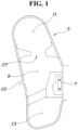
FIG. 1 is a view showing a structure of a seat airbag according to the present invention; -
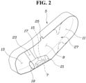
FIG. 2 is a view showing an internal structure of the seat airbag inFIG. 1 by partially cutting the seat airbag; -
FIG. 3 is a view showing a flow of an inflating gas of the seat airbag inFIG. 1 ; and -
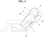
FIG. 4 is an example view showing a status of the seat airbag inFIG. 1 mounted to a seat. - Hereinbelow, a preferred embodiment described in the specification will be described in detail with reference to accompanying drawings, and regardless of the reference numerals, the same reference numerals will refer to the same or like parts, and redundant descriptions thereof will be omitted.
- The suffixes "module and "part" for the components used in the following description are given or mixed in consideration of only the ease of writing the specification, and do not have distinct meanings or roles by themselves.
- In the following description, if it is decided that the detailed description of known function or configuration related to the invention makes the subject matter of the invention unclear, the detailed description is omitted. Furthermore, the accompanying drawings are only for understanding of the preferred embodiments of the present invention, and the technical ideas disclosed in the specification are not limited by the accompanying drawings, and those skilled in the art will appreciate that various modifications, additions and substitutions are possible, without departing from the scope and spirit of the invention as disclosed in the accompanying claims.
- It will be understood that, although the terms first and/or second, etc. may be used herein to describe various elements, these elements should not be limited by these terms. These terms are only used to distinguish one element, from another element.
- It is to be understood that when one element is referred to as being "connected to" or "coupled to" another element, it may be connected directly to or coupled directly to another element or be connected to or coupled to another element, having the other element intervening therebetween. On the other hand, it is to be understood that when one element is referred to as being "connected directly to" or "coupled directly to" another element, it may be connected to or coupled to another element without the other element intervening therebetween.
- Singular forms are intended to include plural forms unless the context clearly indicates otherwise.
- It will be further understood that the terms "comprises" or "have" used in this specification, specify the presence of stated features, steps, operations, components, parts, or a combination thereof, but do not preclude the presence or addition of one or more other features, numerals, steps, operations, components, parts, or a combination thereof.
- Furthermore, a unit or a control unit included in names such as a motor control unit (MCU), a hybrid control unit (HCU), etc. is only a widely used term for a controller that controls a specific function of a vehicle, and does not mean a generic function unit.
- The controller may include a communication device communicating with other controllers or a sensor to control the function in charge, a memory storing an operation system or a logic command and input/output information, and at least one process performing determination, calculation, and decision necessary for controlling the function in charge.
- Referring to
FIGS. 1 to 4 , according to an embodiment of the present invention, a seat airbag includes acushion part 5 mounted to aseatback 3 of aseat 1, and including at least two chambers connected or accessible to each other in a vertical direction of theseatback 3; and aninflator 7 supplying an inflating gas to thecushion part 5. - The
cushion part 5 includes: abase chamber 9 provided to protect the chest and stomach of a passenger; anupper chamber 11 connected to an upper portion of thebase chamber 9 and provided to protect the head of the passenger; and alower chamber 13 provided to protect the pelvis of the passenger and provided at a lower portion of thebase chamber 9. - In other words, when the cushion part is mounted to the
seatback 3 and theseatback 3 is tilted in forward and rearward directions of the seat, thecushion part 5 mounted to theseatback 3 and moving together with theseatback 3 includes, with thebase chamber 9 as the center, theupper chamber 11 at the upper side of thebase chamber 9 and thelower chamber 13 at the lower side of thebase chamber 9. Even in a reclined state of the seat, in an event such as a side collision of a vehicle, theupper chamber 11 may protect the passenger's head, thelower chamber 13 may protect the passenger's pelvis, and thebase chamber 9 may protect the passenger's chest and stomach. - Therefore, with the seat airbag of the present invention, without a separate curtain airbag or a separate side airbag, the passenger's pelvis, chest, stomach, and head can be protected from an impact applied from the side of the vehicle in all available status of the
seatback 3. - The
inflator 7 is disposed to discharge the inflating gas in a direction; from thebase chamber 9 of thecushion part 5 to thelower chamber 13. - Therefore, in the
cushion part 5, thelower chamber 13 inflates first. Since a vehicle portion where an impact penetrates the indoor space and the indoor space is reduced is a portion where the passenger's pelvis in an event of a side collision of the vehicle, and considering the location, thelower chamber 13 inflates first to protect the passenger's pelvis. - The
inflator 7 is provided inside adiffuser pocket 17 in thecushion part 5 with thediffuser 15; and thediffuser pocket 17 includes alower hole 19 open toward thelower chamber 13 and anupper hole 21 open toward thebase chamber 9. - Furthermore, the
base chamber 9 and thelower chamber 13 are partitioned by apartition membrane 23 connected to thediffuser pocket 17. - Therefore, the inflating gas discharged from the
inflator 7 to thelower hole 19 of thediffuser pocket 17 passes through thelower chamber 13 as shown inFIG. 3 , and then passes again through thediffuser pocket 17 to inflate thebase chamber 9 at the upper side. - Of course, since the
diffuser pocket 17 includes theupper hole 21, some of the gas discharged from theinflator 7 may be directly supplied into thebase chamber 9 through theupper hole 21 without passing through thelower chamber 13. - As described above, the inflating gas supplied into the
base chamber 9 is transferred to theupper chamber 11 so that theupper chamber 11 inflates, and some of the inflating gas is discharged to the outside space of the cushion part through avent hole 25 so as to absorb an impact generated due to contact between the passenger and the airbag. - At this point, the
vent hole 25 through which the inflating gas supplied from theinflator 7 is discharged to the outside space is formed only in thebase chamber 9, so that it is possible to achieve impact-absorbing of the passenger as described above, and to allow theupper chamber 11 and thelower chamber 13 that need relatively stronger supporting force to maintain proper inflating pressure. - A volume of the
upper chamber 11 is formed smaller than a volume of thebase chamber 9. Furthermore, a volume of thelower chamber 13 is formed smaller than the volume of the base chamber. - Therefore, as described above, the
upper chamber 11 and thelower chamber 13 can support respectively the passenger's head and pelvis by relatively higher pressure compared to thebase chamber 9. - At least one
communication path 27 is provided between theupper chamber 11 and thebase chamber 9, and the at least onecommunication path 27 is formed by a media forming a thickness less than the maximum thickness of theupper chamber 11 and thebase chamber 9 or a non-inflating area. - Therefore, the inflating gas of the
base chamber 9 is supplied to theupper chamber 11 through thecommunication path 27, so that theupper chamber 11 inflates. - At this point, the minimum diameter of the
communication path 27 is formed larger than a diameter of thevent hole 25 so as to allow precise and rapid inflation of theupper chamber 11 to be performed. - A conventional tether, etc. may be used as the media, and the non-inflating area may be provided by preventing, for example, a portion marked by an alternated long and short dash line as shown in
FIG. 2 from inflating by in a sewing or bonding manner. - In the embodiment, the
base chamber 9 and thelower chamber 13 of thecushion part 5 are partitioned from each other by thediffuser pocket 17, which accommodates theinflator 7 therein and allows thebase chamber 9 and thelower chamber 13 to communicate with each other, and thepartition membrane 23 connected to thediffuser pocket 17; and the portion with thediffuser pocket 17 of thecushion part 5 is fixed to a side portion of theseatback 3 of theseat 1. - Therefore, as shown in
FIG. 4 , even when theseatback 3 is tilted rearward to be in an inclined status, thecushion part 5 has a rearward inclined status together with theseatback 3, so that in an event of a side collision of the vehicle, the stomach and chest of the passenger in the reclinedseat 1, as well as the passenger's head and pelvis, can be protected. - The seat airbag of the present invention configured as described above may be described as follows.
- In other words, the seat airbag of an embodiment of the present invention includes: the
cushion part 5 including thebase chamber 9 configured to inflate from the side portion of theseatback 3 of theseat 1 toward the front side of theseatback 3, and theupper chamber 11 configured to inflate upward from thebase chamber 9 by the inflating gas supplied from thebase chamber 9; and theinflator 7 configured to supply the inflating gas to thecushion part 5. - The
cushion part 5 includes thelower chamber 13 inflating downward from thebase chamber 9; and thelower chamber 13 inflates to a position where the passenger's pelvis on theseat 1 is protectable against a side impact of theseat 1 by being surrounded by thelower chamber 13; and theupper chamber 11 is configured to inflate to a position where the passenger's head on theseat 1 is protectable against the side impact of theseat 1 by being surrounded by the upper chamber. - The
base chamber 9, theupper chamber 11, and thelower chamber 13 are configured to communicate with each other; and thebase chamber 9 and thelower chamber 13 are configured to communicate with each other through thediffuser pocket 17 accommodating theinflator 7 therein. - The
diffuser pocket 17 has theupper hole 21 communicating with thebase chamber 9 and thelower hole 19 communicating with thelower chamber 13; theinflator 7 is disposed to discharge the inflating gas toward thelower hole 19; and an outer portion of thediffuser pocket 17 is connected to a partition wall partitioning thebase chamber 9 and thelower chamber 13 from each other. - The
base chamber 9 has thevent hole 25 discharging the inflating gas discharged from theinflator 7 to the outside space of thecushion part 5. - The at least one
communication path 27 formed by the media or the non-inflating area may be provided between theupper chamber 11 and thebase chamber 9, and the minimum diameter of thecommunication path 27 may be formed larger than a diameter of thevent hole 25. - Furthermore, both the volume of the
upper chamber 11 and the volume of thelower chamber 13 may be formed smaller than the volume of thebase chamber 9. - Although the preferred embodiment of the present invention has been disclosed in detail only with respect to the above specific embodiment, those skilled in the art will appreciate that various modifications, additions, and substitutions are possible, without departing from the spirit and scope of the present invention, and it is appropriate that the various modifications, additions, and substitutions belong to the accompanying claims.
Claims (15)
- A seat airbag comprising:a cushion part mounted to a seatback of a seat, and comprising at least two chambers accessible to each other in a vertical direction of the seatback; andan inflator provided to supply an inflating gas to the cushion part.
- The seat airbag of claim 1, wherein the cushion part comprises:a base chamber provided to protect a chest and stomach of a passenger; andan upper chamber connected to an upper portion of the base chamber to protect a head of the passenger.
- The seat airbag of claim 2, wherein the cushion part comprises a lower chamber provided below the base chamber to protect a pelvis of the passenger.
- The seat airbag of claim 3, wherein the inflator is disposed to discharge the inflating gas from the base chamber of the cushion part toward the lower chamber.
- The seat airbag of claim 4, wherein the inflator is provided together with a diffuser in a diffuser pocket, the diffuser pocket being within the cushion part; and
the diffuser pocket has a lower hole open toward the lower chamber and an upper hole open toward the base chamber. - The seat airbag of claim 5, wherein the base chamber and the lower chamber are partitioned by a partition membrane connected to the diffuser pocket.
- The seat airbag of any one of claims 4 to 6, wherein at least one communication path is provided between the upper chamber and the base chamber, the at least one communication path being formed (1) by a media having a thickness less than a maximum thickness of the upper chamber and the base chamber, or (2) by a non-inflating area.
- The seat airbag of claim 7, wherein a vent hole formed only in the base chamber is configured to discharge the inflating gas supplied from the inflator outward; and
the minimum diameter of the communication path is larger than a diameter of the vent hole. - The seat airbag of any one of claims 4 to 8, wherein the base chamber and the lower chamber of the cushion part are partitioned from each other by (1) a diffuser pocket accommodating the inflator therein and communicating the base chamber to the lower chamber, and (2) a partition membrane connected to the diffuser pocket; and
a portion of the cushion part with the diffuser pocket is fixed to a side portion of the seatback of the seat. - A seat airbag comprising:a cushion part comprising a base chamber provided at a side portion of a seatback of a seat and configured to inflate toward a front space of the seatback, and an upper chamber configured to inflate upward on the base chamber by an inflating gas supplied from the base chamber; andan inflator configured to supply the inflating gas to the cushion part.
- The seat airbag of claim 10, wherein:the cushion part further comprises a lower chamber configured to inflate downward below the base chamber;the lower chamber is configured to inflate to a position where a pelvis of a passenger in the seat is protectable against a side impact of the seat by being surrounded by the lower chamber; andthe upper chamber is configured to inflate to a position where a head of the passenger in the seat is protectable against a side impact of the seat by being surrounded by the upper chamber.
- The seat airbag of claim 11, wherein the base chamber, the upper chamber, and the lower chamber are configured to communicate with each other; and
the base chamber and the lower chamber are configured to communicate with each other via a diffuser pocket accommodating the inflator therein. - The seat airbag of claim 12, wherein:the diffuser pocket has an upper hole communicating with the base chamber and a lower hole communicating with the lower chamber;the inflator is disposed to discharge the inflating gas toward the lower hole; andan outer portion of the diffuser pocket is connected to a partition wall partitioning the base chamber and the lower chamber from each other.
- The seat airbag of claim 13, wherein the base chamber has a vent hole arranged to discharge the inflating gas discharged from the inflator to an outside space of the cushion part.
- The seat airbag of claim 14, wherein at least one communication path is provided between the upper chamber and the base chamber, and the at least one communication path is formed by a media or a non-inflating area.
Applications Claiming Priority (1)
| Application Number | Priority Date | Filing Date | Title |
|---|---|---|---|
| KR1020220093266A KR102464301B1 (en) | 2022-07-27 | 2022-07-27 | Seat airbag |
Publications (2)
| Publication Number | Publication Date |
|---|---|
| EP4311731A1 true EP4311731A1 (en) | 2024-01-31 |
| EP4311731B1 EP4311731B1 (en) | 2025-02-19 |
Family
ID=84537024
Family Applications (1)
| Application Number | Title | Priority Date | Filing Date |
|---|---|---|---|
| EP22213708.5A Active EP4311731B1 (en) | 2022-07-27 | 2022-12-15 | Seat airbag |
Country Status (4)
| Country | Link |
|---|---|
| US (1) | US11820314B1 (en) |
| EP (1) | EP4311731B1 (en) |
| KR (1) | KR102464301B1 (en) |
| CN (1) | CN117465378A (en) |
Citations (6)
| Publication number | Priority date | Publication date | Assignee | Title |
|---|---|---|---|---|
| US6062594A (en) * | 1997-02-27 | 2000-05-16 | Toyoda Gosei Co., Ltd. | Air bag for protecting passenger from side collision which has uniform inflation characteristics |
| US20040130127A1 (en) * | 2003-01-03 | 2004-07-08 | Takata Corporation | Airbag system |
| US20090184500A1 (en) * | 2006-07-11 | 2009-07-23 | Takata-Petri Ag | Airbag arrangement |
| EP3275738A1 (en) * | 2015-03-23 | 2018-01-31 | Autoliv Development AB | Air bag device |
| US20210122318A1 (en) * | 2019-10-23 | 2021-04-29 | Hyundai Motor Company | Side airbag for vehicle |
| US20210402946A1 (en) * | 2020-06-24 | 2021-12-30 | Hyundai Mobis Co., Ltd. | Side air bag apparatus for vehicle |
Family Cites Families (13)
| Publication number | Priority date | Publication date | Assignee | Title |
|---|---|---|---|---|
| US6270113B1 (en) * | 1998-10-06 | 2001-08-07 | Breed Automotive Technology, Inc. | Side air bag system |
| JP4566629B2 (en) * | 2004-06-28 | 2010-10-20 | マツダ株式会社 | Airbag device |
| JP5433250B2 (en) * | 2009-02-13 | 2014-03-05 | 芦森工業株式会社 | Airbag device |
| KR101509780B1 (en) | 2009-07-31 | 2015-04-08 | 현대자동차주식회사 | Automobile side air bag unit |
| JP2011126413A (en) * | 2009-12-17 | 2011-06-30 | Toyota Motor Corp | Side airbag device attached to seat |
| JP5803948B2 (en) * | 2013-01-23 | 2015-11-04 | トヨタ自動車株式会社 | Side airbag device for vehicle |
| JP6018313B2 (en) * | 2013-08-06 | 2016-11-02 | オートリブ ディベロップメント エービー | Side airbag device for vehicle |
| US11518339B2 (en) * | 2016-12-26 | 2022-12-06 | Autoliv Development Ab | Side air bag device |
| KR102373411B1 (en) * | 2019-06-04 | 2022-03-14 | 현대자동차주식회사 | Seat airbag for vehicle |
| US11383670B2 (en) * | 2019-09-30 | 2022-07-12 | Toyoda Gosei Co., Ltd. | Side airbag apparatus |
| KR102810811B1 (en) * | 2020-01-30 | 2025-05-20 | 현대모비스 주식회사 | Side airbag of vehicle and operating method of the same |
| KR102416588B1 (en) * | 2020-03-17 | 2022-07-05 | 현대자동차주식회사 | Seat airbag for vehicle |
| KR102928634B1 (en) * | 2021-01-18 | 2026-02-19 | 현대모비스 주식회사 | Side air bag |
-
2022
- 2022-07-27 KR KR1020220093266A patent/KR102464301B1/en active Active
- 2022-12-12 US US18/079,096 patent/US11820314B1/en active Active
- 2022-12-15 EP EP22213708.5A patent/EP4311731B1/en active Active
- 2022-12-16 CN CN202211637431.XA patent/CN117465378A/en active Pending
Patent Citations (6)
| Publication number | Priority date | Publication date | Assignee | Title |
|---|---|---|---|---|
| US6062594A (en) * | 1997-02-27 | 2000-05-16 | Toyoda Gosei Co., Ltd. | Air bag for protecting passenger from side collision which has uniform inflation characteristics |
| US20040130127A1 (en) * | 2003-01-03 | 2004-07-08 | Takata Corporation | Airbag system |
| US20090184500A1 (en) * | 2006-07-11 | 2009-07-23 | Takata-Petri Ag | Airbag arrangement |
| EP3275738A1 (en) * | 2015-03-23 | 2018-01-31 | Autoliv Development AB | Air bag device |
| US20210122318A1 (en) * | 2019-10-23 | 2021-04-29 | Hyundai Motor Company | Side airbag for vehicle |
| US20210402946A1 (en) * | 2020-06-24 | 2021-12-30 | Hyundai Mobis Co., Ltd. | Side air bag apparatus for vehicle |
Also Published As
| Publication number | Publication date |
|---|---|
| US11820314B1 (en) | 2023-11-21 |
| KR20240015417A (en) | 2024-02-05 |
| KR102464301B1 (en) | 2024-10-24 |
| EP4311731B1 (en) | 2025-02-19 |
| CN117465378A (en) | 2024-01-30 |
Similar Documents
| Publication | Publication Date | Title |
|---|---|---|
| US11351949B2 (en) | Roof-mounted occupant restraint system | |
| US9707922B2 (en) | Airbag module | |
| US11117540B2 (en) | Roof airbag apparatus | |
| US10696265B2 (en) | Curtain airbag system of vehicle | |
| JP5177220B2 (en) | Air bag device between seats for vehicles | |
| US11299123B2 (en) | Front airbag device for vehicle | |
| JP5831634B2 (en) | Side airbag device for vehicle | |
| JP5664607B2 (en) | Side airbag device for vehicle | |
| KR20190042202A (en) | Variable control apparatus for airbag of vehicle | |
| EP3978322A1 (en) | Side airbag device and method for manufacturing side airbag device | |
| CN113329916B (en) | Safety airbag device for driver's seat | |
| WO2021138388A1 (en) | Airbag module | |
| US12233810B2 (en) | Occupant protection device | |
| CN112292290A (en) | Side airbag device and vehicle seat provided with same | |
| EP3744579B1 (en) | Side air bag device and vehicle seat with same | |
| US11299121B2 (en) | Automotive side airbag and method of operating same | |
| EP4311731B1 (en) | Seat airbag | |
| KR20240168100A (en) | Control system and method for deploying the airbag | |
| JP4229887B2 (en) | Side airbag device | |
| KR102416668B1 (en) | Driver airbag apparatus of vehicle | |
| JP6709148B2 (en) | Airbag | |
| KR20220139183A (en) | Side airbag apparatus for vehicle | |
| JP4078632B2 (en) | Side airbag device and its deployment method | |
| US12365300B2 (en) | Seatbelt airbag | |
| US12397735B2 (en) | Airbag apparatus |
Legal Events
| Date | Code | Title | Description |
|---|---|---|---|
| PUAI | Public reference made under article 153(3) epc to a published international application that has entered the european phase |
Free format text: ORIGINAL CODE: 0009012 |
|
| STAA | Information on the status of an ep patent application or granted ep patent |
Free format text: STATUS: REQUEST FOR EXAMINATION WAS MADE |
|
| 17P | Request for examination filed |
Effective date: 20230114 |
|
| AK | Designated contracting states |
Kind code of ref document: A1 Designated state(s): AL AT BE BG CH CY CZ DE DK EE ES FI FR GB GR HR HU IE IS IT LI LT LU LV MC ME MK MT NL NO PL PT RO RS SE SI SK SM TR |
|
| RBV | Designated contracting states (corrected) |
Designated state(s): AL AT BE BG CH CY CZ DE DK EE ES FI FR GB GR HR HU IE IS IT LI LT LU LV MC ME MK MT NL NO PL PT RO RS SE SI SK SM TR |
|
| GRAP | Despatch of communication of intention to grant a patent |
Free format text: ORIGINAL CODE: EPIDOSNIGR1 |
|
| STAA | Information on the status of an ep patent application or granted ep patent |
Free format text: STATUS: GRANT OF PATENT IS INTENDED |
|
| RIC1 | Information provided on ipc code assigned before grant |
Ipc: B60R 21/231 20110101ALI20240830BHEP Ipc: B60R 21/207 20060101AFI20240830BHEP |
|
| INTG | Intention to grant announced |
Effective date: 20240916 |
|
| GRAS | Grant fee paid |
Free format text: ORIGINAL CODE: EPIDOSNIGR3 |
|
| GRAA | (expected) grant |
Free format text: ORIGINAL CODE: 0009210 |
|
| STAA | Information on the status of an ep patent application or granted ep patent |
Free format text: STATUS: THE PATENT HAS BEEN GRANTED |
|
| AK | Designated contracting states |
Kind code of ref document: B1 Designated state(s): AL AT BE BG CH CY CZ DE DK EE ES FI FR GB GR HR HU IE IS IT LI LT LU LV MC ME MK MT NL NO PL PT RO RS SE SI SK SM TR |
|
| P01 | Opt-out of the competence of the unified patent court (upc) registered |
Free format text: CASE NUMBER: APP_1958/2025 Effective date: 20250113 |
|
| REG | Reference to a national code |
Ref country code: GB Ref legal event code: FG4D |
|
| REG | Reference to a national code |
Ref country code: CH Ref legal event code: EP |
|
| REG | Reference to a national code |
Ref country code: DE Ref legal event code: R096 Ref document number: 602022010800 Country of ref document: DE |
|
| REG | Reference to a national code |
Ref country code: IE Ref legal event code: FG4D |
|
| REG | Reference to a national code |
Ref country code: NL Ref legal event code: MP Effective date: 20250219 |
|
| PG25 | Lapsed in a contracting state [announced via postgrant information from national office to epo] |
Ref country code: RS Free format text: LAPSE BECAUSE OF FAILURE TO SUBMIT A TRANSLATION OF THE DESCRIPTION OR TO PAY THE FEE WITHIN THE PRESCRIBED TIME-LIMIT Effective date: 20250519 |
|
| PG25 | Lapsed in a contracting state [announced via postgrant information from national office to epo] |
Ref country code: FI Free format text: LAPSE BECAUSE OF FAILURE TO SUBMIT A TRANSLATION OF THE DESCRIPTION OR TO PAY THE FEE WITHIN THE PRESCRIBED TIME-LIMIT Effective date: 20250219 |
|
| PG25 | Lapsed in a contracting state [announced via postgrant information from national office to epo] |
Ref country code: PL Free format text: LAPSE BECAUSE OF FAILURE TO SUBMIT A TRANSLATION OF THE DESCRIPTION OR TO PAY THE FEE WITHIN THE PRESCRIBED TIME-LIMIT Effective date: 20250219 |
|
| PG25 | Lapsed in a contracting state [announced via postgrant information from national office to epo] |
Ref country code: ES Free format text: LAPSE BECAUSE OF FAILURE TO SUBMIT A TRANSLATION OF THE DESCRIPTION OR TO PAY THE FEE WITHIN THE PRESCRIBED TIME-LIMIT Effective date: 20250219 |
|
| REG | Reference to a national code |
Ref country code: LT Ref legal event code: MG9D |
|
| PG25 | Lapsed in a contracting state [announced via postgrant information from national office to epo] |
Ref country code: IS Free format text: LAPSE BECAUSE OF FAILURE TO SUBMIT A TRANSLATION OF THE DESCRIPTION OR TO PAY THE FEE WITHIN THE PRESCRIBED TIME-LIMIT Effective date: 20250619 Ref country code: NO Free format text: LAPSE BECAUSE OF FAILURE TO SUBMIT A TRANSLATION OF THE DESCRIPTION OR TO PAY THE FEE WITHIN THE PRESCRIBED TIME-LIMIT Effective date: 20250519 |
|
| PG25 | Lapsed in a contracting state [announced via postgrant information from national office to epo] |
Ref country code: NL Free format text: LAPSE BECAUSE OF FAILURE TO SUBMIT A TRANSLATION OF THE DESCRIPTION OR TO PAY THE FEE WITHIN THE PRESCRIBED TIME-LIMIT Effective date: 20250219 |
|
| PG25 | Lapsed in a contracting state [announced via postgrant information from national office to epo] |
Ref country code: HR Free format text: LAPSE BECAUSE OF FAILURE TO SUBMIT A TRANSLATION OF THE DESCRIPTION OR TO PAY THE FEE WITHIN THE PRESCRIBED TIME-LIMIT Effective date: 20250219 |
|
| PG25 | Lapsed in a contracting state [announced via postgrant information from national office to epo] |
Ref country code: PT Free format text: LAPSE BECAUSE OF FAILURE TO SUBMIT A TRANSLATION OF THE DESCRIPTION OR TO PAY THE FEE WITHIN THE PRESCRIBED TIME-LIMIT Effective date: 20250620 Ref country code: LV Free format text: LAPSE BECAUSE OF FAILURE TO SUBMIT A TRANSLATION OF THE DESCRIPTION OR TO PAY THE FEE WITHIN THE PRESCRIBED TIME-LIMIT Effective date: 20250219 |
|
| PG25 | Lapsed in a contracting state [announced via postgrant information from national office to epo] |
Ref country code: BG Free format text: LAPSE BECAUSE OF FAILURE TO SUBMIT A TRANSLATION OF THE DESCRIPTION OR TO PAY THE FEE WITHIN THE PRESCRIBED TIME-LIMIT Effective date: 20250219 Ref country code: GR Free format text: LAPSE BECAUSE OF FAILURE TO SUBMIT A TRANSLATION OF THE DESCRIPTION OR TO PAY THE FEE WITHIN THE PRESCRIBED TIME-LIMIT Effective date: 20250520 |
|
| REG | Reference to a national code |
Ref country code: AT Ref legal event code: MK05 Ref document number: 1768024 Country of ref document: AT Kind code of ref document: T Effective date: 20250219 |
|
| PG25 | Lapsed in a contracting state [announced via postgrant information from national office to epo] |
Ref country code: SE Free format text: LAPSE BECAUSE OF FAILURE TO SUBMIT A TRANSLATION OF THE DESCRIPTION OR TO PAY THE FEE WITHIN THE PRESCRIBED TIME-LIMIT Effective date: 20250219 |
|
| PG25 | Lapsed in a contracting state [announced via postgrant information from national office to epo] |
Ref country code: SM Free format text: LAPSE BECAUSE OF FAILURE TO SUBMIT A TRANSLATION OF THE DESCRIPTION OR TO PAY THE FEE WITHIN THE PRESCRIBED TIME-LIMIT Effective date: 20250219 |
|
| PG25 | Lapsed in a contracting state [announced via postgrant information from national office to epo] |
Ref country code: DK Free format text: LAPSE BECAUSE OF FAILURE TO SUBMIT A TRANSLATION OF THE DESCRIPTION OR TO PAY THE FEE WITHIN THE PRESCRIBED TIME-LIMIT Effective date: 20250219 |
|
| PG25 | Lapsed in a contracting state [announced via postgrant information from national office to epo] |
Ref country code: IT Free format text: LAPSE BECAUSE OF FAILURE TO SUBMIT A TRANSLATION OF THE DESCRIPTION OR TO PAY THE FEE WITHIN THE PRESCRIBED TIME-LIMIT Effective date: 20250219 |
|
| PG25 | Lapsed in a contracting state [announced via postgrant information from national office to epo] |
Ref country code: AT Free format text: LAPSE BECAUSE OF FAILURE TO SUBMIT A TRANSLATION OF THE DESCRIPTION OR TO PAY THE FEE WITHIN THE PRESCRIBED TIME-LIMIT Effective date: 20250219 |
|
| PG25 | Lapsed in a contracting state [announced via postgrant information from national office to epo] |
Ref country code: EE Free format text: LAPSE BECAUSE OF FAILURE TO SUBMIT A TRANSLATION OF THE DESCRIPTION OR TO PAY THE FEE WITHIN THE PRESCRIBED TIME-LIMIT Effective date: 20250219 Ref country code: CZ Free format text: LAPSE BECAUSE OF FAILURE TO SUBMIT A TRANSLATION OF THE DESCRIPTION OR TO PAY THE FEE WITHIN THE PRESCRIBED TIME-LIMIT Effective date: 20250219 |
|
| PG25 | Lapsed in a contracting state [announced via postgrant information from national office to epo] |
Ref country code: RO Free format text: LAPSE BECAUSE OF FAILURE TO SUBMIT A TRANSLATION OF THE DESCRIPTION OR TO PAY THE FEE WITHIN THE PRESCRIBED TIME-LIMIT Effective date: 20250219 |
|
| PG25 | Lapsed in a contracting state [announced via postgrant information from national office to epo] |
Ref country code: SK Free format text: LAPSE BECAUSE OF FAILURE TO SUBMIT A TRANSLATION OF THE DESCRIPTION OR TO PAY THE FEE WITHIN THE PRESCRIBED TIME-LIMIT Effective date: 20250219 |
|
| REG | Reference to a national code |
Ref country code: DE Ref legal event code: R097 Ref document number: 602022010800 Country of ref document: DE |
|
| PLBE | No opposition filed within time limit |
Free format text: ORIGINAL CODE: 0009261 |
|
| STAA | Information on the status of an ep patent application or granted ep patent |
Free format text: STATUS: NO OPPOSITION FILED WITHIN TIME LIMIT |
|
| REG | Reference to a national code |
Ref country code: CH Ref legal event code: L10 Free format text: ST27 STATUS EVENT CODE: U-0-0-L10-L00 (AS PROVIDED BY THE NATIONAL OFFICE) Effective date: 20251231 |
|
| PGFP | Annual fee paid to national office [announced via postgrant information from national office to epo] |
Ref country code: DE Payment date: 20251020 Year of fee payment: 4 |
|
| PGFP | Annual fee paid to national office [announced via postgrant information from national office to epo] |
Ref country code: FR Payment date: 20251021 Year of fee payment: 4 |
|
| 26N | No opposition filed |
Effective date: 20251120 |
|
| PG25 | Lapsed in a contracting state [announced via postgrant information from national office to epo] |
Ref country code: LT Free format text: LAPSE BECAUSE OF FAILURE TO SUBMIT A TRANSLATION OF THE DESCRIPTION OR TO PAY THE FEE WITHIN THE PRESCRIBED TIME-LIMIT Effective date: 20250219 |
|
| PG25 | Lapsed in a contracting state [announced via postgrant information from national office to epo] |
Ref country code: MC Free format text: LAPSE BECAUSE OF FAILURE TO SUBMIT A TRANSLATION OF THE DESCRIPTION OR TO PAY THE FEE WITHIN THE PRESCRIBED TIME-LIMIT Effective date: 20250219 |
|
| REG | Reference to a national code |
Ref country code: CH Ref legal event code: H13 Free format text: ST27 STATUS EVENT CODE: U-0-0-H10-H13 (AS PROVIDED BY THE NATIONAL OFFICE) Effective date: 20260723 |