EP4311719A1 - Vehicle thermal runaway warning method, device, electronic equipment and readable storage medium - Google Patents
Vehicle thermal runaway warning method, device, electronic equipment and readable storage medium Download PDFInfo
- Publication number
- EP4311719A1 EP4311719A1 EP23186078.4A EP23186078A EP4311719A1 EP 4311719 A1 EP4311719 A1 EP 4311719A1 EP 23186078 A EP23186078 A EP 23186078A EP 4311719 A1 EP4311719 A1 EP 4311719A1
- Authority
- EP
- European Patent Office
- Prior art keywords
- voltage
- vehicle
- subinterval
- cell voltage
- thermal runaway
- Prior art date
- Legal status (The legal status is an assumption and is not a legal conclusion. Google has not performed a legal analysis and makes no representation as to the accuracy of the status listed.)
- Granted
Links
Images

Classifications
-
- G—PHYSICS
- G01—MEASURING; TESTING
- G01R—MEASURING ELECTRIC VARIABLES; MEASURING MAGNETIC VARIABLES
- G01R31/00—Arrangements for testing electric properties; Arrangements for locating electric faults; Arrangements for electrical testing characterised by what is being tested not provided for elsewhere
- G01R31/36—Arrangements for testing, measuring or monitoring the electrical condition of accumulators or electric batteries, e.g. capacity or state of charge [SoC]
- G01R31/396—Acquisition or processing of data for testing or for monitoring individual cells or groups of cells within a battery
-
- B—PERFORMING OPERATIONS; TRANSPORTING
- B60—VEHICLES IN GENERAL
- B60L—PROPULSION OF ELECTRICALLY-PROPELLED VEHICLES; SUPPLYING ELECTRIC POWER FOR AUXILIARY EQUIPMENT OF ELECTRICALLY-PROPELLED VEHICLES; ELECTRODYNAMIC BRAKE SYSTEMS FOR VEHICLES IN GENERAL; MAGNETIC SUSPENSION OR LEVITATION FOR VEHICLES; MONITORING OPERATING VARIABLES OF ELECTRICALLY-PROPELLED VEHICLES; ELECTRIC SAFETY DEVICES FOR ELECTRICALLY-PROPELLED VEHICLES
- B60L3/00—Electric devices on electrically-propelled vehicles for safety purposes; Monitoring operating variables, e.g. speed, deceleration or energy consumption
- B60L3/0023—Detecting, eliminating, remedying or compensating for drive train abnormalities, e.g. failures within the drive train
- B60L3/0046—Detecting, eliminating, remedying or compensating for drive train abnormalities, e.g. failures within the drive train relating to electric energy storage systems, e.g. batteries or capacitors
-
- B—PERFORMING OPERATIONS; TRANSPORTING
- B60—VEHICLES IN GENERAL
- B60L—PROPULSION OF ELECTRICALLY-PROPELLED VEHICLES; SUPPLYING ELECTRIC POWER FOR AUXILIARY EQUIPMENT OF ELECTRICALLY-PROPELLED VEHICLES; ELECTRODYNAMIC BRAKE SYSTEMS FOR VEHICLES IN GENERAL; MAGNETIC SUSPENSION OR LEVITATION FOR VEHICLES; MONITORING OPERATING VARIABLES OF ELECTRICALLY-PROPELLED VEHICLES; ELECTRIC SAFETY DEVICES FOR ELECTRICALLY-PROPELLED VEHICLES
- B60L58/00—Methods or circuit arrangements for monitoring or controlling batteries or fuel cells, specially adapted for electric vehicles
- B60L58/10—Methods or circuit arrangements for monitoring or controlling batteries or fuel cells, specially adapted for electric vehicles for monitoring or controlling batteries
-
- B—PERFORMING OPERATIONS; TRANSPORTING
- B60—VEHICLES IN GENERAL
- B60L—PROPULSION OF ELECTRICALLY-PROPELLED VEHICLES; SUPPLYING ELECTRIC POWER FOR AUXILIARY EQUIPMENT OF ELECTRICALLY-PROPELLED VEHICLES; ELECTRODYNAMIC BRAKE SYSTEMS FOR VEHICLES IN GENERAL; MAGNETIC SUSPENSION OR LEVITATION FOR VEHICLES; MONITORING OPERATING VARIABLES OF ELECTRICALLY-PROPELLED VEHICLES; ELECTRIC SAFETY DEVICES FOR ELECTRICALLY-PROPELLED VEHICLES
- B60L58/00—Methods or circuit arrangements for monitoring or controlling batteries or fuel cells, specially adapted for electric vehicles
- B60L58/10—Methods or circuit arrangements for monitoring or controlling batteries or fuel cells, specially adapted for electric vehicles for monitoring or controlling batteries
- B60L58/16—Methods or circuit arrangements for monitoring or controlling batteries or fuel cells, specially adapted for electric vehicles for monitoring or controlling batteries responding to battery ageing, e.g. to the number of charging cycles or the state of health [SoH]
-
- G—PHYSICS
- G01—MEASURING; TESTING
- G01R—MEASURING ELECTRIC VARIABLES; MEASURING MAGNETIC VARIABLES
- G01R31/00—Arrangements for testing electric properties; Arrangements for locating electric faults; Arrangements for electrical testing characterised by what is being tested not provided for elsewhere
- G01R31/36—Arrangements for testing, measuring or monitoring the electrical condition of accumulators or electric batteries, e.g. capacity or state of charge [SoC]
- G01R31/392—Determining battery ageing or deterioration, e.g. state of health
-
- H—ELECTRICITY
- H01—ELECTRIC ELEMENTS
- H01M—PROCESSES OR MEANS, e.g. BATTERIES, FOR THE DIRECT CONVERSION OF CHEMICAL ENERGY INTO ELECTRICAL ENERGY
- H01M10/00—Secondary cells; Manufacture thereof
- H01M10/42—Methods or arrangements for servicing or maintenance of secondary cells or secondary half-cells
-
- H—ELECTRICITY
- H01—ELECTRIC ELEMENTS
- H01M—PROCESSES OR MEANS, e.g. BATTERIES, FOR THE DIRECT CONVERSION OF CHEMICAL ENERGY INTO ELECTRICAL ENERGY
- H01M10/00—Secondary cells; Manufacture thereof
- H01M10/42—Methods or arrangements for servicing or maintenance of secondary cells or secondary half-cells
- H01M10/4207—Methods or arrangements for servicing or maintenance of secondary cells or secondary half-cells for several batteries or cells simultaneously or sequentially
-
- H—ELECTRICITY
- H01—ELECTRIC ELEMENTS
- H01M—PROCESSES OR MEANS, e.g. BATTERIES, FOR THE DIRECT CONVERSION OF CHEMICAL ENERGY INTO ELECTRICAL ENERGY
- H01M10/00—Secondary cells; Manufacture thereof
- H01M10/42—Methods or arrangements for servicing or maintenance of secondary cells or secondary half-cells
- H01M10/425—Structural combination with electronic components, e.g. electronic circuits integrated to the outside of the casing
-
- H—ELECTRICITY
- H01—ELECTRIC ELEMENTS
- H01M—PROCESSES OR MEANS, e.g. BATTERIES, FOR THE DIRECT CONVERSION OF CHEMICAL ENERGY INTO ELECTRICAL ENERGY
- H01M10/00—Secondary cells; Manufacture thereof
- H01M10/42—Methods or arrangements for servicing or maintenance of secondary cells or secondary half-cells
- H01M10/48—Accumulators combined with arrangements for measuring, testing or indicating the condition of cells, e.g. the level or density of the electrolyte
-
- H—ELECTRICITY
- H01—ELECTRIC ELEMENTS
- H01M—PROCESSES OR MEANS, e.g. BATTERIES, FOR THE DIRECT CONVERSION OF CHEMICAL ENERGY INTO ELECTRICAL ENERGY
- H01M10/00—Secondary cells; Manufacture thereof
- H01M10/42—Methods or arrangements for servicing or maintenance of secondary cells or secondary half-cells
- H01M10/48—Accumulators combined with arrangements for measuring, testing or indicating the condition of cells, e.g. the level or density of the electrolyte
- H01M10/482—Accumulators combined with arrangements for measuring, testing or indicating the condition of cells, e.g. the level or density of the electrolyte for several batteries or cells simultaneously or sequentially
-
- H—ELECTRICITY
- H01—ELECTRIC ELEMENTS
- H01M—PROCESSES OR MEANS, e.g. BATTERIES, FOR THE DIRECT CONVERSION OF CHEMICAL ENERGY INTO ELECTRICAL ENERGY
- H01M10/00—Secondary cells; Manufacture thereof
- H01M10/42—Methods or arrangements for servicing or maintenance of secondary cells or secondary half-cells
- H01M10/48—Accumulators combined with arrangements for measuring, testing or indicating the condition of cells, e.g. the level or density of the electrolyte
- H01M10/486—Accumulators combined with arrangements for measuring, testing or indicating the condition of cells, e.g. the level or density of the electrolyte for measuring temperature
-
- B—PERFORMING OPERATIONS; TRANSPORTING
- B60—VEHICLES IN GENERAL
- B60L—PROPULSION OF ELECTRICALLY-PROPELLED VEHICLES; SUPPLYING ELECTRIC POWER FOR AUXILIARY EQUIPMENT OF ELECTRICALLY-PROPELLED VEHICLES; ELECTRODYNAMIC BRAKE SYSTEMS FOR VEHICLES IN GENERAL; MAGNETIC SUSPENSION OR LEVITATION FOR VEHICLES; MONITORING OPERATING VARIABLES OF ELECTRICALLY-PROPELLED VEHICLES; ELECTRIC SAFETY DEVICES FOR ELECTRICALLY-PROPELLED VEHICLES
- B60L2240/00—Control parameters of input or output; Target parameters
- B60L2240/40—Drive Train control parameters
- B60L2240/54—Drive Train control parameters related to batteries
- B60L2240/545—Temperature
-
- B—PERFORMING OPERATIONS; TRANSPORTING
- B60—VEHICLES IN GENERAL
- B60L—PROPULSION OF ELECTRICALLY-PROPELLED VEHICLES; SUPPLYING ELECTRIC POWER FOR AUXILIARY EQUIPMENT OF ELECTRICALLY-PROPELLED VEHICLES; ELECTRODYNAMIC BRAKE SYSTEMS FOR VEHICLES IN GENERAL; MAGNETIC SUSPENSION OR LEVITATION FOR VEHICLES; MONITORING OPERATING VARIABLES OF ELECTRICALLY-PROPELLED VEHICLES; ELECTRIC SAFETY DEVICES FOR ELECTRICALLY-PROPELLED VEHICLES
- B60L2240/00—Control parameters of input or output; Target parameters
- B60L2240/40—Drive Train control parameters
- B60L2240/54—Drive Train control parameters related to batteries
- B60L2240/547—Voltage
-
- B—PERFORMING OPERATIONS; TRANSPORTING
- B60—VEHICLES IN GENERAL
- B60L—PROPULSION OF ELECTRICALLY-PROPELLED VEHICLES; SUPPLYING ELECTRIC POWER FOR AUXILIARY EQUIPMENT OF ELECTRICALLY-PROPELLED VEHICLES; ELECTRODYNAMIC BRAKE SYSTEMS FOR VEHICLES IN GENERAL; MAGNETIC SUSPENSION OR LEVITATION FOR VEHICLES; MONITORING OPERATING VARIABLES OF ELECTRICALLY-PROPELLED VEHICLES; ELECTRIC SAFETY DEVICES FOR ELECTRICALLY-PROPELLED VEHICLES
- B60L2240/00—Control parameters of input or output; Target parameters
- B60L2240/80—Time limits
-
- B—PERFORMING OPERATIONS; TRANSPORTING
- B60—VEHICLES IN GENERAL
- B60L—PROPULSION OF ELECTRICALLY-PROPELLED VEHICLES; SUPPLYING ELECTRIC POWER FOR AUXILIARY EQUIPMENT OF ELECTRICALLY-PROPELLED VEHICLES; ELECTRODYNAMIC BRAKE SYSTEMS FOR VEHICLES IN GENERAL; MAGNETIC SUSPENSION OR LEVITATION FOR VEHICLES; MONITORING OPERATING VARIABLES OF ELECTRICALLY-PROPELLED VEHICLES; ELECTRIC SAFETY DEVICES FOR ELECTRICALLY-PROPELLED VEHICLES
- B60L2250/00—Driver interactions
- B60L2250/10—Driver interactions by alarm
-
- B—PERFORMING OPERATIONS; TRANSPORTING
- B60—VEHICLES IN GENERAL
- B60Y—INDEXING SCHEME RELATING TO ASPECTS CROSS-CUTTING VEHICLE TECHNOLOGY
- B60Y2200/00—Type of vehicle
- B60Y2200/90—Vehicles comprising electric prime movers
- B60Y2200/91—Electric vehicles
-
- B—PERFORMING OPERATIONS; TRANSPORTING
- B60—VEHICLES IN GENERAL
- B60Y—INDEXING SCHEME RELATING TO ASPECTS CROSS-CUTTING VEHICLE TECHNOLOGY
- B60Y2400/00—Special features of vehicle units
- B60Y2400/11—Electric energy storages
- B60Y2400/112—Batteries
-
- B—PERFORMING OPERATIONS; TRANSPORTING
- B60—VEHICLES IN GENERAL
- B60Y—INDEXING SCHEME RELATING TO ASPECTS CROSS-CUTTING VEHICLE TECHNOLOGY
- B60Y2400/00—Special features of vehicle units
- B60Y2400/90—Driver alarms
-
- H—ELECTRICITY
- H01—ELECTRIC ELEMENTS
- H01M—PROCESSES OR MEANS, e.g. BATTERIES, FOR THE DIRECT CONVERSION OF CHEMICAL ENERGY INTO ELECTRICAL ENERGY
- H01M10/00—Secondary cells; Manufacture thereof
- H01M10/42—Methods or arrangements for servicing or maintenance of secondary cells or secondary half-cells
- H01M10/425—Structural combination with electronic components, e.g. electronic circuits integrated to the outside of the casing
- H01M2010/4271—Battery management systems including electronic circuits, e.g. control of current or voltage to keep battery in healthy state, cell balancing
-
- H—ELECTRICITY
- H01—ELECTRIC ELEMENTS
- H01M—PROCESSES OR MEANS, e.g. BATTERIES, FOR THE DIRECT CONVERSION OF CHEMICAL ENERGY INTO ELECTRICAL ENERGY
- H01M2220/00—Batteries for particular applications
- H01M2220/20—Batteries in motive systems, e.g. vehicle, ship, plane
-
- Y—GENERAL TAGGING OF NEW TECHNOLOGICAL DEVELOPMENTS; GENERAL TAGGING OF CROSS-SECTIONAL TECHNOLOGIES SPANNING OVER SEVERAL SECTIONS OF THE IPC; TECHNICAL SUBJECTS COVERED BY FORMER USPC CROSS-REFERENCE ART COLLECTIONS [XRACs] AND DIGESTS
- Y02—TECHNOLOGIES OR APPLICATIONS FOR MITIGATION OR ADAPTATION AGAINST CLIMATE CHANGE
- Y02T—CLIMATE CHANGE MITIGATION TECHNOLOGIES RELATED TO TRANSPORTATION
- Y02T10/00—Road transport of goods or passengers
- Y02T10/60—Other road transportation technologies with climate change mitigation effect
- Y02T10/70—Energy storage systems for electromobility, e.g. batteries
Definitions
- the present application relates to the technical field of electric vehicles, in particular to a vehicle thermal runaway warning method, device, electronic equipment and readable storage medium.
- the method for detecting the thermal runaway risk is usually to obtain parameters such as temperature, voltage, current and discharge rate of the battery body. Since the thermal runaway phenomenon generally spreads from a single cell to the entire battery, only detecting the risk of vehicle thermal runaway based on the overall parameters of the battery will make the timeliness of the thermal runaway risk warning low, so that the user cannot replace the battery in time, and the risk of vehicle thermal runaway is still high.
- the main purpose of the present application is to provide a vehicle thermal runaway warning method, device, electronic equipment and readable storage medium, aiming to solve the technical problem of high risk of vehicle thermal runaway in the related art.
- the present application provides a vehicle thermal runaway warning method, applied to a vehicle thermal runaway warning device.
- the vehicle thermal runaway warning method includes:
- the method further includes:
- the cell voltage characteristic includes a first characteristic value and a second characteristic value
- the method before in response to that each cell voltage characteristic meets the preset voltage warning condition, determining that the vehicle has the risk of thermal runaway, and controlling the vehicle to output the thermal runaway warning information, the method further includes:
- the determining the first voltage deviation value of the high voltage subinterval and the second voltage deviation value of the low voltage subinterval in the partial cell voltage data corresponding to each of the time windows includes:
- the obtaining the first voltage mean value difference of the high voltage subinterval and the second voltage mean value difference of the low voltage subinterval in the partial cell voltage data corresponding to each of the time windows includes:
- the obtaining the first voltage deviation degree of the high voltage subinterval and the second voltage deviation degree of the low voltage subinterval includes:
- the present application further provides a vehicle thermal runaway warning device, applied to a vehicle thermal runaway warning apparatus, including
- the vehicle thermal runaway warning device is further configured for:
- the cell voltage characteristic includes a first characteristic value and a second characteristic value
- the vehicle thermal runaway warning device before the operation of in response to that each cell voltage characteristic meets the preset voltage warning condition, determining that the vehicle has the risk of thermal runaway, and controlling the vehicle to output the thermal runaway warning information, the vehicle thermal runaway warning device is further configured for:
- the extracting module is further configured for:
- the extracting module is further configured for:
- the extracting module is further configured for:
- the present application further provides an electronic equipment, including: a memory, a processor, and a vehicle thermal runaway warning program stored in the memory and executable by the processor.
- vehicle thermal runaway warning program stored in the memory and executable by the processor.
- the present application further provides a computer-readable storage medium.
- the computer-readable storage medium stores a program for realizing a vehicle thermal runaway warning method, when the vehicle thermal runaway warning program is executed by a processor, the operations of the vehicle thermal runaway warning method as described above are realized.
- the present application further provides a computer program product, including a computer program.
- a computer program product including a computer program.
- the computer program is executed by a processor, the operations of the above-mentioned vehicle thermal runaway warning method are realized.
- the present application provides a vehicle thermal runaway warning method, device, electronic equipment and readable storage medium.
- the method includes: obtaining operating data of a vehicle, the operating data being a plurality of cell voltage data of a battery pack in the vehicle; dividing time windows for the plurality of cell voltage data according to a collection timing of the operating data, and extracting cell voltage characteristics from a partial cell voltage data corresponding to each of the divided time windows; and in response to that each cell voltage characteristic meets a preset voltage warning condition, determining that the vehicle has a risk of thermal runaway, and controlling the vehicle to output thermal runaway warning information.
- the thermal runaway risk of the vehicle is determined according to the cell voltage characteristic, then the thermal runaway risk of the vehicle is warned, and the thermal runaway risk of the vehicle is determined according to the voltage characteristic change trend of the battery cell voltage.
- the thermal runaway warning information is input to prompt the user to replace the battery, thereby avoiding the thermal runaway phenomenon of the vehicle, reducing the thermal runaway risk of the vehicle and improving the safety of the vehicle.
- Embodiments of the present application provide a vehicle thermal runaway warning method.
- the vehicle thermal runaway warning method includes:
- the operating data being a plurality of cell voltage data of a battery pack in the vehicle; dividing time windows for the plurality of cell voltage data according to a collection timing of the operating data, and extracting cell voltage characteristics from a partial cell voltage data corresponding to each of the divided time windows; and in response to that each cell voltage characteristic meets a preset voltage warning condition, determining that the vehicle has a risk of thermal runaway, and controlling the vehicle to output thermal runaway warning information.
- the thermal runaway risk of the electric vehicle is detected, so as to give early warning to remind users to replace the battery pack to avoid thermal runaway.
- the method for detecting the thermal runaway risk is usually to obtain parameters such as temperature, voltage, current and discharge rate of the battery body. Since the thermal runaway phenomenon generally spreads from a single cell to the entire battery, only detecting the risk of vehicle thermal runaway based on the overall parameters of the battery will make the timeliness of the thermal runaway risk warning low, so that the user cannot replace the battery in time, and the risk of vehicle thermal runaway is still high.
- the thermal runaway risk of the vehicle is determined according to the cell voltage characteristic, then the thermal runaway risk of the vehicle is warned, and the thermal runaway risk of the vehicle is determined according to the voltage characteristic change trend of the battery cell voltage.
- the thermal runaway warning information is input to prompt the user to replace the battery, thereby avoiding the thermal runaway phenomenon of the vehicle, reducing the thermal runaway risk of the vehicle and improving the safety of the vehicle.
- the vehicle thermal runaway warning method includes following operations.
- Operation S10 obtaining operating data of a vehicle, the operating data being a plurality of cell voltage data of a battery pack in the vehicle.
- the vehicle thermal runaway warning method of the present application can be applied to the vehicle or to the control system in the vehicle, and can also be applied to the server communicated with the vehicle.
- the communication connection can be a wired connection such as an interface, or a wireless connection such as Bluetooth or a local area network, so as to realize interactive processing of data and predict the thermal runaway risk of the vehicle.
- the above-mentioned vehicle is used as the execution subject of the vehicle thermal runaway warning method of the present application to describe this embodiment in detail.
- the operating data of the vehicle is the cell voltage data of the battery pack in the vehicle obtained at preset time intervals.
- the preset time interval is the preset interval time for collecting the operating data of the vehicle.
- the preset time interval can be 5s or 10s.
- the preset time interval can be randomly selected by the control system of the vehicle and/or the vehicle, or can be set by the user.
- the vehicle obtains the operating data of the vehicle.
- the vehicle obtains the operating data of the vehicle from the pressure sensor built in the battery pack through reception.
- Operation S20 dividing time windows for the plurality of cell voltage data according to a collection timing of the operating data, and extracting cell voltage characteristics from a partial cell voltage data corresponding to each of the divided time windows.
- the time window division is performed on the operating data of the vehicle.
- the number of preset window data is the preset number of window data in each time window data.
- the number of preset window data is a number divisible by the number of operating data of the vehicle, and the number of preset window data may be 20,000 or 15,000. For example, when the number of operating data of the vehicle is 60,000 and the number of preset window data is 20,000, the number of time window data is 3.
- the operating data of the vehicle is divided into 3 time window data in chronological order, or the start and end time of each time window are obtained based on the product of the preset time interval and the number of preset window data.
- the time window division is performed on the operating data of the vehicle. For example, when the preset time interval is 10s and the number of preset window data is 6, the start and end time of the first time window data is 0s to 60s, and the start and end time of the second time window data is 60s to 120s.
- the method further includes: obtaining a voltage range of the battery pack in the vehicle.
- the voltage range is composed of the maximum voltage value and the minimum voltage value of the battery pack in the vehicle, and the voltage range is determined by the battery characteristics of the battery pack in the vehicle. Battery characteristics include battery model and battery performance, and the voltage range can be 3.5V to 4.2V
- the battery model and the battery performance of the battery pack in the vehicle are obtained, and the voltage range of the battery pack is obtained according to the battery model and the battery performance. constructing a voltage interval corresponding to the operating data of the vehicle according to the voltage range and a preset voltage interval range, the voltage interval including at least one voltage subinterval.
- the preset voltage range is the preset interval voltage of each voltage range, and the preset voltage range may be 0.05V or 0.1V.
- each voltage interval corresponding to the operating data of the vehicle is constructed.
- the first voltage subinterval is (3.5-3.6)
- the second voltage subinterval is (3.6-3.7)
- the third voltage subinterval is (3.7-3.8)
- nth voltage subinterval is (4.1-4.2). dividing the partial cell voltage data corresponding to each of the time windows into corresponding voltage subinterval.
- the voltage median of the partial cell voltage data corresponding to each time window is obtained as the cell voltage value at each time window.
- the cell voltage value of each partial cell voltage data is divided into corresponding voltage subintervals. For example, when the median voltage of the cell voltage data from the 0th to the 1st time window in the first time window is 3.57V, the cell voltage value from the 0th to the 1st time window in the first time window is 3.57V, which is divided into the first voltage subinterval (3.5-3.6).
- FIG. 2 includes: time window data (time window 1, time window 2, ..., time window n, and data frame 1, data frame ... shown in the figure), voltage subinterval (voltage interval 1, voltage interval 2, ..., voltage interval 14 shown in the figure).
- the cell voltage characteristic includes a first characteristic value and a second characteristic value
- the extracting the cell voltage characteristics from the partial cell voltage data corresponding to each of the divided time windows includes:
- Operation S21 selecting a high voltage subinterval and a corresponding low voltage subinterval corresponding to the partial cell voltage data in each of the voltage subintervals.
- the high voltage subinterval and the corresponding low voltage subinterval corresponding to the partial cell voltage data of the preset voltage interval are selected.
- the number of preset voltage intervals is 2, the two intervals with the lowest voltage range of each voltage subinterval are regarded as low voltage subintervals, and the two intervals with the highest voltage range of each voltage subinterval are regarded as high voltage subintervals.
- the two intervals with the lowest voltage ranges of each voltage subinterval are averaged to obtain the low voltage subinterval, and the two intervals with the highest voltage ranges of each voltage subinterval are averaged to obtain the high voltage subinterval.
- Operation S22 determining a first voltage deviation value of the high voltage subinterval and a second voltage deviation value of the low voltage subinterval in the partial cell voltage data corresponding to each of the time windows according to each partial cell voltage data.
- Operation S23 using a voltage deviation difference between the first voltage deviation value and the second voltage deviation value as the first characteristic value, and using the second voltage deviation value as the second characteristic value.
- the voltage deviation difference between each first voltage deviation value and each second voltage deviation value of the partial cell voltage data corresponding to each time window is taken as the first characteristic value
- each second voltage deviation value is taken as the second characteristic value
- the first characteristic value and the second characteristic value are integrated to obtain cell voltage characteristics corresponding to the partial cell voltage data in each time window.
- the method before in response to that each cell voltage characteristic meets the preset voltage warning condition, determining that the vehicle has the risk of thermal runaway, and controlling the vehicle to output the thermal runaway warning information, the method further includes:
- Operation A10 determining whether the first characteristic value is greater than a preset characteristic threshold and whether a first discrete degree of the first characteristic value meets a preset first discrete degree, and determining whether the second discrete degree of the second characteristic value meets a preset second discrete degree.
- Operation A20 in response to that the first characteristic value is greater than the preset characteristic threshold, the first discrete degree meets the preset first discrete degree, and the second discrete degree meets the preset second discrete degree, determining that the cell voltage characteristic meets the preset voltage warning condition.
- the preset characteristic threshold is a preset first characteristic critical value for determining that the voltage deviation difference between the first voltage deviation value of the high voltage subinterval and the second voltage deviation value of the low voltage subinterval is too small.
- the preset characteristic threshold can be 0.00001 or 0.00002.
- the preset first discrete degree is the predetermined discrete degree of the voltage deviation difference between the first voltage deviation value of the high voltage subinterval and the second voltage deviation value of the low voltage subinterval for determining that the vehicle may have a risk of thermal runaway.
- the preset first discrete degree may be 4 ⁇ .
- the preset second discrete degree is the predetermined discrete degree of the second voltage deviation value in the low voltage subinterval for determining that the vehicle may have a risk of thermal runaway, and the preset second discrete degree may be 1 ⁇ .
- the preset voltage warning condition is a preset cell voltage characteristic condition that the vehicle may have a risk of thermal runaway.
- the first characteristic value is greater than the preset characteristic threshold value, it means that there is a cell voltage in the battery pack of the vehicle that may be overheated.
- the first discrete degree meets the preset first discrete degree, and the second discrete degree meets the preset second discrete degree, it means that there are multiple cell voltages in the battery pack of the vehicle that are overheated, that is, there is a risk of thermal runaway of the vehicle.
- the first discrete degree of the first characteristic value and the second discrete degree of the second characteristic value are obtained, whether the first characteristic value is greater than the preset characteristic threshold and whether the first discrete degree meets the preset first discrete degree is determined, and whether the second discrete degree meets the preset second discrete degree is determined. If the first characteristic value is greater than the preset characteristic threshold, the first discrete degree meets the preset first discrete degree, and the second discrete degree meets the preset second discrete degree, it is determined that the cell voltage characteristic meets the preset voltage warning conditions.
- the first characteristic value is not greater than the preset characteristic threshold, and/or, the first discrete degree does not meet the preset first discrete degree, and/or, the second discrete degree does not meet the preset second discrete degree, it is determined that the cell voltage characteristic does not meet the preset voltage warning conditions.
- Operation S30 in response to that each cell voltage characteristic meets a preset voltage warning condition, determining that the vehicle has a risk of thermal runaway, and controlling the vehicle to output thermal runaway warning information.
- the thermal runaway warning information is used to warn the user that the vehicle has a risk of thermal runaway, so that the user can replace the battery.
- the content of the thermal runaway warning information may be text display content, voice broadcast content, or a combination of text display content and voice broadcast content.
- each cell voltage characteristic meets the preset voltage warning condition. If each cell voltage characteristic meets the preset voltage warning condition, it is determined that the vehicle has a risk of thermal runaway, and the vehicle is controlled to output thermal runaway warning information. If some cell voltage characteristics do not meet the preset voltage warning conditions, it is determined that the vehicle does not have a risk of thermal runaway, and return to perform the operation: extracting the cell voltage characteristics from the partial cell voltage data corresponding to each of the divided time windows.
- the operation of controlling the vehicle to output thermal runaway warning information may include: controlling the on-board screen of the vehicle to display thermal runaway warning information, and/or controlling the sound broadcast module of the vehicle to broadcast thermal runaway warning information.
- the internal resistance of each cell in the battery pack of the vehicle is calculated through the equivalent circuit model, and the risk of thermal runaway of the vehicle is determined according to the change of internal resistance of each cell, so as to control the vehicle to output thermal runaway warning information, thereby avoiding the risk of thermal runaway. Since the operating conditions of the real vehicle are not static, the risk of thermal runaway of the vehicle is determined only by the change of the internal resistance of the battery pack, without considering other factors, and it is easy to determine the risk of thermal runaway inaccurately.
- the accuracy of the thermal runaway alarm of the vehicle is low (for example, the thermal runaway alarm is performed when the vehicle does not have the risk of thermal runaway, or the thermal runaway alarm cannot be performed in time when the vehicle has the risk of thermal runaway).
- the risk of thermal runaway of the vehicle is determined to control the vehicle to output thermal runaway warning information, thereby avoiding the risk of thermal runaway.
- this method can only capture the early features of the vehicle when the safety fault has occurred, and give a safety fault alarm, and the time reserved for the user to replace the battery is short, resulting in a high risk of thermal runaway of the vehicle.
- Obtaining the above features requires built-in sensors and the sensors usually require regular maintenance, which increases the cost of detecting the risk of thermal runaway of the vehicle.
- the preset voltage warning condition is the empirical value of the voltage characteristic warning obtained from the operating data of a large number of vehicles with thermal runaway phenomena.
- the risk of thermal runaway of the vehicle is determined on the voltage characteristic change trend of the cell voltage of the battery.
- the thermal runaway warning information is input to prompt the user to replace the battery, thereby avoiding the thermal runaway phenomenon of the vehicle, and reducing the risk of the thermal runaway phenomenon of the vehicle.
- the present application provides a vehicle thermal runaway warning method, device, electronic equipment and readable storage medium.
- the method includes: obtaining operating data of a vehicle, the operating data being a plurality of cell voltage data of a battery pack in the vehicle; dividing time windows for the plurality of cell voltage data according to a collection timing of the operating data, and extracting cell voltage characteristics from a partial cell voltage data corresponding to each of the divided time windows; and in response to that each cell voltage characteristic meets a preset voltage warning condition, determining that the vehicle has a risk of thermal runaway, and controlling the vehicle to output thermal runaway warning information.
- the thermal runaway risk of the vehicle is determined according to the cell voltage characteristic, then the thermal runaway risk of the vehicle is warned, and the thermal runaway risk of the vehicle is determined according to the voltage characteristic change trend of the battery cell voltage.
- the thermal runaway warning information is input to prompt the user to replace the battery, thereby avoiding the thermal runaway phenomenon of the vehicle, reducing the thermal runaway risk of the vehicle and improving the safety of the vehicle.
- the present application provides a second embodiment of the vehicle thermal runaway warning method.
- the vehicle thermal runaway warning method is also implemented by the aforementioned vehicle as the execution subject.
- the operation of determining the first voltage deviation value of the high voltage subinterval and the second voltage deviation value of the low voltage subinterval in the partial cell voltage data corresponding to each of the time windows may include:
- Operation B10 obtaining a first voltage mean value difference of the high voltage subinterval and a second voltage mean value difference of the low voltage subinterval in the partial cell voltage data corresponding to each of the time windows.
- the voltage mean value difference is configured to represent the values of the voltage subintervals of some cell voltage data in each time window.
- the first voltage mean value difference of the high voltage subinterval and the second voltage mean value difference of the low voltage subinterval of the partial cell voltage data in each of the time windows are calculated according to the partial cell voltage data.
- the operation of obtaining the first voltage mean value difference of the high voltage subinterval and the second voltage mean value difference of the low voltage subinterval in the partial cell voltage data corresponding to each of the time windows may include:
- Operation B11 using the partial cell voltage data corresponding to a first time window as an initial window data.
- the partial cell voltage data corresponding to the first time window is used as the initial window data, for example, the partial cell voltage data of the first time window is used as the initial window data.
- Operation B 12 obtaining a first cell voltage value of the high voltage subinterval in the initial window data, a second cell voltage value of the high voltage subinterval in the partial cell voltage data corresponding to each of the time windows, a third cell voltage value of the low voltage subinterval in the initial window data and a fourth cell voltage value of the low voltage subinterval in the partial cell voltage data corresponding to each of the time windows.
- the average value of the cell voltage of the high voltage subinterval in the initial window data is acquired to obtain the first cell voltage value of the high voltage subinterval.
- the average value of the cell voltage of the high voltage subinterval in the partial cell voltage data corresponding to each time window is acquired to obtain the second cell voltage value of the high voltage subinterval.
- the average value of the cell voltage of the low voltage subinterval in the initial window data is acquired to obtain the third cell voltage value of the low voltage subinterval.
- the average value of the cell voltage of the low voltage subinterval in the partial cell voltage data corresponding to each time window is acquired to obtain the fourth cell voltage value of the low voltage subinterval.
- Operation B 13 using a first voltage difference between the first cell voltage value and the second cell voltage value as a first voltage mean value difference of the high voltage subinterval, and using a second voltage difference between the third cell voltage value and the fourth cell voltage value as a second voltage mean value difference of the low voltage subinterval.
- the first voltage difference between the first cell voltage value and the second cell voltage value is calculated as the first voltage mean value difference of the high voltage subinterval
- the second voltage difference between the third cell voltage value and the fourth cell voltage value is calculated as the second voltage mean value difference of the low voltage subinterval
- Operation B20 obtaining a first voltage deviation degree of the high voltage subinterval and a second voltage deviation degree of the low voltage subinterval.
- the first voltage deviation degree of the high voltage subinterval is calculated according to the first voltage mean value difFerence, the first cell voltage value and the third cell voltage value.
- the second voltage deviation degree of the low voltage subinterval is calculated according to the second average voltage difFerence, the second cell voltage value and the fourth cell voltage value.
- the operation of obtaining the first voltage deviation degree of the high voltage subinterval and the second voltage deviation degree of the low voltage subinterval may include:
- Operation B21 obtaining a fifth cell voltage value of each cell voltage data in the high voltage subinterval, a sixth cell voltage value of each cell voltage data in the low voltage subinterval and a voltage median corresponding to each cell voltage data.
- the average cell voltage of each cell voltage value in the high voltage subinterval in the partial cell voltage data corresponding to each time window is acquired to obtain the fifth cell voltage value in the high voltage subinterval.
- the cell voltage mean value of each cell voltage value in the low voltage subinterval in the partial cell voltage data corresponding to each time window is acquired to obtain the sixth cell voltage value in the low voltage subinterval.
- the median of the average voltage values of each cell in the high voltage subinterval is acquired to obtain the first voltage median of the cell voltage values in the high voltage subinterval.
- the median of the average voltage values of each cell in the low voltage subinterval is acquired to obtain the first voltage median of the cell voltage values in the low voltage subinterval.
- Operation B22 obtaining a first voltage deviation degree of the high voltage subinterval according to the fifth cell voltage value and the corresponding median voltage, and obtaining a second voltage deviation degree of the low voltage subinterval according to the sixth cell voltage value and the corresponding median voltage.
- the first voltage deviation degree of the high voltage subinterval is determined according to the fifth cell voltage value, the first voltage median, and the voltage data amount of the high voltage subinterval.
- the second voltage deviation degree of the low voltage subinterval is determined according to the sixth cell voltage value, the second voltage median, and the voltage data amount of the low voltage subinterval.
- Operation B30 obtaining a first voltage deviation value of the high voltage subinterval according to a first product of the first voltage mean value difference and the first voltage deviation degree, and obtaining a second voltage deviation value of the low voltage subinterval according to a second product of the second voltage mean value difference and the second voltage deviation degree.
- the first product of the first voltage mean value difference and the first voltage deviation degree is calculated to obtain the first voltage deviation value of the high voltage subinterval.
- the second product of the second voltage mean value difference and the second voltage deviation degree is calculated to obtain the second voltage deviation value of the low voltage subinterval.
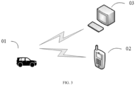
- FIG. 3 is a schematic diagram of an application scenario of the vehicle thermal runaway warning method provided by the present application.
- the application scenario may include: a vehicle 01, a control device 03 in communication with the vehicle 01, and a user equipment 02 in communication with the vehicle 01.
- the thermal runaway warning information is sent to the user equipment 02 corresponding to all users through the vehicle 01 to prompt the user to replace the vehicle battery pack.
- the thermal runaway warning information is sent to the control device 03 through the vehicle 01 to prompt the vehicle operation and maintenance personnel to replace the battery pack.
- the risk of thermal runaway of the vehicle can be determined by judging the preset voltage warning conditions for the cell voltage characteristics.
- the thermal runaway warning information is input to prompt the user to replace the battery, thereby avoiding the thermal runaway phenomenon of the vehicle, reducing the risk of thermal runaway of the vehicle and improving the safety of the vehicle.
- the embodiments of the present application further provide a vehicle as mentioned in any one of the above embodiments.
- FIG. 4 is a schematic structural diagram of a device of the hardware operating environment involved in the vehicle thermal runaway warning method of the present application.
- the vehicle may include: a processor 1001, such as a CPU, a communication bus 1002, a network interface 1003, and a memory 1004.
- the communication bus 1002 is configured to realize connection and communication between the processor 1001 and the memory 1004.
- the memory 1004 may be a high-speed RAM memory, or a stable memory (non-volatile memory), such as a disk memory.
- the memory 1004 may also be a storage device independent of the aforementioned processor 1001.
- the vehicle may further include a graphical user interface, a network interface, a camera, a radio frequency (RF) circuit, a sensor, an audio circuit, a WiFi module, and the like.
- the graphical user interface may include a display, an input sub-module such as a keyboard.
- the graphical user interface can also include a standard wired interface and a wireless interface.
- the network interface may also include a standard wired interface and a wireless interface (such as a WI-FI interface).
- the structure shown in FIG. 4 does not constitute a limitation on the vehicle. Based on different design requirements of actual applications, in different feasible implementation manners, the vehicle may also include more or fewer components than shown, or a combination of certain components, or difFerently arranged components.
- the memory 1004 as a storage medium may include an operating system, a network communication module, and a vehicle thermal runaway warning program.
- the operating system is a program that manages and controls resources based on vehicle hardware and software, and supports the operation of the vehicle thermal runaway warning program and other software and/or programs.
- the network communication module is configured to realize the communication among various components inside the memory 1004, and communicate with other hardware and software in the vehicle thermal runaway warning system.
- the processor 1001 is configured to execute the vehicle thermal runaway warning program stored in the memory 1004 to implement the operations of the vehicle thermal runaway warning method described in any of the above embodiments.
- the present application further provides a vehicle thermal runaway warning device.
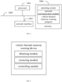
- the vehicle thermal runaway warning device is applied to the vehicle to control the vehicle thermal runaway warning, as shown in FIG. 5 , the vehicle thermal runaway warning device of the present application includes:
- the vehicle thermal runaway warning device is further configured for:
- the cell voltage characteristic includes a first characteristic value and a second characteristic value
- the vehicle thermal runaway warning device before the operation of in response to that each cell voltage characteristic meets the preset voltage warning condition, determining that the vehicle has the risk of thermal runaway, and controlling the vehicle to output the thermal runaway warning information, the vehicle thermal runaway warning device is further configured for:
- the extracting module is further configured for:
- the extracting module is further configured for:
- the extracting module is further configured for:
- each functional module of the vehicle thermal runaway warning device of the present application is basically the same as the above embodiments of the vehicle thermal runaway warning method, and will not be repeated herein.
- the embodiment of the present application provides a computer storage medium, and the computer storage medium stores one or more programs.
- the one or more programs can also be executed by one or more processors to implement the operations of the vehicle thermal runaway warning method described in any one of the above embodiments.
- the present application further provides a computer program product, including a computer program.
- a computer program product including a computer program.
- the computer program is executed by a processor, the operations of the above-mentioned vehicle thermal runaway warning method are realized.
- the technical solution of the present application can be embodied in the form of software product in essence or the part that contributes to the existing technology.
- the computer software product is stored on a storage medium (such as ROM/RAM, magnetic disk, optical disk) as described above, including several instructions to cause a terminal device (which can be a mobile phone, a computer, a server, an air conditioner, or a network device, etc.) to execute the method described in each embodiment of the present application.
Landscapes
- Engineering & Computer Science (AREA)
- Manufacturing & Machinery (AREA)
- General Chemical & Material Sciences (AREA)
- Electrochemistry (AREA)
- Chemical Kinetics & Catalysis (AREA)
- Chemical & Material Sciences (AREA)
- Power Engineering (AREA)
- Transportation (AREA)
- Mechanical Engineering (AREA)
- Sustainable Energy (AREA)
- Sustainable Development (AREA)
- Life Sciences & Earth Sciences (AREA)
- Physics & Mathematics (AREA)
- General Physics & Mathematics (AREA)
- Microelectronics & Electronic Packaging (AREA)
- Secondary Cells (AREA)
- Testing Electric Properties And Detecting Electric Faults (AREA)
- Charge And Discharge Circuits For Batteries Or The Like (AREA)
- Electric Propulsion And Braking For Vehicles (AREA)
- Time Recorders, Dirve Recorders, Access Control (AREA)
Abstract
Description
- The present application relates to the technical field of electric vehicles, in particular to a vehicle thermal runaway warning method, device, electronic equipment and readable storage medium.
- With the rapid development of electric vehicles, lithium batteries are widely used in electric vehicles due to their high voltage, high specific energy and long cycle life. When the electric vehicle fails, a large amount of heat energy will be released inside the battery, which is the thermal runaway phenomenon of the electric vehicle, and too much heat energy may cause the vehicle to catch fire or even explode. Therefore, it is particularly important to detect the thermal runaway risk of electric vehicles and provide early warning to remind users to replace the battery pack to avoid thermal runaway.
- Nowadays, the method for detecting the thermal runaway risk is usually to obtain parameters such as temperature, voltage, current and discharge rate of the battery body. Since the thermal runaway phenomenon generally spreads from a single cell to the entire battery, only detecting the risk of vehicle thermal runaway based on the overall parameters of the battery will make the timeliness of the thermal runaway risk warning low, so that the user cannot replace the battery in time, and the risk of vehicle thermal runaway is still high.
- The main purpose of the present application is to provide a vehicle thermal runaway warning method, device, electronic equipment and readable storage medium, aiming to solve the technical problem of high risk of vehicle thermal runaway in the related art.
- In order to achieve the above purpose, the present application provides a vehicle thermal runaway warning method, applied to a vehicle thermal runaway warning device. The vehicle thermal runaway warning method includes:
- obtaining operating data of a vehicle, the operating data being a plurality of cell voltage data of a battery pack in the vehicle;
- dividing time windows for the plurality of cell voltage data according to a collection timing of the operating data, and extracting cell voltage characteristics from a partial cell voltage data corresponding to each of the divided time windows; and
- in response to that each cell voltage characteristic meets a preset voltage warning condition, determining that the vehicle has a risk of thermal runaway, and controlling the vehicle to output thermal runaway warning information.
- In an embodiment, after dividing the time windows for the plurality of cell voltage data according to the collection timing of the operating data, the method further includes:
- obtaining a voltage range of the battery pack in the vehicle;
- constructing a voltage interval corresponding to the operating data of the vehicle according to the voltage range and a preset voltage interval range, the voltage interval including at least one voltage subinterval; and
- dividing the partial cell voltage data corresponding to each of the time windows into corresponding voltage subinterval.
- In an embodiment, the cell voltage characteristic includes a first characteristic value and a second characteristic value,
- the extracting the cell voltage characteristics from the partial cell voltage data corresponding to each of the divided time windows includes:
- selecting a high voltage subinterval and a corresponding low voltage subinterval corresponding to the partial cell voltage data in each of the voltage subintervals;
- determining a first voltage deviation value of the high voltage subinterval and a second voltage deviation value of the low voltage subinterval in the partial cell voltage data corresponding to each of the time windows; and
- using a voltage deviation difference between the first voltage deviation value and the second voltage deviation value as the first characteristic value, and using the second voltage deviation value as the second characteristic value.
- In an embodiment, before in response to that each cell voltage characteristic meets the preset voltage warning condition, determining that the vehicle has the risk of thermal runaway, and controlling the vehicle to output the thermal runaway warning information, the method further includes:
- determining whether the first characteristic value is greater than a preset characteristic threshold and whether a first discrete degree of the first characteristic value meets a preset first discrete degree, and determining whether the second discrete degree of the second characteristic value meets a preset second discrete degree; and
- in response to that the first characteristic value is greater than the preset characteristic threshold, the first discrete degree meets the preset first discrete degree, and the second discrete degree meets the preset second discrete degree, determining that the cell voltage characteristic meets the preset voltage warning condition.
- In an embodiment, the determining the first voltage deviation value of the high voltage subinterval and the second voltage deviation value of the low voltage subinterval in the partial cell voltage data corresponding to each of the time windows includes:
- obtaining a first voltage mean value difference of the high voltage subinterval and a second voltage mean value difference of the low voltage subinterval in the partial cell voltage data corresponding to each of the time windows;
- obtaining a first voltage deviation degree of the high voltage subinterval and a second voltage deviation degree of the low voltage subinterval; and
- obtaining a first voltage deviation value of the high voltage subinterval according to a first product of the first voltage mean value difference and the first voltage deviation degree, and obtaining a second voltage deviation value of the low voltage subinterval according to a second product of the second voltage mean value difference and the second voltage deviation degree.
- In an embodiment, the obtaining the first voltage mean value difference of the high voltage subinterval and the second voltage mean value difference of the low voltage subinterval in the partial cell voltage data corresponding to each of the time windows includes:
- using the partial cell voltage data corresponding to a first time window as an initial window data;
- obtaining a first cell voltage value of the high voltage subinterval in the initial window data, a second cell voltage value of the high voltage subinterval in the partial cell voltage data corresponding to each of the time windows, a third cell voltage value of the low voltage subinterval in the initial window data and a fourth cell voltage value of the low voltage subinterval in the partial cell voltage data corresponding to each of the time windows; and
- using a first voltage difference between the first cell voltage value and the second cell voltage value as a first voltage mean value difference of the high voltage subinterval, and using a second voltage difference between the third cell voltage value and the fourth cell voltage value as a second voltage mean value difference of the low voltage subinterval.
- In an embodiment, the obtaining the first voltage deviation degree of the high voltage subinterval and the second voltage deviation degree of the low voltage subinterval includes:
- obtaining a fifth cell voltage value of each cell voltage data in the high voltage subinterval, a sixth cell voltage value of each cell voltage data in the low voltage subinterval and a voltage median corresponding to each cell voltage data; and
- obtaining a first voltage deviation degree of the high voltage subinterval according to the fifth cell voltage value and the corresponding median voltage, and obtaining a second voltage deviation degree of the low voltage subinterval according to the sixth cell voltage value and the corresponding median voltage.
- In order to achieve the above objective, the present application further provides a vehicle thermal runaway warning device, applied to a vehicle thermal runaway warning apparatus, including
- an obtaining module configure for obtaining operating data of a vehicle, the operating data being a plurality of cell voltage data of a battery pack in the vehicle;
- an extracting module configured for dividing time windows for the plurality of cell voltage data according to a collection timing of the operating data, and extracting cell voltage characteristics from a partial cell voltage data corresponding to each of the divided time windows; and
- a controlling module configured for in response to that each cell voltage characteristic meets a preset voltage warning condition, determining that the vehicle has a risk of thermal runaway, and controlling the vehicle to output thermal runaway warning information.
- In an embodiment, after the operation of dividing the time windows for the plurality of cell voltage data according to the collection timing of the operating data, the vehicle thermal runaway warning device is further configured for:
- obtaining a voltage range of the battery pack in the vehicle;
- constructing a voltage interval corresponding to the operating data of the vehicle according to the voltage range and a preset voltage interval range, the voltage interval including at least one voltage subinterval; and
- dividing the partial cell voltage data corresponding to each of the time windows into corresponding voltage subinterval.
- In an embodiment, the cell voltage characteristic includes a first characteristic value and a second characteristic value,
- the extracting module is further configured for:
- selecting a high voltage subinterval and a corresponding low voltage subinterval corresponding to the partial cell voltage data in each of the voltage subintervals;
- determining a first voltage deviation value of the high voltage subinterval and a second voltage deviation value of the low voltage subinterval in the partial cell voltage data corresponding to each of the time windows; and
- using a voltage deviation difference between the first voltage deviation value and the second voltage deviation value as the first characteristic value, and using the second voltage deviation value as the second characteristic value.
- In an embodiment, before the operation of in response to that each cell voltage characteristic meets the preset voltage warning condition, determining that the vehicle has the risk of thermal runaway, and controlling the vehicle to output the thermal runaway warning information, the vehicle thermal runaway warning device is further configured for:
- determining whether the first characteristic value is greater than a preset characteristic threshold and whether a first discrete degree of the first characteristic value meets a preset first discrete degree, and determining whether the second discrete degree of the second characteristic value meets a preset second discrete degree; and
- in response to that the first characteristic value is greater than the preset characteristic threshold, the first discrete degree meets the preset first discrete degree, and the second discrete degree meets the preset second discrete degree, determining that the cell voltage characteristic meets the preset voltage warning condition.
- In an embodiment, the extracting module is further configured for:
- obtaining a first voltage mean value difference of the high voltage subinterval and a second voltage mean value difference of the low voltage subinterval in the partial cell voltage data corresponding to each of the time windows;
- obtaining a first voltage deviation degree of the high voltage subinterval and a second voltage deviation degree of the low voltage subinterval; and
- obtaining a first voltage deviation value of the high voltage subinterval according to a first product of the first voltage mean value difference and the first voltage deviation degree, and obtaining a second voltage deviation value of the low voltage subinterval according to a second product of the second voltage mean value difference and the second voltage deviation degree.
- In an embodiment, the extracting module is further configured for:
- using the partial cell voltage data corresponding to a first time window as an initial window data;
- obtaining a first cell voltage value of the high voltage subinterval in the initial window data, a second cell voltage value of the high voltage subinterval in the partial cell voltage data corresponding to each of the time windows, a third cell voltage value of the low voltage subinterval in the initial window data and a fourth cell voltage value of the low voltage subinterval in the partial cell voltage data corresponding to each of the time windows; and
- using a first voltage difference between the first cell voltage value and the second cell voltage value as a first voltage mean value difference of the high voltage subinterval, and using a second voltage difference between the third cell voltage value and the fourth cell voltage value as a second voltage mean value difference of the low voltage subinterval.
- In an embodiment, the extracting module is further configured for:
- obtaining a fifth cell voltage value of each cell voltage data in the high voltage subinterval, a sixth cell voltage value of each cell voltage data in the low voltage subinterval and a voltage median corresponding to each cell voltage data; and
- obtaining a first voltage deviation degree of the high voltage subinterval according to the fifth cell voltage value and the corresponding median voltage, and obtaining a second voltage deviation degree of the low voltage subinterval according to the sixth cell voltage value and the corresponding median voltage.
- The present application further provides an electronic equipment, including: a memory, a processor, and a vehicle thermal runaway warning program stored in the memory and executable by the processor. When the vehicle thermal runaway warning program is executed by the processor, the operations of the vehicle thermal runaway warning method as described above are realized.
- The present application further provides a computer-readable storage medium. The computer-readable storage medium stores a program for realizing a vehicle thermal runaway warning method, when the vehicle thermal runaway warning program is executed by a processor, the operations of the vehicle thermal runaway warning method as described above are realized.
- The present application further provides a computer program product, including a computer program. When the computer program is executed by a processor, the operations of the above-mentioned vehicle thermal runaway warning method are realized.
- The present application provides a vehicle thermal runaway warning method, device, electronic equipment and readable storage medium. The method includes: obtaining operating data of a vehicle, the operating data being a plurality of cell voltage data of a battery pack in the vehicle; dividing time windows for the plurality of cell voltage data according to a collection timing of the operating data, and extracting cell voltage characteristics from a partial cell voltage data corresponding to each of the divided time windows; and in response to that each cell voltage characteristic meets a preset voltage warning condition, determining that the vehicle has a risk of thermal runaway, and controlling the vehicle to output thermal runaway warning information.
- In the present application, by extracting the cell voltage characteristic of the cell voltage in the time series voltage data of the vehicle, the thermal runaway risk of the vehicle is determined according to the cell voltage characteristic, then the thermal runaway risk of the vehicle is warned, and the thermal runaway risk of the vehicle is determined according to the voltage characteristic change trend of the battery cell voltage. When the vehicle has a risk of thermal runaway, the thermal runaway warning information is input to prompt the user to replace the battery, thereby avoiding the thermal runaway phenomenon of the vehicle, reducing the thermal runaway risk of the vehicle and improving the safety of the vehicle.
- The accompanying drawings, which are incorporated in and constitute a part of this specification, illustrate embodiments consistent with the present application and together with the description serve to explain the principles of the present application.
- In order to more clearly illustrate the technical solutions in the embodiments of the present application or the prior art, the following will briefly introduce the drawings that need to be used in the embodiments of the present application or the prior art. Apparently, those skilled in the art can also obtain other drawings based on these drawings without any creative effort.
-
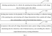
FIG. 1 is a schematic flowchart of a vehicle thermal runaway warning method according to a first embodiment of the present application. -
FIG. 2 is a schematic diagram of an application scenario of the vehicle thermal runaway warning method of the present application. -
FIG. 3 is a schematic diagram of another application scenario of the vehicle thermal runaway warning method of the present application. -
FIG. 4 is a schematic structural diagram of a device of the hardware operating environment involved in the vehicle thermal runaway warning method of the present application. -
FIG. 5 is a schematic structural diagram of a vehicle thermal runaway warning device according to an embodiment of the present application. - The realization of the objective, functional characteristics, and advantages of the present application are further described with reference to the accompanying drawings.
- In order to make the above objects, characteristics and advantages of the present application more obvious and understandable, the technical solutions in the embodiments of the present application will be clearly and completely described below in conjunction with the drawings in the embodiments of the present application. Apparently, the described embodiments are only some of the embodiments of the present application, not all of them. Based on the embodiments in the present application, all other embodiments obtained by persons of ordinary skill in the art without creative efforts shall fall within the scope of the present application.
- Embodiments of the present application provide a vehicle thermal runaway warning method. In a first embodiment of the present application, the vehicle thermal runaway warning method includes:
- obtaining operating data of a vehicle, the operating data being a plurality of cell voltage data of a battery pack in the vehicle; dividing time windows for the plurality of cell voltage data according to a collection timing of the operating data, and extracting cell voltage characteristics from a partial cell voltage data corresponding to each of the divided time windows; and in response to that each cell voltage characteristic meets a preset voltage warning condition, determining that the vehicle has a risk of thermal runaway, and controlling the vehicle to output thermal runaway warning information.
- It should be noted that, in this embodiment, in order to avoid thermal runaway of electric vehicles, the thermal runaway risk of the electric vehicle is detected, so as to give early warning to remind users to replace the battery pack to avoid thermal runaway. Nowadays, the method for detecting the thermal runaway risk is usually to obtain parameters such as temperature, voltage, current and discharge rate of the battery body. Since the thermal runaway phenomenon generally spreads from a single cell to the entire battery, only detecting the risk of vehicle thermal runaway based on the overall parameters of the battery will make the timeliness of the thermal runaway risk warning low, so that the user cannot replace the battery in time, and the risk of vehicle thermal runaway is still high.
- For the above phenomenon, in the present application, by extracting the cell voltage characteristic of the cell voltage in the time series voltage data of the vehicle, the thermal runaway risk of the vehicle is determined according to the cell voltage characteristic, then the thermal runaway risk of the vehicle is warned, and the thermal runaway risk of the vehicle is determined according to the voltage characteristic change trend of the battery cell voltage. When the vehicle has a risk of thermal runaway, the thermal runaway warning information is input to prompt the user to replace the battery, thereby avoiding the thermal runaway phenomenon of the vehicle, reducing the thermal runaway risk of the vehicle and improving the safety of the vehicle.
- As shown in
FIG. 1 , in the first embodiment of the present application, the vehicle thermal runaway warning method includes following operations. - Operation S10, obtaining operating data of a vehicle, the operating data being a plurality of cell voltage data of a battery pack in the vehicle.
- The vehicle thermal runaway warning method of the present application can be applied to the vehicle or to the control system in the vehicle, and can also be applied to the server communicated with the vehicle. The communication connection can be a wired connection such as an interface, or a wireless connection such as Bluetooth or a local area network, so as to realize interactive processing of data and predict the thermal runaway risk of the vehicle. For the convenience of reading and understanding, the above-mentioned vehicle is used as the execution subject of the vehicle thermal runaway warning method of the present application to describe this embodiment in detail.
- It should be noted that, in this embodiment, the operating data of the vehicle is the cell voltage data of the battery pack in the vehicle obtained at preset time intervals. The preset time interval is the preset interval time for collecting the operating data of the vehicle. The preset time interval can be 5s or 10s. The preset time interval can be randomly selected by the control system of the vehicle and/or the vehicle, or can be set by the user.
- In this embodiment, before the thermal runaway phenomenon occurs in the vehicle, the vehicle obtains the operating data of the vehicle.
- In this embodiment, the vehicle obtains the operating data of the vehicle from the pressure sensor built in the battery pack through reception.
- Operation S20, dividing time windows for the plurality of cell voltage data according to a collection timing of the operating data, and extracting cell voltage characteristics from a partial cell voltage data corresponding to each of the divided time windows.
- In this embodiment, according to a first ratio between the number of operating data of the vehicle to the number of preset window data, the time window division is performed on the operating data of the vehicle. The number of preset window data is the preset number of window data in each time window data. The number of preset window data is a number divisible by the number of operating data of the vehicle, and the number of preset window data may be 20,000 or 15,000. For example, when the number of operating data of the vehicle is 60,000 and the number of preset window data is 20,000, the number of time window data is 3. The operating data of the vehicle is divided into 3 time window data in chronological order, or the start and end time of each time window are obtained based on the product of the preset time interval and the number of preset window data. According to the start and end time of each time window, the time window division is performed on the operating data of the vehicle. For example, when the preset time interval is 10s and the number of preset window data is 6, the start and end time of the first time window data is 0s to 60s, and the start and end time of the second time window data is 60s to 120s.
- As a feasible embodiment, in the above operation S20, after the operation of dividing the time windows for the plurality of cell voltage data according to the collection timing of the operating data, the method further includes:
obtaining a voltage range of the battery pack in the vehicle. - It should be noted that, in this embodiment, the voltage range is composed of the maximum voltage value and the minimum voltage value of the battery pack in the vehicle, and the voltage range is determined by the battery characteristics of the battery pack in the vehicle. Battery characteristics include battery model and battery performance, and the voltage range can be 3.5V to 4.2V
- In this embodiment, the battery model and the battery performance of the battery pack in the vehicle are obtained, and the voltage range of the battery pack is obtained according to the battery model and the battery performance.
constructing a voltage interval corresponding to the operating data of the vehicle according to the voltage range and a preset voltage interval range, the voltage interval including at least one voltage subinterval. - It should be noted that, in this embodiment, the preset voltage range is the preset interval voltage of each voltage range, and the preset voltage range may be 0.05V or 0.1V.
- In this embodiment, according to a second ratio between the voltage range and the preset voltage range, each voltage interval corresponding to the operating data of the vehicle is constructed. For example, when the voltage range is 3.5V to 4.2V and the preset voltage range is 0.1V, the first voltage subinterval is (3.5-3.6), the second voltage subinterval is (3.6-3.7), the third voltage subinterval is (3.7-3.8), ..., and the nth voltage subinterval is (4.1-4.2).
dividing the partial cell voltage data corresponding to each of the time windows into corresponding voltage subinterval. - In this embodiment, the voltage median of the partial cell voltage data corresponding to each time window is obtained as the cell voltage value at each time window. According to the voltage interval where the cell voltage value is located, the cell voltage value of each partial cell voltage data is divided into corresponding voltage subintervals. For example, when the median voltage of the cell voltage data from the 0th to the 1st time window in the first time window is 3.57V, the cell voltage value from the 0th to the 1st time window in the first time window is 3.57V, which is divided into the first voltage subinterval (3.5-3.6).
- As an example, as shown in
FIG. 2, FIG. 2 includes: time window data (time window 1,time window 2, ..., time window n, anddata frame 1, data frame ... shown in the figure), voltage subinterval (voltage interval 1,voltage interval 2, ...,voltage interval 14 shown in the figure). - As a feasible embodiment, in the above operation S20, the cell voltage characteristic includes a first characteristic value and a second characteristic value, the extracting the cell voltage characteristics from the partial cell voltage data corresponding to each of the divided time windows includes:
- Operation S21, selecting a high voltage subinterval and a corresponding low voltage subinterval corresponding to the partial cell voltage data in each of the voltage subintervals.
- In this embodiment, according to the voltage range of each voltage subinterval and the number of preset voltage intervals, the high voltage subinterval and the corresponding low voltage subinterval corresponding to the partial cell voltage data of the preset voltage interval are selected. For example, when the number of preset voltage intervals is 2, the two intervals with the lowest voltage range of each voltage subinterval are regarded as low voltage subintervals, and the two intervals with the highest voltage range of each voltage subinterval are regarded as high voltage subintervals. Or, the two intervals with the lowest voltage ranges of each voltage subinterval are averaged to obtain the low voltage subinterval, and the two intervals with the highest voltage ranges of each voltage subinterval are averaged to obtain the high voltage subinterval.
- Operation S22, determining a first voltage deviation value of the high voltage subinterval and a second voltage deviation value of the low voltage subinterval in the partial cell voltage data corresponding to each of the time windows according to each partial cell voltage data.
- Operation S23, using a voltage deviation difference between the first voltage deviation value and the second voltage deviation value as the first characteristic value, and using the second voltage deviation value as the second characteristic value.
- In this embodiment, the voltage deviation difference between each first voltage deviation value and each second voltage deviation value of the partial cell voltage data corresponding to each time window is taken as the first characteristic value, each second voltage deviation value is taken as the second characteristic value, and the first characteristic value and the second characteristic value are integrated to obtain cell voltage characteristics corresponding to the partial cell voltage data in each time window.
- As a feasible embodiment, in the above operation S30, before in response to that each cell voltage characteristic meets the preset voltage warning condition, determining that the vehicle has the risk of thermal runaway, and controlling the vehicle to output the thermal runaway warning information, the method further includes:
- Operation A10, determining whether the first characteristic value is greater than a preset characteristic threshold and whether a first discrete degree of the first characteristic value meets a preset first discrete degree, and determining whether the second discrete degree of the second characteristic value meets a preset second discrete degree.
- Operation A20, in response to that the first characteristic value is greater than the preset characteristic threshold, the first discrete degree meets the preset first discrete degree, and the second discrete degree meets the preset second discrete degree, determining that the cell voltage characteristic meets the preset voltage warning condition.
- It should be noted that, in this embodiment, the preset characteristic threshold is a preset first characteristic critical value for determining that the voltage deviation difference between the first voltage deviation value of the high voltage subinterval and the second voltage deviation value of the low voltage subinterval is too small. The preset characteristic threshold can be 0.00001 or 0.00002. The preset first discrete degree is the predetermined discrete degree of the voltage deviation difference between the first voltage deviation value of the high voltage subinterval and the second voltage deviation value of the low voltage subinterval for determining that the vehicle may have a risk of thermal runaway. The preset first discrete degree may be 4σ. The preset second discrete degree is the predetermined discrete degree of the second voltage deviation value in the low voltage subinterval for determining that the vehicle may have a risk of thermal runaway, and the preset second discrete degree may be 1σ. The preset voltage warning condition is a preset cell voltage characteristic condition that the vehicle may have a risk of thermal runaway.
- It can be understood that when the first characteristic value is greater than the preset characteristic threshold value, it means that there is a cell voltage in the battery pack of the vehicle that may be overheated. On this basis, when the first discrete degree meets the preset first discrete degree, and the second discrete degree meets the preset second discrete degree, it means that there are multiple cell voltages in the battery pack of the vehicle that are overheated, that is, there is a risk of thermal runaway of the vehicle.
- In this embodiment, the first discrete degree of the first characteristic value and the second discrete degree of the second characteristic value are obtained, whether the first characteristic value is greater than the preset characteristic threshold and whether the first discrete degree meets the preset first discrete degree is determined, and whether the second discrete degree meets the preset second discrete degree is determined. If the first characteristic value is greater than the preset characteristic threshold, the first discrete degree meets the preset first discrete degree, and the second discrete degree meets the preset second discrete degree, it is determined that the cell voltage characteristic meets the preset voltage warning conditions. If the first characteristic value is not greater than the preset characteristic threshold, and/or, the first discrete degree does not meet the preset first discrete degree, and/or, the second discrete degree does not meet the preset second discrete degree, it is determined that the cell voltage characteristic does not meet the preset voltage warning conditions.
- Operation S30, in response to that each cell voltage characteristic meets a preset voltage warning condition, determining that the vehicle has a risk of thermal runaway, and controlling the vehicle to output thermal runaway warning information.
- It should be noted that, in this embodiment, the thermal runaway warning information is used to warn the user that the vehicle has a risk of thermal runaway, so that the user can replace the battery. The content of the thermal runaway warning information may be text display content, voice broadcast content, or a combination of text display content and voice broadcast content.
- In this embodiment, whether each cell voltage characteristic meets the preset voltage warning condition is determined. If each cell voltage characteristic meets the preset voltage warning condition, it is determined that the vehicle has a risk of thermal runaway, and the vehicle is controlled to output thermal runaway warning information. If some cell voltage characteristics do not meet the preset voltage warning conditions, it is determined that the vehicle does not have a risk of thermal runaway, and return to perform the operation: extracting the cell voltage characteristics from the partial cell voltage data corresponding to each of the divided time windows.
- In an embodiment, the operation of controlling the vehicle to output thermal runaway warning information may include: controlling the on-board screen of the vehicle to display thermal runaway warning information, and/or controlling the sound broadcast module of the vehicle to broadcast thermal runaway warning information.
- It can be understood that the internal resistance of each cell in the battery pack of the vehicle is calculated through the equivalent circuit model, and the risk of thermal runaway of the vehicle is determined according to the change of internal resistance of each cell, so as to control the vehicle to output thermal runaway warning information, thereby avoiding the risk of thermal runaway. Since the operating conditions of the real vehicle are not static, the risk of thermal runaway of the vehicle is determined only by the change of the internal resistance of the battery pack, without considering other factors, and it is easy to determine the risk of thermal runaway inaccurately. As a result, the accuracy of the thermal runaway alarm of the vehicle is low (for example, the thermal runaway alarm is performed when the vehicle does not have the risk of thermal runaway, or the thermal runaway alarm cannot be performed in time when the vehicle has the risk of thermal runaway). In the embodiment of the present application, by collecting the current temperature, temperature rise rate, voltage value, voltage value change rate, pressure value in the battery pack, gas composition and content of the battery pack of the vehicle, the risk of thermal runaway of the vehicle is determined to control the vehicle to output thermal runaway warning information, thereby avoiding the risk of thermal runaway. However, this method can only capture the early features of the vehicle when the safety fault has occurred, and give a safety fault alarm, and the time reserved for the user to replace the battery is short, resulting in a high risk of thermal runaway of the vehicle. Obtaining the above features requires built-in sensors and the sensors usually require regular maintenance, which increases the cost of detecting the risk of thermal runaway of the vehicle.
- It can be understood that the preset voltage warning condition is the empirical value of the voltage characteristic warning obtained from the operating data of a large number of vehicles with thermal runaway phenomena. According to the preset voltage warning conditions, the risk of thermal runaway of the vehicle is determined on the voltage characteristic change trend of the cell voltage of the battery. When the vehicle has a risk of thermal runaway, the thermal runaway warning information is input to prompt the user to replace the battery, thereby avoiding the thermal runaway phenomenon of the vehicle, and reducing the risk of the thermal runaway phenomenon of the vehicle.
- In this embodiment, the present application provides a vehicle thermal runaway warning method, device, electronic equipment and readable storage medium. The method includes: obtaining operating data of a vehicle, the operating data being a plurality of cell voltage data of a battery pack in the vehicle; dividing time windows for the plurality of cell voltage data according to a collection timing of the operating data, and extracting cell voltage characteristics from a partial cell voltage data corresponding to each of the divided time windows; and in response to that each cell voltage characteristic meets a preset voltage warning condition, determining that the vehicle has a risk of thermal runaway, and controlling the vehicle to output thermal runaway warning information.
- As such, by extracting the cell voltage characteristic of the cell voltage in the time series voltage data of the vehicle, the thermal runaway risk of the vehicle is determined according to the cell voltage characteristic, then the thermal runaway risk of the vehicle is warned, and the thermal runaway risk of the vehicle is determined according to the voltage characteristic change trend of the battery cell voltage. When the vehicle has a risk of thermal runaway, the thermal runaway warning information is input to prompt the user to replace the battery, thereby avoiding the thermal runaway phenomenon of the vehicle, reducing the thermal runaway risk of the vehicle and improving the safety of the vehicle.
- Further, based on the above first embodiment, the present application provides a second embodiment of the vehicle thermal runaway warning method.
- In this embodiment, the vehicle thermal runaway warning method is also implemented by the aforementioned vehicle as the execution subject. As a feasible embodiment, in the operation S22, the operation of determining the first voltage deviation value of the high voltage subinterval and the second voltage deviation value of the low voltage subinterval in the partial cell voltage data corresponding to each of the time windows may include:
- Operation B10, obtaining a first voltage mean value difference of the high voltage subinterval and a second voltage mean value difference of the low voltage subinterval in the partial cell voltage data corresponding to each of the time windows.
- It should be noted that in this embodiment the voltage mean value difference is configured to represent the values of the voltage subintervals of some cell voltage data in each time window.
- In this embodiment, the first voltage mean value difference of the high voltage subinterval and the second voltage mean value difference of the low voltage subinterval of the partial cell voltage data in each of the time windows are calculated according to the partial cell voltage data.
- As a feasible embodiment, in the
operation B 10, the operation of obtaining the first voltage mean value difference of the high voltage subinterval and the second voltage mean value difference of the low voltage subinterval in the partial cell voltage data corresponding to each of the time windows may include: - Operation B11, using the partial cell voltage data corresponding to a first time window as an initial window data.
- In this embodiment, according to the collection timing corresponding to each time window, the partial cell voltage data corresponding to the first time window is used as the initial window data, for example, the partial cell voltage data of the first time window is used as the initial window data.
- Operation B 12, obtaining a first cell voltage value of the high voltage subinterval in the initial window data, a second cell voltage value of the high voltage subinterval in the partial cell voltage data corresponding to each of the time windows, a third cell voltage value of the low voltage subinterval in the initial window data and a fourth cell voltage value of the low voltage subinterval in the partial cell voltage data corresponding to each of the time windows.
- In this embodiment, the average value of the cell voltage of the high voltage subinterval in the initial window data is acquired to obtain the first cell voltage value of the high voltage subinterval. The average value of the cell voltage of the high voltage subinterval in the partial cell voltage data corresponding to each time window is acquired to obtain the second cell voltage value of the high voltage subinterval. The average value of the cell voltage of the low voltage subinterval in the initial window data is acquired to obtain the third cell voltage value of the low voltage subinterval. The average value of the cell voltage of the low voltage subinterval in the partial cell voltage data corresponding to each time window is acquired to obtain the fourth cell voltage value of the low voltage subinterval.
- Operation B 13, using a first voltage difference between the first cell voltage value and the second cell voltage value as a first voltage mean value difference of the high voltage subinterval, and using a second voltage difference between the third cell voltage value and the fourth cell voltage value as a second voltage mean value difference of the low voltage subinterval.
- In this embodiment, the first voltage difference between the first cell voltage value and the second cell voltage value is calculated as the first voltage mean value difference of the high voltage subinterval, and the second voltage difference between the third cell voltage value and the fourth cell voltage value is calculated as the second voltage mean value difference of the low voltage subinterval.
- Operation B20, obtaining a first voltage deviation degree of the high voltage subinterval and a second voltage deviation degree of the low voltage subinterval.
- In this embodiment, the first voltage deviation degree of the high voltage subinterval is calculated according to the first voltage mean value difFerence, the first cell voltage value and the third cell voltage value. The second voltage deviation degree of the low voltage subinterval is calculated according to the second average voltage difFerence, the second cell voltage value and the fourth cell voltage value.
- As a feasible embodiment, in the operation B20, the operation of obtaining the first voltage deviation degree of the high voltage subinterval and the second voltage deviation degree of the low voltage subinterval may include:
- Operation B21, obtaining a fifth cell voltage value of each cell voltage data in the high voltage subinterval, a sixth cell voltage value of each cell voltage data in the low voltage subinterval and a voltage median corresponding to each cell voltage data.
- In this embodiment, the average cell voltage of each cell voltage value in the high voltage subinterval in the partial cell voltage data corresponding to each time window is acquired to obtain the fifth cell voltage value in the high voltage subinterval. The cell voltage mean value of each cell voltage value in the low voltage subinterval in the partial cell voltage data corresponding to each time window is acquired to obtain the sixth cell voltage value in the low voltage subinterval. The median of the average voltage values of each cell in the high voltage subinterval is acquired to obtain the first voltage median of the cell voltage values in the high voltage subinterval. The median of the average voltage values of each cell in the low voltage subinterval is acquired to obtain the first voltage median of the cell voltage values in the low voltage subinterval.
- Operation B22, obtaining a first voltage deviation degree of the high voltage subinterval according to the fifth cell voltage value and the corresponding median voltage, and obtaining a second voltage deviation degree of the low voltage subinterval according to the sixth cell voltage value and the corresponding median voltage.
- In this embodiment, the first voltage deviation degree of the high voltage subinterval is determined according to the fifth cell voltage value, the first voltage median, and the voltage data amount of the high voltage subinterval. The second voltage deviation degree of the low voltage subinterval is determined according to the sixth cell voltage value, the second voltage median, and the voltage data amount of the low voltage subinterval.

- Operation B30, obtaining a first voltage deviation value of the high voltage subinterval according to a first product of the first voltage mean value difference and the first voltage deviation degree, and obtaining a second voltage deviation value of the low voltage subinterval according to a second product of the second voltage mean value difference and the second voltage deviation degree.
- In this embodiment, the first product of the first voltage mean value difference and the first voltage deviation degree is calculated to obtain the first voltage deviation value of the high voltage subinterval. The second product of the second voltage mean value difference and the second voltage deviation degree is calculated to obtain the second voltage deviation value of the low voltage subinterval.
- As an example,
FIG. 3 is a schematic diagram of an application scenario of the vehicle thermal runaway warning method provided by the present application. As shown inFIG. 3 , the application scenario may include: avehicle 01, acontrol device 03 in communication with thevehicle 01, and auser equipment 02 in communication with thevehicle 01. InFIG. 3 , when all users of thevehicle 01 are not in thevehicle 01, the thermal runaway warning information is sent to theuser equipment 02 corresponding to all users through thevehicle 01 to prompt the user to replace the vehicle battery pack. Or, when the first user of thevehicle 01 is in thevehicle 01 and the second user is not in thevehicle 01, it is possible to output and display the thermal runaway warning information through thevehicle 01, and/or send the thermal runaway warning information to theuser equipment 02 corresponding to the second user. Or, when all users are not in thevehicle 01, the thermal runaway warning information is sent to thecontrol device 03 through thevehicle 01 to prompt the vehicle operation and maintenance personnel to replace the battery pack. - In this embodiment, by obtaining the cell voltage characteristics corresponding to each time window data in the time-series operating data of the vehicle, the risk of thermal runaway of the vehicle can be determined by judging the preset voltage warning conditions for the cell voltage characteristics. When the vehicle has a risk of thermal runaway, the thermal runaway warning information is input to prompt the user to replace the battery, thereby avoiding the thermal runaway phenomenon of the vehicle, reducing the risk of thermal runaway of the vehicle and improving the safety of the vehicle.
- Besides, the embodiments of the present application further provide a vehicle as mentioned in any one of the above embodiments.
- As shown in
FIG. 4, FIG. 4 is a schematic structural diagram of a device of the hardware operating environment involved in the vehicle thermal runaway warning method of the present application. - As shown in
FIG. 4 , the vehicle may include: aprocessor 1001, such as a CPU, acommunication bus 1002, anetwork interface 1003, and amemory 1004. Thecommunication bus 1002 is configured to realize connection and communication between theprocessor 1001 and thememory 1004. Thememory 1004 may be a high-speed RAM memory, or a stable memory (non-volatile memory), such as a disk memory. Thememory 1004 may also be a storage device independent of theaforementioned processor 1001. - The vehicle may further include a graphical user interface, a network interface, a camera, a radio frequency (RF) circuit, a sensor, an audio circuit, a WiFi module, and the like. The graphical user interface may include a display, an input sub-module such as a keyboard. The graphical user interface can also include a standard wired interface and a wireless interface. The network interface may also include a standard wired interface and a wireless interface (such as a WI-FI interface).
- Those skilled in the art can understand that the structure shown in
FIG. 4 does not constitute a limitation on the vehicle. Based on different design requirements of actual applications, in different feasible implementation manners, the vehicle may also include more or fewer components than shown, or a combination of certain components, or difFerently arranged components. - As shown in
FIG. 4 , thememory 1004 as a storage medium may include an operating system, a network communication module, and a vehicle thermal runaway warning program. The operating system is a program that manages and controls resources based on vehicle hardware and software, and supports the operation of the vehicle thermal runaway warning program and other software and/or programs. The network communication module is configured to realize the communication among various components inside thememory 1004, and communicate with other hardware and software in the vehicle thermal runaway warning system. - In the vehicle shown in
FIG. 4 , theprocessor 1001 is configured to execute the vehicle thermal runaway warning program stored in thememory 1004 to implement the operations of the vehicle thermal runaway warning method described in any of the above embodiments. - The specific implementation based on the vehicle of the present application is basically the same as the above embodiments of the vehicle thermal runaway warning method, and will not be repeated herein.
- The present application further provides a vehicle thermal runaway warning device. The vehicle thermal runaway warning device is applied to the vehicle to control the vehicle thermal runaway warning, as shown in
FIG. 5 , the vehicle thermal runaway warning device of the present application includes: - an obtaining module configure for obtaining operating data of a vehicle, the operating data being a plurality of cell voltage data of a battery pack in the vehicle;
- an extracting module configured for dividing time windows for the plurality of cell voltage data according to a collection timing of the operating data, and extracting cell voltage characteristics from a partial cell voltage data corresponding to each of the divided time windows; and
- a controlling module configured for in response to that each cell voltage characteristic meets a preset voltage warning condition, determining that the vehicle has a risk of thermal runaway, and controlling the vehicle to output thermal runaway warning information.
- In an embodiment, after the operation of dividing the time windows for the plurality of cell voltage data according to the collection timing of the operating data, the vehicle thermal runaway warning device is further configured for:
- obtaining a voltage range of the battery pack in the vehicle;
- constructing a voltage interval corresponding to the operating data of the vehicle according to the voltage range and a preset voltage interval range, the voltage interval including at least one voltage subinterval; and
- dividing the partial cell voltage data corresponding to each of the time windows into corresponding voltage subinterval.
- In an embodiment, the cell voltage characteristic includes a first characteristic value and a second characteristic value,
- the extracting module is further configured for:
- selecting a high voltage subinterval and a corresponding low voltage subinterval corresponding to the partial cell voltage data in each of the voltage subintervals;
- determining a first voltage deviation value of the high voltage subinterval and a second voltage deviation value of the low voltage subinterval in the partial cell voltage data corresponding to each of the time windows; and
- using a voltage deviation difference between the first voltage deviation value and the second voltage deviation value as the first characteristic value, and using the second voltage deviation value as the second characteristic value.
- In an embodiment, before the operation of in response to that each cell voltage characteristic meets the preset voltage warning condition, determining that the vehicle has the risk of thermal runaway, and controlling the vehicle to output the thermal runaway warning information, the vehicle thermal runaway warning device is further configured for:
- determining whether the first characteristic value is greater than a preset characteristic threshold and whether a first discrete degree of the first characteristic value meets a preset first discrete degree, and determining whether the second discrete degree of the second characteristic value meets a preset second discrete degree; and
- in response to that the first characteristic value is greater than the preset characteristic threshold, the first discrete degree meets the preset first discrete degree, and the second discrete degree meets the preset second discrete degree, determining that the cell voltage characteristic meets the preset voltage warning condition.
- In an embodiment, the extracting module is further configured for:
- obtaining a first voltage mean value difference of the high voltage subinterval and a second voltage mean value difference of the low voltage subinterval in the partial cell voltage data corresponding to each of the time windows;
- obtaining a first voltage deviation degree of the high voltage subinterval and a second voltage deviation degree of the low voltage subinterval; and
- obtaining a first voltage deviation value of the high voltage subinterval according to a first product of the first voltage mean value difference and the first voltage deviation degree, and obtaining a second voltage deviation value of the low voltage subinterval according to a second product of the second voltage mean value difference and the second voltage deviation degree.
- In an embodiment, the extracting module is further configured for:
- using the partial cell voltage data corresponding to a first time window as an initial window data;
- obtaining a first cell voltage value of the high voltage subinterval in the initial window data, a second cell voltage value of the high voltage subinterval in the partial cell voltage data corresponding to each of the time windows, a third cell voltage value of the low voltage subinterval in the initial window data and a fourth cell voltage value of the low voltage subinterval in the partial cell voltage data corresponding to each of the time windows; and
- using a first voltage difference between the first cell voltage value and the second cell voltage value as a first voltage mean value difference of the high voltage subinterval, and using a second voltage difference between the third cell voltage value and the fourth cell voltage value as a second voltage mean value difference of the low voltage subinterval.
- In an embodiment, the extracting module is further configured for:
- obtaining a fifth cell voltage value of each cell voltage data in the high voltage subinterval, a sixth cell voltage value of each cell voltage data in the low voltage subinterval and a voltage median corresponding to each cell voltage data; and
- obtaining a first voltage deviation degree of the high voltage subinterval according to the fifth cell voltage value and the corresponding median voltage, and obtaining a second voltage deviation degree of the low voltage subinterval according to the sixth cell voltage value and the corresponding median voltage.
- The specific implementation of each functional module of the vehicle thermal runaway warning device of the present application is basically the same as the above embodiments of the vehicle thermal runaway warning method, and will not be repeated herein.
- The embodiment of the present application provides a computer storage medium, and the computer storage medium stores one or more programs. The one or more programs can also be executed by one or more processors to implement the operations of the vehicle thermal runaway warning method described in any one of the above embodiments.
- The specific implementation of the computer storage medium of the present application is basically the same as the embodiments of the above-mentioned vehicle thermal runaway warning method, and will not be repeated herein.
- The present application further provides a computer program product, including a computer program. When the computer program is executed by a processor, the operations of the above-mentioned vehicle thermal runaway warning method are realized.
- The specific implementation of the computer program product of the present application is basically the same as the embodiments of the above-mentioned vehicle thermal runaway warning method, and will not be repeated herein.
- It should be noted that in this document, the terms "comprise", "include" or any other variants thereof are intended to cover a non-exclusive inclusion. Thus, a process, method, article, or system that includes a series of elements not only includes those elements, but also includes other elements that are not explicitly listed, or also includes elements inherent to the process, method, article, or system. If there are no more restrictions, the element defined by the sentence "including a..." does not exclude the existence of other identical elements in the process, method, article or system that includes the element.
- The serial numbers of the foregoing embodiments of the present application are only for description, and do not represent the advantages and disadvantages of the embodiments.
- Through the description of the above embodiment, those skilled in the art can clearly understand that the above-mentioned embodiments can be implemented by software plus a necessary general hardware platform, of course, it can also be implemented by hardware, but in many cases the former is a better implementation. Based on this understanding, the technical solution of the present application can be embodied in the form of software product in essence or the part that contributes to the existing technology. The computer software product is stored on a storage medium (such as ROM/RAM, magnetic disk, optical disk) as described above, including several instructions to cause a terminal device (which can be a mobile phone, a computer, a server, an air conditioner, or a network device, etc.) to execute the method described in each embodiment of the present application.
- The above are only some embodiments of the present application, and do not limit the scope of the present application thereto. Under the concept of the present application, equivalent structural transformations made according to the description and drawings of the present application, or direct/indirect application in other related technical fields are included in the scope of the present application.
Claims (10)
- A vehicle thermal runaway warning method, characterized by comprising:(S10), obtaining operating data of a vehicle, wherein the operating data is a plurality of cell voltage data of a battery pack in the vehicle;(S20), dividing time windows for the plurality of cell voltage data according to a collection timing of the operating data, and extracting cell voltage characteristics from a partial cell voltage data corresponding to each of the divided time windows; and(S30), in response to that each cell voltage characteristic meets a preset voltage warning condition, determining that the vehicle has a risk of thermal runaway, and controlling the vehicle to output thermal runaway warning information.
- The vehicle thermal runaway warning method according to claim 1, wherein after dividing the time windows for the plurality of cell voltage data according to the collection timing of the operating data, the method further comprises:obtaining a voltage range of the battery pack in the vehicle;constructing a voltage interval corresponding to the operating data of the vehicle according to the voltage range and a preset voltage interval range, wherein the voltage interval comprises at least one voltage subinterval; anddividing the partial cell voltage data corresponding to each of the time windows into corresponding voltage subinterval.
- The vehicle thermal runaway warning method according to claim 2, wherein the cell voltage characteristic comprises a first characteristic value and a second characteristic value,
the extracting the cell voltage characteristics from the partial cell voltage data corresponding to each of the divided time windows comprises:(S21), selecting a high voltage subinterval and a corresponding low voltage subinterval corresponding to the partial cell voltage data in each of the voltage subintervals;(S22), determining a first voltage deviation value of the high voltage subinterval and a second voltage deviation value of the low voltage subinterval in the partial cell voltage data corresponding to each of the time windows; and(S23), using a voltage deviation difference between the first voltage deviation value and the second voltage deviation value as the first characteristic value, and using the second voltage deviation value as the second characteristic value. - The vehicle thermal runaway warning method according to claim 3, wherein before in response to that each cell voltage characteristic meets the preset voltage warning condition, determining that the vehicle has the risk of thermal runaway, and controlling the vehicle to output the thermal runaway warning information, the method further comprises:(A10), determining whether the first characteristic value is greater than a preset characteristic threshold and whether a first discrete degree of the first characteristic value meets a preset first discrete degree, and determining whether the second discrete degree of the second characteristic value meets a preset second discrete degree; and(A20), in response to that the first characteristic value is greater than the preset characteristic threshold, the first discrete degree meets the preset first discrete degree, and the second discrete degree meets the preset second discrete degree, determining that the cell voltage characteristic meets the preset voltage warning condition.
- The vehicle thermal runaway warning method according to claim 3, wherein the determining the first voltage deviation value of the high voltage subinterval and the second voltage deviation value of the low voltage subinterval in the partial cell voltage data corresponding to each of the time windows comprises:(B 10), obtaining a first voltage mean value difference of the high voltage subinterval and a second voltage mean value difference of the low voltage subinterval in the partial cell voltage data corresponding to each of the time windows;(B20), obtaining a first voltage deviation degree of the high voltage subinterval and a second voltage deviation degree of the low voltage subinterval; and(B30), obtaining a first voltage deviation value of the high voltage subinterval according to a first product of the first voltage mean value difference and the first voltage deviation degree, and obtaining a second voltage deviation value of the low voltage subinterval according to a second product of the second voltage mean value difference and the second voltage deviation degree.
- The vehicle thermal runaway warning method according to claim 5, wherein the obtaining the first voltage mean value difference of the high voltage subinterval and the second voltage mean value difference of the low voltage subinterval in the partial cell voltage data corresponding to each of the time windows comprises:(B 11), using the partial cell voltage data corresponding to a first time window as an initial window data;(B 12), obtaining a first cell voltage value of the high voltage subinterval in the initial window data, a second cell voltage value of the high voltage subinterval in the partial cell voltage data corresponding to each of the time windows, a third cell voltage value of the low voltage subinterval in the initial window data and a fourth cell voltage value of the low voltage subinterval in the partial cell voltage data corresponding to each of the time windows; and(B13), using a first voltage difference between the first cell voltage value and the second cell voltage value as a first voltage mean value difference of the high voltage subinterval, and using a second voltage difference between the third cell voltage value and the fourth cell voltage value as a second voltage mean value difference of the low voltage subinterval.
- The vehicle thermal runaway warning method according to claim 5, wherein the obtaining the first voltage deviation degree of the high voltage subinterval and the second voltage deviation degree of the low voltage subinterval comprises:(B21), obtaining a fifth cell voltage value of each cell voltage data in the high voltage subinterval, a sixth cell voltage value of each cell voltage data in the low voltage subinterval and a voltage median corresponding to each cell voltage data; and(B22), obtaining a first voltage deviation degree of the high voltage subinterval according to the fifth cell voltage value and the corresponding median voltage, and obtaining a second voltage deviation degree of the low voltage subinterval according to the sixth cell voltage value and the corresponding median voltage.
- A vehicle thermal runaway warning device, characterized by comprising:an obtaining module configure for obtaining operating data of a vehicle, wherein the operating data is a plurality of cell voltage data of a battery pack in the vehicle;an extracting module configured for dividing time windows for the plurality of cell voltage data according to a collection timing of the operating data, and extracting cell voltage characteristics from a partial cell voltage data corresponding to each of the divided time windows; anda controlling module configured for in response to that each cell voltage characteristic meets a preset voltage warning condition, determining that the vehicle has a risk of thermal runaway, and controlling the vehicle to output thermal runaway warning information.
- An electronic equipment, characterized by comprising:at least one processor (1001); anda memory (1004) communicated with the at least one processor (1001),wherein the memory (1004) stores instructions executable by the at least one processor (1001), the instructions are executed by the at least one processor (1001), to enable the at least one processor (1001) to perform the vehicle thermal runaway warning method according to any one of claims 1 to 7.
- A computer-readable storage medium, characterized in that, the computer-readable storage medium stores a program for realizing a vehicle thermal runaway warning method, the program for realizing the vehicle thermal runaway warning method is executed by a processor (1001) to perform the vehicle thermal runaway warning method according to any one of claims 1 to 7.
Applications Claiming Priority (1)
| Application Number | Priority Date | Filing Date | Title |
|---|---|---|---|
| CN202210891074.3A CN115042628B (en) | 2022-07-27 | 2022-07-27 | Vehicle thermal runaway warning method, device, electronic device and readable storage medium |
Publications (3)
| Publication Number | Publication Date |
|---|---|
| EP4311719A1 true EP4311719A1 (en) | 2024-01-31 |
| EP4311719B1 EP4311719B1 (en) | 2025-10-29 |
| EP4311719C0 EP4311719C0 (en) | 2025-10-29 |
Family
ID=83167535
Family Applications (1)
| Application Number | Title | Priority Date | Filing Date |
|---|---|---|---|
| EP23186078.4A Active EP4311719B1 (en) | 2022-07-27 | 2023-07-18 | Vehicle thermal runaway warning method, device, electronic equipment and readable storage medium |
Country Status (5)
| Country | Link |
|---|---|
| US (1) | US12479299B2 (en) |
| EP (1) | EP4311719B1 (en) |
| JP (1) | JP7673991B2 (en) |
| KR (1) | KR102876397B1 (en) |
| CN (1) | CN115042628B (en) |
Families Citing this family (2)
| Publication number | Priority date | Publication date | Assignee | Title |
|---|---|---|---|---|
| CN115649078B (en) * | 2022-10-31 | 2025-04-18 | 东风商用车有限公司 | A vehicle disconnection warning method, device, equipment and storage medium |
| CN119659415B (en) * | 2024-10-09 | 2025-10-17 | 岚图汽车科技有限公司 | Voltage early warning method, device, equipment and storage medium |
Citations (6)
| Publication number | Priority date | Publication date | Assignee | Title |
|---|---|---|---|---|
| US20200025832A1 (en) * | 2018-07-23 | 2020-01-23 | Samsung Sdi Co., Ltd. | Battery control apparatus and method for detecting internal short of battery |
| CN111993896A (en) * | 2020-08-28 | 2020-11-27 | 李忠 | Vehicle battery thermal runaway fault diagnosis method, device, equipment and storage medium |
| US20210190881A1 (en) * | 2019-12-23 | 2021-06-24 | Samsung Sdi Co., Ltd. | Thermal runaway detecting device, battery system, and thermal runaway detecting method of battery system |
| CN114415053A (en) * | 2022-01-19 | 2022-04-29 | 上汽通用五菱汽车股份有限公司 | Battery monitoring method and device, vehicle and computer readable storage medium |
| US20220140617A1 (en) * | 2020-10-30 | 2022-05-05 | GM Global Technology Operations LLC | Drooping cell detection and state of cell health monitoring |
| CN114583301A (en) * | 2022-04-29 | 2022-06-03 | 国网浙江省电力有限公司电力科学研究院 | Power station thermal runaway early warning method and system based on safety characteristic parameter representation system |
Family Cites Families (17)
| Publication number | Priority date | Publication date | Assignee | Title |
|---|---|---|---|---|
| US7939192B2 (en) | 2007-06-20 | 2011-05-10 | Tesla Motors, Inc. | Early detection of battery cell thermal event |
| NL2009342A (en) | 2011-10-31 | 2013-05-07 | Asml Netherlands Bv | Lithographic apparatus and device manufacturing method. |
| US20140285936A1 (en) | 2013-03-20 | 2014-09-25 | Magna E-Car Systems Of America, Inc. | Battery management system for electric vehicle |
| KR102559199B1 (en) * | 2015-11-02 | 2023-07-25 | 삼성전자주식회사 | Method of managing battery and batter management appratus |
| WO2019017991A1 (en) | 2017-07-21 | 2019-01-24 | Quantumscape Corporation | Predictive model for estimating battery states |
| JP7306932B2 (en) * | 2019-09-19 | 2023-07-11 | 古河電気工業株式会社 | Rechargeable battery status detection device and rechargeable battery status detection method |
| CN113866669B (en) * | 2020-06-30 | 2023-09-15 | 宁德时代新能源科技股份有限公司 | Method, device, equipment and medium for detecting internal short circuit fault of battery cell |
| EP3965208B1 (en) * | 2020-07-10 | 2022-10-05 | Contemporary Amperex Technology Co., Limited | Thermal runaway detection method and battery management system |
| KR102701517B1 (en) * | 2020-07-15 | 2024-08-30 | 주식회사 엘지에너지솔루션 | Battery management system, battery pack, energy storage system, and battery management method |
| CN112255560B (en) * | 2020-10-19 | 2024-05-10 | 奇瑞商用车(安徽)有限公司 | Battery cell health degree prediction method |
| CN112906744B (en) * | 2021-01-20 | 2023-08-04 | 湖北工业大学 | A Faulty Single Battery Identification Method Based on Isolation Forest Algorithm |
| CN112965001B (en) * | 2021-02-09 | 2024-06-21 | 重庆大学 | A power battery pack fault diagnosis method based on real vehicle data |
| CN113928122B (en) * | 2021-09-30 | 2023-05-23 | 蜂巢能源科技有限公司 | Method and device for determining abnormal voltage of battery cell |
| CN114264965B (en) * | 2021-11-22 | 2025-09-02 | 深圳锂安技术有限公司 | Battery short circuit fault warning information generation method, device, equipment, and medium |
| CN114312319B (en) * | 2021-12-15 | 2023-06-02 | 重庆长安新能源汽车科技有限公司 | Battery safety monitoring method based on voltage accumulation value, storage medium and vehicle |
| CN114559819B (en) * | 2022-01-25 | 2023-10-13 | 重庆标能瑞源储能技术研究院有限公司 | Electric automobile battery safety early warning method based on signal processing |
| CN114509696B (en) * | 2022-02-16 | 2025-05-23 | 北京理工大学 | Method for detecting internal short circuit monomer in power battery pack |
-
2022
- 2022-07-27 CN CN202210891074.3A patent/CN115042628B/en active Active
-
2023
- 2023-07-13 JP JP2023115176A patent/JP7673991B2/en active Active
- 2023-07-14 US US18/222,075 patent/US12479299B2/en active Active
- 2023-07-18 EP EP23186078.4A patent/EP4311719B1/en active Active
- 2023-07-24 KR KR1020230096194A patent/KR102876397B1/en active Active
Patent Citations (6)
| Publication number | Priority date | Publication date | Assignee | Title |
|---|---|---|---|---|
| US20200025832A1 (en) * | 2018-07-23 | 2020-01-23 | Samsung Sdi Co., Ltd. | Battery control apparatus and method for detecting internal short of battery |
| US20210190881A1 (en) * | 2019-12-23 | 2021-06-24 | Samsung Sdi Co., Ltd. | Thermal runaway detecting device, battery system, and thermal runaway detecting method of battery system |
| CN111993896A (en) * | 2020-08-28 | 2020-11-27 | 李忠 | Vehicle battery thermal runaway fault diagnosis method, device, equipment and storage medium |
| US20220140617A1 (en) * | 2020-10-30 | 2022-05-05 | GM Global Technology Operations LLC | Drooping cell detection and state of cell health monitoring |
| CN114415053A (en) * | 2022-01-19 | 2022-04-29 | 上汽通用五菱汽车股份有限公司 | Battery monitoring method and device, vehicle and computer readable storage medium |
| CN114583301A (en) * | 2022-04-29 | 2022-06-03 | 国网浙江省电力有限公司电力科学研究院 | Power station thermal runaway early warning method and system based on safety characteristic parameter representation system |
Also Published As
| Publication number | Publication date |
|---|---|
| CN115042628B (en) | 2025-04-08 |
| KR102876397B1 (en) | 2025-10-24 |
| EP4311719B1 (en) | 2025-10-29 |
| JP7673991B2 (en) | 2025-05-09 |
| CN115042628A (en) | 2022-09-13 |
| EP4311719C0 (en) | 2025-10-29 |
| US12479299B2 (en) | 2025-11-25 |
| JP2024019032A (en) | 2024-02-08 |
| US20240034150A1 (en) | 2024-02-01 |
| KR20240015586A (en) | 2024-02-05 |
Similar Documents
| Publication | Publication Date | Title |
|---|---|---|
| EP4311719B1 (en) | Vehicle thermal runaway warning method, device, electronic equipment and readable storage medium | |
| US20230349982A1 (en) | Method and device for predicting state of health of battery, electronic equipment and readable storage medium | |
| EP3502881B1 (en) | Method for preloading application, storage medium, and terminal device | |
| CN117124929B (en) | A method and apparatus for detecting the temperature of a power battery | |
| CN106648747A (en) | Method and device for processing pre-loading of process | |
| JPWO2018012151A1 (en) | INFORMATION PROCESSING APPARATUS, CONTROL METHOD, AND PROGRAM | |
| EP4576882A1 (en) | Data processing method, base station, and storage medium | |
| CN114764600A (en) | Service life prediction method and device for new energy vehicle battery pack and electronic equipment | |
| CN118151019A (en) | Power battery abnormality recognition method and device, storage medium and vehicle | |
| CN110837456B (en) | Control method and device and electronic equipment | |
| CN110667385B (en) | Exception handling method, device, equipment and medium | |
| US12573870B2 (en) | Battery power capability prediction and correction | |
| CN115133154A (en) | Battery cell thermal runaway monitoring method and device, vehicle and storage medium | |
| CN115951235A (en) | Charge state warning method, device and vehicle | |
| CN119324862A (en) | Message reporting method and device, cloud terminal and electronic equipment | |
| CN115580018A (en) | Energy storage system safety monitoring method, device, equipment and storage medium | |
| CN112290513A (en) | Terminal and battery safety management method and device thereof | |
| CN108174462B (en) | Data transmission method and device | |
| KR20180055449A (en) | Chargeable Battery Lifetime Detector | |
| EP4496375A1 (en) | Method for determining detection quantity, terminal, and storage medium | |
| CN121114811B (en) | A method and system for testing the battery performance of intelligent vehicles | |
| CN112448419A (en) | Mobile terminal charging state switching method and device | |
| EP4654638A1 (en) | Information transmission method and apparatus and communication device | |
| CN118136994A (en) | A battery pack safe storage method, device, equipment and medium based on BMS | |
| HK40115662A (en) | Method for determining detection quantity, terminal, and storage medium |
Legal Events
| Date | Code | Title | Description |
|---|---|---|---|
| PUAI | Public reference made under article 153(3) epc to a published international application that has entered the european phase |
Free format text: ORIGINAL CODE: 0009012 |
|
| STAA | Information on the status of an ep patent application or granted ep patent |
Free format text: STATUS: REQUEST FOR EXAMINATION WAS MADE |
|
| 17P | Request for examination filed |
Effective date: 20230727 |
|
| AK | Designated contracting states |
Kind code of ref document: A1 Designated state(s): AL AT BE BG CH CY CZ DE DK EE ES FI FR GB GR HR HU IE IS IT LI LT LU LV MC ME MK MT NL NO PL PT RO RS SE SI SK SM TR |
|
| GRAP | Despatch of communication of intention to grant a patent |
Free format text: ORIGINAL CODE: EPIDOSNIGR1 |
|
| STAA | Information on the status of an ep patent application or granted ep patent |
Free format text: STATUS: GRANT OF PATENT IS INTENDED |
|
| RIC1 | Information provided on ipc code assigned before grant |
Ipc: H01M 10/42 20060101ALI20250422BHEP Ipc: B60L 3/00 20190101ALI20250422BHEP Ipc: H01M 10/48 20060101ALI20250422BHEP Ipc: G01R 31/396 20190101ALI20250422BHEP Ipc: G01R 31/392 20190101ALI20250422BHEP Ipc: G01R 31/3835 20190101ALI20250422BHEP Ipc: B60L 58/24 20190101AFI20250422BHEP |
|
| INTG | Intention to grant announced |
Effective date: 20250522 |
|
| GRAS | Grant fee paid |
Free format text: ORIGINAL CODE: EPIDOSNIGR3 |
|
| GRAA | (expected) grant |
Free format text: ORIGINAL CODE: 0009210 |
|
| STAA | Information on the status of an ep patent application or granted ep patent |
Free format text: STATUS: THE PATENT HAS BEEN GRANTED |
|
| AK | Designated contracting states |
Kind code of ref document: B1 Designated state(s): AL AT BE BG CH CY CZ DE DK EE ES FI FR GB GR HR HU IE IS IT LI LT LU LV MC ME MK MT NL NO PL PT RO RS SE SI SK SM TR |
|
| REG | Reference to a national code |
Ref country code: CH Ref legal event code: F10 Free format text: ST27 STATUS EVENT CODE: U-0-0-F10-F00 (AS PROVIDED BY THE NATIONAL OFFICE) Effective date: 20251029 Ref country code: GB Ref legal event code: FG4D |
|
| REG | Reference to a national code |
Ref country code: IE Ref legal event code: FG4D |
|
| REG | Reference to a national code |
Ref country code: DE Ref legal event code: R096 Ref document number: 602023007945 Country of ref document: DE |
|
| U01 | Request for unitary effect filed |
Effective date: 20251126 |
|
| U07 | Unitary effect registered |
Designated state(s): AT BE BG DE DK EE FI FR IT LT LU LV MT NL PT RO SE SI Effective date: 20251202 |
|
| PG25 | Lapsed in a contracting state [announced via postgrant information from national office to epo] |
Ref country code: ES Free format text: LAPSE BECAUSE OF FAILURE TO SUBMIT A TRANSLATION OF THE DESCRIPTION OR TO PAY THE FEE WITHIN THE PRESCRIBED TIME-LIMIT Effective date: 20251029 |
|
| PG25 | Lapsed in a contracting state [announced via postgrant information from national office to epo] |
Ref country code: NO Free format text: LAPSE BECAUSE OF FAILURE TO SUBMIT A TRANSLATION OF THE DESCRIPTION OR TO PAY THE FEE WITHIN THE PRESCRIBED TIME-LIMIT Effective date: 20260129 |
|
| PG25 | Lapsed in a contracting state [announced via postgrant information from national office to epo] |
Ref country code: HR Free format text: LAPSE BECAUSE OF FAILURE TO SUBMIT A TRANSLATION OF THE DESCRIPTION OR TO PAY THE FEE WITHIN THE PRESCRIBED TIME-LIMIT Effective date: 20251029 |
|
| PG25 | Lapsed in a contracting state [announced via postgrant information from national office to epo] |
Ref country code: RS Free format text: LAPSE BECAUSE OF FAILURE TO SUBMIT A TRANSLATION OF THE DESCRIPTION OR TO PAY THE FEE WITHIN THE PRESCRIBED TIME-LIMIT Effective date: 20260129 |
|
| PG25 | Lapsed in a contracting state [announced via postgrant information from national office to epo] |
Ref country code: IS Free format text: LAPSE BECAUSE OF FAILURE TO SUBMIT A TRANSLATION OF THE DESCRIPTION OR TO PAY THE FEE WITHIN THE PRESCRIBED TIME-LIMIT Effective date: 20260228 |
|
| PG25 | Lapsed in a contracting state [announced via postgrant information from national office to epo] |
Ref country code: PL Free format text: LAPSE BECAUSE OF FAILURE TO SUBMIT A TRANSLATION OF THE DESCRIPTION OR TO PAY THE FEE WITHIN THE PRESCRIBED TIME-LIMIT Effective date: 20251029 |