EP4311707A1 - Passenger monitoring system - Google Patents
Passenger monitoring system Download PDFInfo
- Publication number
- EP4311707A1 EP4311707A1 EP22186974.6A EP22186974A EP4311707A1 EP 4311707 A1 EP4311707 A1 EP 4311707A1 EP 22186974 A EP22186974 A EP 22186974A EP 4311707 A1 EP4311707 A1 EP 4311707A1
- Authority
- EP
- European Patent Office
- Prior art keywords
- passenger
- passenger monitoring
- vehicle
- image data
- unit
- Prior art date
- Legal status (The legal status is an assumption and is not a legal conclusion. Google has not performed a legal analysis and makes no representation as to the accuracy of the status listed.)
- Granted
Links
Images

Classifications
-
- B—PERFORMING OPERATIONS; TRANSPORTING
- B60—VEHICLES IN GENERAL
- B60K—ARRANGEMENT OR MOUNTING OF PROPULSION UNITS OR OF TRANSMISSIONS IN VEHICLES; ARRANGEMENT OR MOUNTING OF PLURAL DIVERSE PRIME-MOVERS IN VEHICLES; AUXILIARY DRIVES FOR VEHICLES; INSTRUMENTATION OR DASHBOARDS FOR VEHICLES; ARRANGEMENTS IN CONNECTION WITH COOLING, AIR INTAKE, GAS EXHAUST OR FUEL SUPPLY OF PROPULSION UNITS IN VEHICLES
- B60K35/00—Instruments specially adapted for vehicles; Arrangement of instruments in or on vehicles
- B60K35/10—Input arrangements, i.e. from user to vehicle, associated with vehicle functions or specially adapted therefor
-
- B—PERFORMING OPERATIONS; TRANSPORTING
- B60—VEHICLES IN GENERAL
- B60K—ARRANGEMENT OR MOUNTING OF PROPULSION UNITS OR OF TRANSMISSIONS IN VEHICLES; ARRANGEMENT OR MOUNTING OF PLURAL DIVERSE PRIME-MOVERS IN VEHICLES; AUXILIARY DRIVES FOR VEHICLES; INSTRUMENTATION OR DASHBOARDS FOR VEHICLES; ARRANGEMENTS IN CONNECTION WITH COOLING, AIR INTAKE, GAS EXHAUST OR FUEL SUPPLY OF PROPULSION UNITS IN VEHICLES
- B60K35/00—Instruments specially adapted for vehicles; Arrangement of instruments in or on vehicles
- B60K35/20—Output arrangements, i.e. from vehicle to user, associated with vehicle functions or specially adapted therefor
- B60K35/28—Output arrangements, i.e. from vehicle to user, associated with vehicle functions or specially adapted therefor characterised by the type of the output information, e.g. video entertainment or vehicle dynamics information; characterised by the purpose of the output information, e.g. for attracting the attention of the driver
-
- G—PHYSICS
- G06—COMPUTING OR CALCULATING; COUNTING
- G06V—IMAGE OR VIDEO RECOGNITION OR UNDERSTANDING
- G06V40/00—Recognition of biometric, human-related or animal-related patterns in image or video data
- G06V40/10—Human or animal bodies, e.g. vehicle occupants or pedestrians; Body parts, e.g. hands
- G06V40/16—Human faces, e.g. facial parts, sketches or expressions
- G06V40/174—Facial expression recognition
-
- B—PERFORMING OPERATIONS; TRANSPORTING
- B60—VEHICLES IN GENERAL
- B60K—ARRANGEMENT OR MOUNTING OF PROPULSION UNITS OR OF TRANSMISSIONS IN VEHICLES; ARRANGEMENT OR MOUNTING OF PLURAL DIVERSE PRIME-MOVERS IN VEHICLES; AUXILIARY DRIVES FOR VEHICLES; INSTRUMENTATION OR DASHBOARDS FOR VEHICLES; ARRANGEMENTS IN CONNECTION WITH COOLING, AIR INTAKE, GAS EXHAUST OR FUEL SUPPLY OF PROPULSION UNITS IN VEHICLES
- B60K2360/00—Indexing scheme associated with groups B60K35/00 or B60K37/00 relating to details of instruments or dashboards
- B60K2360/16—Type of output information
- B60K2360/175—Autonomous driving
-
- G—PHYSICS
- G06—COMPUTING OR CALCULATING; COUNTING
- G06F—ELECTRIC DIGITAL DATA PROCESSING
- G06F3/00—Input arrangements for transferring data to be processed into a form capable of being handled by the computer; Output arrangements for transferring data from processing unit to output unit, e.g. interface arrangements
- G06F3/14—Digital output to display device ; Cooperation and interconnection of the display device with other functional units
-
- G—PHYSICS
- G09—EDUCATION; CRYPTOGRAPHY; DISPLAY; ADVERTISING; SEALS
- G09G—ARRANGEMENTS OR CIRCUITS FOR CONTROL OF INDICATING DEVICES USING STATIC MEANS TO PRESENT VARIABLE INFORMATION
- G09G2354/00—Aspects of interface with display user
-
- G—PHYSICS
- G09—EDUCATION; CRYPTOGRAPHY; DISPLAY; ADVERTISING; SEALS
- G09G—ARRANGEMENTS OR CIRCUITS FOR CONTROL OF INDICATING DEVICES USING STATIC MEANS TO PRESENT VARIABLE INFORMATION
- G09G2380/00—Specific applications
- G09G2380/10—Automotive applications
Definitions
- the present disclosure relates to a passenger monitoring system for a vehicle, a vehicle comprising such a passenger monitoring system, a passenger monitoring method for a vehicle and a computer program element for passenger monitoring in a vehicle.
- Automated driving technology provides comfort to occupants of a vehicle by taking over operational decisions to propel the vehicle without any human control. Accordingly, a driver of the vehicle may engage in other tasks than driving.
- An infotainment system is generally integrated in the vehicle to provide information and entertainment visually and audibly to the occupants.
- the driver can utilize the infotainment system via a human-machine interface during the vehicle travels in an automated driving mode. As one of the several possible tasks, the driver can actively monitor an ongoing situation inside the vehicle, which may be not visible to the driver.
- an improved passenger monitoring system which may facilitate a driver to monitor a vehicle cabin during an automated driving mode of the vehicle.
- a passenger monitoring system for a vehicle comprises a human-machine interface unit, a passenger monitoring unit and a control unit.
- the human-machine interface unit comprises at least a displaying element.
- the displaying element is arranged facing a user.
- the passenger monitoring unit is arranged to generate image data of a passenger sitting in the vehicle.
- the control unit is configured to receive information on a driving mode of the vehicle.
- the control unit is configured to cause the displaying element to display an image based on the image data generated by the passenger monitoring unit, when an autonomous driving mode is activated.
- the passenger monitoring system may provide an integrated monitoring system of a vehicle cabin.
- the passenger monitoring system may be able to provide a driver with visual information about the vehicle cabin, even over an area such as a rear seating area of the vehicle, which is generally invisible to the driver.
- a position of the passenger to be monitored is not limited to the rear seating area, but may be any position in the vehicle cabin.
- the passenger monitoring system may be able to adapt currently monitored situation to improve its monitoring ability and/or assist a decision to be processed to react to the currently monitored situation. Accordingly, safety of the vehicle during travelling can be increased.
- the human-machine interface unit may be configured to interact with a user, i.e. the driver. Accordingly, the human-machine interface unit may be able to receive an input from the user and provide an output in response to the received input. Specifically, the human-machine interface unit may be configured to provide information of the passenger to be monitored to the driver.
- the human-machine interface unit may adapt one or more user-friendly applications to facilitate communication between the user and the control unit of the vehicle.
- the human-machine interface unit may allow the user to enter an input via a (touch) screen, a voice control and/or a gesture control. Accordingly, the user may have an easy access to the control unit via the human-machine interface unit.
- the human-machine interface unit may be a part of an infotainment system of the vehicle. Accordingly, the passenger monitoring system may not require any new components in the vehicle, but apply the infotainment system, which is generally integrated in the vehicle.
- the displaying element of the human-machine interface unit may be arranged in a driver's visual field. Accordingly, the displaying element may be arranged at a front side of the driver. For instance, the displaying element may be integrated in a Center Stack Display (SCD), Head Up Display (HUD), Drivers Information Module (DIM) and/or Infotainment Head Unit (IHU).
- SCD Center Stack Display
- HUD Head Up Display
- DIM Drivers Information Module
- IHU Infotainment Head Unit
- the displaying element may be arranged such that the displaying element is positioned in a field of driver's view, e.g. facing the driver or the user, allowing a comfortable monitoring.
- the passenger monitoring unit may comprise at least one optical image sensor such as a camera.
- the optical image sensor may be arranged at the position, where the passenger and/or a passenger seat of the passenger may be reliably monitored. For instance, the optical image sensor may face the passenger and/or the passenger seat to be monitored.
- the passenger monitoring unit may be configured to capture at least one image of the passenger and generate image data. In other words, the passenger monitoring unit, particularly the optical image sensor, may be also able to generate photo image data and/or video image data.
- the control unit may be an electronic control unit (ECU).
- the control unit may include, for example, one or more central processing units (CPUs), graphics processing units (GPUs) dedicated to performing calculations/transactions and/or other processing devices.
- CPUs central processing units
- GPUs graphics processing units
- the control unit may be able to communicate, control and/or retrieve information from the passenger monitoring unit via a wired or wireless connection.
- the control unit may be adapted to communicate with a drive pilot unit of the vehicle, which may be configured to determine a driving mode and/or perform the determined driving mode. Specifically, the control unit may receive information indicating the driving mode such as manual, automated driving (AD) and/or advanced driver assistance system (ADAS).
- AD automated driving
- ADAS advanced driver assistance system
- the control unit may be further configured to decide if it is safe to display the image data generated by the passenger monitoring unit on the displaying element of the human-machine interface with respect to the driving mode of the vehicle.
- the driving mode of the vehicle may be defined according to levels of autonomous driving from level 0 to level 5. For instance, the control unit may classify level 3 (conditional driving automation) to level 5 (full driving automation) as a safe driving mode for displaying the captured image.
- level 3 conditional driving automation
- level 5 full driving automation
- autonomous driving mode is activated may be understood such that the level of the autonomous driving mode may be changed into the said range of the autonomous driving level.
- the control unit may allow the displaying element to display the passenger image based on the image data.
- the displaying element may display the passenger to be monitored, when the autonomous driving mode is activated.
- the control unit may turn on the displaying element to display the passenger image, when the vehicle is operated within an operational design domain.
- the autonomous driving mode may be an unsupervised autonomous driving mode and the control unit may allow the displaying unit to display the passenger only when the vehicle is operated under the unsupervised autonomous driving mode, which may correspond to level 4 or level 5 of the autonomous driving.
- control unit is further configured to turn off the image of the passenger shown on the displaying element, when the autonomous driving mode is deactivated, and the passenger monitoring unit is configured to continue generating the image data of the passenger.
- the term "deactivated" may be understood such that the level of the autonomous driving mode may be changed into a supervised driving mode.
- the control unit may be adapted to continuously communicate with the drive pilot unit of the vehicle to receive the ongoing information on the driving mode of the vehicle. As soon as the level of the autonomous driving level is under 3, the control unit may turn off the displaying unit to stop displaying the monitoring image of the passenger.
- the passenger monitoring unit may continue monitoring the passenger and generating respective image data. Accordingly, safety of the vehicle can be improved.
- control unit is further configured to store the image data generated by the passenger monitoring unit in a storage medium element.
- the passenger monitoring system may be coupled with an external storage medium element. Additionally or alternatively, the storage medium element may be integrated in the passenger monitoring system.
- the control unit may be adapted to transfer data from the passenger monitoring unit to the data storage medium to store the captured image data via a wired or wireless connection.
- the storage medium element may comprise internal to a computing device, such as a computer's SSD, or a removable device such as an external HDD or universal serial bus (USB) flash drive.
- a computing device such as a computer's SSD
- a removable device such as an external HDD or universal serial bus (USB) flash drive.
- medium element including magnetic tape, compact discs (CDs) and non-volatile memory (NVM) cards.
- the storage medium element may be also a cloud-based data storage element.
- the human-machine interface unit is configured to receive a user's input to tag the displayed image and/or display an image of the previously generated image data of the passenger.
- the human-machine interface unit may be adapted to receive the user's input regarding handling the captured image.
- the input may be entered to the human-machine interface unit via the touch control, the voice control and/or the gesture control of the user.
- the user's input may comprise at least one of tagging, recording, replaying the image currently captured and replaying the image stored in the storage medium element.
- the human-machine interface unit further comprises an audio element
- the control unit is configured to generate an audio message via the audio element to the user.
- the audio element may be adapted to receive a voice input of the user and/or provide an audio output.
- the audio element may be configured to generate an audio message to the user when the autonomous driving mode is deactivated. Accordingly, when the autonomous driving mode is deactivated and the displaying element stops displaying the monitoring image captured by the passenger monitoring unit, the control unit is able to allow the human-machine interface unit to generate the audio message to inform the user and/or the driver about the change of the driving mode.
- the passenger monitoring unit comprises a vision-based perception element, and the vision-based perception element is configured to recognize at least one specific pattern of the passenger.
- the vision-based perception element may be adapted to identify a typical behavior, motion, state, pose, gesture, emotion and/or facial expression of the passenger to be monitored.
- the vision-based perception element may be further adapted to recognize a different pattern of the behavior, motion, state, pose, gesture, emotion and/or facial expression of the passenger by comparing the currently captured image data with the image data stored in the storage medium element.
- the vision-based perception element is configured to analyze a countenance of the passenger in the image data generated currently based on the image data stored in the storage medium element.
- the passenger monitoring unit may be able to recognize a pattern change of the countenance of the passenger in the image data, which is currently generated by the optical image sensor and compare with the image data stored in the storage medium element.
- the vision-based perception element may also incorporate the user's input such as a tag.
- the pattern change and/or the analysis of the countenance of the passenger may be related to the emotion and/or the facial expression of the passenger.
- the vision-based perception element is further configured to identify a behavior change of the passenger based on the image data stored in the storage medium element.
- the passenger monitoring unit may be able to recognize the behavior change of the passenger in the image data, which is currently generated by the optical image sensor, based on the pattern change, i.e. by comparing with the image data stored in the storage medium element.
- the pattern change directing to the behavior change of the passenger may be related to the motion, the gesture and/or the pose of the passenger to be monitored.
- control unit is configured to generate the audio message via the audio element to the user, when the countenance and/or the behavior change signifies a specific event of the passenger.
- the vision-based perception element may be able to identify a remarkable change of the passenger's state based on the countenance analysis and/or the behavior change by applying the machine learning.
- the remarkable change of the passenger's state may be, for instance, falling asleep, waking up, getting bored, getting tense, changing position, etc.
- the generation of the audio message may be configurable such that one or more remarkable changes may be performed by default. For instance, user may be able to set up the remarkable changes, which can be classified as default, via the human-machine interface unit.
- Such specific event may be tagged or denoted by the user and/or identified by the machine learning. Accordingly, if the passenger monitoring unit, preferably the vision-based perception element, recognizes a remarkable change of the state of the passenger, the passenger monitoring unit may provide the control unit such information in order to signal the specific event to the user and/or the driver. Such signal may be provided by means of an audio message via the audio element of the human-machine interface unit and/or a visual sign or text via the displaying element of the human-machine interface unit to awake the user's attention.
- control unit is further configured to send one or more images displayed on the displaying element to an external device via a wireless network element.
- the control unit may be able to identify or decide, which image data may be interesting or attractive to the user based on the user's input and/or the identified specific event. If the control unit identifies the specific event of the passenger, which may be interesting to the user, the control unit may send such image data to the external device of the user, such as a mobile device, over the air. Additionally or alternatively, the user may be also capable to select and transmitting the image data via the human-machine interface unit.
- the wireless network element may be configured to communicate with an external computing device over the air.
- the wireless network element may comprise LTE, 5G, Wi-Fi, Bluetooth, NFC, etc.
- the control unit may thus transmit the selected image data to the external device, which may be any network-compatible devices such as a smartphone, a smartwatch, a tablet, a computer, etc.
- the external device may be also a cloud-based data storage element. Accordingly, the user may have an easy access to the selected image and/or video clip anywhere.
- the passenger monitoring unit is configured to monitor a child.
- the passenger to be monitored may be a baby or a child sitting in a child car seat.
- the driver may have difficulty to safely monitor the baby.
- the passenger monitoring unit in particular the optical image sensor or the camera may be arranged to reliably generate image data of the baby.
- the passenger monitoring unit is configured to monitor a disabled person aided by an equipment.
- the passenger to be monitored may be a person, who may require an assistance equipment such as a wheelchair, respiratory equipment, etc.
- the passenger monitoring unit may be adapted to assist monitoring such disabled person or infirm person sitting in the vehicle.
- the passenger monitoring unit may be also configured to monitor one or more pets travelling in the vehicle.
- a vehicle comprising a passenger monitoring unit as described above.
- the vehicle may further comprises a drive pilot unit, which may communicate with the control unit of the passenger monitoring system to control turning-on and/or -off of a displaying element of a passenger monitoring unit based on a driving mode of the vehicle.
- the control unit may allow the displaying element to show an image based on the image data generated by the passenger monitoring unit, when an autonomous driving mode is activated.
- the control unit may prompt the displaying element to be turned off or at least change from a passenger monitoring mode to a general information mode providing ongoing operational information of the vehicle, when the autonomous driving mode is deactivated.
- a passenger monitoring method comprises the steps of:
- a computer program element is presented.
- the computer program element is configured for passenger monitoring in a vehicle as described above, which, when being executed by a processing element, is adapted to perform the method steps of a method claim as described above.
- one or more computer storage media may be presented.
- the computer storage media may be encoded with instructions that, when executed by one or more computers, cause the one or more computers to perform the operations of the respective method as described above.
- the computer storage media may comprise at least one memory device in any form of volatile or non-volatile computer readable memory including, without limitation, persistent storage, solid-state memory, remotely mounted memory, magnetic media, optical media, random access memory (RAM), read-only memory (ROM), mass storage media (for example, a hard disk), removable storage media (for example, a flash drive, a Compact Disk (CD) or a Digital Video Disk (DVD)), and/or any other volatile or non-volatile, non-transitory device readable and/or computer-executable memory devices that store information, data, and/or instructions that may be used by the control unit.
- volatile or non-volatile computer readable memory including, without limitation, persistent storage, solid-state memory, remotely mounted memory, magnetic media, optical media, random access memory (RAM), read-only memory (ROM), mass storage media (for example, a hard disk), removable storage media (for example, a flash drive, a Compact Disk (CD) or a Digital Video Disk (DVD)), and/or any other
- the computer system may comprise one or more computer storage media as described above, and one or more computers for executing the instructions.
- Fig. 1 shows a passenger monitoring system 1 for a vehicle 100.
- the passenger monitoring system 1 is configured to monitor at least one passenger, for instance a child sitting in a child seat and or a disabled person aided by an equipment.
- the passenger monitoring system 1 ensures a safe monitoring of the passenger.
- the passenger monitoring system 1 comprises a human-machine interface unit 10, a passenger monitoring unit 20 and a control unit 30.
- the human-machine interface unit 10 comprises at least a displaying element 11.
- the displaying element 11 is arranged facing a user (not shown).
- the human-machine interface unit 10 further comprises an audio element 12.
- the human-machine interface unit 10 is able to receive an input from the user and provide an output in response to the received input. For instance, the human-machine interface unit 10 is able to receive a user's input to tag a displayed image on the displaying element 11 and/or display an image of the previously generated image data of the passenger.
- the passenger monitoring unit 20 is arranged to generate image data of a passenger (not shown) sitting in the vehicle 100.
- the passenger monitoring unit 20 comprises at least one optical image sensor 21 adapted to generate image data of the passenger to be monitored.
- the control unit 30 is also configured to store the image data generated by the passenger monitoring unit 20 in a storage medium element 40 via a wired or wireless connection.
- the passenger monitoring unit 20 further comprises a vision-based perception element 22 configured to recognize at least one specific pattern of the passenger in the image captured by the optical image sensor 21. For instance, the vision-based perception element 22 is able to analyze a countenance of the passenger in the currently generated image data based on the image data stored in the storage medium element 40. The vision-based perception element 22 is further able to identify a behavior change of the passenger based on the image data stored in the storage medium element 40.
- the control unit 30 is configured to receive information on a driving mode of the vehicle 100.
- the control unit 30 is configured to cause the displaying element 11 to display an image based on the image data generated by the passenger monitoring unit 20, when an autonomous driving mode is activated.
- the control unit 30 is further configured to turn off the monitoring image of the passenger on the displaying element 11, when the autonomous driving mode is deactivated. Even though the displaying element does not display the ongoing monitoring image data, the passenger monitoring unit 20 continues generating the image data of the passenger.
- the control unit 30 is also able to generate an audio message via the audio element 12 to the user. Particularly, the control unit 30 is configured to generate an audio message via the audio element 12 to the user, when the countenance and/or the behavior change signifies a specific event of the passenger.
- the control unit 30 is further configured to send one or more images displayed on the displaying element 11 to an external device (not shown) via a wireless network element 31.
- the control unit 30 may be able to identify or decide, which image data may be interesting or attractive to the user based on the user's input and/or the identified specific event.
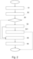
- Fig. 2 shows a flow chart of a passenger monitoring method.
- the passenger monitoring method is performed not necessarily in this order.
- the method comprises the steps of:
- the specific pattern reorganization S5 is to be maintained without displaying the image on the displaying element.
Landscapes
- Engineering & Computer Science (AREA)
- Chemical & Material Sciences (AREA)
- Combustion & Propulsion (AREA)
- Transportation (AREA)
- Mechanical Engineering (AREA)
- General Health & Medical Sciences (AREA)
- Health & Medical Sciences (AREA)
- Oral & Maxillofacial Surgery (AREA)
- Human Computer Interaction (AREA)
- Physics & Mathematics (AREA)
- General Physics & Mathematics (AREA)
- Multimedia (AREA)
- Theoretical Computer Science (AREA)
- Fittings On The Vehicle Exterior For Carrying Loads, And Devices For Holding Or Mounting Articles (AREA)
- Traffic Control Systems (AREA)
Abstract
Description
- The present disclosure relates to a passenger monitoring system for a vehicle, a vehicle comprising such a passenger monitoring system, a passenger monitoring method for a vehicle and a computer program element for passenger monitoring in a vehicle.
- Automated driving technology provides comfort to occupants of a vehicle by taking over operational decisions to propel the vehicle without any human control. Accordingly, a driver of the vehicle may engage in other tasks than driving. An infotainment system is generally integrated in the vehicle to provide information and entertainment visually and audibly to the occupants. Thus, the driver can utilize the infotainment system via a human-machine interface during the vehicle travels in an automated driving mode. As one of the several possible tasks, the driver can actively monitor an ongoing situation inside the vehicle, which may be not visible to the driver.
- Hence, there may be a need to provide an improved passenger monitoring system, which may facilitate a driver to monitor a vehicle cabin during an automated driving mode of the vehicle.
- The problem is at least partially solved or alleviated by the subject matter of the independent claims of the present disclosure, wherein further examples are incorporated in the dependent claims. It should be noted that the aspects of the disclosure described in the following apply to the passenger monitoring system, a vehicle comprising such a passenger monitoring system, the passenger monitoring method for a vehicle and the computer program element for passenger monitoring in a vehicle.
- According to the present disclosure, a passenger monitoring system for a vehicle is presented. The passenger monitoring system comprises a human-machine interface unit, a passenger monitoring unit and a control unit. The human-machine interface unit comprises at least a displaying element. The displaying element is arranged facing a user. The passenger monitoring unit is arranged to generate image data of a passenger sitting in the vehicle. The control unit is configured to receive information on a driving mode of the vehicle. The control unit is configured to cause the displaying element to display an image based on the image data generated by the passenger monitoring unit, when an autonomous driving mode is activated.
- The passenger monitoring system according to the present disclosure may provide an integrated monitoring system of a vehicle cabin. In particular, the passenger monitoring system may be able to provide a driver with visual information about the vehicle cabin, even over an area such as a rear seating area of the vehicle, which is generally invisible to the driver. However, a position of the passenger to be monitored is not limited to the rear seating area, but may be any position in the vehicle cabin. Further, the passenger monitoring system may be able to adapt currently monitored situation to improve its monitoring ability and/or assist a decision to be processed to react to the currently monitored situation. Accordingly, safety of the vehicle during travelling can be increased.
- The human-machine interface unit may be configured to interact with a user, i.e. the driver. Accordingly, the human-machine interface unit may be able to receive an input from the user and provide an output in response to the received input. Specifically, the human-machine interface unit may be configured to provide information of the passenger to be monitored to the driver.
- The human-machine interface unit may adapt one or more user-friendly applications to facilitate communication between the user and the control unit of the vehicle. The human-machine interface unit may allow the user to enter an input via a (touch) screen, a voice control and/or a gesture control. Accordingly, the user may have an easy access to the control unit via the human-machine interface unit. The human-machine interface unit may be a part of an infotainment system of the vehicle. Accordingly, the passenger monitoring system may not require any new components in the vehicle, but apply the infotainment system, which is generally integrated in the vehicle.
- The displaying element of the human-machine interface unit may be arranged in a driver's visual field. Accordingly, the displaying element may be arranged at a front side of the driver. For instance, the displaying element may be integrated in a Center Stack Display (SCD), Head Up Display (HUD), Drivers Information Module (DIM) and/or Infotainment Head Unit (IHU). However, in case the driver may be able to adjust a driver's seat depending on a level of the autonomous driving mode, the displaying element may be arranged such that the displaying element is positioned in a field of driver's view, e.g. facing the driver or the user, allowing a comfortable monitoring.
- The passenger monitoring unit may comprise at least one optical image sensor such as a camera. The optical image sensor may be arranged at the position, where the passenger and/or a passenger seat of the passenger may be reliably monitored. For instance, the optical image sensor may face the passenger and/or the passenger seat to be monitored. The passenger monitoring unit may be configured to capture at least one image of the passenger and generate image data. In other words, the passenger monitoring unit, particularly the optical image sensor, may be also able to generate photo image data and/or video image data.
- The control unit may be an electronic control unit (ECU). The control unit may include, for example, one or more central processing units (CPUs), graphics processing units (GPUs) dedicated to performing calculations/transactions and/or other processing devices. The control unit may be able to communicate, control and/or retrieve information from the passenger monitoring unit via a wired or wireless connection.
- The control unit may be adapted to communicate with a drive pilot unit of the vehicle, which may be configured to determine a driving mode and/or perform the determined driving mode. Specifically, the control unit may receive information indicating the driving mode such as manual, automated driving (AD) and/or advanced driver assistance system (ADAS).
- The control unit may be further configured to decide if it is safe to display the image data generated by the passenger monitoring unit on the displaying element of the human-machine interface with respect to the driving mode of the vehicle. The driving mode of the vehicle may be defined according to levels of autonomous driving from level 0 to
level 5. For instance, the control unit may classify level 3 (conditional driving automation) to level 5 (full driving automation) as a safe driving mode for displaying the captured image. Hence, the expression "autonomous driving mode is activated" may be understood such that the level of the autonomous driving mode may be changed into the said range of the autonomous driving level. - Thus, when the control unit identifies the safe driving mode, the control unit may allow the displaying element to display the passenger image based on the image data. In other words, the displaying element may display the passenger to be monitored, when the autonomous driving mode is activated. Still in other words, the control unit may turn on the displaying element to display the passenger image, when the vehicle is operated within an operational design domain.
- In an example, the autonomous driving mode may be an unsupervised autonomous driving mode and the control unit may allow the displaying unit to display the passenger only when the vehicle is operated under the unsupervised autonomous driving mode, which may correspond to
level 4 orlevel 5 of the autonomous driving. - In an example, the control unit is further configured to turn off the image of the passenger shown on the displaying element, when the autonomous driving mode is deactivated, and the passenger monitoring unit is configured to continue generating the image data of the passenger.
- The term "deactivated" may be understood such that the level of the autonomous driving mode may be changed into a supervised driving mode. The control unit may be adapted to continuously communicate with the drive pilot unit of the vehicle to receive the ongoing information on the driving mode of the vehicle. As soon as the level of the autonomous driving level is under 3, the control unit may turn off the displaying unit to stop displaying the monitoring image of the passenger.
- However, even though the displaying element changes its content from the passenger image due to the changed driving mode, the passenger monitoring unit may continue monitoring the passenger and generating respective image data. Accordingly, safety of the vehicle can be improved.
- In an example, the control unit is further configured to store the image data generated by the passenger monitoring unit in a storage medium element. The passenger monitoring system may be coupled with an external storage medium element. Additionally or alternatively, the storage medium element may be integrated in the passenger monitoring system. The control unit may be adapted to transfer data from the passenger monitoring unit to the data storage medium to store the captured image data via a wired or wireless connection.
- The storage medium element may comprise internal to a computing device, such as a computer's SSD, or a removable device such as an external HDD or universal serial bus (USB) flash drive. There are also other types of medium element, including magnetic tape, compact discs (CDs) and non-volatile memory (NVM) cards. The storage medium element may be also a cloud-based data storage element.
- In an example, the human-machine interface unit is configured to receive a user's input to tag the displayed image and/or display an image of the previously generated image data of the passenger. The human-machine interface unit may be adapted to receive the user's input regarding handling the captured image. The input may be entered to the human-machine interface unit via the touch control, the voice control and/or the gesture control of the user. The user's input may comprise at least one of tagging, recording, replaying the image currently captured and replaying the image stored in the storage medium element.
- In an example, the human-machine interface unit further comprises an audio element, and the control unit is configured to generate an audio message via the audio element to the user. The audio element may be adapted to receive a voice input of the user and/or provide an audio output. Preferably, the audio element may be configured to generate an audio message to the user when the autonomous driving mode is deactivated. Accordingly, when the autonomous driving mode is deactivated and the displaying element stops displaying the monitoring image captured by the passenger monitoring unit, the control unit is able to allow the human-machine interface unit to generate the audio message to inform the user and/or the driver about the change of the driving mode.
- In an example, the passenger monitoring unit comprises a vision-based perception element, and the vision-based perception element is configured to recognize at least one specific pattern of the passenger. The vision-based perception element may be adapted to identify a typical behavior, motion, state, pose, gesture, emotion and/or facial expression of the passenger to be monitored. The vision-based perception element may be further adapted to recognize a different pattern of the behavior, motion, state, pose, gesture, emotion and/or facial expression of the passenger by comparing the currently captured image data with the image data stored in the storage medium element.
- In an example, the vision-based perception element is configured to analyze a countenance of the passenger in the image data generated currently based on the image data stored in the storage medium element. The passenger monitoring unit may be able to recognize a pattern change of the countenance of the passenger in the image data, which is currently generated by the optical image sensor and compare with the image data stored in the storage medium element. When analyzing the countenance of the passenger, the vision-based perception element may also incorporate the user's input such as a tag. The pattern change and/or the analysis of the countenance of the passenger may be related to the emotion and/or the facial expression of the passenger.
- In an example, the vision-based perception element is further configured to identify a behavior change of the passenger based on the image data stored in the storage medium element. The passenger monitoring unit may be able to recognize the behavior change of the passenger in the image data, which is currently generated by the optical image sensor, based on the pattern change, i.e. by comparing with the image data stored in the storage medium element. The pattern change directing to the behavior change of the passenger may be related to the motion, the gesture and/or the pose of the passenger to be monitored.
- In an example, the control unit is configured to generate the audio message via the audio element to the user, when the countenance and/or the behavior change signifies a specific event of the passenger. The vision-based perception element may be able to identify a remarkable change of the passenger's state based on the countenance analysis and/or the behavior change by applying the machine learning. The remarkable change of the passenger's state may be, for instance, falling asleep, waking up, getting bored, getting tense, changing position, etc. The generation of the audio message may be configurable such that one or more remarkable changes may be performed by default. For instance, user may be able to set up the remarkable changes, which can be classified as default, via the human-machine interface unit.
- Such specific event may be tagged or denoted by the user and/or identified by the machine learning. Accordingly, if the passenger monitoring unit, preferably the vision-based perception element, recognizes a remarkable change of the state of the passenger, the passenger monitoring unit may provide the control unit such information in order to signal the specific event to the user and/or the driver. Such signal may be provided by means of an audio message via the audio element of the human-machine interface unit and/or a visual sign or text via the displaying element of the human-machine interface unit to awake the user's attention.
- In an example, the control unit is further configured to send one or more images displayed on the displaying element to an external device via a wireless network element. The control unit may be able to identify or decide, which image data may be interesting or attractive to the user based on the user's input and/or the identified specific event. If the control unit identifies the specific event of the passenger, which may be interesting to the user, the control unit may send such image data to the external device of the user, such as a mobile device, over the air. Additionally or alternatively, the user may be also capable to select and transmitting the image data via the human-machine interface unit.
- The wireless network element may be configured to communicate with an external computing device over the air. The wireless network element may comprise LTE, 5G, Wi-Fi, Bluetooth, NFC, etc. The control unit may thus transmit the selected image data to the external device, which may be any network-compatible devices such as a smartphone, a smartwatch, a tablet, a computer, etc. The external device may be also a cloud-based data storage element. Accordingly, the user may have an easy access to the selected image and/or video clip anywhere.
- In an example, the passenger monitoring unit is configured to monitor a child. The passenger to be monitored may be a baby or a child sitting in a child car seat. Specifically, in case of an infant carrier car seat, the driver may have difficulty to safely monitor the baby. In such a case, the passenger monitoring unit, in particular the optical image sensor or the camera may be arranged to reliably generate image data of the baby.
- In an example, the passenger monitoring unit is configured to monitor a disabled person aided by an equipment. The passenger to be monitored may be a person, who may require an assistance equipment such as a wheelchair, respiratory equipment, etc. The passenger monitoring unit may be adapted to assist monitoring such disabled person or infirm person sitting in the vehicle.
- In an example, the passenger monitoring unit may be also configured to monitor one or more pets travelling in the vehicle.
- According to the present disclosure, a vehicle is presented. The vehicle comprises a passenger monitoring unit as described above. The vehicle may further comprises a drive pilot unit, which may communicate with the control unit of the passenger monitoring system to control turning-on and/or -off of a displaying element of a passenger monitoring unit based on a driving mode of the vehicle. For instance, the control unit may allow the displaying element to show an image based on the image data generated by the passenger monitoring unit, when an autonomous driving mode is activated. Further, the control unit may prompt the displaying element to be turned off or at least change from a passenger monitoring mode to a general information mode providing ongoing operational information of the vehicle, when the autonomous driving mode is deactivated.
- According to the present disclosure, a passenger monitoring method is presented. The method comprises the steps of:
- receiving information on a driving mode of the vehicle,
- generating image data of a passenger, and
- displaying an image based on the image data generated by a passenger monitoring unit in a displaying element, when an autonomous driving mode is activated.
- According to the present disclosure, a computer program element is presented. The computer program element is configured for passenger monitoring in a vehicle as described above, which, when being executed by a processing element, is adapted to perform the method steps of a method claim as described above.
- According to the present disclosure, one or more computer storage media may be presented. The computer storage media may be encoded with instructions that, when executed by one or more computers, cause the one or more computers to perform the operations of the respective method as described above.
- The computer storage media may comprise at least one memory device in any form of volatile or non-volatile computer readable memory including, without limitation, persistent storage, solid-state memory, remotely mounted memory, magnetic media, optical media, random access memory (RAM), read-only memory (ROM), mass storage media (for example, a hard disk), removable storage media (for example, a flash drive, a Compact Disk (CD) or a Digital Video Disk (DVD)), and/or any other volatile or non-volatile, non-transitory device readable and/or computer-executable memory devices that store information, data, and/or instructions that may be used by the control unit.
- According to the present disclosure, a computer system may be also presented. The computer system may comprise one or more computer storage media as described above, and one or more computers for executing the instructions.
- It should be noted that the above examples may be combined with each other irrespective of the aspect involved. Accordingly, the method may be combined with structural features and, likewise, the system may be combined with features described above with regard to the method.
- These and other examples of the present disclosure will become apparent from and elucidated with reference to the embodiments described hereinafter.
- Examples according to the present disclosure will be described in the following with reference to the following drawings.
- Fig. 1
- shows schematically and exemplarily an example of a vehicle comprising a passenger monitoring system according to the present disclosure.
- Fig. 2
- shows schematically and exemplarily an example of a flow chart of a method for passenger monitoring according to the present disclosure.
-
Fig. 1 shows apassenger monitoring system 1 for avehicle 100. Thepassenger monitoring system 1 is configured to monitor at least one passenger, for instance a child sitting in a child seat and or a disabled person aided by an equipment. Thepassenger monitoring system 1 ensures a safe monitoring of the passenger. Thepassenger monitoring system 1 comprises a human-machine interface unit 10, apassenger monitoring unit 20 and acontrol unit 30. - The human-
machine interface unit 10 comprises at least a displayingelement 11. The displayingelement 11 is arranged facing a user (not shown). The human-machine interface unit 10 further comprises anaudio element 12. The human-machine interface unit 10 is able to receive an input from the user and provide an output in response to the received input. For instance, the human-machine interface unit 10 is able to receive a user's input to tag a displayed image on the displayingelement 11 and/or display an image of the previously generated image data of the passenger. - The
passenger monitoring unit 20 is arranged to generate image data of a passenger (not shown) sitting in thevehicle 100. Thepassenger monitoring unit 20 comprises at least oneoptical image sensor 21 adapted to generate image data of the passenger to be monitored. Thecontrol unit 30 is also configured to store the image data generated by thepassenger monitoring unit 20 in astorage medium element 40 via a wired or wireless connection. - The
passenger monitoring unit 20 further comprises a vision-basedperception element 22 configured to recognize at least one specific pattern of the passenger in the image captured by theoptical image sensor 21. For instance, the vision-basedperception element 22 is able to analyze a countenance of the passenger in the currently generated image data based on the image data stored in thestorage medium element 40. The vision-basedperception element 22 is further able to identify a behavior change of the passenger based on the image data stored in thestorage medium element 40. - The
control unit 30 is configured to receive information on a driving mode of thevehicle 100. Thecontrol unit 30 is configured to cause the displayingelement 11 to display an image based on the image data generated by thepassenger monitoring unit 20, when an autonomous driving mode is activated. Thecontrol unit 30 is further configured to turn off the monitoring image of the passenger on the displayingelement 11, when the autonomous driving mode is deactivated. Even though the displaying element does not display the ongoing monitoring image data, thepassenger monitoring unit 20 continues generating the image data of the passenger. - The
control unit 30 is also able to generate an audio message via theaudio element 12 to the user. Particularly, thecontrol unit 30 is configured to generate an audio message via theaudio element 12 to the user, when the countenance and/or the behavior change signifies a specific event of the passenger. - The
control unit 30 is further configured to send one or more images displayed on the displayingelement 11 to an external device (not shown) via awireless network element 31. Thecontrol unit 30 may be able to identify or decide, which image data may be interesting or attractive to the user based on the user's input and/or the identified specific event. -
Fig. 2 shows a flow chart of a passenger monitoring method. The passenger monitoring method is performed not necessarily in this order. The method comprises the steps of: - S1: receiving information on a driving mode of the vehicle,
- S2: generating photo image data or video image data of the passenger to be monitored,
- S3: checking if an autonomous driving mode is activated,
- S4: displaying an image based on image data generated by a passenger monitoring unit in a displaying element,
- S41: receiving a user's input to tag or record the displayed image,
- S5: recognizing at least one specific pattern of the passenger, and
- S6: generating an audio massage to the user.
- If it is confirmed in the step S3 that the autonomous driving mode is deactivated, the specific pattern reorganization S5 is to be maintained without displaying the image on the displaying element.
- It has to be noted that examples of the disclosure are described with reference to different subject matters. In particular, some examples are described with reference to method type claims whereas other examples are described with reference to the device type claims. However, a person skilled in the art will gather from the above and the following description that, unless otherwise notified, in addition to any combination of features belonging to one type of subject matter also any combination between features relating to different subject matters is considered to be disclosed with this application. However, all features can be combined providing synergetic effects that are more than the simple summation of the features.
- While the disclosure has been illustrated and described in detail in the drawings and description, such illustration and description are to be considered illustrative or exemplary and not restrictive. The disclosure is not limited to the disclosed examples. Other variations to the disclosed examples can be understood and effected by those skilled in the art in practicing a claimed disclosure, from a study of the drawings, the disclosure, and the dependent claims.
- In the claims, the word "comprising" does not exclude other elements or steps, and the indefinite article "a" or "an" does not exclude a plurality. A single processor or other unit may fulfil the functions of several items recited in the claims. The mere fact that certain measures are recited in mutually different dependent claims does not indicate that a combination of these measures cannot be used to advantage. Any reference signs in the claims should not be construed as limiting the scope.
Claims (15)
- A passenger monitoring system (1) for a vehicle (100), comprising- a human-machine interface unit (10),- a passenger monitoring unit (20), and- a control unit (30),the human-machine interface unit (10) comprising at least a displaying element (11),the displaying element (11) being arranged facing a user,the passenger monitoring unit (20) being arranged to generate image data of a passenger sitting in the vehicle (100),the control unit (30) being configured to receive information on a driving mode of the vehicle (100), andthe control unit (30) being configured to cause the displaying element (11) to display an image based on the image data generated by the passenger monitoring unit (20), when an autonomous driving mode is activated.
- The passenger monitoring system (1) according to claim 1, the control unit (30) being further configured to turn off the image of the passenger on the displaying element (11), when the autonomous driving mode is deactivated, and the passenger monitoring unit (20) being configured to continue generating the image data of the passenger.
- The passenger monitoring system (1) according to claim 1 or 2, the control unit (30) being further configured to store the image data generated by the passenger monitoring unit (20) in a storage medium element.
- The passenger monitoring system (1) according to any of the preceding claims, the human-machine interface unit (10) being configured to receive a user's input to tag the displayed image and/or display an image of the previously generated image data of the passenger.
- The passenger monitoring system (1) according to any of the preceding claims, the human-machine interface unit (10) further comprising an audio element (12), and the control unit (30) being configured to generate an audio message via the audio element (12) to the user.
- The passenger monitoring system (1) according to any of the preceding claims, the passenger monitoring unit (20) comprising a vision-based perception element (22), and the vision-based perception element (22) being configured to recognize at least one specific pattern of the passenger.
- The passenger monitoring system (1) according to the preceding claim, the vision-based perception element (22) being configured to analyze a countenance of the passenger in the image data generated currently based on the image data stored in the storage medium element (40).
- The passenger monitoring system (1) according to claim 6 or 7, the vision-based perception element (22) being further configured to identify a behavior change of the passenger based on the image data stored in the storage medium element (40).
- The passenger monitoring system (1) according to any of the preceding claims, the control unit (30) being configured to generate the audio message via the audio element (12) to the user, when the countenance and/or the behavior change signifies a specific event of the passenger.
- The passenger monitoring system (1) according to any of the preceding claims, the control unit (30) being further configured to send one or more images displayed on the displaying element (11) to an external device via a wireless network element (31).
- The passenger monitoring system (1) according to any of the preceding claims, the passenger monitoring unit (20) being configured to monitor a child sitting in a child seat.
- The passenger monitoring system (1) according to any of the preceding claims, the passenger monitoring unit (20) being configured to monitor a disabled person aided by an equipment.
- A vehicle (100) comprising a passenger monitoring system (1) according to any of the preceding claims 1 to 12.
- A passenger monitoring method for a vehicle (100), comprising- receiving (S1) information on a driving mode of the vehicle (100),- generating (S2) image data of a passenger, and- displaying (S4) an image based on the image data generated by a passenger monitoring unit (20) in a displaying element (11), when an autonomous driving mode is activated,a human-machine interface unit (10) comprising at least the displaying element (11).
- A computer program element for passenger monitoring in a vehicle (100) according to claim 13, which, when being executed by a processing element, being adapted to perform the method steps according to claim 14.
Priority Applications (2)
| Application Number | Priority Date | Filing Date | Title |
|---|---|---|---|
| EP22186974.6A EP4311707B1 (en) | 2022-07-26 | 2022-07-26 | Passenger monitoring system |
| EP22198738.1A EP4311709B1 (en) | 2022-07-26 | 2022-09-29 | On-board passenger assistance system and method for vehicle and vehicle |
Applications Claiming Priority (1)
| Application Number | Priority Date | Filing Date | Title |
|---|---|---|---|
| EP22186974.6A EP4311707B1 (en) | 2022-07-26 | 2022-07-26 | Passenger monitoring system |
Publications (2)
| Publication Number | Publication Date |
|---|---|
| EP4311707A1 true EP4311707A1 (en) | 2024-01-31 |
| EP4311707B1 EP4311707B1 (en) | 2024-11-13 |
Family
ID=82742951
Family Applications (2)
| Application Number | Title | Priority Date | Filing Date |
|---|---|---|---|
| EP22186974.6A Active EP4311707B1 (en) | 2022-07-26 | 2022-07-26 | Passenger monitoring system |
| EP22198738.1A Active EP4311709B1 (en) | 2022-07-26 | 2022-09-29 | On-board passenger assistance system and method for vehicle and vehicle |
Family Applications After (1)
| Application Number | Title | Priority Date | Filing Date |
|---|---|---|---|
| EP22198738.1A Active EP4311709B1 (en) | 2022-07-26 | 2022-09-29 | On-board passenger assistance system and method for vehicle and vehicle |
Country Status (1)
| Country | Link |
|---|---|
| EP (2) | EP4311707B1 (en) |
Citations (3)
| Publication number | Priority date | Publication date | Assignee | Title |
|---|---|---|---|---|
| US20170313248A1 (en) * | 2014-09-19 | 2017-11-02 | Be Topnotch, Llc | Display rear passenger view on a display screen in vehicle |
| US20170330044A1 (en) * | 2016-05-10 | 2017-11-16 | GM Global Technology Operations LLC | Thermal monitoring in autonomous-driving vehicles |
| US20220207278A1 (en) * | 2020-12-28 | 2022-06-30 | Toyota Motor Engineering & Manufacturing North America, Inc. | Camera system to monitor the passengers in a vehicle and detect passenger activities |
Family Cites Families (2)
| Publication number | Priority date | Publication date | Assignee | Title |
|---|---|---|---|---|
| US11067405B2 (en) * | 2010-06-07 | 2021-07-20 | Affectiva, Inc. | Cognitive state vehicle navigation based on image processing |
| US20210261050A1 (en) * | 2020-02-21 | 2021-08-26 | Cobalt Industries Inc. | Real-time contextual vehicle lighting systems and methods |
-
2022
- 2022-07-26 EP EP22186974.6A patent/EP4311707B1/en active Active
- 2022-09-29 EP EP22198738.1A patent/EP4311709B1/en active Active
Patent Citations (3)
| Publication number | Priority date | Publication date | Assignee | Title |
|---|---|---|---|---|
| US20170313248A1 (en) * | 2014-09-19 | 2017-11-02 | Be Topnotch, Llc | Display rear passenger view on a display screen in vehicle |
| US20170330044A1 (en) * | 2016-05-10 | 2017-11-16 | GM Global Technology Operations LLC | Thermal monitoring in autonomous-driving vehicles |
| US20220207278A1 (en) * | 2020-12-28 | 2022-06-30 | Toyota Motor Engineering & Manufacturing North America, Inc. | Camera system to monitor the passengers in a vehicle and detect passenger activities |
Also Published As
| Publication number | Publication date |
|---|---|
| EP4311709A1 (en) | 2024-01-31 |
| EP4311709B1 (en) | 2025-03-12 |
| EP4311707B1 (en) | 2024-11-13 |
Similar Documents
| Publication | Publication Date | Title |
|---|---|---|
| KR102446686B1 (en) | Passenger condition analysis method and device, vehicle, electronic device, storage medium | |
| EP3725470B1 (en) | Robot reacting on basis of user behavior and control method therefor | |
| US11430231B2 (en) | Emotion estimation device and emotion estimation method | |
| US11292490B2 (en) | Contextual autonomous vehicle support through pictorial interaction | |
| US10752172B2 (en) | System and method to control a vehicle interface for human perception optimization | |
| KR20200077554A (en) | Methods and devices for analyzing the condition of children, vehicles, electronic devices, storage media | |
| EP3637228B1 (en) | Real-time motion feedback for extended reality | |
| EP4177852A1 (en) | Method for automatically controlling in-cabin environment for passenger and system therefor | |
| Diederichs et al. | Adaptive transitions for automation in cars, trucks, buses and motorcycles | |
| JP2022032377A (en) | Vehicle and control method therefor | |
| Barisic et al. | Driver model for take-over-request in autonomous vehicles | |
| CN112823383A (en) | Information providing device and information providing method | |
| EP4311707B1 (en) | Passenger monitoring system | |
| CN110525443A (en) | Method and apparatus for identifying driver fatigue of a vehicle in a mobile device | |
| CN115457519A (en) | Multi-mode-based recognition method and device, electronic equipment and storage medium | |
| EP2759895A2 (en) | System and method for automatically and dynamically varying the feedback to an operator by an automated system | |
| US20250114022A1 (en) | Driving assistance device, driving assistance method, and storage medium | |
| More et al. | Web-based Emergency Alert System for Driver's Drowsiness and Medical Exigency | |
| WO2021176633A1 (en) | Driver state estimation device and driver state estimation method | |
| JP7722334B2 (en) | In-vehicle systems | |
| US12246739B2 (en) | Adaptive driving style | |
| KR102322863B1 (en) | Apparatus and method for providing information based on a current task of a user | |
| JP2026070966A (en) | system | |
| Moraitis et al. | Design of a Sophisticated Driver Drowsiness Detection System | |
| KR102613180B1 (en) | Vehicle and control method for the same |
Legal Events
| Date | Code | Title | Description |
|---|---|---|---|
| PUAI | Public reference made under article 153(3) epc to a published international application that has entered the european phase |
Free format text: ORIGINAL CODE: 0009012 |
|
| STAA | Information on the status of an ep patent application or granted ep patent |
Free format text: STATUS: REQUEST FOR EXAMINATION WAS MADE |
|
| 17P | Request for examination filed |
Effective date: 20230418 |
|
| AK | Designated contracting states |
Kind code of ref document: A1 Designated state(s): AL AT BE BG CH CY CZ DE DK EE ES FI FR GB GR HR HU IE IS IT LI LT LU LV MC MK MT NL NO PL PT RO RS SE SI SK SM TR |
|
| REG | Reference to a national code |
Ref country code: DE Ref legal event code: R079 Free format text: PREVIOUS MAIN CLASS: B60K0037060000 Ipc: G06V0040160000 Ref document number: 602022007646 Country of ref document: DE |
|
| GRAP | Despatch of communication of intention to grant a patent |
Free format text: ORIGINAL CODE: EPIDOSNIGR1 |
|
| GRAP | Despatch of communication of intention to grant a patent |
Free format text: ORIGINAL CODE: EPIDOSNIGR1 |
|
| STAA | Information on the status of an ep patent application or granted ep patent |
Free format text: STATUS: GRANT OF PATENT IS INTENDED |
|
| RIC1 | Information provided on ipc code assigned before grant |
Ipc: B60K 35/10 20240101ALI20240529BHEP Ipc: B60K 35/28 20240101ALI20240529BHEP Ipc: G06F 3/14 20060101ALI20240529BHEP Ipc: B60K 37/00 20240101ALI20240529BHEP Ipc: G06V 40/16 20220101AFI20240529BHEP |
|
| INTG | Intention to grant announced |
Effective date: 20240614 |
|
| GRAS | Grant fee paid |
Free format text: ORIGINAL CODE: EPIDOSNIGR3 |
|
| GRAA | (expected) grant |
Free format text: ORIGINAL CODE: 0009210 |
|
| STAA | Information on the status of an ep patent application or granted ep patent |
Free format text: STATUS: THE PATENT HAS BEEN GRANTED |
|
| AK | Designated contracting states |
Kind code of ref document: B1 Designated state(s): AL AT BE BG CH CY CZ DE DK EE ES FI FR GB GR HR HU IE IS IT LI LT LU LV MC MK MT NL NO PL PT RO RS SE SI SK SM TR |
|
| REG | Reference to a national code |
Ref country code: GB Ref legal event code: FG4D |
|
| REG | Reference to a national code |
Ref country code: CH Ref legal event code: EP |
|
| P01 | Opt-out of the competence of the unified patent court (upc) registered |
Free format text: CASE NUMBER: APP_57991/2024 Effective date: 20241023 |
|
| REG | Reference to a national code |
Ref country code: IE Ref legal event code: FG4D |
|
| REG | Reference to a national code |
Ref country code: DE Ref legal event code: R096 Ref document number: 602022007646 Country of ref document: DE |
|
| REG | Reference to a national code |
Ref country code: LT Ref legal event code: MG9D |
|
| REG | Reference to a national code |
Ref country code: NL Ref legal event code: MP Effective date: 20241113 |
|
| PG25 | Lapsed in a contracting state [announced via postgrant information from national office to epo] |
Ref country code: IS Free format text: LAPSE BECAUSE OF FAILURE TO SUBMIT A TRANSLATION OF THE DESCRIPTION OR TO PAY THE FEE WITHIN THE PRESCRIBED TIME-LIMIT Effective date: 20250313 Ref country code: PT Free format text: LAPSE BECAUSE OF FAILURE TO SUBMIT A TRANSLATION OF THE DESCRIPTION OR TO PAY THE FEE WITHIN THE PRESCRIBED TIME-LIMIT Effective date: 20250313 Ref country code: HR Free format text: LAPSE BECAUSE OF FAILURE TO SUBMIT A TRANSLATION OF THE DESCRIPTION OR TO PAY THE FEE WITHIN THE PRESCRIBED TIME-LIMIT Effective date: 20241113 |
|
| PG25 | Lapsed in a contracting state [announced via postgrant information from national office to epo] |
Ref country code: FI Free format text: LAPSE BECAUSE OF FAILURE TO SUBMIT A TRANSLATION OF THE DESCRIPTION OR TO PAY THE FEE WITHIN THE PRESCRIBED TIME-LIMIT Effective date: 20241113 Ref country code: NL Free format text: LAPSE BECAUSE OF FAILURE TO SUBMIT A TRANSLATION OF THE DESCRIPTION OR TO PAY THE FEE WITHIN THE PRESCRIBED TIME-LIMIT Effective date: 20241113 |
|
| REG | Reference to a national code |
Ref country code: AT Ref legal event code: MK05 Ref document number: 1742293 Country of ref document: AT Kind code of ref document: T Effective date: 20241113 |
|
| PG25 | Lapsed in a contracting state [announced via postgrant information from national office to epo] |
Ref country code: BG Free format text: LAPSE BECAUSE OF FAILURE TO SUBMIT A TRANSLATION OF THE DESCRIPTION OR TO PAY THE FEE WITHIN THE PRESCRIBED TIME-LIMIT Effective date: 20241113 |
|
| PG25 | Lapsed in a contracting state [announced via postgrant information from national office to epo] |
Ref country code: ES Free format text: LAPSE BECAUSE OF FAILURE TO SUBMIT A TRANSLATION OF THE DESCRIPTION OR TO PAY THE FEE WITHIN THE PRESCRIBED TIME-LIMIT Effective date: 20241113 |
|
| PG25 | Lapsed in a contracting state [announced via postgrant information from national office to epo] |
Ref country code: NO Free format text: LAPSE BECAUSE OF FAILURE TO SUBMIT A TRANSLATION OF THE DESCRIPTION OR TO PAY THE FEE WITHIN THE PRESCRIBED TIME-LIMIT Effective date: 20250213 |
|
| PG25 | Lapsed in a contracting state [announced via postgrant information from national office to epo] |
Ref country code: LV Free format text: LAPSE BECAUSE OF FAILURE TO SUBMIT A TRANSLATION OF THE DESCRIPTION OR TO PAY THE FEE WITHIN THE PRESCRIBED TIME-LIMIT Effective date: 20241113 Ref country code: AT Free format text: LAPSE BECAUSE OF FAILURE TO SUBMIT A TRANSLATION OF THE DESCRIPTION OR TO PAY THE FEE WITHIN THE PRESCRIBED TIME-LIMIT Effective date: 20241113 Ref country code: GR Free format text: LAPSE BECAUSE OF FAILURE TO SUBMIT A TRANSLATION OF THE DESCRIPTION OR TO PAY THE FEE WITHIN THE PRESCRIBED TIME-LIMIT Effective date: 20250214 |
|
| PG25 | Lapsed in a contracting state [announced via postgrant information from national office to epo] |
Ref country code: PL Free format text: LAPSE BECAUSE OF FAILURE TO SUBMIT A TRANSLATION OF THE DESCRIPTION OR TO PAY THE FEE WITHIN THE PRESCRIBED TIME-LIMIT Effective date: 20241113 |
|
| PG25 | Lapsed in a contracting state [announced via postgrant information from national office to epo] |
Ref country code: RS Free format text: LAPSE BECAUSE OF FAILURE TO SUBMIT A TRANSLATION OF THE DESCRIPTION OR TO PAY THE FEE WITHIN THE PRESCRIBED TIME-LIMIT Effective date: 20250213 |
|
| PG25 | Lapsed in a contracting state [announced via postgrant information from national office to epo] |
Ref country code: SM Free format text: LAPSE BECAUSE OF FAILURE TO SUBMIT A TRANSLATION OF THE DESCRIPTION OR TO PAY THE FEE WITHIN THE PRESCRIBED TIME-LIMIT Effective date: 20241113 |
|
| PG25 | Lapsed in a contracting state [announced via postgrant information from national office to epo] |
Ref country code: DK Free format text: LAPSE BECAUSE OF FAILURE TO SUBMIT A TRANSLATION OF THE DESCRIPTION OR TO PAY THE FEE WITHIN THE PRESCRIBED TIME-LIMIT Effective date: 20241113 |
|
| PG25 | Lapsed in a contracting state [announced via postgrant information from national office to epo] |
Ref country code: EE Free format text: LAPSE BECAUSE OF FAILURE TO SUBMIT A TRANSLATION OF THE DESCRIPTION OR TO PAY THE FEE WITHIN THE PRESCRIBED TIME-LIMIT Effective date: 20241113 |
|
| PGFP | Annual fee paid to national office [announced via postgrant information from national office to epo] |
Ref country code: FR Payment date: 20250619 Year of fee payment: 4 |
|
| PG25 | Lapsed in a contracting state [announced via postgrant information from national office to epo] |
Ref country code: RO Free format text: LAPSE BECAUSE OF FAILURE TO SUBMIT A TRANSLATION OF THE DESCRIPTION OR TO PAY THE FEE WITHIN THE PRESCRIBED TIME-LIMIT Effective date: 20241113 |
|
| PG25 | Lapsed in a contracting state [announced via postgrant information from national office to epo] |
Ref country code: SK Free format text: LAPSE BECAUSE OF FAILURE TO SUBMIT A TRANSLATION OF THE DESCRIPTION OR TO PAY THE FEE WITHIN THE PRESCRIBED TIME-LIMIT Effective date: 20241113 |
|
| PG25 | Lapsed in a contracting state [announced via postgrant information from national office to epo] |
Ref country code: CZ Free format text: LAPSE BECAUSE OF FAILURE TO SUBMIT A TRANSLATION OF THE DESCRIPTION OR TO PAY THE FEE WITHIN THE PRESCRIBED TIME-LIMIT Effective date: 20241113 |
|
| PG25 | Lapsed in a contracting state [announced via postgrant information from national office to epo] |
Ref country code: IT Free format text: LAPSE BECAUSE OF FAILURE TO SUBMIT A TRANSLATION OF THE DESCRIPTION OR TO PAY THE FEE WITHIN THE PRESCRIBED TIME-LIMIT Effective date: 20241113 |
|
| REG | Reference to a national code |
Ref country code: DE Ref legal event code: R097 Ref document number: 602022007646 Country of ref document: DE |
|
| PG25 | Lapsed in a contracting state [announced via postgrant information from national office to epo] |
Ref country code: SE Free format text: LAPSE BECAUSE OF FAILURE TO SUBMIT A TRANSLATION OF THE DESCRIPTION OR TO PAY THE FEE WITHIN THE PRESCRIBED TIME-LIMIT Effective date: 20241113 |
|
| PLBE | No opposition filed within time limit |
Free format text: ORIGINAL CODE: 0009261 |
|
| STAA | Information on the status of an ep patent application or granted ep patent |
Free format text: STATUS: NO OPPOSITION FILED WITHIN TIME LIMIT |
|
| PGFP | Annual fee paid to national office [announced via postgrant information from national office to epo] |
Ref country code: DE Payment date: 20250620 Year of fee payment: 4 |
|
| 26N | No opposition filed |
Effective date: 20250814 |
|
| REG | Reference to a national code |
Ref country code: CH Ref legal event code: H13 Free format text: ST27 STATUS EVENT CODE: U-0-0-H10-H13 (AS PROVIDED BY THE NATIONAL OFFICE) Effective date: 20260224 |
|
| PG25 | Lapsed in a contracting state [announced via postgrant information from national office to epo] |
Ref country code: LU Free format text: LAPSE BECAUSE OF NON-PAYMENT OF DUE FEES Effective date: 20250726 |
|
| REG | Reference to a national code |
Ref country code: BE Ref legal event code: MM Effective date: 20250731 |
|
| PG25 | Lapsed in a contracting state [announced via postgrant information from national office to epo] |
Ref country code: BE Free format text: LAPSE BECAUSE OF NON-PAYMENT OF DUE FEES Effective date: 20250731 |
|
| PG25 | Lapsed in a contracting state [announced via postgrant information from national office to epo] |
Ref country code: CH Free format text: LAPSE BECAUSE OF NON-PAYMENT OF DUE FEES Effective date: 20250731 |