EP4311698A1 - Vehicle load regulating system and method thereof - Google Patents
Vehicle load regulating system and method thereof Download PDFInfo
- Publication number
- EP4311698A1 EP4311698A1 EP23187721.8A EP23187721A EP4311698A1 EP 4311698 A1 EP4311698 A1 EP 4311698A1 EP 23187721 A EP23187721 A EP 23187721A EP 4311698 A1 EP4311698 A1 EP 4311698A1
- Authority
- EP
- European Patent Office
- Prior art keywords
- motor vehicle
- load
- processing unit
- way
- vehicle
- Prior art date
- Legal status (The legal status is an assumption and is not a legal conclusion. Google has not performed a legal analysis and makes no representation as to the accuracy of the status listed.)
- Pending
Links
Images


Classifications
-
- B—PERFORMING OPERATIONS; TRANSPORTING
- B60—VEHICLES IN GENERAL
- B60W—CONJOINT CONTROL OF VEHICLE SUB-UNITS OF DIFFERENT TYPE OR DIFFERENT FUNCTION; CONTROL SYSTEMS SPECIALLY ADAPTED FOR HYBRID VEHICLES; ROAD VEHICLE DRIVE CONTROL SYSTEMS FOR PURPOSES NOT RELATED TO THE CONTROL OF A PARTICULAR SUB-UNIT
- B60W30/00—Purposes of road vehicle drive control systems not related to the control of a particular sub-unit, e.g. of systems using conjoint control of vehicle sub-units
- B60W30/02—Control of vehicle driving stability
-
- B—PERFORMING OPERATIONS; TRANSPORTING
- B60—VEHICLES IN GENERAL
- B60G—VEHICLE SUSPENSION ARRANGEMENTS
- B60G17/00—Resilient suspensions having means for adjusting the spring or vibration-damper characteristics, for regulating the distance between a supporting surface and a sprung part of vehicle or for locking suspension during use to meet varying vehicular or surface conditions, e.g. due to speed or load
- B60G17/015—Resilient suspensions having means for adjusting the spring or vibration-damper characteristics, for regulating the distance between a supporting surface and a sprung part of vehicle or for locking suspension during use to meet varying vehicular or surface conditions, e.g. due to speed or load the regulating means comprising electric or electronic elements
- B60G17/016—Resilient suspensions having means for adjusting the spring or vibration-damper characteristics, for regulating the distance between a supporting surface and a sprung part of vehicle or for locking suspension during use to meet varying vehicular or surface conditions, e.g. due to speed or load the regulating means comprising electric or electronic elements characterised by their responsiveness, when the vehicle is travelling, to specific motion, a specific condition, or driver input
- B60G17/0162—Resilient suspensions having means for adjusting the spring or vibration-damper characteristics, for regulating the distance between a supporting surface and a sprung part of vehicle or for locking suspension during use to meet varying vehicular or surface conditions, e.g. due to speed or load the regulating means comprising electric or electronic elements characterised by their responsiveness, when the vehicle is travelling, to specific motion, a specific condition, or driver input mainly during a motion involving steering operation, e.g. cornering, overtaking
-
- B—PERFORMING OPERATIONS; TRANSPORTING
- B60—VEHICLES IN GENERAL
- B60W—CONJOINT CONTROL OF VEHICLE SUB-UNITS OF DIFFERENT TYPE OR DIFFERENT FUNCTION; CONTROL SYSTEMS SPECIALLY ADAPTED FOR HYBRID VEHICLES; ROAD VEHICLE DRIVE CONTROL SYSTEMS FOR PURPOSES NOT RELATED TO THE CONTROL OF A PARTICULAR SUB-UNIT
- B60W40/00—Estimation or calculation of non-directly measurable driving parameters for road vehicle drive control systems not related to the control of a particular sub unit, e.g. by using mathematical models
- B60W40/10—Estimation or calculation of non-directly measurable driving parameters for road vehicle drive control systems not related to the control of a particular sub unit, e.g. by using mathematical models related to vehicle motion
- B60W40/109—Lateral acceleration
-
- B—PERFORMING OPERATIONS; TRANSPORTING
- B60—VEHICLES IN GENERAL
- B60T—VEHICLE BRAKE CONTROL SYSTEMS OR PARTS THEREOF; BRAKE CONTROL SYSTEMS OR PARTS THEREOF, IN GENERAL; ARRANGEMENT OF BRAKING ELEMENTS ON VEHICLES IN GENERAL; PORTABLE DEVICES FOR PREVENTING UNWANTED MOVEMENT OF VEHICLES; VEHICLE MODIFICATIONS TO FACILITATE COOLING OF BRAKES
- B60T8/00—Arrangements for adjusting wheel-braking force to meet varying vehicular or ground-surface conditions, e.g. limiting or varying distribution of braking force
- B60T8/17—Using electrical or electronic regulation means to control braking
- B60T8/171—Detecting parameters used in the regulation; Measuring values used in the regulation
-
- B—PERFORMING OPERATIONS; TRANSPORTING
- B60—VEHICLES IN GENERAL
- B60T—VEHICLE BRAKE CONTROL SYSTEMS OR PARTS THEREOF; BRAKE CONTROL SYSTEMS OR PARTS THEREOF, IN GENERAL; ARRANGEMENT OF BRAKING ELEMENTS ON VEHICLES IN GENERAL; PORTABLE DEVICES FOR PREVENTING UNWANTED MOVEMENT OF VEHICLES; VEHICLE MODIFICATIONS TO FACILITATE COOLING OF BRAKES
- B60T8/00—Arrangements for adjusting wheel-braking force to meet varying vehicular or ground-surface conditions, e.g. limiting or varying distribution of braking force
- B60T8/17—Using electrical or electronic regulation means to control braking
- B60T8/172—Determining control parameters used in the regulation, e.g. by calculations involving measured or detected parameters
-
- B—PERFORMING OPERATIONS; TRANSPORTING
- B60—VEHICLES IN GENERAL
- B60T—VEHICLE BRAKE CONTROL SYSTEMS OR PARTS THEREOF; BRAKE CONTROL SYSTEMS OR PARTS THEREOF, IN GENERAL; ARRANGEMENT OF BRAKING ELEMENTS ON VEHICLES IN GENERAL; PORTABLE DEVICES FOR PREVENTING UNWANTED MOVEMENT OF VEHICLES; VEHICLE MODIFICATIONS TO FACILITATE COOLING OF BRAKES
- B60T8/00—Arrangements for adjusting wheel-braking force to meet varying vehicular or ground-surface conditions, e.g. limiting or varying distribution of braking force
- B60T8/18—Arrangements for adjusting wheel-braking force to meet varying vehicular or ground-surface conditions, e.g. limiting or varying distribution of braking force responsive to vehicle weight or load, e.g. load distribution
-
- B—PERFORMING OPERATIONS; TRANSPORTING
- B60—VEHICLES IN GENERAL
- B60T—VEHICLE BRAKE CONTROL SYSTEMS OR PARTS THEREOF; BRAKE CONTROL SYSTEMS OR PARTS THEREOF, IN GENERAL; ARRANGEMENT OF BRAKING ELEMENTS ON VEHICLES IN GENERAL; PORTABLE DEVICES FOR PREVENTING UNWANTED MOVEMENT OF VEHICLES; VEHICLE MODIFICATIONS TO FACILITATE COOLING OF BRAKES
- B60T8/00—Arrangements for adjusting wheel-braking force to meet varying vehicular or ground-surface conditions, e.g. limiting or varying distribution of braking force
- B60T8/18—Arrangements for adjusting wheel-braking force to meet varying vehicular or ground-surface conditions, e.g. limiting or varying distribution of braking force responsive to vehicle weight or load, e.g. load distribution
- B60T8/1837—Arrangements for adjusting wheel-braking force to meet varying vehicular or ground-surface conditions, e.g. limiting or varying distribution of braking force responsive to vehicle weight or load, e.g. load distribution characterised by the load-detecting arrangements
-
- B—PERFORMING OPERATIONS; TRANSPORTING
- B60—VEHICLES IN GENERAL
- B60W—CONJOINT CONTROL OF VEHICLE SUB-UNITS OF DIFFERENT TYPE OR DIFFERENT FUNCTION; CONTROL SYSTEMS SPECIALLY ADAPTED FOR HYBRID VEHICLES; ROAD VEHICLE DRIVE CONTROL SYSTEMS FOR PURPOSES NOT RELATED TO THE CONTROL OF A PARTICULAR SUB-UNIT
- B60W10/00—Conjoint control of vehicle sub-units of different type or different function
- B60W10/04—Conjoint control of vehicle sub-units of different type or different function including control of propulsion units
-
- B—PERFORMING OPERATIONS; TRANSPORTING
- B60—VEHICLES IN GENERAL
- B60W—CONJOINT CONTROL OF VEHICLE SUB-UNITS OF DIFFERENT TYPE OR DIFFERENT FUNCTION; CONTROL SYSTEMS SPECIALLY ADAPTED FOR HYBRID VEHICLES; ROAD VEHICLE DRIVE CONTROL SYSTEMS FOR PURPOSES NOT RELATED TO THE CONTROL OF A PARTICULAR SUB-UNIT
- B60W10/00—Conjoint control of vehicle sub-units of different type or different function
- B60W10/04—Conjoint control of vehicle sub-units of different type or different function including control of propulsion units
- B60W10/06—Conjoint control of vehicle sub-units of different type or different function including control of propulsion units including control of combustion engines
-
- B—PERFORMING OPERATIONS; TRANSPORTING
- B60—VEHICLES IN GENERAL
- B60W—CONJOINT CONTROL OF VEHICLE SUB-UNITS OF DIFFERENT TYPE OR DIFFERENT FUNCTION; CONTROL SYSTEMS SPECIALLY ADAPTED FOR HYBRID VEHICLES; ROAD VEHICLE DRIVE CONTROL SYSTEMS FOR PURPOSES NOT RELATED TO THE CONTROL OF A PARTICULAR SUB-UNIT
- B60W10/00—Conjoint control of vehicle sub-units of different type or different function
- B60W10/18—Conjoint control of vehicle sub-units of different type or different function including control of braking systems
- B60W10/184—Conjoint control of vehicle sub-units of different type or different function including control of braking systems with wheel brakes
-
- B—PERFORMING OPERATIONS; TRANSPORTING
- B60—VEHICLES IN GENERAL
- B60W—CONJOINT CONTROL OF VEHICLE SUB-UNITS OF DIFFERENT TYPE OR DIFFERENT FUNCTION; CONTROL SYSTEMS SPECIALLY ADAPTED FOR HYBRID VEHICLES; ROAD VEHICLE DRIVE CONTROL SYSTEMS FOR PURPOSES NOT RELATED TO THE CONTROL OF A PARTICULAR SUB-UNIT
- B60W30/00—Purposes of road vehicle drive control systems not related to the control of a particular sub-unit, e.g. of systems using conjoint control of vehicle sub-units
- B60W30/14—Adaptive cruise control
- B60W30/143—Speed control
-
- B—PERFORMING OPERATIONS; TRANSPORTING
- B60—VEHICLES IN GENERAL
- B60W—CONJOINT CONTROL OF VEHICLE SUB-UNITS OF DIFFERENT TYPE OR DIFFERENT FUNCTION; CONTROL SYSTEMS SPECIALLY ADAPTED FOR HYBRID VEHICLES; ROAD VEHICLE DRIVE CONTROL SYSTEMS FOR PURPOSES NOT RELATED TO THE CONTROL OF A PARTICULAR SUB-UNIT
- B60W30/00—Purposes of road vehicle drive control systems not related to the control of a particular sub-unit, e.g. of systems using conjoint control of vehicle sub-units
- B60W30/14—Adaptive cruise control
- B60W30/143—Speed control
- B60W30/146—Speed limiting
-
- B—PERFORMING OPERATIONS; TRANSPORTING
- B60—VEHICLES IN GENERAL
- B60W—CONJOINT CONTROL OF VEHICLE SUB-UNITS OF DIFFERENT TYPE OR DIFFERENT FUNCTION; CONTROL SYSTEMS SPECIALLY ADAPTED FOR HYBRID VEHICLES; ROAD VEHICLE DRIVE CONTROL SYSTEMS FOR PURPOSES NOT RELATED TO THE CONTROL OF A PARTICULAR SUB-UNIT
- B60W30/00—Purposes of road vehicle drive control systems not related to the control of a particular sub-unit, e.g. of systems using conjoint control of vehicle sub-units
- B60W30/18—Propelling the vehicle
- B60W30/18009—Propelling the vehicle related to particular drive situations
-
- B—PERFORMING OPERATIONS; TRANSPORTING
- B60—VEHICLES IN GENERAL
- B60W—CONJOINT CONTROL OF VEHICLE SUB-UNITS OF DIFFERENT TYPE OR DIFFERENT FUNCTION; CONTROL SYSTEMS SPECIALLY ADAPTED FOR HYBRID VEHICLES; ROAD VEHICLE DRIVE CONTROL SYSTEMS FOR PURPOSES NOT RELATED TO THE CONTROL OF A PARTICULAR SUB-UNIT
- B60W40/00—Estimation or calculation of non-directly measurable driving parameters for road vehicle drive control systems not related to the control of a particular sub unit, e.g. by using mathematical models
- B60W40/02—Estimation or calculation of non-directly measurable driving parameters for road vehicle drive control systems not related to the control of a particular sub unit, e.g. by using mathematical models related to ambient conditions
- B60W40/06—Road conditions
- B60W40/068—Road friction coefficient
-
- B—PERFORMING OPERATIONS; TRANSPORTING
- B60—VEHICLES IN GENERAL
- B60W—CONJOINT CONTROL OF VEHICLE SUB-UNITS OF DIFFERENT TYPE OR DIFFERENT FUNCTION; CONTROL SYSTEMS SPECIALLY ADAPTED FOR HYBRID VEHICLES; ROAD VEHICLE DRIVE CONTROL SYSTEMS FOR PURPOSES NOT RELATED TO THE CONTROL OF A PARTICULAR SUB-UNIT
- B60W40/00—Estimation or calculation of non-directly measurable driving parameters for road vehicle drive control systems not related to the control of a particular sub unit, e.g. by using mathematical models
- B60W40/12—Estimation or calculation of non-directly measurable driving parameters for road vehicle drive control systems not related to the control of a particular sub unit, e.g. by using mathematical models related to parameters of the vehicle itself, e.g. tyre models
- B60W40/13—Load or weight
-
- B—PERFORMING OPERATIONS; TRANSPORTING
- B60—VEHICLES IN GENERAL
- B60W—CONJOINT CONTROL OF VEHICLE SUB-UNITS OF DIFFERENT TYPE OR DIFFERENT FUNCTION; CONTROL SYSTEMS SPECIALLY ADAPTED FOR HYBRID VEHICLES; ROAD VEHICLE DRIVE CONTROL SYSTEMS FOR PURPOSES NOT RELATED TO THE CONTROL OF A PARTICULAR SUB-UNIT
- B60W50/00—Details of control systems for road vehicle drive control not related to the control of a particular sub-unit, e.g. process diagnostic or vehicle driver interfaces
- B60W50/08—Interaction between the driver and the control system
- B60W50/14—Means for informing the driver, warning the driver or prompting a driver intervention
-
- G—PHYSICS
- G01—MEASURING; TESTING
- G01G—WEIGHING
- G01G19/00—Weighing apparatus or methods adapted for special purposes not provided for in the preceding groups
- G01G19/02—Weighing apparatus or methods adapted for special purposes not provided for in the preceding groups for weighing wheeled or rolling bodies, e.g. vehicles
-
- G—PHYSICS
- G01—MEASURING; TESTING
- G01G—WEIGHING
- G01G19/00—Weighing apparatus or methods adapted for special purposes not provided for in the preceding groups
- G01G19/02—Weighing apparatus or methods adapted for special purposes not provided for in the preceding groups for weighing wheeled or rolling bodies, e.g. vehicles
- G01G19/025—Weighing apparatus or methods adapted for special purposes not provided for in the preceding groups for weighing wheeled or rolling bodies, e.g. vehicles wheel-load scales
-
- G—PHYSICS
- G01—MEASURING; TESTING
- G01G—WEIGHING
- G01G19/00—Weighing apparatus or methods adapted for special purposes not provided for in the preceding groups
- G01G19/02—Weighing apparatus or methods adapted for special purposes not provided for in the preceding groups for weighing wheeled or rolling bodies, e.g. vehicles
- G01G19/03—Weighing apparatus or methods adapted for special purposes not provided for in the preceding groups for weighing wheeled or rolling bodies, e.g. vehicles for weighing during motion
-
- G—PHYSICS
- G01—MEASURING; TESTING
- G01G—WEIGHING
- G01G19/00—Weighing apparatus or methods adapted for special purposes not provided for in the preceding groups
- G01G19/08—Weighing apparatus or methods adapted for special purposes not provided for in the preceding groups for incorporation in vehicles
-
- G—PHYSICS
- G01—MEASURING; TESTING
- G01G—WEIGHING
- G01G19/00—Weighing apparatus or methods adapted for special purposes not provided for in the preceding groups
- G01G19/08—Weighing apparatus or methods adapted for special purposes not provided for in the preceding groups for incorporation in vehicles
- G01G19/10—Weighing apparatus or methods adapted for special purposes not provided for in the preceding groups for incorporation in vehicles having fluid weight-sensitive devices
-
- G—PHYSICS
- G01—MEASURING; TESTING
- G01G—WEIGHING
- G01G19/00—Weighing apparatus or methods adapted for special purposes not provided for in the preceding groups
- G01G19/08—Weighing apparatus or methods adapted for special purposes not provided for in the preceding groups for incorporation in vehicles
- G01G19/12—Weighing apparatus or methods adapted for special purposes not provided for in the preceding groups for incorporation in vehicles having electrical weight-sensitive devices
-
- B—PERFORMING OPERATIONS; TRANSPORTING
- B60—VEHICLES IN GENERAL
- B60G—VEHICLE SUSPENSION ARRANGEMENTS
- B60G2300/00—Indexing codes relating to the type of vehicle
- B60G2300/04—Trailers
-
- B—PERFORMING OPERATIONS; TRANSPORTING
- B60—VEHICLES IN GENERAL
- B60G—VEHICLE SUSPENSION ARRANGEMENTS
- B60G2400/00—Indexing codes relating to detected, measured or calculated conditions or factors
- B60G2400/10—Acceleration; Deceleration
- B60G2400/104—Acceleration; Deceleration lateral or transversal with regard to vehicle
-
- B—PERFORMING OPERATIONS; TRANSPORTING
- B60—VEHICLES IN GENERAL
- B60G—VEHICLE SUSPENSION ARRANGEMENTS
- B60G2400/00—Indexing codes relating to detected, measured or calculated conditions or factors
- B60G2400/20—Speed
-
- B—PERFORMING OPERATIONS; TRANSPORTING
- B60—VEHICLES IN GENERAL
- B60G—VEHICLE SUSPENSION ARRANGEMENTS
- B60G2400/00—Indexing codes relating to detected, measured or calculated conditions or factors
- B60G2400/30—Propulsion unit conditions
- B60G2400/33—Throttle position
-
- B—PERFORMING OPERATIONS; TRANSPORTING
- B60—VEHICLES IN GENERAL
- B60G—VEHICLE SUSPENSION ARRANGEMENTS
- B60G2400/00—Indexing codes relating to detected, measured or calculated conditions or factors
- B60G2400/50—Pressure
-
- B—PERFORMING OPERATIONS; TRANSPORTING
- B60—VEHICLES IN GENERAL
- B60G—VEHICLE SUSPENSION ARRANGEMENTS
- B60G2400/00—Indexing codes relating to detected, measured or calculated conditions or factors
- B60G2400/60—Load
-
- B—PERFORMING OPERATIONS; TRANSPORTING
- B60—VEHICLES IN GENERAL
- B60G—VEHICLE SUSPENSION ARRANGEMENTS
- B60G2400/00—Indexing codes relating to detected, measured or calculated conditions or factors
- B60G2400/60—Load
- B60G2400/61—Load distribution
-
- B—PERFORMING OPERATIONS; TRANSPORTING
- B60—VEHICLES IN GENERAL
- B60G—VEHICLE SUSPENSION ARRANGEMENTS
- B60G2400/00—Indexing codes relating to detected, measured or calculated conditions or factors
- B60G2400/60—Load
- B60G2400/63—Location of the center of gravity
-
- B—PERFORMING OPERATIONS; TRANSPORTING
- B60—VEHICLES IN GENERAL
- B60G—VEHICLE SUSPENSION ARRANGEMENTS
- B60G2800/00—Indexing codes relating to the type of movement or to the condition of the vehicle and to the end result to be achieved by the control action
- B60G2800/01—Attitude or posture control
- B60G2800/012—Rolling condition
- B60G2800/0124—Roll-over conditions
-
- B—PERFORMING OPERATIONS; TRANSPORTING
- B60—VEHICLES IN GENERAL
- B60G—VEHICLE SUSPENSION ARRANGEMENTS
- B60G2800/00—Indexing codes relating to the type of movement or to the condition of the vehicle and to the end result to be achieved by the control action
- B60G2800/21—Traction, slip, skid or slide control
-
- B—PERFORMING OPERATIONS; TRANSPORTING
- B60—VEHICLES IN GENERAL
- B60G—VEHICLE SUSPENSION ARRANGEMENTS
- B60G2800/00—Indexing codes relating to the type of movement or to the condition of the vehicle and to the end result to be achieved by the control action
- B60G2800/70—Estimating or calculating vehicle parameters or state variables
-
- B—PERFORMING OPERATIONS; TRANSPORTING
- B60—VEHICLES IN GENERAL
- B60W—CONJOINT CONTROL OF VEHICLE SUB-UNITS OF DIFFERENT TYPE OR DIFFERENT FUNCTION; CONTROL SYSTEMS SPECIALLY ADAPTED FOR HYBRID VEHICLES; ROAD VEHICLE DRIVE CONTROL SYSTEMS FOR PURPOSES NOT RELATED TO THE CONTROL OF A PARTICULAR SUB-UNIT
- B60W40/00—Estimation or calculation of non-directly measurable driving parameters for road vehicle drive control systems not related to the control of a particular sub unit, e.g. by using mathematical models
- B60W40/12—Estimation or calculation of non-directly measurable driving parameters for road vehicle drive control systems not related to the control of a particular sub unit, e.g. by using mathematical models related to parameters of the vehicle itself, e.g. tyre models
- B60W40/13—Load or weight
- B60W2040/1307—Load distribution on each wheel suspension
-
- B—PERFORMING OPERATIONS; TRANSPORTING
- B60—VEHICLES IN GENERAL
- B60W—CONJOINT CONTROL OF VEHICLE SUB-UNITS OF DIFFERENT TYPE OR DIFFERENT FUNCTION; CONTROL SYSTEMS SPECIALLY ADAPTED FOR HYBRID VEHICLES; ROAD VEHICLE DRIVE CONTROL SYSTEMS FOR PURPOSES NOT RELATED TO THE CONTROL OF A PARTICULAR SUB-UNIT
- B60W40/00—Estimation or calculation of non-directly measurable driving parameters for road vehicle drive control systems not related to the control of a particular sub unit, e.g. by using mathematical models
- B60W40/12—Estimation or calculation of non-directly measurable driving parameters for road vehicle drive control systems not related to the control of a particular sub unit, e.g. by using mathematical models related to parameters of the vehicle itself, e.g. tyre models
- B60W40/13—Load or weight
- B60W2040/1315—Location of the centre of gravity
-
- B—PERFORMING OPERATIONS; TRANSPORTING
- B60—VEHICLES IN GENERAL
- B60W—CONJOINT CONTROL OF VEHICLE SUB-UNITS OF DIFFERENT TYPE OR DIFFERENT FUNCTION; CONTROL SYSTEMS SPECIALLY ADAPTED FOR HYBRID VEHICLES; ROAD VEHICLE DRIVE CONTROL SYSTEMS FOR PURPOSES NOT RELATED TO THE CONTROL OF A PARTICULAR SUB-UNIT
- B60W50/00—Details of control systems for road vehicle drive control not related to the control of a particular sub-unit, e.g. process diagnostic or vehicle driver interfaces
- B60W50/08—Interaction between the driver and the control system
- B60W50/14—Means for informing the driver, warning the driver or prompting a driver intervention
- B60W2050/143—Alarm means
-
- B—PERFORMING OPERATIONS; TRANSPORTING
- B60—VEHICLES IN GENERAL
- B60W—CONJOINT CONTROL OF VEHICLE SUB-UNITS OF DIFFERENT TYPE OR DIFFERENT FUNCTION; CONTROL SYSTEMS SPECIALLY ADAPTED FOR HYBRID VEHICLES; ROAD VEHICLE DRIVE CONTROL SYSTEMS FOR PURPOSES NOT RELATED TO THE CONTROL OF A PARTICULAR SUB-UNIT
- B60W50/00—Details of control systems for road vehicle drive control not related to the control of a particular sub-unit, e.g. process diagnostic or vehicle driver interfaces
- B60W50/08—Interaction between the driver and the control system
- B60W50/14—Means for informing the driver, warning the driver or prompting a driver intervention
- B60W2050/146—Display means
-
- B—PERFORMING OPERATIONS; TRANSPORTING
- B60—VEHICLES IN GENERAL
- B60W—CONJOINT CONTROL OF VEHICLE SUB-UNITS OF DIFFERENT TYPE OR DIFFERENT FUNCTION; CONTROL SYSTEMS SPECIALLY ADAPTED FOR HYBRID VEHICLES; ROAD VEHICLE DRIVE CONTROL SYSTEMS FOR PURPOSES NOT RELATED TO THE CONTROL OF A PARTICULAR SUB-UNIT
- B60W2300/00—Indexing codes relating to the type of vehicle
- B60W2300/12—Trucks; Load vehicles
- B60W2300/125—Heavy duty trucks
-
- B—PERFORMING OPERATIONS; TRANSPORTING
- B60—VEHICLES IN GENERAL
- B60W—CONJOINT CONTROL OF VEHICLE SUB-UNITS OF DIFFERENT TYPE OR DIFFERENT FUNCTION; CONTROL SYSTEMS SPECIALLY ADAPTED FOR HYBRID VEHICLES; ROAD VEHICLE DRIVE CONTROL SYSTEMS FOR PURPOSES NOT RELATED TO THE CONTROL OF A PARTICULAR SUB-UNIT
- B60W2300/00—Indexing codes relating to the type of vehicle
- B60W2300/14—Tractor-trailers, i.e. combinations of a towing vehicle and one or more towed vehicles, e.g. caravans; Road trains
-
- B—PERFORMING OPERATIONS; TRANSPORTING
- B60—VEHICLES IN GENERAL
- B60W—CONJOINT CONTROL OF VEHICLE SUB-UNITS OF DIFFERENT TYPE OR DIFFERENT FUNCTION; CONTROL SYSTEMS SPECIALLY ADAPTED FOR HYBRID VEHICLES; ROAD VEHICLE DRIVE CONTROL SYSTEMS FOR PURPOSES NOT RELATED TO THE CONTROL OF A PARTICULAR SUB-UNIT
- B60W2420/00—Indexing codes relating to the type of sensors based on the principle of their operation
- B60W2420/20—Resistance type, e.g. potentiometer as level indicator
-
- B—PERFORMING OPERATIONS; TRANSPORTING
- B60—VEHICLES IN GENERAL
- B60W—CONJOINT CONTROL OF VEHICLE SUB-UNITS OF DIFFERENT TYPE OR DIFFERENT FUNCTION; CONTROL SYSTEMS SPECIALLY ADAPTED FOR HYBRID VEHICLES; ROAD VEHICLE DRIVE CONTROL SYSTEMS FOR PURPOSES NOT RELATED TO THE CONTROL OF A PARTICULAR SUB-UNIT
- B60W2520/00—Input parameters relating to overall vehicle dynamics
- B60W2520/12—Lateral speed
- B60W2520/125—Lateral acceleration
-
- B—PERFORMING OPERATIONS; TRANSPORTING
- B60—VEHICLES IN GENERAL
- B60W—CONJOINT CONTROL OF VEHICLE SUB-UNITS OF DIFFERENT TYPE OR DIFFERENT FUNCTION; CONTROL SYSTEMS SPECIALLY ADAPTED FOR HYBRID VEHICLES; ROAD VEHICLE DRIVE CONTROL SYSTEMS FOR PURPOSES NOT RELATED TO THE CONTROL OF A PARTICULAR SUB-UNIT
- B60W2530/00—Input parameters relating to vehicle conditions or values, not covered by groups B60W2510/00 or B60W2520/00
- B60W2530/10—Weight
-
- B—PERFORMING OPERATIONS; TRANSPORTING
- B60—VEHICLES IN GENERAL
- B60W—CONJOINT CONTROL OF VEHICLE SUB-UNITS OF DIFFERENT TYPE OR DIFFERENT FUNCTION; CONTROL SYSTEMS SPECIALLY ADAPTED FOR HYBRID VEHICLES; ROAD VEHICLE DRIVE CONTROL SYSTEMS FOR PURPOSES NOT RELATED TO THE CONTROL OF A PARTICULAR SUB-UNIT
- B60W2540/00—Input parameters relating to occupants
- B60W2540/18—Steering angle
-
- B—PERFORMING OPERATIONS; TRANSPORTING
- B60—VEHICLES IN GENERAL
- B60W—CONJOINT CONTROL OF VEHICLE SUB-UNITS OF DIFFERENT TYPE OR DIFFERENT FUNCTION; CONTROL SYSTEMS SPECIALLY ADAPTED FOR HYBRID VEHICLES; ROAD VEHICLE DRIVE CONTROL SYSTEMS FOR PURPOSES NOT RELATED TO THE CONTROL OF A PARTICULAR SUB-UNIT
- B60W2552/00—Input parameters relating to infrastructure
- B60W2552/30—Road curve radius
-
- B—PERFORMING OPERATIONS; TRANSPORTING
- B60—VEHICLES IN GENERAL
- B60W—CONJOINT CONTROL OF VEHICLE SUB-UNITS OF DIFFERENT TYPE OR DIFFERENT FUNCTION; CONTROL SYSTEMS SPECIALLY ADAPTED FOR HYBRID VEHICLES; ROAD VEHICLE DRIVE CONTROL SYSTEMS FOR PURPOSES NOT RELATED TO THE CONTROL OF A PARTICULAR SUB-UNIT
- B60W30/00—Purposes of road vehicle drive control systems not related to the control of a particular sub-unit, e.g. of systems using conjoint control of vehicle sub-units
- B60W30/02—Control of vehicle driving stability
- B60W30/04—Control of vehicle driving stability related to roll-over prevention
-
- B—PERFORMING OPERATIONS; TRANSPORTING
- B60—VEHICLES IN GENERAL
- B60W—CONJOINT CONTROL OF VEHICLE SUB-UNITS OF DIFFERENT TYPE OR DIFFERENT FUNCTION; CONTROL SYSTEMS SPECIALLY ADAPTED FOR HYBRID VEHICLES; ROAD VEHICLE DRIVE CONTROL SYSTEMS FOR PURPOSES NOT RELATED TO THE CONTROL OF A PARTICULAR SUB-UNIT
- B60W40/00—Estimation or calculation of non-directly measurable driving parameters for road vehicle drive control systems not related to the control of a particular sub unit, e.g. by using mathematical models
- B60W40/12—Estimation or calculation of non-directly measurable driving parameters for road vehicle drive control systems not related to the control of a particular sub unit, e.g. by using mathematical models related to parameters of the vehicle itself, e.g. tyre models
Definitions
- This disclosure relates to a vehicle load regulating system, and specifically the vehicle load regulating system uses measurement of vehicle load and movement of vehicle to provide a feedback to the vehicle load regulating system.
- a known method for monitoring overload uses sensors to monitor height of commercial vehicle bed with respect to the suspension of the commercial vehicle, to determine overload or underload in real time.
- the sensors are usually mounted on vehicle suspension system or air-spring system to monitor height of commercial vehicle.
- a main drawback of such overload monitoring system is that measurement of height of commercial vehicle bed which may be inaccurate due to uneven loading of truck bed. Other issues undetectable uneven distribution of load due to movement of cargo on commercial vehicle bed while traveling. In addition, effects of centrifugal force caused by commercial vehicle carrying overload traveling on highway curves, road bends or turns which may cause fishtailing or jack knifing cannot be addressed using conventional method of measurement of height of commercial vehicle bed per se. Load movement in commercial vehicle may also lead to fatal accidents vehicle is travelling at high speed, endangering both the operator of the commercial vehicle and other road users.
- a purpose of this disclosure is to ameliorate the problem of vehicle overturning due to motor vehicle overloading or uneven loading by providing the subject-matter of the independent claims.
- the objective of this disclosure is solved by a method of regulating a vehicle load of a motor vehicle, the method comprising:
- An advantage of the above described aspect of this disclosure yields a method of regulating a vehicle load of a motor vehicle through calculation of a centrifugal force, by measuring various aspects of onboard load condition of the motor vehicle and providing the information to the vehicle load regulating system through a closed-loop feedback system, to avoid vehicle overturning. More advantageously, fishtailing or jack knifing may be avoided.
- the advantage of the above aspect of this disclosure is to measure potential changes to pressure pressing against a floor of a trailer compartment of a motor vehicle, to achieve monitoring movement of vehicle load.
- Preferred is a method as described above or as described above as being preferred, in which the method further comprises: determining, by way of the processing unit, a weight of load within the trailer compartment of the motor vehicle.
- the advantage of the above aspect of this disclosure is to determine a weight of load within the trailer compartment in accordance with the change in pressure measured. More advantageously, the weight of load determined may be used as a parameter to determine whether the trailer is poorly loaded, for example overloaded, underloaded or unevenly loaded across a horizontal axis of the trailer compartment.
- the advantage of the above aspect of this disclosure is to utilize the sensing module to monitor two or more contact points pressing on the floor of the trailer compartment, to monitor movement of vehicle load.
- the advantage of the above aspect of this disclosure is to determine or identify a location of load within the trailer compartment in response to the measurement of pressure contact points.
- this parameter assists to identify potential uneven loading of a commercial vehicle, especially when the commercial vehicle is travelling on road.
- the advantage of the above aspect of this disclosure is to calculate a frictional force of the commercial vehicle.
- the frictional force of the commercial vehicle equates to the centripetal force of the commercial vehicle.
- the calculation of the frictional force is preferably done after the step of determining the weight of load. More advantageously, determining the frictional force avoid fishtailing or jack knifing when the commercial vehicle is travelling at high speed, along a curved path.
- the advantage of the above aspect of this disclosure is to monitor a radius of a turning curve of the commercial vehicle, such that this parameter may be used for determining effect of centrifugal force, to avoid vehicle overturning.
- Preferred is a method as described above or as described above as being preferred, in which the method further comprises: notifying an operator of a load condition of the motor vehicle in response to measurement of load reaching a pre-determined load limit.
- the advantage of the above aspect of this disclosure is to alert the operator in the event that an overload detection, i.e. a measured weight of load exceeds a predetermined axel limit.
- the feedback mechanism comprises:
- the advantage of the above aspect of this disclosure is to determine a centrifugal force of the commercial truck, thereby achieving the objective of providing a negative feedback to the vehicle load regulating system.
- regulating the vehicle load of a motor vehicle in response to the centrifugal force determined further comprises:
- the advantage of the above aspect of this disclosure is to regulate the vehicle speed through an anti-locking brake system and/or a throttle system, to ensure safety of an operator of a commercial vehicle.
- a motor vehicle load regulating system comprising:
- An advantage of the above described aspect of this disclosure yields a vehicle load regulating system, through calculation of a centrifugal force, by measuring various aspects of onboard load condition of the motor vehicle and providing the information to the vehicle load regulating system through a closed-loop feedback system, to avoid vehicle overturning. More advantageously, fishtailing or jack knifing may be avoided.
- the sensing module comprises at least one pressure sensor.
- the advantage of the above aspect of this disclosure is to utilize one or more pressure sensors to measure or monitor changes in pressure, changes in location and/or movement of load within a trailer compartment of a commercial vehicle.
- the at least one pressure sensor is an air-filled tube sensor.
- the one or more pressure sensor may be an air-filed tube sensor which detects pressure.
- An example of such an air-filled tube sensor may be Continental's Pressure based Pedestrian Protection System PPS pSAT TM .
- the at least one pressure sensor is a force sensitive resistor (FSR) mat.
- FSR force sensitive resistor
- the one or more pressure sensor may be force sensitive resistor mat.
- the sensing module is embedded within a floor of a trailer compartment.
- the advantage of the above aspect of this disclosure is to monitor a weight of load, a location of load and a movement of load of along a horizontal axis of a trailer compartment of a commercial vehicle, to determine a centrifugal force, thereby achieving the objective of avoiding fishtailing or jack knifing when travelling at high speed along a curved path.
- the onboard loading data comprises:
- the advantage of the above aspect of this disclosure is to determine a load condition of a commercial vehicle, specifically overload condition, underload condition or uneven load distribution across a floor of a trailer compartment of a commercial vehicle.
- the load condition may be used as parameters for calculation of centrifugal force when the commercial vehicle is travelling at high speed along a curved path. More advantageously, the centrifugal force calculated may be use as a feedback mechanism to regulate vehicle speed.
- the vehicle load regulating system further comprises:
- the advantage of the above aspect of this disclosure is to provide a vehicle load regulating system having a feedback mechanism to the anti-locking brake system and/or the throttle system, to ensure safety of an operator of a commercial vehicle.
- An advantage of the above described aspect of this disclosure yields computer program product for calculation of a centrifugal force, by measuring various aspects of onboard load condition of the motor vehicle and providing the information to the vehicle load regulating system to avoid vehicle overturning. More advantageously, fishtailing or jack knifing may be avoided.
- An advantage of the above described aspect of this disclosure yields computer program product for calculation of a centrifugal force, by measuring various aspects of onboard load condition of the motor vehicle and providing the information to the vehicle load regulating system. More advantageously, fishtailing or jack knifing may be avoided.
- processing unit used herein may broadly encompass a general-purpose processor, a central processing unit (CPU), a microprocessor, a digital signal processor (DSP), a controller, a microcontroller, a state machine, and so forth.
- a “processing unit” may refer to an application specific integrated circuit (ASIC), a programmable logic device (PLD), a field programmable gate array (FPGA), etc.
- ASIC application specific integrated circuit
- PLD programmable logic device
- FPGA field programmable gate array
- processing unit may refer to a combination of processing devices, e.g., a combination of a DSP and a microprocessor, a plurality of microprocessors, one or more microprocessors in conjunction with a DSP core, or any other such configuration.
- the "processing unit” may include a memory, for loading a sequence of instruction, causing the “processing unit” to perform steps of actions.
- the term “memory” should be interpreted broadly to encompass any electronic component capable of storing electronic information.
- the term “memory” may refer to various types of processor-readable media such as random access memory (RAM), read-only memory (ROM), non-volatile random access memory (NVRAM), programmable read-only memory (PROM), erasable programmable read only memory (EPROM), electrically erasable PROM (EEPROM), flash memory, magnetic or optical data storage, registers, etc.
- RAM random access memory
- ROM read-only memory
- NVRAM non-volatile random access memory
- PROM programmable read-only memory
- EPROM erasable programmable read only memory
- EEPROM electrically erasable PROM
- flash memory magnetic or optical data storage, registers, etc.
- processing unit may also be taken to encompass “system on chip” (SoC) which uses a single integrated circuit (IC) chip that contains multiple resources, computational units, processors and/or cores integrated on a single substrate.
- SoC system on chip
- a single SOC may contain circuitry for digital, analog, mixed-signal, and radio-frequency functions, as well as any number of general purpose and/or specialized processors (digital signal processors, modem processors, video processors, etc.), memory blocks (e.g., ROM, RAM, Flash, etc.).
- the "processing unit” is not limited to any specific combination of hardware circuitry and software, nor to any particular source for the instructions executed by the processing unit.
- first”, “second”, “third” and the like used in the context of this disclosure may refer to modification of different elements in accordance with various exemplary embodiments, but not limited thereto.
- the expressions may be used to distinguish one element from another element, regardless of sequence of importance.
- a first pressure sensor and “a second pressure sensor” may indicate different pressure sensors regardless of order or importance.
- a first pressure sensor may be referred to as the second pressure sensor and vice versa without departing from the scope of this disclosure.
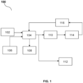
- FIG. 1 of the accompanying drawings shows a system block diagram of a vehicle load regulating system 100.
- the system 100 comprises a sensing module 102 and a processing unit 104.
- the sensing module 102 is operable to measure an onboard loading data of a motor vehicle.
- the term "onboard loading data" shall refer to information relating to a vehicle load onboard a motor vehicle.
- the parameters may include amongst others, a weight of load, a movement of load, a location of load onboard a motor, but not limited thereto.
- the system 100 may further comprises an accelerator sensor 106, to monitor vehicle speed when the motor vehicle is travelling.
- a centrifugal force acting on a horizontal axis of the motor vehicle may be measured using accelerator sensor 106 mounted on either side of the motor vehicle.
- a steering angle sensor (not shown) may be used to monitor a radius of a turning curve of the motor vehicle when the motor vehicle is travelling along a curved path.
- the system 100 may further comprises a human machine interface (HMI) module 108 for notifying an operator when a load condition of the motor vehicle reaches a pre-determined load limit, i.e. a vehicle overload condition.
- a pre-determined load limit may be a maximum vehicle load determined by factory configuration when manufacturing the motor vehicle.
- the HMI module 108 may include a display for displaying the load condition to the operator, or a voice activated function for notifying the load condition to the operator. In the event a vehicle overload condition is detection, the information may be stored in the processing unit 104 for future reference.
- the system 100 may be in communication with an engine system 114, a wheel speed sensor 1106, a throttle unit 110 and an anti-locking brake system (ABS) 112 of the motor vehicle.
- An advantage of the aforesaid configuration is to prevent vehicle overturning during operation of the motor vehicle, in the event poor vehicle load condition is determined by the processing unit 104.
- the transmission of information measured or monitored by the sensing module 102 to the processing unit 104 and to other sub-system or modules onboard the motor vehicle may be carried out by a communication network protocol, such as a vehicle bus.
- a communication network protocol such as a vehicle bus.
- suitable vehicle bus includes Controller Area Network (CAN), Local Interconnect Network (LIN) and FlexRay, but not limited thereto.
- the sensing module 102 may be embedded within a floor of a trailer compartment of a motor vehicle, for sensing an amount of pressure pressing against the floor of the trailer compartment, as shown in FIG. 3a-3b or FIG. 4a - 4b.
- the measurement of an amount of pressure pressing against the floor of the trailer compartment is transmitted to the processing unit 104, of which in response to the information on the pressure amount measured, the processing unit 104 determines a weight of load onboard the trailer compartment.
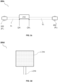
- the sensing module 102 comprises an air-filled tube pressure sensor 200a, as shown in FIG. 2a .
- the air-filled tube pressure sensor 200a comprises an air-filed tube sensor 204 and at least one pressure sensor 202, 202' on each end of the air-filled tube sensor 204.
- An example of such an air-filled tube sensor may be Continental's Pressure based Pedestrian Protection System PPS pSAT TM . Referring to FIG.
- FIG. 2b which shows a cross-section view of an embodiment 200b of an air-filled tube pressure sensor embedded within a floor of trailer compartment
- the air-filled tube pressure sensor 204 is arranged across an axis of the floor 210 of the trailer compartment, with a pressure sensor 202, 202' on each end of the air-filled tube pressure sensor 204.
- a buffer layer 208 may be arranged around the air-filled tube pressure sensor 204, for protection against wear and tear.
- An example of a suitable type of buffer layer may be soft foam.
- Additional mechanical plate 206 may be placed over the buffer layer 208 to conceal the buffer layer 208 from view.
- the sensing module 102 comprises force sensitive resistor (FSR) mats, which may be embedded within a floor of the trailer compartment.
- FSR force sensitive resistor
- a FSR mat provides a sensing area 214 for measuring or sensing pressure and sensing pins 216 for connecting to a circuitry.
- the sensing module 102 is further operable to monitor at least two contact points CP 1 , CP 2 at least partially pressing on sensing module 102.
- a load 212 has at least two contact points CP 1 , CP 2 pressing against a surface of the air-filled tube pressure sensor 204. Due to a weight of load 212 pressing against the air-filled tube pressure sensor 204, a volume of air, V 1 and V 2 on the left and right side of the load 212 changes.
- the information the at least two contact points CP 1 , CP 2 may be transmitted to the processing unit 104 for interpreted as location of load 212.
- a vehicle load condition is measured and be pre-stored in the processing unit 104.
- the load 212 moves from a first end of the trailer compartment to a second end of the trailer compartment, the pressure sensor 202' sense a decrease in pressure, while the pressure sensor 202 sense an increase in pressure. Consequently, the processing unit 104 interprets a change in location or a movement of the load 212 within the trailer compartment.
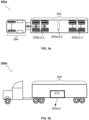
- FIG. 3a illustrates placement of sensing module 102 within a trailer compartment 302 of a motor vehicle 300a.
- one or more air-filled tube pressure sensors 200a-c may be strategically arranged on an area or a floor of the trailer compartment 302, such that vehicle load 212 or cargo which are loaded onto the floor of the trailer compartment 302 may be sense by the sensing module 102.
- the one or more air-filled tube pressure sensor 200a, 200b, 200c are placed in a front area of the trailer compartment 302, nearest to an operator compartment 304.
- FIG. 3b illustrates a side view of a motor vehicle 300b, with a load 212 placed within a trailer compartment 302 of the motor vehicle. Since the load 212 is placed over the air-filled tube sensor 200a', 200b', 200c', the aforesaid configuration enables measuring, monitoring and/or sensing of changes to vehicle load within the trailer compartment 302.
- the sensing module 102 comprises one or more FSR mats 200d, 200d' and 200d". Similar to the earlier embodiment disclosed herein, the FSR mats may be arranged at a front end of the trailer compartment 302, nearest to the operator compartment 304. The FSR mats may also be arranged in a middle section of the trailer compartment 302 and at a rear end of the trailer compartment 302. In the event a force is asserted on a subsequent FSR mate, i.e.
- a change of force from a first FSR mat to a force exerted on a second FSR mat is detected when the motor vehicle is accelerating or in an acceleration mode may be interpreted by the processing unit 104 as a change in location of load 212 or a movement of load 212 within the trailer compartment 302.
- FIG. 5 shows a load movement 500 within a commercial vehicle in accordance with an embodiment.
- a load 212 is placed near a front end of the trailer compartment 302, i.e. nearest to the operator compartment 304.
- a weight of load 212 may be measured by the sensing module 102.
- the sensing module 102 Presuming during acceleration of the motor vehicle, the load 212 moves from the front end of the trailer compartment 302 to a rear end of the trailer compartment 302, i.e. furthest end away from the operator compartment 304, a change in at least two contact points of the load 212 is thus monitored by the sensing module 102" which is embedded in a floor of the trailer compartment 302.
- This change contact points CP1, CP2 monitored by the sensing module 102 is in turn transmitted to the processing unit 104 to determine a movement of the load 212 within the trailer compartment 302.
- the processing unit 104 may comprises a computer-readable medium to execute a calculation algorithm (not shown in system diagram) stored on the processing unit 106.
- the calculation algorithm may be executed to determine a centrifugal force of the motor vehicle based on a set of parameters determined and/or monitored by the sensing module 102, such that the centrifugal force calculated may be used as a feedback mechanism to regulate a motion of the motor vehicle.
- the calculation algorithm may include formulas to calculate (1) a weight of load, (2) a location of load, (3) a frictional force of tires, (4) a centrifugal force and/or (5) velocity of a moving motor vehicle carrying a load.
- the FSR maximum load is greater than load measured by FSR.
- the intended load measured by FSR is 10000 N ( 10000N ⁇ 30000 N)
- Frictional force f S ⁇ * m * g
- the frictional force provides the centripetal force required for the trailer to avoid fishtailing or jack knifing.
- V min sqrt ⁇ * g * r
- the value of 'r' can be calculated from the steering angle sensor data and steering ratio of a motor vehicle in accordance with factory specification.
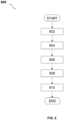
- FIG. 6 shows a flowchart 600 for a method of regulating vehicle load in accordance with an embodiment, at step 602, an onboard loading data of a motor vehicle is measured, by way of a sensing module.
- next step 604 the onboarding data measured by the sensing module is transmitted to a motor vehicle load regulating system, for example motor vehicle load regulating system 100 as disclosed herein.
- a processing unit of the motor vehicle load regulating system receives the onboard loading data and determines a centrifugal force in accordance with a set of parameters measured and/or calculated by a calculation algorithm stored on the processing unit, at step 608.
- the processing unit executes a feedback mechanism to the vehicle load regulating system, to regulate motion of the motor vehicle.
- further steps may be executed, including the step of transmitting the feedback mechanism to an anti-lock braking system.
- further steps may be executed, including the step of transmitting the feedback mechanism to a throttle control system.
- the set of parameters for calculating the centrifugal force may include a step of monitoring the onboard loading data relative to a change in an amount of pressure pressing on a floor of a trailer compartment of the motor vehicle.
- the amount of pressure measured, by way of the sensing module, may be transmitted to the processing unit for calculating or determining a weight of load withing the trailer compartment.
- the set of parameters may further comprise a step of monitoring the onboard loading data relative to at least two contact points pressing on the floor of the trailer compartment of the motor vehicle.
- the location of the at least two contact points pressing on the floor of the trailer compartment as monitored by the sensing module may be transmitted to the processing unit, such that a location of the load on the floor of the trailer compartment may be identified.
- the set of parameters may further comprise a step of identifying a movement of load within the trailer compartment of the motor vehicle, by measuring a weight of load and/or contact point of the load between a first sensing module and a subsequent sensing module.
- the processing unit may determine a frictional force of one or more tires of the motor vehicle.
- the frictional force of the commercial vehicle equates to the centripetal force of the commercial vehicle.
- An advantage of determining the frictional force avoid fishtailing or jack knifing when the motor vehicle is travelling at high speed, along a curved path.
- a radius of a turning curve of the motor vehicle may be monitored using a steering angle sensor.
- a notification may be issued to warn an operator a maximum load limit has reached.
- a vehicle load regulating system and method having the advantage of providing a feedback mechanism based upon a set of parameters measurable by at least one sensing module.
- a main advantage of the vehicle load regulating system and method is to prevent vehicle overturning due to overload, underload and/or uneven load of commercial vehicle.
- the set of parameters measured may be used to determine a frictional force of at least one tires, and a centrifugal force may be calculated based upon the set of parameters relative to the vehicle load measurable by the at least one sensing module.
- the effect of determining a centrifugal force achieves the objective of preventing fishtailing or jack-knifing accidents when the commercial vehicle is travelling at high speed on a curved road. While exemplary embodiments have been presented in the foregoing detailed description of the disclosure, it should be appreciated that a vast number of variation exist.
- Sensing module 104 Processing unit 106 Acceleration sensor 108 Human machine interface 110 Throttle control system 112 Anti - locking brake system (ABS) 114 Engine 116 Wheel speed sensor 200a Top view of sensing module (air-filled tube sensor) 202, 202' Pressure sensor 204 Air filled tube 200b Configuration for a floor of trailer compartment 206 Mechanical plate 208 Soft foam 210 Floor of trailer compartment 212 Load V Volume CP Contact point 200d Top view of sensing module (FSR) 214 Force sensitive resistor (FSR) mat 216 Sensing pins 300a Arrangement of sensing module comprising air-filled tube sensor 302 Trailer compartment 300b Side view of motor vehicle 400 Arrangement of sensing module comprising FSR mats 500 Side view of motor vehicle with load 600 Flowchart 602 Step of measuring onboard loading data 604 Transmitting onboard loading data to motor vehicle load system 606 Receiving onboard loading data measured 608 Determining centrifugal force 610 Executing feedback mechanism to regulate motion of motor vehicle
Landscapes
- Engineering & Computer Science (AREA)
- Mechanical Engineering (AREA)
- Transportation (AREA)
- Automation & Control Theory (AREA)
- Physics & Mathematics (AREA)
- Chemical & Material Sciences (AREA)
- Combustion & Propulsion (AREA)
- General Physics & Mathematics (AREA)
- Mathematical Physics (AREA)
- Human Computer Interaction (AREA)
- Electric Propulsion And Braking For Vehicles (AREA)
- Control Of Driving Devices And Active Controlling Of Vehicle (AREA)
- Valves And Accessory Devices For Braking Systems (AREA)
Abstract
Description
- This disclosure relates to a vehicle load regulating system, and specifically the vehicle load regulating system uses measurement of vehicle load and movement of vehicle to provide a feedback to the vehicle load regulating system.
- Commercial vehicles are used for transporting goods from one location to another location. Very often, safety issue is a major concern for commercial vehicle operators who are drowsy and fatigue from driving. In addition, hazards caused by overloading or uneven loading of cargo on commercial vehicle trucks may also endanger the operator.
- A known method for monitoring overload uses sensors to monitor height of commercial vehicle bed with respect to the suspension of the commercial vehicle, to determine overload or underload in real time. In such methods, the sensors are usually mounted on vehicle suspension system or air-spring system to monitor height of commercial vehicle.
- A main drawback of such overload monitoring system is that measurement of height of commercial vehicle bed which may be inaccurate due to uneven loading of truck bed. Other issues undetectable uneven distribution of load due to movement of cargo on commercial vehicle bed while traveling. In addition, effects of centrifugal force caused by commercial vehicle carrying overload traveling on highway curves, road bends or turns which may cause fishtailing or jack knifing cannot be addressed using conventional method of measurement of height of commercial vehicle bed per se. Load movement in commercial vehicle may also lead to fatal accidents vehicle is travelling at high speed, endangering both the operator of the commercial vehicle and other road users.
- There is therefore a need to provide a motor vehicle load regulating system that overcomes, or at least ameliorates, the problems described above. Furthermore, other desirable features and characteristics will become apparent from the subsequent detailed description and the appended claims, taking in conjunction with the accompanying drawings and this background of the disclosure.
- A purpose of this disclosure is to ameliorate the problem of vehicle overturning due to motor vehicle overloading or uneven loading by providing the subject-matter of the independent claims.
- Further purposes of this disclosure are set out in the accompanying dependent claims.
- The objective of this disclosure is solved by a method of regulating a vehicle load of a motor vehicle, the method comprising:
- measuring, by way of sensing module, an onboard loading data of a motor vehicle;
- transmitting, by way of a vehicle bus, the onboard loading data measured to a processing unit of a motor vehicle load regulating system;
- receiving, by way of a processing unit, the onboard loading data measured;
and
determining, by way of a processing unit, a centrifugal force of a motor vehicle relative to the onboard loading data measure,
characterized by that the method further comprises:
executing, by way of the processing unit, a feedback mechanism for regulating a motion of a motor vehicle in response to the centrifugal force determined. - An advantage of the above described aspect of this disclosure yields a method of regulating a vehicle load of a motor vehicle through calculation of a centrifugal force, by measuring various aspects of onboard load condition of the motor vehicle and providing the information to the vehicle load regulating system through a closed-loop feedback system, to avoid vehicle overturning. More advantageously, fishtailing or jack knifing may be avoided.
- Preferred is a method as described above or as described above as being preferred, in which the method further comprises:
monitoring, by way of the sensing module, the onboard loading data relative to a change in an amount of pressure pressing on a floor of a trailer compartment of the motor vehicle. - The advantage of the above aspect of this disclosure is to measure potential changes to pressure pressing against a floor of a trailer compartment of a motor vehicle, to achieve monitoring movement of vehicle load.
- Preferred is a method as described above or as described above as being preferred, in which the method further comprises:
determining, by way of the processing unit, a weight of load within the trailer compartment of the motor vehicle. - The advantage of the above aspect of this disclosure is to determine a weight of load within the trailer compartment in accordance with the change in pressure measured. More advantageously, the weight of load determined may be used as a parameter to determine whether the trailer is poorly loaded, for example overloaded, underloaded or unevenly loaded across a horizontal axis of the trailer compartment.
- Preferred is a method as described above or as described above as being preferred, in which the method further comprises:
monitoring, by way of the sensing module, the onboard loading data relative to at least two contact points pressing on the floor of the trailer compartment of the motor vehicle. - The advantage of the above aspect of this disclosure is to utilize the sensing module to monitor two or more contact points pressing on the floor of the trailer compartment, to monitor movement of vehicle load.
- Preferred is a method as described above or as described above as being preferred, in which the method further comprises:
determining, by way of the processing unit, a location of load within the trailer compartment of the motor vehicle. - The advantage of the above aspect of this disclosure is to determine or identify a location of load within the trailer compartment in response to the measurement of pressure contact points. Advantageously, this parameter assists to identify potential uneven loading of a commercial vehicle, especially when the commercial vehicle is travelling on road.
- Preferred is a method as described above or as described above as being preferred, in which the method further comprises:
in response to the weight of load determined, the method further comprises:
determining, by way of the processing unit, a frictional force of one or more tires of the motor vehicle. - The advantage of the above aspect of this disclosure is to calculate a frictional force of the commercial vehicle. The frictional force of the commercial vehicle equates to the centripetal force of the commercial vehicle. In this sense, the calculation of the frictional force is preferably done after the step of determining the weight of load. More advantageously, determining the frictional force avoid fishtailing or jack knifing when the commercial vehicle is travelling at high speed, along a curved path.
- Preferred is a method as described above or as described above as being preferred, in which the method further comprises:
monitoring, by way of a steering angle sensor, a radius of a turning curve of the motor vehicle. - The advantage of the above aspect of this disclosure is to monitor a radius of a turning curve of the commercial vehicle, such that this parameter may be used for determining effect of centrifugal force, to avoid vehicle overturning.
- Preferred is a method as described above or as described above as being preferred, in which the method further comprises:
notifying an operator of a load condition of the motor vehicle in response to measurement of load reaching a pre-determined load limit. - The advantage of the above aspect of this disclosure is to alert the operator in the event that an overload detection, i.e. a measured weight of load exceeds a predetermined axel limit.
- Preferred is a method as described above or as described above as being preferred, in which:
the feedback mechanism comprises: - the weight of load within the trailer compartment determined by the processing unit;
- the location of load within the trailer compartment determined by the processing unit; and
- the movement of the load within the trailer compartment determined by the processing unit;
- the frictional force of one or more tires of the motor vehicle; and the radius of a turning curve of the motor vehicle.
- The advantage of the above aspect of this disclosure is to determine a centrifugal force of the commercial truck, thereby achieving the objective of providing a negative feedback to the vehicle load regulating system.
- Preferred is a method as described above or as described above as being preferred, in which:
regulating the vehicle load of a motor vehicle in response to the centrifugal force determined further comprises: - transmitting, by way of the processing unit, the feedback mechanism to an anti-lock braking system;
- transmitting, by way of the processing unit, the feedback mechanism to a throttle control system,
- The advantage of the above aspect of this disclosure is to regulate the vehicle speed through an anti-locking brake system and/or a throttle system, to ensure safety of an operator of a commercial vehicle.
- The objective of this disclosure is solved by a motor vehicle load regulating system comprising:
- a sensing module operable to measure an onboard loading data of a motor vehicle; and
- a processing unit comprising:
an algorithm operable to determine a centrifugal force of a motor vehicle using the onboard loading data measured, - An advantage of the above described aspect of this disclosure yields a vehicle load regulating system, through calculation of a centrifugal force, by measuring various aspects of onboard load condition of the motor vehicle and providing the information to the vehicle load regulating system through a closed-loop feedback system, to avoid vehicle overturning. More advantageously, fishtailing or jack knifing may be avoided.
- Preferred is a system as described above or as described above as being preferred, in which:
the sensing module comprises at least one pressure sensor. - The advantage of the above aspect of this disclosure is to utilize one or more pressure sensors to measure or monitor changes in pressure, changes in location and/or movement of load within a trailer compartment of a commercial vehicle.
- Preferred is a system as described above or as described above as being preferred, in which:
the at least one pressure sensor is an air-filled tube sensor. - In one embodiment, the one or more pressure sensor may be an air-filed tube sensor which detects pressure. An example of such an air-filled tube sensor may be Continental's Pressure based Pedestrian Protection System PPS pSAT™.
- Preferred is a system as described above or as described above as being preferred, in which:
the at least one pressure sensor is a force sensitive resistor (FSR) mat. - In one embodiment, the one or more pressure sensor may be force sensitive resistor mat.
- Preferred is a system as described above or as described above as being preferred, in which:
the sensing module is embedded within a floor of a trailer compartment. - The advantage of the above aspect of this disclosure is to monitor a weight of load, a location of load and a movement of load of along a horizontal axis of a trailer compartment of a commercial vehicle, to determine a centrifugal force, thereby achieving the objective of avoiding fishtailing or jack knifing when travelling at high speed along a curved path.
- Preferred is a system as described above or as described above as being preferred, in which:
the onboard loading data comprises: - a change in an amount of pressure pressing on a floor of a trailer compartment of the motor vehicle;
- at least two contact points pressing on the floor of the trailer compartment of the motor vehicle; and
- a movement of load within the trailer compartment of the motor vehicle.
- The advantage of the above aspect of this disclosure is to determine a load condition of a commercial vehicle, specifically overload condition, underload condition or uneven load distribution across a floor of a trailer compartment of a commercial vehicle. The load condition may be used as parameters for calculation of centrifugal force when the commercial vehicle is travelling at high speed along a curved path. More advantageously, the centrifugal force calculated may be use as a feedback mechanism to regulate vehicle speed.
- Preferred is a system as described above or as described above as being preferred, in which:
the vehicle load regulating system further comprises: - an anti-lock braking system;
- a throttle control system,
- The advantage of the above aspect of this disclosure is to provide a vehicle load regulating system having a feedback mechanism to the anti-locking brake system and/or the throttle system, to ensure safety of an operator of a commercial vehicle.
- The objective of this disclosure is solved by a computer program comprising instructions to cause the system as disclosed herein to execute the steps as disclosed herein.
- An advantage of the above described aspect of this disclosure yields computer program product for calculation of a centrifugal force, by measuring various aspects of onboard load condition of the motor vehicle and providing the information to the vehicle load regulating system to avoid vehicle overturning. More advantageously, fishtailing or jack knifing may be avoided.
- The objective of this disclosure is solved by a computer-readable medium having stored thereon the computer program as disclosed herein.
- An advantage of the above described aspect of this disclosure yields computer program product for calculation of a centrifugal force, by measuring various aspects of onboard load condition of the motor vehicle and providing the information to the vehicle load regulating system. More advantageously, fishtailing or jack knifing may be avoided.
- Other objects and aspects of this disclosure will become apparent from the following description of embodiments with reference to the accompanying drawings in which:
-
FIG. 1 shows a system block diagram of a vehicle load regulating system in accordance with an embodiment. -
FIG. 2a-c shows a sensing module in accordance with an embodiment. -
FIG. 2d shows a sensing module in accordance with an embodiment. -
FIG. 3a - 3b shows a sensing module placement and simulation of a location of load within a commercial vehicle in accordance with an embodiment. -
FIG. 4 shows a sensing module placement within a commercial vehicle in accordance with an embodiment. -
FIG. 5 shows a detection of a movement of load within a commercial vehicle in accordance with an embodiment. -
FIG. 6 shows a flowchart for a method of regulating vehicle load in accordance with an embodiment. - In various embodiments described by reference to the above figures, like reference signs refer to like components in several perspective views and/or configurations.
- The following detailed description is merely exemplary in nature and is not intended to limit the disclosure or the application and uses of the disclosure. Furthermore, there is no intention to be bound by any theory presented in the preceding background of the disclosure or the following detailed description. It is the intent of this disclosure to present a vehicle load regulating system and method thereof.
- Hereinafter, the term "processing unit" used herein may broadly encompass a general-purpose processor, a central processing unit (CPU), a microprocessor, a digital signal processor (DSP), a controller, a microcontroller, a state machine, and so forth. Under some circumstances, a "processing unit" may refer to an application specific integrated circuit (ASIC), a programmable logic device (PLD), a field programmable gate array (FPGA), etc. The term "processing unit" may refer to a combination of processing devices, e.g., a combination of a DSP and a microprocessor, a plurality of microprocessors, one or more microprocessors in conjunction with a DSP core, or any other such configuration. The "processing unit" may include a memory, for loading a sequence of instruction, causing the "processing unit" to perform steps of actions. The term "memory" should be interpreted broadly to encompass any electronic component capable of storing electronic information. The term "memory" may refer to various types of processor-readable media such as random access memory (RAM), read-only memory (ROM), non-volatile random access memory (NVRAM), programmable read-only memory (PROM), erasable programmable read only memory (EPROM), electrically erasable PROM (EEPROM), flash memory, magnetic or optical data storage, registers, etc. "Memory" is said to be in electronic communication with a processor if the processor can read information from and/or write information to the memory. Memory that is integral to a processor is in electronic communication with the processor. Henceforth, the term "processing unit" may also be taken to encompass "system on chip" (SoC) which uses a single integrated circuit (IC) chip that contains multiple resources, computational units, processors and/or cores integrated on a single substrate. A single SOC may contain circuitry for digital, analog, mixed-signal, and radio-frequency functions, as well as any number of general purpose and/or specialized processors (digital signal processors, modem processors, video processors, etc.), memory blocks (e.g., ROM, RAM, Flash, etc.). Unless otherwise specifically stated, the "processing unit" is not limited to any specific combination of hardware circuitry and software, nor to any particular source for the instructions executed by the processing unit.
- The term "first", "second", "third" and the like used in the context of this disclosure may refer to modification of different elements in accordance with various exemplary embodiments, but not limited thereto. The expressions may be used to distinguish one element from another element, regardless of sequence of importance. By way of an example, "a first pressure sensor" and "a second pressure sensor" may indicate different pressure sensors regardless of order or importance. On a similar note, a first pressure sensor may be referred to as the second pressure sensor and vice versa without departing from the scope of this disclosure.
-
FIG. 1 of the accompanying drawings shows a system block diagram of a vehicleload regulating system 100. Thesystem 100 comprises asensing module 102 and aprocessing unit 104. Thesensing module 102 is operable to measure an onboard loading data of a motor vehicle. The term "onboard loading data" shall refer to information relating to a vehicle load onboard a motor vehicle. The parameters may include amongst others, a weight of load, a movement of load, a location of load onboard a motor, but not limited thereto. - The
system 100 may further comprises anaccelerator sensor 106, to monitor vehicle speed when the motor vehicle is travelling. A centrifugal force acting on a horizontal axis of the motor vehicle may be measured usingaccelerator sensor 106 mounted on either side of the motor vehicle. A steering angle sensor (not shown) may be used to monitor a radius of a turning curve of the motor vehicle when the motor vehicle is travelling along a curved path. - The
system 100 may further comprises a human machine interface (HMI)module 108 for notifying an operator when a load condition of the motor vehicle reaches a pre-determined load limit, i.e. a vehicle overload condition. The pre-determined load limit may be a maximum vehicle load determined by factory configuration when manufacturing the motor vehicle. TheHMI module 108 may include a display for displaying the load condition to the operator, or a voice activated function for notifying the load condition to the operator. In the event a vehicle overload condition is detection, the information may be stored in theprocessing unit 104 for future reference. - Optionally, the
system 100 may be in communication with anengine system 114, a wheel speed sensor 1106, athrottle unit 110 and an anti-locking brake system (ABS) 112 of the motor vehicle. An advantage of the aforesaid configuration is to prevent vehicle overturning during operation of the motor vehicle, in the event poor vehicle load condition is determined by theprocessing unit 104. The transmission of information measured or monitored by thesensing module 102 to theprocessing unit 104 and to other sub-system or modules onboard the motor vehicle may be carried out by a communication network protocol, such as a vehicle bus. Types of suitable vehicle bus includes Controller Area Network (CAN), Local Interconnect Network (LIN) and FlexRay, but not limited thereto. - The
sensing module 102 may be embedded within a floor of a trailer compartment of a motor vehicle, for sensing an amount of pressure pressing against the floor of the trailer compartment, as shown inFIG. 3a-3b or FIG. 4a - 4b. The measurement of an amount of pressure pressing against the floor of the trailer compartment is transmitted to theprocessing unit 104, of which in response to the information on the pressure amount measured, theprocessing unit 104 determines a weight of load onboard the trailer compartment. - In one embodiment, the
sensing module 102 comprises an air-filledtube pressure sensor 200a, as shown inFIG. 2a . The air-filledtube pressure sensor 200a comprises an air-filedtube sensor 204 and at least onepressure sensor 202, 202' on each end of the air-filledtube sensor 204. An example of such an air-filled tube sensor may be Continental's Pressure based Pedestrian Protection System PPS pSAT™. Referring toFIG. 2b which shows a cross-section view of anembodiment 200b of an air-filled tube pressure sensor embedded within a floor of trailer compartment, it can be seen that the air-filledtube pressure sensor 204 is arranged across an axis of thefloor 210 of the trailer compartment, with apressure sensor 202, 202' on each end of the air-filledtube pressure sensor 204. Optionally, abuffer layer 208 may be arranged around the air-filledtube pressure sensor 204, for protection against wear and tear. An example of a suitable type of buffer layer may be soft foam. Additionalmechanical plate 206 may be placed over thebuffer layer 208 to conceal thebuffer layer 208 from view. - In another embodiment as shown in
FIG. 2d , thesensing module 102 comprises force sensitive resistor (FSR) mats, which may be embedded within a floor of the trailer compartment. As shown onFIG. 2d , a FSR mat provides asensing area 214 for measuring or sensing pressure andsensing pins 216 for connecting to a circuitry. - The
sensing module 102 is further operable to monitor at least two contact points CP1, CP2 at least partially pressing onsensing module 102. By way of an example as shown inFIG. 2c , aload 212 has at least two contact points CP1, CP2 pressing against a surface of the air-filledtube pressure sensor 204. Due to a weight ofload 212 pressing against the air-filledtube pressure sensor 204, a volume of air, V1 and V2 on the left and right side of theload 212 changes. The information the at least two contact points CP1, CP2 may be transmitted to theprocessing unit 104 for interpreted as location ofload 212. - Referring to the embodiment shown in
FIG. 2c , a vehicle load condition is measured and be pre-stored in theprocessing unit 104. In response to monitoring a change in the at least two contact points, CP1, CP2 when the motor vehicle is accelerating or in an acceleration mode, theload 212 moves from a first end of the trailer compartment to a second end of the trailer compartment, the pressure sensor 202' sense a decrease in pressure, while thepressure sensor 202 sense an increase in pressure. Consequently, theprocessing unit 104 interprets a change in location or a movement of theload 212 within the trailer compartment. - For clarity,
FIG. 3a illustrates placement ofsensing module 102 within atrailer compartment 302 of amotor vehicle 300a. As seen inFIG. 3a , one or more air-filledtube pressure sensors 200a-c may be strategically arranged on an area or a floor of thetrailer compartment 302, such thatvehicle load 212 or cargo which are loaded onto the floor of thetrailer compartment 302 may be sense by thesensing module 102. In this exemplary embodiment, the one or more air-filledtube pressure sensor trailer compartment 302, nearest to anoperator compartment 304. One or more air-filledtube pressure sensor 200a', 200b', 200c' may be placed in a middle section of thetrailer compartment 302, and one or more air-filledtube pressure sensor 200a", 200b", 200c" may be placed at a rear section of thetrailer compartment 302.FIG. 3b illustrates a side view of amotor vehicle 300b, with aload 212 placed within atrailer compartment 302 of the motor vehicle. Since theload 212 is placed over the air-filledtube sensor 200a', 200b', 200c', the aforesaid configuration enables measuring, monitoring and/or sensing of changes to vehicle load within thetrailer compartment 302. - In another
embodiment 400 as shown inFIG. 4 , thesensing module 102 comprises one ormore FSR mats trailer compartment 302, nearest to theoperator compartment 304. The FSR mats may also be arranged in a middle section of thetrailer compartment 302 and at a rear end of thetrailer compartment 302. In the event a force is asserted on a subsequent FSR mate, i.e. a change of force from a first FSR mat to a force exerted on a second FSR mat is detected when the motor vehicle is accelerating or in an acceleration mode may be interpreted by theprocessing unit 104 as a change in location ofload 212 or a movement ofload 212 within thetrailer compartment 302. -
FIG. 5 shows aload movement 500 within a commercial vehicle in accordance with an embodiment. In this embodiment, aload 212 is placed near a front end of thetrailer compartment 302, i.e. nearest to theoperator compartment 304. A weight ofload 212 may be measured by thesensing module 102. Presuming during acceleration of the motor vehicle, theload 212 moves from the front end of thetrailer compartment 302 to a rear end of thetrailer compartment 302, i.e. furthest end away from theoperator compartment 304, a change in at least two contact points of theload 212 is thus monitored by thesensing module 102" which is embedded in a floor of thetrailer compartment 302. This change contact points CP1, CP2 monitored by thesensing module 102 is in turn transmitted to theprocessing unit 104 to determine a movement of theload 212 within thetrailer compartment 302. - The
processing unit 104 may comprises a computer-readable medium to execute a calculation algorithm (not shown in system diagram) stored on theprocessing unit 106. The calculation algorithm may be executed to determine a centrifugal force of the motor vehicle based on a set of parameters determined and/or monitored by thesensing module 102, such that the centrifugal force calculated may be used as a feedback mechanism to regulate a motion of the motor vehicle. - The calculation algorithm may include formulas to calculate (1) a weight of load, (2) a location of load, (3) a frictional force of tires, (4) a centrifugal force and/or (5) velocity of a moving motor vehicle carrying a load.
- In one embodiment, a weight of load within a
trailer compartment 302 may be determined or calculated but the calculation algorithm as follows:
- A = area of floor of trailer compartment
- g = acceleration due to gravity = 9.8m/s
- P = Pressure from individual pressure sensor
- n = number of sensors
- In one embodiment where air-tube filled sensors are used as sensing device of the
sensing module 102, a location of load within atrailer compartment 302 may be determined or calculated but the calculation algorithm as follows:
- CP 1& CP 2 are the position coordinates or contact points of the load
- P 1& P 2 are the pressure exerted on
sensors 202, 202' - r 1 = r 2 = r is the radius of air tube connecting the two pressure sensors
- In another embodiment where FSR mats are used as sensing device of the
sensing module 102, a total number of FSR mats required (N) may be calculated using the following formulas:
Formula F1,
- The FSR maximum load is greater than load measured by FSR.
- Spacing of FSR mat inside the floor of trailer compartment may be determined using formula F2,

- And formula F3,

N =Total number of FSR used - By way of an example, if a motor vehicle has an axle limit of 21 tonnes with a trailer compartment area of 3790m2, the axle load limit in Newtons = 205939.65 N. Max load of FSR = 30000 N. The maximum load of FSR may be obtained from specification of FSR component.
- The intended load measured by FSR is 10000 N ( 10000N < 30000 N)
- Total no of FSR required(N) = 21 (determined from formula F1)

- Spacing of FSR mats = 180, which means 1 sensor for 180m2 (Determined using formula F3)
- In both embodiment, a minimum velocity with respect to a centrifugal force and within a
trailer compartment 302 may be determined or calculated but the calculation algorithm as follows:
- µ = coefficent of friction
- m = mass of vehicle + load g = 9.8 m/s
- Therefore, the centrifugal force may be calculated by the calculation algorithm as follows:

- m = mass of vehicle + load
- V = Velocity of vehicle
- r = radius of curvature of turn
- Advantageously, the frictional force provides the centripetal force required for the trailer to avoid fishtailing or jack knifing.
- Consequently, the minimum velocity required to prevent the motor vehicle from fishtailing or jack knifing may be calculated by the calculation algorithm as follows:

- sqrt = √ function µ = coefficent of friction
- g = 9.8m/s
- r = radius of curvature of road
- In all of the above embodiments, the value of 'r' can be calculated from the steering angle sensor data and steering ratio of a motor vehicle in accordance with factory specification.
- Turning now to
FIG. 6 which shows aflowchart 600 for a method of regulating vehicle load in accordance with an embodiment, atstep 602, an onboard loading data of a motor vehicle is measured, by way of a sensing module. - In
next step 604, the onboarding data measured by the sensing module is transmitted to a motor vehicle load regulating system, for example motor vehicleload regulating system 100 as disclosed herein. Innest step 606, a processing unit of the motor vehicle load regulating system receives the onboard loading data and determines a centrifugal force in accordance with a set of parameters measured and/or calculated by a calculation algorithm stored on the processing unit, atstep 608. - In the
next step 610, the processing unit executes a feedback mechanism to the vehicle load regulating system, to regulate motion of the motor vehicle. - Optionally, in response to the centrifugal force determined by the processing unit, further steps may be executed, including the step of transmitting the feedback mechanism to an anti-lock braking system.
- Optionally, in response to the centrifugal force determined by the processing unit, further steps may be executed, including the step of transmitting the feedback mechanism to a throttle control system.
- Optionally, the set of parameters for calculating the centrifugal force may include a step of monitoring the onboard loading data relative to a change in an amount of pressure pressing on a floor of a trailer compartment of the motor vehicle. The amount of pressure measured, by way of the sensing module, may be transmitted to the processing unit for calculating or determining a weight of load withing the trailer compartment.
- Optionally, the set of parameters may further comprise a step of monitoring the onboard loading data relative to at least two contact points pressing on the floor of the trailer compartment of the motor vehicle. The location of the at least two contact points pressing on the floor of the trailer compartment as monitored by the sensing module may be transmitted to the processing unit, such that a location of the load on the floor of the trailer compartment may be identified.
- Optionally, the set of parameters may further comprise a step of identifying a movement of load within the trailer compartment of the motor vehicle, by measuring a weight of load and/or contact point of the load between a first sensing module and a subsequent sensing module.
- Optionally, in response to the weight of load determine, in a next step, the processing unit may determine a frictional force of one or more tires of the motor vehicle. The frictional force of the commercial vehicle equates to the centripetal force of the commercial vehicle. An advantage of determining the frictional force avoid fishtailing or jack knifing when the motor vehicle is travelling at high speed, along a curved path. Optionally, a radius of a turning curve of the motor vehicle may be monitored using a steering angle sensor.
- Optionally, in response to determining a load condition of the motor vehicle has reached a pre-determined load limit, a notification may be issued to warn an operator a maximum load limit has reached.
- Thus, it can be seen that a vehicle load regulating system and method having the advantage of providing a feedback mechanism based upon a set of parameters measurable by at least one sensing module has been provided. A main advantage of the vehicle load regulating system and method is to prevent vehicle overturning due to overload, underload and/or uneven load of commercial vehicle. Further thereto, the set of parameters measured may be used to determine a frictional force of at least one tires, and a centrifugal force may be calculated based upon the set of parameters relative to the vehicle load measurable by the at least one sensing module. The effect of determining a centrifugal force achieves the objective of preventing fishtailing or jack-knifing accidents when the commercial vehicle is travelling at high speed on a curved road. While exemplary embodiments have been presented in the foregoing detailed description of the disclosure, it should be appreciated that a vast number of variation exist.
- It should further be appreciated that the exemplary embodiments are only examples, and are not intended to limit the scope, applicability, operation or configuration of the disclosure in any way. Rather, the foregoing detailed description will provide those skilled in the art with a convenient road map for implementing an exemplary embodiment of the disclosure, it being understood that various changes may be made in the function and arrangement of elements and method of operation described in the exemplary embodiment without departing from the scope of the disclosure as set forth in the appended claims.
-
100 Vehicle load regulating system 102 Sensing module 104 Processing unit 106 Acceleration sensor 108 Human machine interface 110 Throttle control system 112 Anti - locking brake system (ABS) 114 Engine 116 Wheel speed sensor 200a Top view of sensing module (air-filled tube sensor) 202, 202' Pressure sensor 204 Air filled tube 200b Configuration for a floor of trailer compartment 206 Mechanical plate 208 Soft foam 210 Floor of trailer compartment 212 Load V Volume CP Contact point 200d Top view of sensing module (FSR) 214 Force sensitive resistor (FSR) mat 216 Sensing pins 300a Arrangement of sensing module comprising air-filled tube sensor 302 Trailer compartment 300b Side view of motor vehicle 400 Arrangement of sensing module comprising FSR mats 500 Side view of motor vehicle with load 600 Flowchart 602 Step of measuring onboard loading data 604 Transmitting onboard loading data to motor vehicle load system 606 Receiving onboard loading data measured 608 Determining centrifugal force 610 Executing feedback mechanism to regulate motion of motor vehicle
the processing unit is further operable to execute a feedback mechanism to a vehicle regulating to regulate a motion of a motor vehicle.
Claims (20)
- A method (600) of regulating a vehicle load of a motor vehicle, the method comprising:measuring (602), by way of a sensing module (102), an onboard loading data of a motor vehicle;transmitting (604), by way of a vehicle bus, the onboard loading data measured to a processing unit of a motor vehicle load regulating system;receiving (606), by way of a processing unit (104), the onboard loading data measured; anddetermining (608), by way of a processing unit (104), a centrifugal force of a motor vehicle relative to the onboard loading data measure, characterized by that the method further comprises:executing (610), by way of the processing unit (104), a feedback mechanism for regulating a motion of a motor vehicle in response to the centrifugal force determined.
- The method (600) according to claim 1, further comprising:
monitoring, by way of the sensing module (102), the onboard loading data relative to a change in an amount of pressure pressing on a floor of a trailer compartment (302) of the motor vehicle. - The method (600) according to claim 2, further comprising:
determining, by way of the processing unit (104), a weight of load within the trailer compartment (302) of the motor vehicle. - The method (600) according to claims 1 - 3, further comprising:
monitoring, by way of the sensing module (102), the onboard loading data relative to at least two contact points pressing on the floor of the trailer compartment (302) of the motor vehicle. - The method (600) according to claims 1 - 4, further comprising:
determining, by way of the processing unit (104), a location of load within the trailer compartment (302) of the motor vehicle. - The method (600) according to claims 1 - 5, further comprising:
identifying, by way of the sensing module (102), a movement of load within the trailer compartment (302) of the motor vehicle. - The method (600) according to claims 1 - 3, wherein in response to the weight of load determined, the method further comprises:
determining, by way of the processing unit (104), a frictional force of one or more tires of the motor vehicle. - The method (600) according to claims 1 - 7, further comprising:
monitoring, by way of a steering angle sensor, a radius of a turning curve of the motor vehicle. - The method (600) according to any one of the preceding claims, further comprising:
notifying, by way of a human-machine-interface module (108), an operator of a load condition of the motor vehicle in response to measurement of load reaching a pre-determined load limit. - The method (600) according to any one of the preceding claims, wherein the feedback mechanism comprises:the weight of load within the trailer compartment (302) determined by the processing unit (104);the location of load within the trailer compartment (302) determined by the processing unit (104);the movement of the load within the trailer compartment (302) determined by the processing unit (104);the frictional force of one or more tires of the motor vehicle; andthe radius of a turning curve of the motor vehicle.
- The method (600) according to any one of the preceding claims, wherein regulating the motion of a motor vehicle in response to the centrifugal force (fC ) determined further comprises:transmitting, by way of the processing unit (104), the feedback mechanism to an anti-lock braking system (112);transmitting, by way of the processing unit (104), the feedback mechanism to a throttle control system (110),or combination thereof.
- A motor vehicle load regulating system (100) comprising:a sensing module (102) operable to measure an onboard loading data of a motor vehicle; anda processing unit (104) comprising:
an algorithm operable to determine a centrifugal force (fC ) of amotor vehicle using the onboard loading data measured, characterized in that:
the processing unit (104) is further operable to execute a feedback mechanism to a vehicle load regulating system (100) to regulate a motion of a motor vehicle. - The system (100) according to claim 12, wherein
the sensing module (102) comprises at least one pressure sensor. - The system (100) according to claim 13, wherein
the at least one pressure sensor is an air-filled tube sensor (200a). - The system (100) according to claim 13, wherein
the at least one pressure sensor is a force sensitive resistor (FSR) mat (214). - The system (100) according to claims 12 to 15, wherein
the sensing module (102) is embedded within a floor (210) of a trailer compartment (302). - The system (100) according to claim 12, wherein the onboard loading data comprises:a change in an amount of pressure pressing on a floor (210) of a trailer compartment (302) of the motor vehicle;at least two contact points pressing on the floor (210) of the trailer compartment (302) of the motor vehicle; anda movement of load within the trailer compartment (302) of the motor vehicle.
- The system (100) according to any one of the preceding claims, wherein the vehicle load regulating system further comprises:an anti-lock braking system (112);a throttle control system (110),or combination thereof.
- A computer program comprising instructions to cause the system of claims 12 to 18 to execute the steps of claims 1 to 11.
- A computer-readable medium having stored thereon the computer program of claim 20.
Applications Claiming Priority (1)
| Application Number | Priority Date | Filing Date | Title |
|---|---|---|---|
| GB2210999.5A GB2620962A (en) | 2022-07-28 | 2022-07-28 | Vehicle load regulating system and method thereof |
Publications (1)
| Publication Number | Publication Date |
|---|---|
| EP4311698A1 true EP4311698A1 (en) | 2024-01-31 |
Family
ID=84540737
Family Applications (1)
| Application Number | Title | Priority Date | Filing Date |
|---|---|---|---|
| EP23187721.8A Pending EP4311698A1 (en) | 2022-07-28 | 2023-07-26 | Vehicle load regulating system and method thereof |
Country Status (3)
| Country | Link |
|---|---|
| US (1) | US20240034303A1 (en) |
| EP (1) | EP4311698A1 (en) |
| GB (1) | GB2620962A (en) |
Families Citing this family (3)
| Publication number | Priority date | Publication date | Assignee | Title |
|---|---|---|---|---|
| US12337852B2 (en) * | 2023-06-12 | 2025-06-24 | Ford Global Technologies, Llc | Vehicle load balancing systems and methods |
| AU2024326507A1 (en) * | 2023-08-23 | 2026-04-09 | North Carolina State University | Cargo container system and methods of using same |
| US20250384395A1 (en) * | 2024-06-13 | 2025-12-18 | PAR Excellence Systems, Inc. | Lightning controller |
Citations (7)
| Publication number | Priority date | Publication date | Assignee | Title |
|---|---|---|---|---|
| EP2159122A2 (en) * | 2008-06-05 | 2010-03-03 | Efkon Germany GmbH | Method and system for simultaneous vehicle and driving profile monitoring |
| DE102009013647A1 (en) * | 2009-03-17 | 2010-09-23 | Continental Automotive Gmbh | Lorry chassis regulating method, involves arranging spring and/or damping devices at axle arm, and controlling spring and/or damping devices against centrifugal force for supporting spring against chassis frame |
| DE102014009066A1 (en) * | 2013-11-29 | 2015-06-03 | Mando Corporation | Device and method for controlling the speed of a vehicle |
| DE102017114214A1 (en) * | 2017-06-27 | 2018-12-27 | Brose Fahrzeugteile Gmbh & Co. Kommanditgesellschaft, Bamberg | Vehicle trailer assembly and vehicle combination |
| EP3709240A1 (en) * | 2019-03-13 | 2020-09-16 | Ford Global Technologies, LLC | Methods for controlling weight distribution for cargo transportation |
| US20200324811A1 (en) * | 2017-11-06 | 2020-10-15 | Isuzu Motors Limited | Steering control device, steering control method, and recording medium |
| CN112238854A (en) * | 2019-07-16 | 2021-01-19 | 康明斯公司 | System and method for controlling vehicle speed to prevent or possibly prevent rollover |
Family Cites Families (5)
| Publication number | Priority date | Publication date | Assignee | Title |
|---|---|---|---|---|
| US20030058118A1 (en) * | 2001-05-15 | 2003-03-27 | Wilson Kitchener C. | Vehicle and vehicle tire monitoring system, apparatus and method |
| US7477972B2 (en) * | 2005-08-01 | 2009-01-13 | Delphi Technologies, Inc. | Rollover warning and detection method for transport vehicles |
| US9440632B2 (en) * | 2014-11-05 | 2016-09-13 | Bendix Commercial Vehicle Systems Llc | Method, controller and system for monitoring brake operation |
| DE102015013761A1 (en) * | 2015-10-23 | 2017-04-27 | Wabco Gmbh | Method for controlling brakes |
| US10427732B1 (en) * | 2018-09-13 | 2019-10-01 | James C. Carroll, Jr. | Articulated vehicle jackknife prevention system |
-
2022
- 2022-07-28 GB GB2210999.5A patent/GB2620962A/en not_active Withdrawn
-
2023
- 2023-07-26 EP EP23187721.8A patent/EP4311698A1/en active Pending
- 2023-07-27 US US18/227,005 patent/US20240034303A1/en active Pending
Patent Citations (7)
| Publication number | Priority date | Publication date | Assignee | Title |
|---|---|---|---|---|
| EP2159122A2 (en) * | 2008-06-05 | 2010-03-03 | Efkon Germany GmbH | Method and system for simultaneous vehicle and driving profile monitoring |
| DE102009013647A1 (en) * | 2009-03-17 | 2010-09-23 | Continental Automotive Gmbh | Lorry chassis regulating method, involves arranging spring and/or damping devices at axle arm, and controlling spring and/or damping devices against centrifugal force for supporting spring against chassis frame |
| DE102014009066A1 (en) * | 2013-11-29 | 2015-06-03 | Mando Corporation | Device and method for controlling the speed of a vehicle |
| DE102017114214A1 (en) * | 2017-06-27 | 2018-12-27 | Brose Fahrzeugteile Gmbh & Co. Kommanditgesellschaft, Bamberg | Vehicle trailer assembly and vehicle combination |
| US20200324811A1 (en) * | 2017-11-06 | 2020-10-15 | Isuzu Motors Limited | Steering control device, steering control method, and recording medium |
| EP3709240A1 (en) * | 2019-03-13 | 2020-09-16 | Ford Global Technologies, LLC | Methods for controlling weight distribution for cargo transportation |
| CN112238854A (en) * | 2019-07-16 | 2021-01-19 | 康明斯公司 | System and method for controlling vehicle speed to prevent or possibly prevent rollover |
Also Published As
| Publication number | Publication date |
|---|---|
| US20240034303A1 (en) | 2024-02-01 |
| GB202210999D0 (en) | 2022-09-14 |
| GB2620962A (en) | 2024-01-31 |
Similar Documents
| Publication | Publication Date | Title |
|---|---|---|
| US20240034303A1 (en) | Vehicle load regulating system and method thereof | |
| EP0786362B1 (en) | Method of and device for detecting tire pressure drop | |
| US9969370B2 (en) | Method and control device for warning a vehicle driver of a risk of the vehicle overturning | |
| US6725135B2 (en) | Vehicle stability operator feedback system | |
| US20020095253A1 (en) | Vehicle stability control system with tire sensor assembly | |
| CN111433054B (en) | Method and system for monitoring tire-related parameters during vehicle operation | |
| US20100131182A1 (en) | Systems and methods for measuring weight and weight distribution of a payload | |
| US20130151075A1 (en) | System and method for vehicle rollover prediction | |
| WO2002074593A1 (en) | Method and apparatus for vehicle rollover prediction and prevention | |
| JP2004359203A (en) | Vehicle condition monitoring device and contact surface condition quantity acquisition device | |
| CN119522175A (en) | Method for predicting the lateral dynamic stability behavior of a vehicle in its current vehicle configuration | |
| JP2004516983A (en) | System and method for determining vehicle loading | |
| JPWO2016039488A1 (en) | Connected vehicle fall prediction device and connected vehicle | |
| US6819980B2 (en) | Method for the avoidance of rollover phenomena in semitrailers | |
| KR20240046902A (en) | Method and apparatus for determining and characterizing roadway unevenness | |
| JP7137424B2 (en) | Driving characteristics evaluation method, driving characteristics evaluation program, and storage device | |
| JP2011247645A (en) | Method, apparatus and program for detecting inner pressure reduction of tire | |
| CN101585349A (en) | Method and system for vehicle rollover detection | |
| EP3943350B1 (en) | Apparatus and method for determining a road friction | |
| CN107600074A (en) | Vehicle speed measurement method and device | |
| CN106232439A (en) | For the method running electric brake system | |
| JP3992936B2 (en) | Vehicle rollover prevention device | |
| JP2004224262A (en) | Automatic brake control device | |
| US7912604B2 (en) | Method, apparatus and program for alarming abnormality in tire air-pressure | |
| KR20180113637A (en) | Method and system for the adaptation of the driving of a vehicle on a roadway in association with taking a curve |
Legal Events
| Date | Code | Title | Description |
|---|---|---|---|
| PUAI | Public reference made under article 153(3) epc to a published international application that has entered the european phase |
Free format text: ORIGINAL CODE: 0009012 |
|
| STAA | Information on the status of an ep patent application or granted ep patent |
Free format text: STATUS: THE APPLICATION HAS BEEN PUBLISHED |
|
| AK | Designated contracting states |
Kind code of ref document: A1 Designated state(s): AL AT BE BG CH CY CZ DE DK EE ES FI FR GB GR HR HU IE IS IT LI LT LU LV MC ME MK MT NL NO PL PT RO RS SE SI SK SM TR |
|
| RAP3 | Party data changed (applicant data changed or rights of an application transferred) |
Owner name: CONTINENTAL AUTOMOTIVE TECHNOLOGIES GMBH |
|
| STAA | Information on the status of an ep patent application or granted ep patent |
Free format text: STATUS: REQUEST FOR EXAMINATION WAS MADE |
|
| 17P | Request for examination filed |
Effective date: 20240731 |
|
| RBV | Designated contracting states (corrected) |
Designated state(s): AL AT BE BG CH CY CZ DE DK EE ES FI FR GB GR HR HU IE IS IT LI LT LU LV MC ME MK MT NL NO PL PT RO RS SE SI SK SM TR |
|
| STAA | Information on the status of an ep patent application or granted ep patent |
Free format text: STATUS: EXAMINATION IS IN PROGRESS |
|
| 17Q | First examination report despatched |
Effective date: 20250822 |
|
| RAP3 | Party data changed (applicant data changed or rights of an application transferred) |
Owner name: AUMOVIO GERMANY GMBH |
|
| GRAP | Despatch of communication of intention to grant a patent |
Free format text: ORIGINAL CODE: EPIDOSNIGR1 |
|
| STAA | Information on the status of an ep patent application or granted ep patent |
Free format text: STATUS: GRANT OF PATENT IS INTENDED |