EP4311693A1 - Pneumatic tire - Google Patents
Pneumatic tire Download PDFInfo
- Publication number
- EP4311693A1 EP4311693A1 EP23185458.9A EP23185458A EP4311693A1 EP 4311693 A1 EP4311693 A1 EP 4311693A1 EP 23185458 A EP23185458 A EP 23185458A EP 4311693 A1 EP4311693 A1 EP 4311693A1
- Authority
- EP
- European Patent Office
- Prior art keywords
- pneumatic tire
- groove
- sound absorbing
- absorbing member
- outer peripheral
- Prior art date
- Legal status (The legal status is an assumption and is not a legal conclusion. Google has not performed a legal analysis and makes no representation as to the accuracy of the status listed.)
- Withdrawn
Links
Images




Classifications
-
- B—PERFORMING OPERATIONS; TRANSPORTING
- B60—VEHICLES IN GENERAL
- B60C—VEHICLE TYRES; TYRE INFLATION; TYRE CHANGING; CONNECTING VALVES TO INFLATABLE ELASTIC BODIES IN GENERAL; DEVICES OR ARRANGEMENTS RELATED TO TYRES
- B60C19/00—Tyre parts or constructions not otherwise provided for
- B60C19/002—Noise damping elements provided in the tyre structure or attached thereto, e.g. in the tyre interior
Definitions
- the present invention relates to a pneumatic tire having a tread portion.
- Japanese Laid-Open Patent Publication No. 2019-108034 proposes a pneumatic tire in which protrusions and recesses are formed on the inward surface in the tire radial direction of a sound absorbing part to further reduce road noise.
- the loading time required to repair the puncture might be longer because the repair fluid is supplied through the sound absorber.
- the present invention has been made in view of the above circumstances, and a major object of the present invention is to provide a pneumatic tire in which a sponge-like sound absorbing member is basically provided on an inner surface of a tread portion and which can achieve both improved efficiency of puncture repair with a puncture repair material and noise performance.
- the present invention is directed to a pneumatic tire including a tread portion, wherein: a sponge-like sound absorbing member is firmly attached to an inner surface of the tread portion; the sound absorbing member has an outer peripheral surface facing outward in a tire radial direction; a plurality of grooves, and a plurality of land portions separated from each other by the plurality of grooves, are formed in the outer peripheral surface; and each of the plurality of grooves has an opening width at the outer peripheral surface larger than a groove bottom width of the groove in a cross-section thereof perpendicular to a longitudinal direction of the groove.
- the pneumatic tire according to the present invention can achieve both improved efficiency of puncture repair with a puncture repair material and noise performance.
- FIG. 1 is a cross-sectional view illustrating an embodiment of the pneumatic tire according to the present invention
- FIG. 1 is a tire meridian cross-sectional view of a pneumatic tire 1 according to the present embodiment in a standardized state, including the rotation axis of the pneumatic tire 1.
- the "standardized state” is a state where: the pneumatic tire 1 is fitted on a standardized rim and adjusted to a standardized internal pressure; and no load is applied to the pneumatic tire 1.
- dimensions and the like of components of the pneumatic tire 1 are values measured in the standardized state.
- the "standardized rim” is a rim that is defined for each tire by the standard, and is, for example, the "standard rim” in the JATMA standard, the “Design Rim” in the TRA standard, or the “Measuring Rim” in the ETRTO standard. If there is no standard system including a standard on which the pneumatic tire 1 is based, the "standardized rim” is a rim having the smallest rim diameter and having the smallest rim width, among rims to which the pneumatic tire 1 can be fitted and which do not cause air leakage.
- the "standardized internal pressure” is an air pressure that is defined for each tire by each standard, and is the “maximum air pressure” in the JATMA standard, the maximum value indicated in the table “TIRE LOAD LIMITS AT VARIOUS COLD INFLATION PRESSURES" in the TRA standard, or the "INFLATION PRESSURE” in the ETRTO standard. If there is no standard system including a standard on which the pneumatic tire 1 is based, the "standardized internal pressure” is an air pressure that is defined for each tire by the manufacturer or the like.
- the pneumatic tire 1 has a tread portion 2 that extends annularly, a pair of sidewall portions 3 that are provided on both sides in the tire axial direction of the tread portion 2, and bead portions 4 that are provided inward of the respective sidewall portions 3 in the tire radial direction.
- the tread portion 2 of the present embodiment has an outer surface 2a that forms a ground-contact surface that is brought into contact with a road surface during running.
- the sidewall portions 3 preferably extend inward in the tire radial direction from both sides in the tire axial direction of the tread portion 2.
- a buttress portion is provided between the tread portion 2 and each sidewall portion 3.
- Each bead portion 4 includes, for example, a portion that is brought into contact with a rim when the tire 1 is fitted onto the rim.
- the bead portion 4 of the present embodiment has a bead core 5 that extends annularly.
- the bead core 5 is formed of, for example, a steel wire.
- the pneumatic tire 1 of the present embodiment has a carcass 6 that extends from the tread portion 2 to the pair of bead portions 4 through the pair of sidewall portions 3, and a belt layer 7 that is provided outward of the carcass 6 in the tire radial direction in the tread portion 2.
- the pneumatic tire 1 may have, for example, a band layer (not shown) that is provided outward of the belt layer 7 in the tire radial direction.
- the carcass 6 preferably extends toroidally between the bead cores 5 of the pair of bead portions 4 through the tread portion 2 and the pair of sidewall portions 3.
- the carcass 6 includes at least one (e.g., one) carcass ply 6A.
- the carcass ply 6A of the present embodiment extends on and between the pair of bead portions 4 through the tread portion 2 and the pair of sidewall portions 3.
- the carcass ply 6A includes, for example, a body portion 6a that extends from the tread portion 2 to the bead core 5 of the bead portion 4 through the sidewall portion 3, and a turned-up portion 6b that is connected to the body portion 6a and turned up around the bead core 5 from the inside to the outside in the tire axial direction.
- a carcass 6 enhances the stiffness of the bead portion 4 and serves to improve the durability of the pneumatic tire 1.
- the belt layer 7 includes one or more (e.g., two) belt plies 7A and 7B.
- the two belt plies 7A and 7B include, for example, a first belt ply 7A located on the inner side in the tire radial direction, and a second belt ply 7B located outward of the first belt ply 7A in the tire radial direction.
- Such a belt layer 7 enhances the stiffness of the tread portion 2 and serves to improve the durability of the pneumatic tire 1.
- the pneumatic tire 1 has, for example, bead apexes 8 that are provided in the bead portions 4 and extend outward in the tire radial direction.
- each bead apex 8 extends outward in the tire radial direction from the bead core 5, between the body portion 6a and the turned-up portion 6b of the carcass 6.
- Such a bead apex 8 enhances the stiffness of the bead portion 4 and serves to improve the durability of the pneumatic tire 1.
- the pneumatic tire 1 of the present embodiment has a sponge-like sound absorbing member 9 that is provided on an inner surface 2b in the tire radial direction of the tread portion 2.
- the sound absorbing member 9 preferably has an outer peripheral surface 9a that faces outward in the tire radial direction, and an inner peripheral surface 9b that faces inward in the tire radial direction.
- the sound absorbing member 9 of the present embodiment is firmly attached at the outer peripheral surface 9a to the inner surface 2b of the tread portion 2.
- Such a sound absorbing member 9 can reduce the road noise of the pneumatic tire 1 and can improve the noise performance of the pneumatic tire 1.
- the sound absorbing member 9 may be firmly attached to the inner surface 2b by a sticky agent, an adhesive agent, a double-sided tape, or the like, or alternatively, may be fixed to the inner surface 2b by a sealant or the like applied to the inner surface 2b.
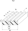
- FIG. 2 is a partial perspective view of the sound absorbing member 9.
- a plurality of grooves 10, and a plurality of land portions 11 separated from each other by the plurality of grooves 10, are formed in the outer peripheral surface 9a of the sound absorbing member 9 of the present embodiment.
- the plurality of land portions 11 are each firmly attached to the inner surface 2b of the tread portion 2 continuously along a longitudinal direction of the groove 10.
- such a sound absorbing member 9 allows a puncture repair material to be fed to a puncture area through the groove 10, thereby allowing reliable repair of the puncture area.
- spaces are formed between the sound absorbing member 9 and the tread portion 2 by the grooves 10, when heat is generated by the tread portion 2 during high speed running, heat accumulation by the sound absorbing member 9 can be reduced.
- FIG. 3 is an enlarged cross-sectional view perpendicular to the longitudinal direction of the groove 10.
- the plurality of grooves 10 of the present embodiment each have an opening width w1 at the outer peripheral surface 9a larger than a groove bottom width w2 of the groove 10 in a cross-section thereof perpendicular to the longitudinal direction of the groove 10.
- Such a sound absorbing member 9 can reduce the attached area thereof to the inner surface 2b of the tread portion 2, making it easy to feed the puncture repair material to a puncture area while maintaining good noise performance of the pneumatic tire 1. Therefore, the pneumatic tire 1 of the present embodiment can achieve both improved efficiency of puncture repair with the puncture repair material and noise performance.
- the attached area of the outer peripheral surface 9a to the inner surface 2b is 10% to 48% of the projected area of the sound absorbing member 9 onto the inner surface 2b.
- the attached area is not less than 10% of the projected area, the coming off of the sound absorbing member 9 can be suppressed, leading to an improvement in the durability of the pneumatic tire 1.
- the attached area is not greater than 48% of the projected area, the area of the inner surface 2b which is not in contact with the sound absorbing member 9 can be increased, so that efficiency of puncture repair with the puncture repair material can be improved.
- Each groove 10 has, for example, a trapezoidal cross-sectional shape in a cross-section thereof perpendicular to the longitudinal direction of the groove 10.
- Such a groove 10 can suppress a reduction in the volume of the sound absorbing member 9 while having an increased opening width w1 at the outer peripheral surface 9a, so that both improved efficiency of puncture repair with the puncture repair material and noise performance can be achieved.
- the opening widths w1 of the plurality of grooves 10 of the present embodiment are equal to each other in a cross-section thereof perpendicular to the longitudinal direction of the groove 10.
- the groove bottom widths w2 of the plurality of grooves 10 of the present embodiment are equal to each other in a cross-section thereof perpendicular to the longitudinal direction of the groove 10.
- Widths w3 at the outer peripheral surface 9a of the plurality of land portions 11 of the present embodiment are equal to each other in a cross-section thereof perpendicular to the longitudinal direction of the groove 10.
- the width w3 of each land portion 11 is preferably equal to the groove bottom width w2 of each groove 10.
- Maximum widths w4 of the plurality of land portions 11 of the present embodiment are equal to each other in a cross-section thereof perpendicular to the longitudinal direction of the groove 10.
- the maximum width w4 of each land portion 11 is preferably equal to the opening width w1 of each groove 10.
- each land portion 11 is preferably the same as the cross-sectional shape of each groove 10.
- both of the two portions can be used as the sound absorbing member 9, resulting in a reduction in manufacturing loss.
- the opening width w1 of each groove 10 is preferably 5 to 50 mm.
- the opening width w1 is not less than 5 mm, a space is reliably formed between the groove 10 and the inner surface 2b, so that efficiency of puncture repair of the pneumatic tire 1 with the puncture repair material can be improved.
- As the opening width w1 is not greater than 50 mm, a good noise reduction effect of the sound absorbing member 9 can be maintained, so that the noise performance of the pneumatic tire 1 can be improved.
- the groove bottom width w2 of each groove 10 is preferably 3 to 30 mm.
- the groove bottom width w2 is not less than 3 mm, the cross-sectional area of the groove 10 can be increased, so that efficiency of puncture repair with the puncture repair material can be improved.
- this case serves to maintain the strength of the sound absorbing member 9, so that the durability of the pneumatic tire 1 can be improved.
- the groove bottom width w2 is not greater than 30 mm, a good noise reduction effect of the sound absorbing member 9 can be maintained, so that the noise performance of the pneumatic tire 1 can be improved.
- Each groove 10 preferably has a groove depth d of 1 to 10 mm from the outer peripheral surface 9a.
- the groove depth d is not less than 1 mm, a space is reliably formed between the groove 10 and the inner surface 2b, so that efficiency of puncture repair with the puncture repair material can be improved.
- the groove depth d is preferably not less than 2 mm.
- the groove depth d is preferably not less than 3 mm.
- the groove depth d is not greater than 10 mm, a good noise reduction effect of the sound absorbing member 9 can be maintained, so that the noise performance of the pneumatic tire 1 can be improved.
- each groove 10 preferably has a pair of groove walls 10a.
- Each groove wall 10a of the present embodiment has a wall surface 10b that is inclined with respect to the outer peripheral surface 9a.
- An inclination angle ⁇ 1 between the wall surface 10b and the outer peripheral surface 9a is preferably 95 to 170°.
- Such a groove 10 has an obtuse inclination angle ⁇ 1, and thus can reduce a decrease in the strength of the land portion 11 and suppress the coming off of the sound absorbing member 9, so that the durability of the pneumatic tire 1 can be improved.
- Each groove 10 preferably has a bottom surface 10c that connects the pair of wall surfaces 10b.
- An inclination angle ⁇ 2 between the wall surface 10b and the bottom surface 10c of the present embodiment is equal to the inclination angle ⁇ 1 between the wall surface 10b and the outer peripheral surface 9a.
- the outer peripheral surface 9a and the bottom surface 10c can be formed so as to be parallel to each other, so that when the single material M (shown in FIG. 7 ) is cut along the outer peripheral surface 9a and thereby divided into two portions, it is useful to use both of the two portions as the sound absorbing member 9.
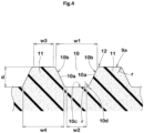
- FIG. 4 is an enlarged cross-sectional view perpendicular to the longitudinal direction of a groove 10 having chamfered portions 10d formed therein.
- a chamfered portion 10d may be formed at each of corner portions between the wall surfaces 10b and the bottom surface 10c.
- the chamfered portion 10d is formed, for example, in an arc shape in a cross-section thereof perpendicular to the longitudinal direction of the groove 10.
- Such a groove 10 can reduce a decrease in the strength of the land portion 11 and suppress the coming off of the sound absorbing member 9, so that the durability of the pneumatic tire 1 can be improved.
- a chamfered portion 12 having an arc shape is formed at each of corner portions between the wall surfaces 10b and the outer peripheral surface 9a of this embodiment.
- the chamfered portions 10d on the bottom surface 10c and the chamfered portions 12 on the outer peripheral surface 9a preferably have the same radius of curvature r.
- Such a land portion 11 maintains good strength and serves to suppress the coming off of the sound absorbing member 9.
- the opening width w1 of the groove 10 having the chamfered portions 12 formed therein is preferably defined as the minimum distance between the chamfered portions 12.
- the groove bottom width w2 of the groove 10 having the chamfered portions 10d formed therein is defined, for example, as the length of a straight portion between the chamfered portions 10d.
- the width w3 of the land portion 11 having the chamfered portions 12 formed therein is defined as the length of a straight portion between the chamfered portions 12, and the maximum width w4 of the land portion 11 having the chamfered portions 10d formed therein is defined as the maximum distance between the chamfered portions 10d.
- the radius of curvature r of each of the chamfered portions 10d on the bottom surface 10c and the chamfered portions 12 on the outer peripheral surface 9a is preferably 0.5 to 2 mm.
- the radius of curvature r is not less than 0.5 mm, the strength of the land portion 11 is maintained, and therefore, the coming off of the sound absorbing member 9 due to the deformation of the tread portion 2 during running can be suppressed.
- the radius of curvature r is not greater than 2 mm, a decrease in the attached area of the sound absorbing member 9 can be reduced, leading to suppression of the coming off of the sound absorbing member 9.
- FIG. 5 is a development of the sound absorbing member 9 of the present embodiment as viewed from above the outer peripheral surface 9a.
- each groove 10 of the present embodiment extends at an angle ⁇ 3 of less than 5° with respect to the tire circumferential direction. That is, each groove 10 can be said to extend in parallel to the tire circumferential direction.
- the sound absorbing member 9 has, for example, a pair of end surfaces 9c in the tire circumferential direction.
- Each groove 10 is preferably open at the pair of end surfaces 9c.
- Such a sound absorbing member 9 has both of a preferable attached area and a preferable strength, and can make the feeding of the puncture repair material more efficient in addition to suppression of the coming off of the sound absorbing member 9, so that both improved efficiency of puncture repair with the puncture repair material and durability of the pneumatic tire 1 can be achieved.
- FIG. 6 is a partial cross-sectional view of the pneumatic tire 1 taken at a tire equator C.
- the tire equator C is located at the center position between tread ground-contact ends Te on both sides in the tire axial direction shown in FIG. 1 .
- the tread ground-contact ends Te are outermost ground-contact positions in the tire axial direction when a standardized load is applied to the pneumatic tire 1 in the standardized state and the tire 1 is brought into contact with a flat surface at a camber angle of 0°.
- a tread ground-contact width TW between the tread ground-contact ends Te is the maximum width of a ground-contact surface when a standardized load is applied to the pneumatic tire 1 in the standardized state.
- the "standardized load” is a load that is defined for each tire by each standard, and is the "maximum load capacity" in the JATMA standard, the maximum value indicated in the table “TIRE LOAD LIMITS AT VARIOUS COLD INFLATION PRESSURES" in the TRA standard, or the "LOAD CAPACITY” in the ETRTO standard. If there is no standard system including a standard on which the pneumatic tire 1 is based, the "standardized load” is a load that is defined for each tire by the manufacturer or the like.
- a space L is formed between the pair of end surfaces 9c of the sound absorbing member 9 firmly attached to the inner surface 2b of the pneumatic tire 1 of the present embodiment.
- Such a sound absorbing member 9 allows the puncture repair material to be fed from the end surface 9c of the groove 10, so that efficiency of puncture repair with the puncture repair material can be improved.
- the space L between the end surfaces 9c is preferably 3 to 60 mm. As the space L is not less than 3 mm, the puncture repair material can be reliably fed from the end surface 9c of the groove 10. As the space L is not greater than 60 mm, non-uniformity in the tire circumferential direction can be reduced, leading to suppression of occurrence of vibrations, noise, and the like during high speed running.
- At least one (in the present embodiment, both) of the pair of end surfaces 9c has a tapered surface 9d whose height in the tire radial direction gradually becomes smaller.
- the tapered surface 9d of the present embodiment is formed in a flat surface shape.
- the tapered surface 9d may, for example, be formed in an arc shape. The coming off of such a sound absorbing member 9 from the end surface 9c, at which stress is concentrated during running, can be suppressed, leading to an improvement in the high speed durability of the pneumatic tire 1.
- the tapered surface 9d of the present embodiment is formed in a portion of the end surface 9c.
- the portion of the end surface 9c in which the tapered surface 9d is not formed preferably has a height H of 3 to 10 mm.
- damage to a sharp portion of the end surface 9c can be reduced, leading to an improvement in efficiency of the work of firmly attaching the sound absorbing member 9 to the inner surface 2b of the tread portion 2.
- the tapered surface 9d may be formed throughout the end surface 9c, for example.
- the tapered surface 9d is preferably inclined at angle ⁇ 4 of 30 to 80° with respect to the inner peripheral surface 9b.
- angle ⁇ 4 with respect to the inner peripheral surface 9b is not less than 30°, the effect of absorbing sound by the sound absorbing member 9 can be maintained at a satisfactory level.
- angle ⁇ 4 with respect to the inner peripheral surface 9b is not greater than 80°, the effect of suppressing the coming off of the sound absorbing member 9 from the end surface 9c can be reliably achieved.
- the single sound absorbing member 9 is firmly attached with the space L formed between the pair of end surfaces 9c in the tire circumferential direction.
- the pneumatic tire 1 of the present embodiment is not limited to such a mode.
- a plurality of sound absorbing members 9 may be firmly attached with spaces L formed in the tire circumferential direction. In that case, a space L is formed between the end surfaces 9c of adjacent sound absorbing members 9.
- the quantity, shape, and the like of the sound absorbing members 9 can be selected, depending on the purpose.
- a width W1 in the tire axial direction of the sound absorbing member 9 is preferably smaller than a width Wa in the tire axial direction of the belt layer 7.
- FIG. 7 is a schematic diagram showing the material M of the sound absorbing member 9, and FIG. 8 illustrates manufacturing of the sound absorbing member 9.
- the sound absorbing member 9 of the present embodiment is manufactured by cutting the single material M along the outer peripheral surface 9a.
- the material M is cut along the grooves 10 and the land portions 11, is then slid in the longitudinal direction of the groove 10, and thereby is separated into two sound absorbing members 9.
- the sound absorbing member 9 of the present embodiment is asymmetrical in the width direction thereof in a cross-section thereof perpendicular to the longitudinal direction of the groove 10. Therefore, as for the sound absorbing member 9 of the present embodiment, the separated two sound absorbing members 9 can be used as sound absorbing members 9 having the same shape, resulting in a further reduction in manufacturing loss.
- a sponge material is suitably used as the material M of the sound absorbing member 9.
- the sponge material include ether-based polyurethane, ester-based polyurethane, and polyethylene.
- Such a sound absorbing member 9 can reduce road noise while suppressing weight increase.
- the sponge material is not limited to such a mode, and may be, for example, a rubber-based sponge material.
- FIG. 9 is a development of a sound absorbing member 19 according to another embodiment as viewed from above an outer peripheral surface 19a thereof.
- a plurality of grooves 10, and a plurality of land portions 11 separated from each other by the plurality of grooves 10, are formed in the outer peripheral surface 19a of the sound absorbing member 19 of the present embodiment, as in the above-described sound absorbing member 9.
- the plurality of land portions 11 are each firmly attached to the inner surface 2b of the tread portion 2 (shown in FIG. 1 ) continuously along a longitudinal direction of the groove 10.
- Each groove 10 of the present embodiment extends at an angle ⁇ 5 of 5 to 90° with respect to the tire circumferential direction.
- the angle ⁇ 5 of the groove 10 is, for example, about 15 to 45°
- the groove 10 effectively contributes to high speed durability.
- the angle ⁇ 5 of the groove 10 is close to 90°, the groove 10 effectively contributes to feeding of the puncture repair material. Therefore, the angle ⁇ 5 of the groove 10 is preferably 45 to 60°.
- Such a sound absorbing member 19 serves to achieve both high speed durability and efficiency of puncture repair.
- Pneumatic tires having the basic structure in FIG. 1 were produced as test tires on the basis of specifications in Table 1 and Table 2. Noise performance, puncture repair time, and durability were evaluated using the produced test tires.
- the main common specifications and evaluation methods are as follows.
- a test tire having an air pressure adjusted to 250 kPa was mounted to a drum tester installed in an anechoic room, and the sound pressure was measured when running at 120 km/h in a state where a load of 6.6 kN was applied to the tire, and was evaluated as an index whose value was higher as a cavity resonance sound peak value was lower.
- the results are represented as indexes with the result of Comparative Example 1 being regarded as 100. A higher value indicates that the cavity resonance sound peak value is lower and the noise performance is better.
- a test tire was punctured by penetrating a 5-mm-diameter nail through a center area of the tread portion of the test tire, and the puncture was repaired with a puncture repair material using a commercially available puncture repair kit.
- the time taken for the puncture repair material to stop flowing out from the puncture area was measured, and was evaluated as an index whose value was higher as the time was shorter.
- the results are represented as indexes with the result of Comparative Example 1 being regarded as 100. A higher value indicates that the time taken for the puncture repair material to stop flowing out is shorter and the puncture repair is performed more efficiently.
- a test tire having an air pressure adjusted to 250 kPa was mounted to a drum tester, and the state of the internal structure of the tire was evaluated after running for 30000 km at 120 km/h in a state where a load of 6.6 kN was applied to the tire.
- the results are represented as indexes with the result of Comparative Example 1 being regarded as 100. A higher value indicates that the state of the internal structure of the tire is better and the durability is better.
- Example has a shorter puncture repair time while maintaining the same noise performance, as compared to that of each Comparative Example, and achieves both improved efficiency of puncture repair with the puncture repair material and noise performance.
- the pneumatic tire of each Example has better durability as compared to that of each Comparative Example.
- the present invention is as follows.
- a pneumatic tire including a tread portion, wherein
- each of the plurality of grooves has a trapezoidal cross-sectional shape in the cross-section.
- each of the plurality of grooves is 3 to 30 mm, and each of the grooves has a groove depth of 1 to 10 mm.
- each of the plurality of grooves extends at an angle of 5 to 90° with respect to a tire circumferential direction.
- each of the plurality of grooves extends at an angle of less than 5° with respect to a tire circumferential direction.
Landscapes
- Engineering & Computer Science (AREA)
- Mechanical Engineering (AREA)
- Tires In General (AREA)
Abstract
Description
- The present invention relates to a pneumatic tire having a tread portion.
- There has conventionally been a known pneumatic tire in which a sound absorbing part is provided on the inner surface of a tread portion in order to reduce road noise. For example,
Japanese Laid-Open Patent Publication No. 2019-108034 - However, according to the inventor's study, when repairing a puncture in an area where the sound absorber is adhered to using repair fluid, the loading time required to repair the puncture might be longer because the repair fluid is supplied through the sound absorber.
- The present invention has been made in view of the above circumstances, and a major object of the present invention is to provide a pneumatic tire in which a sponge-like sound absorbing member is basically provided on an inner surface of a tread portion and which can achieve both improved efficiency of puncture repair with a puncture repair material and noise performance.
- The present invention is directed to a pneumatic tire including a tread portion, wherein: a sponge-like sound absorbing member is firmly attached to an inner surface of the tread portion; the sound absorbing member has an outer peripheral surface facing outward in a tire radial direction; a plurality of grooves, and a plurality of land portions separated from each other by the plurality of grooves, are formed in the outer peripheral surface; and each of the plurality of grooves has an opening width at the outer peripheral surface larger than a groove bottom width of the groove in a cross-section thereof perpendicular to a longitudinal direction of the groove.
- As a result of having the above-described configuration, the pneumatic tire according to the present invention can achieve both improved efficiency of puncture repair with a puncture repair material and noise performance.
-
FIG. 1 is a cross-sectional view illustrating an embodiment of the pneumatic tire according to the present invention; -
FIG. 2 is a partial perspective view of a sound absorbing member; -
FIG. 3 is an enlarged cross-sectional view perpendicular to a longitudinal direction of a groove; -
FIG. 4 is an enlarged cross-sectional view perpendicular to a longitudinal direction of a groove having chamfered portions formed therein; -
FIG. 5 is a development of the sound absorbing member according to the embodiment as viewed from above an outer peripheral surface thereof; -
FIG. 6 is a partial cross-sectional view of the pneumatic tire; -
FIG. 7 is a schematic diagram showing the material of the sound absorbing member; -
FIG. 8 illustrates manufacturing of the sound absorbing member; and -
FIG. 9 is a development of a sound absorbing member according to another embodiment as viewed from above an outer peripheral surface thereof. - Hereinafter, an embodiment of the present invention will be described in detail with reference to the drawings.
-
FIG. 1 is a tire meridian cross-sectional view of apneumatic tire 1 according to the present embodiment in a standardized state, including the rotation axis of thepneumatic tire 1. Here, the "standardized state" is a state where: thepneumatic tire 1 is fitted on a standardized rim and adjusted to a standardized internal pressure; and no load is applied to thepneumatic tire 1. Hereinafter, unless otherwise specified, dimensions and the like of components of thepneumatic tire 1 are values measured in the standardized state. - If there is a standard system including a standard on which the
pneumatic tire 1 is based, the "standardized rim" is a rim that is defined for each tire by the standard, and is, for example, the "standard rim" in the JATMA standard, the "Design Rim" in the TRA standard, or the "Measuring Rim" in the ETRTO standard. If there is no standard system including a standard on which thepneumatic tire 1 is based, the "standardized rim" is a rim having the smallest rim diameter and having the smallest rim width, among rims to which thepneumatic tire 1 can be fitted and which do not cause air leakage. - If there is a standard system including a standard on which the
pneumatic tire 1 is based, the "standardized internal pressure" is an air pressure that is defined for each tire by each standard, and is the "maximum air pressure" in the JATMA standard, the maximum value indicated in the table "TIRE LOAD LIMITS AT VARIOUS COLD INFLATION PRESSURES" in the TRA standard, or the "INFLATION PRESSURE" in the ETRTO standard. If there is no standard system including a standard on which thepneumatic tire 1 is based, the "standardized internal pressure" is an air pressure that is defined for each tire by the manufacturer or the like. - As shown in
FIG. 1 , thepneumatic tire 1 according to the present embodiment has atread portion 2 that extends annularly, a pair ofsidewall portions 3 that are provided on both sides in the tire axial direction of thetread portion 2, and bead portions 4 that are provided inward of therespective sidewall portions 3 in the tire radial direction. - The
tread portion 2 of the present embodiment has anouter surface 2a that forms a ground-contact surface that is brought into contact with a road surface during running. Thesidewall portions 3 preferably extend inward in the tire radial direction from both sides in the tire axial direction of thetread portion 2. For example, a buttress portion is provided between thetread portion 2 and eachsidewall portion 3. Each bead portion 4 includes, for example, a portion that is brought into contact with a rim when thetire 1 is fitted onto the rim. The bead portion 4 of the present embodiment has abead core 5 that extends annularly. Thebead core 5 is formed of, for example, a steel wire. - The
pneumatic tire 1 of the present embodiment has acarcass 6 that extends from thetread portion 2 to the pair of bead portions 4 through the pair ofsidewall portions 3, and abelt layer 7 that is provided outward of thecarcass 6 in the tire radial direction in thetread portion 2. Thepneumatic tire 1 may have, for example, a band layer (not shown) that is provided outward of thebelt layer 7 in the tire radial direction. - The
carcass 6 preferably extends toroidally between thebead cores 5 of the pair of bead portions 4 through thetread portion 2 and the pair ofsidewall portions 3. Thecarcass 6 includes at least one (e.g., one)carcass ply 6A. Thecarcass ply 6A of the present embodiment extends on and between the pair of bead portions 4 through thetread portion 2 and the pair ofsidewall portions 3. - The
carcass ply 6A includes, for example, abody portion 6a that extends from thetread portion 2 to thebead core 5 of the bead portion 4 through thesidewall portion 3, and a turned-upportion 6b that is connected to thebody portion 6a and turned up around thebead core 5 from the inside to the outside in the tire axial direction. Such acarcass 6 enhances the stiffness of the bead portion 4 and serves to improve the durability of thepneumatic tire 1. - The
belt layer 7 includes one or more (e.g., two)belt plies belt plies first belt ply 7A located on the inner side in the tire radial direction, and asecond belt ply 7B located outward of thefirst belt ply 7A in the tire radial direction. Such abelt layer 7 enhances the stiffness of thetread portion 2 and serves to improve the durability of thepneumatic tire 1. - The
pneumatic tire 1 has, for example,bead apexes 8 that are provided in the bead portions 4 and extend outward in the tire radial direction. For example, eachbead apex 8 extends outward in the tire radial direction from thebead core 5, between thebody portion 6a and the turned-upportion 6b of thecarcass 6. Such abead apex 8 enhances the stiffness of the bead portion 4 and serves to improve the durability of thepneumatic tire 1. - The
pneumatic tire 1 of the present embodiment has a sponge-likesound absorbing member 9 that is provided on aninner surface 2b in the tire radial direction of thetread portion 2. Thesound absorbing member 9 preferably has an outerperipheral surface 9a that faces outward in the tire radial direction, and an innerperipheral surface 9b that faces inward in the tire radial direction. Thesound absorbing member 9 of the present embodiment is firmly attached at the outerperipheral surface 9a to theinner surface 2b of thetread portion 2. - Such a
sound absorbing member 9 can reduce the road noise of thepneumatic tire 1 and can improve the noise performance of thepneumatic tire 1. Here, thesound absorbing member 9 may be firmly attached to theinner surface 2b by a sticky agent, an adhesive agent, a double-sided tape, or the like, or alternatively, may be fixed to theinner surface 2b by a sealant or the like applied to theinner surface 2b. -
FIG. 2 is a partial perspective view of thesound absorbing member 9. As shown inFIG. 1 andFIG. 2 , a plurality ofgrooves 10, and a plurality ofland portions 11 separated from each other by the plurality ofgrooves 10, are formed in the outerperipheral surface 9a of thesound absorbing member 9 of the present embodiment. In the present embodiment, the plurality ofland portions 11 are each firmly attached to theinner surface 2b of thetread portion 2 continuously along a longitudinal direction of thegroove 10. - When the
pneumatic tire 1 has a puncture, such asound absorbing member 9 allows a puncture repair material to be fed to a puncture area through thegroove 10, thereby allowing reliable repair of the puncture area. In addition, since spaces are formed between thesound absorbing member 9 and thetread portion 2 by thegrooves 10, when heat is generated by thetread portion 2 during high speed running, heat accumulation by thesound absorbing member 9 can be reduced. -
FIG. 3 is an enlarged cross-sectional view perpendicular to the longitudinal direction of thegroove 10. As shown inFIG. 2 andFIG. 3 , the plurality ofgrooves 10 of the present embodiment each have an opening width w1 at the outerperipheral surface 9a larger than a groove bottom width w2 of thegroove 10 in a cross-section thereof perpendicular to the longitudinal direction of thegroove 10. - Such a
sound absorbing member 9 can reduce the attached area thereof to theinner surface 2b of thetread portion 2, making it easy to feed the puncture repair material to a puncture area while maintaining good noise performance of thepneumatic tire 1. Therefore, thepneumatic tire 1 of the present embodiment can achieve both improved efficiency of puncture repair with the puncture repair material and noise performance. - In a more preferable embodiment, the attached area of the outer
peripheral surface 9a to theinner surface 2b is 10% to 48% of the projected area of thesound absorbing member 9 onto theinner surface 2b. As the attached area is not less than 10% of the projected area, the coming off of thesound absorbing member 9 can be suppressed, leading to an improvement in the durability of thepneumatic tire 1. As the attached area is not greater than 48% of the projected area, the area of theinner surface 2b which is not in contact with thesound absorbing member 9 can be increased, so that efficiency of puncture repair with the puncture repair material can be improved. - Each
groove 10 has, for example, a trapezoidal cross-sectional shape in a cross-section thereof perpendicular to the longitudinal direction of thegroove 10. Such agroove 10 can suppress a reduction in the volume of thesound absorbing member 9 while having an increased opening width w1 at the outerperipheral surface 9a, so that both improved efficiency of puncture repair with the puncture repair material and noise performance can be achieved. - The opening widths w1 of the plurality of
grooves 10 of the present embodiment are equal to each other in a cross-section thereof perpendicular to the longitudinal direction of thegroove 10. In addition, the groove bottom widths w2 of the plurality ofgrooves 10 of the present embodiment are equal to each other in a cross-section thereof perpendicular to the longitudinal direction of thegroove 10. Such asound absorbing member 9 can reduce non-uniformity in a direction perpendicular to the longitudinal direction, and therefore can improve the noise performance of thepneumatic tire 1 in a well-balanced manner. - Widths w3 at the outer
peripheral surface 9a of the plurality ofland portions 11 of the present embodiment are equal to each other in a cross-section thereof perpendicular to the longitudinal direction of thegroove 10. The width w3 of eachland portion 11 is preferably equal to the groove bottom width w2 of eachgroove 10. Maximum widths w4 of the plurality ofland portions 11 of the present embodiment are equal to each other in a cross-section thereof perpendicular to the longitudinal direction of thegroove 10. The maximum width w4 of eachland portion 11 is preferably equal to the opening width w1 of eachgroove 10. - That is, the cross-sectional shape of each
land portion 11 is preferably the same as the cross-sectional shape of eachgroove 10. In the case of such asound absorbing member 9, when a single material M (shown inFIG. 7 ) is cut along the outerperipheral surface 9a and thereby divided into two portions, both of the two portions can be used as thesound absorbing member 9, resulting in a reduction in manufacturing loss. - The opening width w1 of each
groove 10 is preferably 5 to 50 mm. As the opening width w1 is not less than 5 mm, a space is reliably formed between thegroove 10 and theinner surface 2b, so that efficiency of puncture repair of thepneumatic tire 1 with the puncture repair material can be improved. As the opening width w1 is not greater than 50 mm, a good noise reduction effect of thesound absorbing member 9 can be maintained, so that the noise performance of thepneumatic tire 1 can be improved. - The groove bottom width w2 of each
groove 10 is preferably 3 to 30 mm. As the groove bottom width w2 is not less than 3 mm, the cross-sectional area of thegroove 10 can be increased, so that efficiency of puncture repair with the puncture repair material can be improved. In addition, in the case where the width w3 of eachland portion 11 is equal to the groove bottom width w2, this case serves to maintain the strength of thesound absorbing member 9, so that the durability of thepneumatic tire 1 can be improved. As the groove bottom width w2 is not greater than 30 mm, a good noise reduction effect of thesound absorbing member 9 can be maintained, so that the noise performance of thepneumatic tire 1 can be improved. - Each
groove 10 preferably has a groove depth d of 1 to 10 mm from the outerperipheral surface 9a. As the groove depth d is not less than 1 mm, a space is reliably formed between thegroove 10 and theinner surface 2b, so that efficiency of puncture repair with the puncture repair material can be improved. From such a viewpoint, in the case where the means for firmly attaching thesound absorbing member 9 is a sticky agent or a double-sided tape, the groove depth d is preferably not less than 2 mm. In the case where thesound absorbing member 9 is firmly attached by a sealant, the groove depth d is preferably not less than 3 mm. As the groove depth d is not greater than 10 mm, a good noise reduction effect of thesound absorbing member 9 can be maintained, so that the noise performance of thepneumatic tire 1 can be improved. - As shown in
FIG. 3 , eachgroove 10 preferably has a pair ofgroove walls 10a. Eachgroove wall 10a of the present embodiment has awall surface 10b that is inclined with respect to the outerperipheral surface 9a. An inclination angle θ1 between thewall surface 10b and the outerperipheral surface 9a is preferably 95 to 170°. Such agroove 10 has an obtuse inclination angle θ1, and thus can reduce a decrease in the strength of theland portion 11 and suppress the coming off of thesound absorbing member 9, so that the durability of thepneumatic tire 1 can be improved. - Each
groove 10 preferably has abottom surface 10c that connects the pair of wall surfaces 10b. An inclination angle θ2 between thewall surface 10b and thebottom surface 10c of the present embodiment is equal to the inclination angle θ1 between thewall surface 10b and the outerperipheral surface 9a. In such asound absorbing member 9, the outerperipheral surface 9a and thebottom surface 10c can be formed so as to be parallel to each other, so that when the single material M (shown inFIG. 7 ) is cut along the outerperipheral surface 9a and thereby divided into two portions, it is useful to use both of the two portions as thesound absorbing member 9. -
FIG. 4 is an enlarged cross-sectional view perpendicular to the longitudinal direction of agroove 10 having chamferedportions 10d formed therein. As shown inFIG. 4 , for example, a chamferedportion 10d may be formed at each of corner portions between the wall surfaces 10b and thebottom surface 10c. The chamferedportion 10d is formed, for example, in an arc shape in a cross-section thereof perpendicular to the longitudinal direction of thegroove 10. Such agroove 10 can reduce a decrease in the strength of theland portion 11 and suppress the coming off of thesound absorbing member 9, so that the durability of thepneumatic tire 1 can be improved. - A chamfered
portion 12 having an arc shape is formed at each of corner portions between the wall surfaces 10b and the outerperipheral surface 9a of this embodiment. Thechamfered portions 10d on thebottom surface 10c and thechamfered portions 12 on the outerperipheral surface 9a preferably have the same radius of curvature r. Such aland portion 11 maintains good strength and serves to suppress the coming off of thesound absorbing member 9. - The opening width w1 of the
groove 10 having the chamferedportions 12 formed therein is preferably defined as the minimum distance between thechamfered portions 12. In addition, the groove bottom width w2 of thegroove 10 having the chamferedportions 10d formed therein is defined, for example, as the length of a straight portion between thechamfered portions 10d. Similarly, preferably, the width w3 of theland portion 11 having the chamferedportions 12 formed therein is defined as the length of a straight portion between thechamfered portions 12, and the maximum width w4 of theland portion 11 having the chamferedportions 10d formed therein is defined as the maximum distance between thechamfered portions 10d. - The radius of curvature r of each of the chamfered
portions 10d on thebottom surface 10c and thechamfered portions 12 on the outerperipheral surface 9a is preferably 0.5 to 2 mm. As the radius of curvature r is not less than 0.5 mm, the strength of theland portion 11 is maintained, and therefore, the coming off of thesound absorbing member 9 due to the deformation of thetread portion 2 during running can be suppressed. As the radius of curvature r is not greater than 2 mm, a decrease in the attached area of thesound absorbing member 9 can be reduced, leading to suppression of the coming off of thesound absorbing member 9. -
FIG. 5 is a development of thesound absorbing member 9 of the present embodiment as viewed from above the outerperipheral surface 9a. As shown inFIG. 5 , eachgroove 10 of the present embodiment extends at an angle θ3 of less than 5° with respect to the tire circumferential direction. That is, eachgroove 10 can be said to extend in parallel to the tire circumferential direction. Thesound absorbing member 9 has, for example, a pair of end surfaces 9c in the tire circumferential direction. Eachgroove 10 is preferably open at the pair of end surfaces 9c. Such asound absorbing member 9 has both of a preferable attached area and a preferable strength, and can make the feeding of the puncture repair material more efficient in addition to suppression of the coming off of thesound absorbing member 9, so that both improved efficiency of puncture repair with the puncture repair material and durability of thepneumatic tire 1 can be achieved. -
FIG. 6 is a partial cross-sectional view of thepneumatic tire 1 taken at a tire equator C. Here, the tire equator C is located at the center position between tread ground-contact ends Te on both sides in the tire axial direction shown inFIG. 1 . The tread ground-contact ends Te are outermost ground-contact positions in the tire axial direction when a standardized load is applied to thepneumatic tire 1 in the standardized state and thetire 1 is brought into contact with a flat surface at a camber angle of 0°. In other words, a tread ground-contact width TW between the tread ground-contact ends Te is the maximum width of a ground-contact surface when a standardized load is applied to thepneumatic tire 1 in the standardized state. - If there is a standard system including a standard on which the
pneumatic tire 1 is based, the "standardized load" is a load that is defined for each tire by each standard, and is the "maximum load capacity" in the JATMA standard, the maximum value indicated in the table "TIRE LOAD LIMITS AT VARIOUS COLD INFLATION PRESSURES" in the TRA standard, or the "LOAD CAPACITY" in the ETRTO standard. If there is no standard system including a standard on which thepneumatic tire 1 is based, the "standardized load" is a load that is defined for each tire by the manufacturer or the like. - As shown in
FIG. 6 , a space L is formed between the pair of end surfaces 9c of thesound absorbing member 9 firmly attached to theinner surface 2b of thepneumatic tire 1 of the present embodiment. Such asound absorbing member 9 allows the puncture repair material to be fed from theend surface 9c of thegroove 10, so that efficiency of puncture repair with the puncture repair material can be improved. - The space L between the end surfaces 9c is preferably 3 to 60 mm. As the space L is not less than 3 mm, the puncture repair material can be reliably fed from the
end surface 9c of thegroove 10. As the space L is not greater than 60 mm, non-uniformity in the tire circumferential direction can be reduced, leading to suppression of occurrence of vibrations, noise, and the like during high speed running. - At least one (in the present embodiment, both) of the pair of
end surfaces 9c has a taperedsurface 9d whose height in the tire radial direction gradually becomes smaller. The taperedsurface 9d of the present embodiment is formed in a flat surface shape. The taperedsurface 9d may, for example, be formed in an arc shape. The coming off of such asound absorbing member 9 from theend surface 9c, at which stress is concentrated during running, can be suppressed, leading to an improvement in the high speed durability of thepneumatic tire 1. - The tapered
surface 9d of the present embodiment is formed in a portion of theend surface 9c. The portion of theend surface 9c in which the taperedsurface 9d is not formed preferably has a height H of 3 to 10 mm. In such asound absorbing member 9, damage to a sharp portion of theend surface 9c can be reduced, leading to an improvement in efficiency of the work of firmly attaching thesound absorbing member 9 to theinner surface 2b of thetread portion 2. It should be noted that the taperedsurface 9d may be formed throughout theend surface 9c, for example. - The tapered
surface 9d is preferably inclined at angle θ4 of 30 to 80° with respect to the innerperipheral surface 9b. As the angle θ4 with respect to the innerperipheral surface 9b is not less than 30°, the effect of absorbing sound by thesound absorbing member 9 can be maintained at a satisfactory level. As the angle θ4 with respect to the innerperipheral surface 9b is not greater than 80°, the effect of suppressing the coming off of thesound absorbing member 9 from theend surface 9c can be reliably achieved. - In the
pneumatic tire 1 of the present embodiment, the singlesound absorbing member 9 is firmly attached with the space L formed between the pair of end surfaces 9c in the tire circumferential direction. Thepneumatic tire 1 of the present embodiment is not limited to such a mode. Alternatively, in thepneumatic tire 1, a plurality ofsound absorbing members 9 may be firmly attached with spaces L formed in the tire circumferential direction. In that case, a space L is formed between the end surfaces 9c of adjacentsound absorbing members 9. For such apneumatic tire 1, the quantity, shape, and the like of thesound absorbing members 9 can be selected, depending on the purpose. - As shown in
FIG. 1 , a width W1 in the tire axial direction of thesound absorbing member 9 is preferably smaller than a width Wa in the tire axial direction of thebelt layer 7. With such asound absorbing member 9, an excessive increase in the weight of thepneumatic tire 1 is suppressed, leading to an improvement in the handling stability of thepneumatic tire 1. -
FIG. 7 is a schematic diagram showing the material M of thesound absorbing member 9, andFIG. 8 illustrates manufacturing of thesound absorbing member 9. As shown inFIG. 7 andFIG. 8 , thesound absorbing member 9 of the present embodiment is manufactured by cutting the single material M along the outerperipheral surface 9a. As for thesound absorbing member 9, for example, the material M is cut along thegrooves 10 and theland portions 11, is then slid in the longitudinal direction of thegroove 10, and thereby is separated into twosound absorbing members 9. - The
sound absorbing member 9 of the present embodiment is asymmetrical in the width direction thereof in a cross-section thereof perpendicular to the longitudinal direction of thegroove 10. Therefore, as for thesound absorbing member 9 of the present embodiment, the separated twosound absorbing members 9 can be used assound absorbing members 9 having the same shape, resulting in a further reduction in manufacturing loss. - A sponge material is suitably used as the material M of the
sound absorbing member 9. Examples of the sponge material include ether-based polyurethane, ester-based polyurethane, and polyethylene. Such asound absorbing member 9 can reduce road noise while suppressing weight increase. The sponge material is not limited to such a mode, and may be, for example, a rubber-based sponge material. -
FIG. 9 is a development of asound absorbing member 19 according to another embodiment as viewed from above an outerperipheral surface 19a thereof. As shown inFIG. 9 , a plurality ofgrooves 10, and a plurality ofland portions 11 separated from each other by the plurality ofgrooves 10, are formed in the outerperipheral surface 19a of thesound absorbing member 19 of the present embodiment, as in the above-describedsound absorbing member 9. In the present embodiment as well, the plurality ofland portions 11 are each firmly attached to theinner surface 2b of the tread portion 2 (shown inFIG. 1 ) continuously along a longitudinal direction of thegroove 10. - Each
groove 10 of the present embodiment extends at an angle θ5 of 5 to 90° with respect to the tire circumferential direction. In the case where the angle θ5 of thegroove 10 is, for example, about 15 to 45°, thegroove 10 effectively contributes to high speed durability. In the case where the angle θ5 of thegroove 10 is close to 90°, thegroove 10 effectively contributes to feeding of the puncture repair material. Therefore, the angle θ5 of thegroove 10 is preferably 45 to 60°. Such asound absorbing member 19 serves to achieve both high speed durability and efficiency of puncture repair. - Although the particularly preferred embodiments of the present invention have been described in detail above, the present invention is not limited to the above-described embodiments, and various modifications can be made to implement the present invention.
- Pneumatic tires having the basic structure in
FIG. 1 were produced as test tires on the basis of specifications in Table 1 and Table 2. Noise performance, puncture repair time, and durability were evaluated using the produced test tires. The main common specifications and evaluation methods are as follows. -
- Tire size: 215/55R17
- Width W1 of sound absorbing member: 120 mm
- Material M of sound absorbing member: ether-based polyurethane
- A test tire having an air pressure adjusted to 250 kPa was mounted to a drum tester installed in an anechoic room, and the sound pressure was measured when running at 120 km/h in a state where a load of 6.6 kN was applied to the tire, and was evaluated as an index whose value was higher as a cavity resonance sound peak value was lower. The results are represented as indexes with the result of Comparative Example 1 being regarded as 100. A higher value indicates that the cavity resonance sound peak value is lower and the noise performance is better.
- A test tire was punctured by penetrating a 5-mm-diameter nail through a center area of the tread portion of the test tire, and the puncture was repaired with a puncture repair material using a commercially available puncture repair kit. The time taken for the puncture repair material to stop flowing out from the puncture area was measured, and was evaluated as an index whose value was higher as the time was shorter. The results are represented as indexes with the result of Comparative Example 1 being regarded as 100. A higher value indicates that the time taken for the puncture repair material to stop flowing out is shorter and the puncture repair is performed more efficiently.
- A test tire having an air pressure adjusted to 250 kPa was mounted to a drum tester, and the state of the internal structure of the tire was evaluated after running for 30000 km at 120 km/h in a state where a load of 6.6 kN was applied to the tire. The results are represented as indexes with the result of Comparative Example 1 being regarded as 100. A higher value indicates that the state of the internal structure of the tire is better and the durability is better.
- The results of the evaluation are shown in Table 1 and Table 2.
[Table 1] Comp. Ex. 1 Comp. Ex. 2 Ex. 1 Ex. 2 Ex. 3 Ex. 4 Ex. 5 Ex. 6 Ex. 7 Height of sound absorbing member (mm) 22.5 25 25 25 25 25 25 25 25 Attached area/projected area (%) 100 50 37 11 48 32 47 45 23 Opening width w1 of groove (mm) - 5.0 8.5 39.0 5.5 6.5 30.0 6.2 16.5 Groove bottom width w2 of groove (mm) - 5.0 5.0 5.0 5.0 3.0 33.0 5.0 5.0 Groove depth d of groove (mm) - 3 3 3 3 3 3 1 10 Radius of curvature r of chamfered portion (mm) - 0 0 0 0 0 0 0 0 Inclination angle θ1 between wall surface and outer peripheral surface (°) - 90 120 170 95 120 120 120 120 Angles θ3 and θ5 of groove (°) - 0 0 0 0 0 0 0 0 Angle θ4 of tapered surface (°) 90 90 90 90 90 90 90 90 90 Space L of sound absorbing member (mm) 0 0 0 0 0 0 0 0 0 Noise performance (index) 100 95 100 100 100 100 100 100 100 Puncture repair time (index) 100 110 120 130 110 110 130 110 130 Durability (index) 100 110 120 120 110 120 110 110 120 [Table 2] Ex. 8 Ex. 9 Ex. 10 Ex. 11 Ex. 12 Ex. 13 Ex. 14 Ex. 15 Ex. 16 Ex. 17 Height of sound absorbing member (mm) 25 25 25 25 25 25 25 25 25 25 Attached area/projected area (%) 37 37 37 37 37 37 37 37 37 37 Opening width w1 of groove (mm) 8.5 8.5 8.5 8.5 8.5 8.5 8.5 8.5 8.5 8.5 Groove bottom width w2 of groove (mm) 5.0 5.0 5.0 5.0 5.0 5.0 5.0 5.0 5.0 5.0 Groove depth d of groove (mm) 3 3 3 3 3 3 3 3 3 3 Radius of curvature r of chamfered portion (mm) 0.5 2.0 0 0 0 0 0 0 0 0 Inclination angle θ1 between wall surface and outer peripheral surface (°) 120 120 120 120 120 120 120 120 120 120 Angles θ3 and θ5 of groove (°) 0 0 30 45 60 90 0 0 0 0 Angle θ4 of tapered surface (°) 90 90 90 90 90 90 30 80 90 90 Space L of sound absorbing member (mm) 0 0 0 0 0 0 0 0 3 60 Noise performance (index) 100 100 100 100 100 100 95 100 100 100 Puncture repair time (index) 120 120 120 120 120 120 120 120 130 140 - As a result of the evaluation, it is confirmed that the pneumatic tire of each
- Example has a shorter puncture repair time while maintaining the same noise performance, as compared to that of each Comparative Example, and achieves both improved efficiency of puncture repair with the puncture repair material and noise performance. In addition, it is confirmed that the pneumatic tire of each Example has better durability as compared to that of each Comparative Example.
- The present invention is as follows.
- A pneumatic tire including a tread portion, wherein
- a sponge-like sound absorbing member is firmly attached to an inner surface of the tread portion,
- the sound absorbing member has an outer peripheral surface facing outward in a tire radial direction,
- a plurality of grooves, and a plurality of land portions separated from each other by the plurality of grooves, are formed in the outer peripheral surface, and
- each of the plurality of grooves has an opening width at the outer peripheral surface larger than a groove bottom width of the groove in a cross-section thereof perpendicular to a longitudinal direction of the groove.
- The pneumatic tire according to
Present Invention 1, wherein an attached area of the outer peripheral surface to the inner surface is 10% to 48% of a projected area of the sound absorbing member onto the inner surface. - The pneumatic tire according to
Present Invention - The pneumatic tire according to any one of
Present Inventions 1 to 3, wherein - each of the plurality of grooves has a pair of groove walls,
- each of the pair of groove walls has a wall surface inclined with respect to the outer peripheral surface, and
- an inclination angle between the wall surface and the outer peripheral surface is 95 to 170°.
- The pneumatic tire according to Present Invention 4, wherein a chamfered portion is formed at each of corner portions between the wall surfaces and the outer peripheral surface.
- The pneumatic tire according to any one of
Present Inventions 1 to 5, wherein - the groove bottom widths of the plurality of grooves are equal to each other in the cross-section,
- widths at the outer peripheral surface of the plurality of land portions are equal to each other in the cross-section, and
- each of the widths is equal to the groove bottom width.
- The pneumatic tire according to any one of
Present Inventions 1 to 6, wherein the groove bottom width of each of the plurality of grooves is 3 to 30 mm, and each of the grooves has a groove depth of 1 to 10 mm. - The pneumatic tire according to any one of
Present Inventions 1 to 7, wherein each of the plurality of grooves extends at an angle of 5 to 90° with respect to a tire circumferential direction. - The pneumatic tire according to any one of
Present Inventions 1 to 7, wherein each of the plurality of grooves extends at an angle of less than 5° with respect to a tire circumferential direction. - The pneumatic tire according to any one of
Present Inventions 1 to 9, wherein - the sound absorbing member has a pair of end surfaces in the tire circumferential direction, and
- a space is formed between the pair of end surfaces.
Claims (10)
- A pneumatic tire (1) comprising a tread portion (2), whereina sponge-like sound absorbing member (9, 19) is firmly attached to an inner surface (2b) of the tread portion (2),the sound absorbing member (9, 19) has an outer peripheral surface (9a, 19a) facing outward in a tire radial direction,a plurality of grooves (10), and a plurality of land portions (11) separated from each other by the plurality of grooves (10), are formed in the outer peripheral surface (9a, 19a), andeach of the plurality of grooves (10) has an opening width (w1) at the outer peripheral surface (9a, 19a) larger than a groove bottom width (w2) of the groove (10) in a cross-section thereof perpendicular to a longitudinal direction of the groove (10).
- The pneumatic tire (1) according to claim 1, wherein an attached area of the outer peripheral surface (9a, 19a) to the inner surface (2b) is 10% to 48% of a projected area of the sound absorbing member (9, 19) onto the inner surface (2b).
- The pneumatic tire (1) according to claim 1 or 2, wherein each of the plurality of grooves (10) has a trapezoidal cross-sectional shape in the cross-section.
- The pneumatic tire (1) according to claims 1 to 3, whereineach of the plurality of grooves (10) has a pair of groove walls (10a),each of the pair of groove walls (10a) has a wall surface (10b) inclined with respect to the outer peripheral surface (9a, 19a), andan inclination angle (θ1) between the wall surface (10b) and the outer peripheral surface (9a, 19a) is 95 to 170°.
- The pneumatic tire (1) according to claim 4, wherein a chamfered portion (12) is formed at each of corner portions between the wall surfaces (10b) and the outer peripheral surface (9a, 19a).
- The pneumatic tire (1) according to claims 1 to 5, whereinthe groove bottom widths (w2) of the plurality of grooves (10) are equal to each other in the cross-section,widths (w3) at the outer peripheral surface (9a, 19a) of the plurality of land portions (11) are equal to each other in the cross-section, andeach of the widths (w3) is equal to the groove bottom width (w2).
- The pneumatic tire (1) according to claim 6, whereinthe groove bottom width (w2) of each of the plurality of grooves (10) is 3 to 30 mm, andeach of the grooves (10) has a groove depth (d) of 1 to 10 mm.
- The pneumatic tire (1) according to claims 1 7, wherein each of the plurality of grooves (10) extends at an angle (θ5) of 5 to 90° with respect to a tire circumferential direction.
- The pneumatic tire (1) according to claims 1 to 7, wherein each of the plurality of grooves (10) extends at an angle (θ3) of less than 5° with respect to a tire circumferential direction.
- The pneumatic tire (1) according to claim 9, whereinthe sound absorbing member (9) has a pair of end surfaces (9c) in the tire circumferential direction, anda space (L) is formed between the pair of end surfaces (9c).
Applications Claiming Priority (2)
| Application Number | Priority Date | Filing Date | Title |
|---|---|---|---|
| JP2022121202A JP2024018103A (en) | 2022-07-29 | 2022-07-29 | Pneumatic tire |
| JP2022179835A JP2024069056A (en) | 2022-11-09 | 2022-11-09 | Pneumatic tires |
Publications (1)
| Publication Number | Publication Date |
|---|---|
| EP4311693A1 true EP4311693A1 (en) | 2024-01-31 |
Family
ID=87281081
Family Applications (1)
| Application Number | Title | Priority Date | Filing Date |
|---|---|---|---|
| EP23185458.9A Withdrawn EP4311693A1 (en) | 2022-07-29 | 2023-07-14 | Pneumatic tire |
Country Status (2)
| Country | Link |
|---|---|
| US (1) | US20240034104A1 (en) |
| EP (1) | EP4311693A1 (en) |
Citations (5)
| Publication number | Priority date | Publication date | Assignee | Title |
|---|---|---|---|---|
| EP1795378A2 (en) * | 2005-12-08 | 2007-06-13 | Sumitomo Rubber Industries Ltd. | Pneumatic tire with noise damper |
| EP2123491A1 (en) * | 2008-05-09 | 2009-11-25 | The Yokohama Rubber Co., Ltd. | Tire noise reduction device |
| DE102011053686A1 (en) * | 2011-09-16 | 2013-03-21 | Continental Reifen Deutschland Gmbh | Radial type tubeless pneumatic tire for vehicle i.e. passenger car, has vibration damper arranged within circumference of tire on radial inner side of air-permeable inner layer, for damping vibrations along circumference |
| JP2019108034A (en) | 2017-12-19 | 2019-07-04 | 住友ゴム工業株式会社 | Pneumatic tire, and tire and rim assembly |
| CN112644231A (en) * | 2019-10-10 | 2021-04-13 | 建大工业股份有限公司 | Sound piece is inhaled to tire |
-
2023
- 2023-07-14 EP EP23185458.9A patent/EP4311693A1/en not_active Withdrawn
- 2023-07-28 US US18/227,358 patent/US20240034104A1/en not_active Abandoned
Patent Citations (5)
| Publication number | Priority date | Publication date | Assignee | Title |
|---|---|---|---|---|
| EP1795378A2 (en) * | 2005-12-08 | 2007-06-13 | Sumitomo Rubber Industries Ltd. | Pneumatic tire with noise damper |
| EP2123491A1 (en) * | 2008-05-09 | 2009-11-25 | The Yokohama Rubber Co., Ltd. | Tire noise reduction device |
| DE102011053686A1 (en) * | 2011-09-16 | 2013-03-21 | Continental Reifen Deutschland Gmbh | Radial type tubeless pneumatic tire for vehicle i.e. passenger car, has vibration damper arranged within circumference of tire on radial inner side of air-permeable inner layer, for damping vibrations along circumference |
| JP2019108034A (en) | 2017-12-19 | 2019-07-04 | 住友ゴム工業株式会社 | Pneumatic tire, and tire and rim assembly |
| CN112644231A (en) * | 2019-10-10 | 2021-04-13 | 建大工业股份有限公司 | Sound piece is inhaled to tire |
Also Published As
| Publication number | Publication date |
|---|---|
| US20240034104A1 (en) | 2024-02-01 |
Similar Documents
| Publication | Publication Date | Title |
|---|---|---|
| US10434823B2 (en) | Pneumatic radial tire for a passenger vehicle and method of using the same | |
| US6701986B2 (en) | Run-flat tire with tread reinforcing rubber layer | |
| EP2017092B1 (en) | Pneumatic tire set | |
| US10493803B2 (en) | Pneumatic radial tire for passenger vehicles | |
| US20210031570A1 (en) | Pneumatic Tire | |
| EP3960497A1 (en) | Tire | |
| EP1580030B1 (en) | Pneumatic tire | |
| EP1683654B1 (en) | Runflat tire | |
| JP2001071714A (en) | Pneumatic radial tire | |
| EP2602125B1 (en) | Pneumatic tire | |
| US20240034104A1 (en) | Pneumatic tire | |
| EP0914973B1 (en) | Pneumatic tyre for passenger cars and method of manufacture thereof | |
| JP2000351307A (en) | Run flat tire | |
| EP4311694A1 (en) | Pneumatic tire | |
| EP1642752B1 (en) | Radial tyre for motorcycle | |
| JP2024069056A (en) | Pneumatic tires | |
| JP3510816B2 (en) | Pneumatic radial tires for light trucks | |
| US20230015465A1 (en) | A noise improving tread | |
| EP4552865A1 (en) | Tire | |
| JP2024018104A (en) | Pneumatic tire | |
| EP4512640A1 (en) | Pneumatic tire | |
| US12558921B2 (en) | Tire | |
| EP3900954B1 (en) | Pneumatic tyre | |
| EP4434775A1 (en) | Tire assembly | |
| EP4578668A1 (en) | Tire |
Legal Events
| Date | Code | Title | Description |
|---|---|---|---|
| PUAI | Public reference made under article 153(3) epc to a published international application that has entered the european phase |
Free format text: ORIGINAL CODE: 0009012 |
|
| STAA | Information on the status of an ep patent application or granted ep patent |
Free format text: STATUS: THE APPLICATION HAS BEEN PUBLISHED |
|
| AK | Designated contracting states |
Kind code of ref document: A1 Designated state(s): AL AT BE BG CH CY CZ DE DK EE ES FI FR GB GR HR HU IE IS IT LI LT LU LV MC ME MK MT NL NO PL PT RO RS SE SI SK SM TR |
|
| P01 | Opt-out of the competence of the unified patent court (upc) registered |
Effective date: 20240327 |
|
| STAA | Information on the status of an ep patent application or granted ep patent |
Free format text: STATUS: REQUEST FOR EXAMINATION WAS MADE |
|
| 17P | Request for examination filed |
Effective date: 20240625 |
|
| RBV | Designated contracting states (corrected) |
Designated state(s): AL AT BE BG CH CY CZ DE DK EE ES FI FR GB GR HR HU IE IS IT LI LT LU LV MC ME MK MT NL NO PL PT RO RS SE SI SK SM TR |
|
| STAA | Information on the status of an ep patent application or granted ep patent |
Free format text: STATUS: EXAMINATION IS IN PROGRESS |
|
| 17Q | First examination report despatched |
Effective date: 20250506 |
|
| STAA | Information on the status of an ep patent application or granted ep patent |
Free format text: STATUS: THE APPLICATION HAS BEEN WITHDRAWN |
|
| 18W | Application withdrawn |
Effective date: 20250630 |