EP4311517A1 - Dental handpiece having an improved push button guidance - Google Patents
Dental handpiece having an improved push button guidance Download PDFInfo
- Publication number
- EP4311517A1 EP4311517A1 EP22195526.3A EP22195526A EP4311517A1 EP 4311517 A1 EP4311517 A1 EP 4311517A1 EP 22195526 A EP22195526 A EP 22195526A EP 4311517 A1 EP4311517 A1 EP 4311517A1
- Authority
- EP
- European Patent Office
- Prior art keywords
- push button
- head
- radial
- dental
- clamping means
- Prior art date
- Legal status (The legal status is an assumption and is not a legal conclusion. Google has not performed a legal analysis and makes no representation as to the accuracy of the status listed.)
- Granted
Links
Images




Classifications
-
- A—HUMAN NECESSITIES
- A61—MEDICAL OR VETERINARY SCIENCE; HYGIENE
- A61C—DENTISTRY; APPARATUS OR METHODS FOR ORAL OR DENTAL HYGIENE
- A61C1/00—Dental machines for boring or cutting ; General features of dental machines or apparatus, e.g. hand-piece design
- A61C1/08—Machine parts specially adapted for dentistry
- A61C1/14—Tool-holders, i.e. operating tool holders, e.g. burr holders
- A61C1/141—Tool-holders, i.e. operating tool holders, e.g. burr holders in an angled handpiece
-
- A—HUMAN NECESSITIES
- A61—MEDICAL OR VETERINARY SCIENCE; HYGIENE
- A61B—DIAGNOSIS; SURGERY; IDENTIFICATION
- A61B17/00—Surgical instruments, devices or methods
- A61B17/16—Instruments for performing osteoclasis; Drills or chisels for bones; Trepans
- A61B17/1613—Component parts
- A61B17/162—Chucks or tool parts which are to be held in a chuck
-
- A—HUMAN NECESSITIES
- A61—MEDICAL OR VETERINARY SCIENCE; HYGIENE
- A61C—DENTISTRY; APPARATUS OR METHODS FOR ORAL OR DENTAL HYGIENE
- A61C1/00—Dental machines for boring or cutting ; General features of dental machines or apparatus, e.g. hand-piece design
- A61C1/08—Machine parts specially adapted for dentistry
- A61C1/14—Tool-holders, i.e. operating tool holders, e.g. burr holders
- A61C1/142—Operating tool blocking means
- A61C1/144—Operating tool blocking means constricting the operating tool, e.g. chuck
Definitions
- the present invention relates to dental handpieces, in particular to the push button guidance of a dental handpiece for actuating a clamping mechanism for a dental drill.
- a dental handpiece is a handheld device for performing a variety of dental treatments which may require the use of various dental tools such as drills.
- the head of the dental handpiece is usually provided with a clamping mechanism such as a chuck that allows the dentist to change the dental tool in accordance with the intended dental treatment by means of a push button.
- the push button is movably held through a guide in the head of the dental handpiece.
- EP0639354A2 EP 1733696A1 , EP2959860A1 each disclosing a prior art dental handpiece.
- any excessive heating of the push button at the contact area with the clamping mechanism must be prevented in as much as possible.
- any excessive mechanical abrasion of the clamping jaws must be prevented in as much as possible.
- the size of the head should be reduced as much as possible so that it can easily reach spatially limited places in the oral cavity.
- the push button and the clamping mechanism must be operable in a reliable and easy manner.
- the objective of the present invention is to overcome one or more of the disadvantages of the prior art and provide a dental handpiece which is mechanically compact and easy to use.
- the dental handpiece of the present invention comprises: a head; a clamping means which is rotatably arranged within a bearing inside the head, and adapted for releasably clamping a dental drill, wherein the bearing has an inner race fixed to the clamping means and an outer race fixed to a housing of the head; a driving means for rotating the clamping means about an axial direction of the dental drill; a push button which is arranged movably in the head along the axial direction and configured to actuate the clamping means to release the dental drill; and a biasing means to move the push button away from the clamping means.
- the radial inner surface of the push button is arranged to contact and slide on the radial outer surface of the outer race which configures a guide for the moving push button along the axial direction, wherein the radial direction is perpendicular to axial direction of the dental drill.
- a radial clearance is arranged between the radial inner surface of the housing and a radial outer surface of the push button.
- Another major advantageous effect of the present invention is that the size of the head can be reduced. This can be explained as follows. Since the radial outer surface of the outer race which configures a guide for the moving push button along the axial direction, thereby the need for providing any separate guidance member can be avoided. This allows a compact mechanical configuration. The compact size of the head will also allow the dentist to easily reach spatially limited places in the oral cavity and to work more easily inside the oral cavity.
- the push button is operable in a more reliable and easy manner. This can be explained as follows: Since the radial outer surface of the outer race which configures a guide for the moving push button along the axial direction, the motion can be property aligned with the bearing surfaces, and thereby with the drill of the clamping mechanism. This enables a good alignment between the moving parts.
- the push button can be provided as a single piece member or a two-piece member.
- Fig. 1 shows a dental handpiece (1) according to an embodiment of the invention.
- dental handpiece (1) has a body (3) and a head (4).
- a dental drill (2) is detachably attached to the head (4).
- Fig. 2a shows an enlarged cross-sectional view of the head (4).
- the head (4) has a housing (5) which accommodates a clamping means (13).
- the clamping means (13) has a chuck (26) with resilient arms (27) for releasably clamping the dental drill (2).
- a hollow shaft (15) is rotatably arranged inside the head (4).
- the chuck (26) is fixed into the hollow shaft (15) to rotate with same.
- the dental handpiece (1) has a driving means such as a motor (not shown) for rotating the hollow shaft (15).
- the driving means is coupled to a driving shaft (32) as shown in Fig. 2a , that is rotatably held through a bearing (33) having an outer race (34), an inner race (35), multiple balls (36), and a retainer (37).
- the end of the driving shaft (32) has a crown gear (38) that meshes with a gear (16) on the hollow shaft (15).
- the hollow shaft (15) is rotatably held through a couple of bearings (19; 19') mounted into the housing (5).
- Each bearing (19;19') has an outer race (20) and inner race (21), multiple balls (22) and a retainer (23).
- the clamping means (13) has a ball (14), preferably made of ceramic material, which is axially movably arranged inside the rotatable hollow shaft (15) and in direct contact with the resilient arms (27) of the chuck (26).
- the ball (14) partly protrudes through an opening (17) in the upper end of the hollow shaft (15).
- the size of the opening (17) is smaller than the size of the ball (14) so that it is retained partly within the hollow shaft (15).
- the opening (17) has an annular stop edge (18) which restricts the outwards movement of that ball (14).
- the dental handpiece (1) has a push button (7) which is arranged in the head (4) and configured to contact, when pressed by a user, the partly protruding ball (14) and move the ball (14) downwardly in between the resilient arms (27) to flex the resilient arms (27) radially outwards and release the dental drill (2).
- the chuck (26) has two diametrically opposed cut-outs (28) in its upper portion to form the two resilient arms (27).
- a linear semi cylindrical channel is formed into the upper portion of the chuck (26) whose edges form two diametrically opposed contact points (27a) to contact the ball (14).
- the chuck (26) has a large diameter portion (29) and a small diameter portion (30).
- the dental drill (2) can be manually inserted only until the upper end of the large diameter portion (29).
- the resilient arms (27) are flexed through the ball (14), the dental drill (2) can be further inserted into the small diameter portion (30) until it abuts against the contact edge (31) (Burr stop).
- the resilient arms (27) are retracted, and the dental drill (2) is clamped in the small diameter portion (30) between the resilient arms (27).
- the resilient arms (27) also bias the ball (14) inside the rotatable hollow shaft (15) towards the opening (17). As shown in Fig.
- the pushbutton (7) has a cap (8), and a hat-shaped flange collar (9) arranged inside the cap (8) and fixed thereto.
- the hat-shaped flange collar (9) has a point like contact surface (10), preferably planar, for the ball (14).
- the pushbutton (7) has a biasing means such a spring (11), preferably a cone shaped spring (11) to move the push button (7) away and detach it from the ball (14).
- the point like contact surface (10) is not in contact with the ball (14) when the push button (7) is released.
- the contact surface (10) comes in point contact with the upper side of the ball (14) when the push button (7) is pressed downwards.
- Fig. 2c shows an enlarged view of the two-piece pushbutton (7) in Fig. 2a which is configured by the cap (8) and the hat-shaped Flange collar (9).
- Fig. 7a and Fig. 7b show the two-piece push button (7) in more detail.
- Fig. 2d shows an alternative embodiment, wherein the cap (9') is provided as a single piece instead of two separate pieces. All other features remain the same. Thereby the number of pieces can be further reduced.
- Fig. 7c and 7d show the single-piece push button (7) in more detail.
- a radial inner surface (7a) of the push button (7) is arranged to contact and slide on a radial outer surface (20a) of the outer race (20) which configures a guide (12) for the moving push button (7).
- the radial direction is perpendicular to the axial direction (A) of the dental drill (2).
- a radial clearance (s) is arranged between a radial inner surface (5b) of the housing (5) and a radial outer surface (7b) of the push button (7).
- the housing (5) has an internal thread (6) which receives a screw ring (24).
- the mounting flange of the upper bearing (19) is fixed to its mounting position through the screw ring (24).
- the screw ring (24) has a nose (25) which can be seen in Fig. 2d but not in Fig.2a .
- the cross-sectional views respectively in Fig. 2a and Fig. 2d are rotated about 90 degrees with respect to each other.
- the cross-section in Fig. 2a is along the line I-I as shown in Fig. 1 and the cross section in Fig. 2d is along the line II-II as shown in Fig. 1 .
- the nose (25) extends radially inwards and can abut from below against the claw (9a) of the hat-shaped flange collar (9) which extends radially outwards and prevents the push button (7) from disengaging from the housing (5).
- the hat-shaped flange collar (9) can be provided separately from or integrally with the cap (8;9'). In the former case an air gap (9b) is preferably formed underneath the cap (8) to improve thermal insulation as shown in Fig. 2a . Alternatively the air gap (9b) may be filled with a material that is a poor heat-conductor.
- the inner surface of the hat-shaped flange collar (9) slides on the outer surface of outer race (20) while being in contact with the latter which configures a guide (12) for the push button (7) movement.
- the nose (25) of the screw ring (24) is arranged above the claw (9a) of the hat-shaped flange collar (9).
- the hat-shaped flange collar (9) does not contact the inner radial surface of the screw ring (24).
- the housing (5) has a gap (5a) directly above the screw ring (24) and the nose (25), which allows the cap (8;9') to move upwards or downwards during the clamping/releasing operation.
- the screw ring (24) is entirely embedded/recessed inside the housing (5) and does not project outside the head (4). Thereby, the height of the head (4) can be reduced. Thereby also the diameter of the cap (8,9') can be increased so that the actuating pressure on the finger is reduced.
- the outer cylindrical surface of the cap (8;9') does not contact the inner surface of the housing (5) during its entire movement thanks to the sufficient radial clearance (S).
- guide (12) serves as a guiding contact surface for the up/down movement of the cap (8;9').
Landscapes
- Health & Medical Sciences (AREA)
- Oral & Maxillofacial Surgery (AREA)
- Life Sciences & Earth Sciences (AREA)
- Veterinary Medicine (AREA)
- Animal Behavior & Ethology (AREA)
- General Health & Medical Sciences (AREA)
- Public Health (AREA)
- Dentistry (AREA)
- Epidemiology (AREA)
- Surgery (AREA)
- Nuclear Medicine, Radiotherapy & Molecular Imaging (AREA)
- Orthopedic Medicine & Surgery (AREA)
- Engineering & Computer Science (AREA)
- Biomedical Technology (AREA)
- Heart & Thoracic Surgery (AREA)
- Medical Informatics (AREA)
- Molecular Biology (AREA)
- Dental Tools And Instruments Or Auxiliary Dental Instruments (AREA)
Abstract
Description
- The present invention relates to dental handpieces, in particular to the push button guidance of a dental handpiece for actuating a clamping mechanism for a dental drill.
- A dental handpiece is a handheld device for performing a variety of dental treatments which may require the use of various dental tools such as drills. The head of the dental handpiece is usually provided with a clamping mechanism such as a chuck that allows the dentist to change the dental tool in accordance with the intended dental treatment by means of a push button. The push button is movably held through a guide in the head of the dental handpiece.
- Reference is made to
EP0639354A2 ,EP 1733696A1 ,EP2959860A1 each disclosing a prior art dental handpiece. - There are certain design requirements that must be met by the dental handpiece to assure its proper operation. For example, any excessive heating of the push button at the contact area with the clamping mechanism must be prevented in as much as possible. For example, any excessive mechanical abrasion of the clamping jaws must be prevented in as much as possible. For example, the size of the head should be reduced as much as possible so that it can easily reach spatially limited places in the oral cavity. For example, the push button and the clamping mechanism must be operable in a reliable and easy manner.
- The objective of the present invention is to overcome one or more of the disadvantages of the prior art and provide a dental handpiece which is mechanically compact and easy to use.
- This objective has been achieved through the dental handpiece as defined in claim 1.
- The dental handpiece of the present invention comprises: a head; a clamping means which is rotatably arranged within a bearing inside the head, and adapted for releasably clamping a dental drill, wherein the bearing has an inner race fixed to the clamping means and an outer race fixed to a housing of the head; a driving means for rotating the clamping means about an axial direction of the dental drill; a push button which is arranged movably in the head along the axial direction and configured to actuate the clamping means to release the dental drill; and a biasing means to move the push button away from the clamping means. The radial inner surface of the push button is arranged to contact and slide on the radial outer surface of the outer race which configures a guide for the moving push button along the axial direction, wherein the radial direction is perpendicular to axial direction of the dental drill. A radial clearance is arranged between the radial inner surface of the housing and a radial outer surface of the push button.
- Another major advantageous effect of the present invention is that the size of the head can be reduced. This can be explained as follows. Since the radial outer surface of the outer race which configures a guide for the moving push button along the axial direction, thereby the need for providing any separate guidance member can be avoided. This allows a compact mechanical configuration. The compact size of the head will also allow the dentist to easily reach spatially limited places in the oral cavity and to work more easily inside the oral cavity.
- Another major advantageous effect of the present invention is that the push button is operable in a more reliable and easy manner. This can be explained as follows: Since the radial outer surface of the outer race which configures a guide for the moving push button along the axial direction, the motion can be property aligned with the bearing surfaces, and thereby with the drill of the clamping mechanism. This enables a good alignment between the moving parts.
- In alternative embodiments of the present invention the push button can be provided as a single piece member or a two-piece member.
- In the subsequent description, the present invention will be described in more detail by using exemplary embodiments and by referring to the drawings, wherein
-
Fig. 1 - is a schematic partial side view of a dental handpiece according to an embodiment of the invention; -
Fig. 2a - is a schematic partial vertical cross-sectional enlarged view of the head of the dental handpiece inFig 1 , taken along the line I-I; -
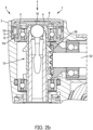
Fig. 2b - is a schematic partial cross-sectional enlarged view of the head of the dental handpiece inFig 1 , taken along the line I-I in the actuated state; -
Fig. 2c - is a schematic partial cross-sectional view of the head of the dental handpiece ofFig.1 , taken along the line II-II; -
Fig. 2d - is a schematic partial cross-sectional enlarged view of the head of a dental handpiece according to an alternative embodiment of the invention, taken along the line II-II inFig 1 ; -
Fig. 3 - is a schematic partial cross-sectional enlarged view of the clamping mechanism inside the bearings of the dental handpiece inFig 1 , taken along the line I-I; -
Fig. 4a - is a schematic partial cross-sectional enlarged view of the clamping mechanism of -
Fig. 3 without the bearings; -
Fig. 4b - is a schematic partial cross-sectional view of the clamping mechanism ofFig 4a , in the actuated state; -
Fig. 5a - is a schematic side view of the chuck of the dental handpiece inFig 1 ; -
Fig. 5b - is a schematic perspective view of the chuck of the dental handpiece inFig 1 ; -
Fig. 6a - is a schematic perspective view of the flange collar (hat-shaped) of the dental handpiece inFig 1 ; -
Fig. 6b - is a schematic perspective view of the outer race and the inner race of the dental handpiece inFig 1 ; -
Fig. 6c - is a schematic perspective view of the cap of the dental handpiece inFig 1 ; -
Fig. 6d - is a schematic perspective view of the screw ring of the dental handpiece inFig 1 ; -
Fig. 7a - is a schematic vertical cross sectional view of the two-piece push button of the dental handpiece inFig 2c ; -
Fig. 7b - is a schematic perspective view of the two-piece push button inFig 7a ; -
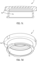
Fig. 7c - is a schematic vertical cross sectional view of the single-piece push button of the dental handpiece inFig 2d ; -
Fig. 7d - is a schematic perspective view of the single-piece push button inFig 7c ; - The reference numbers shown in the drawings denote the elements as listed below and will be referred to in the subsequent description of the exemplary embodiments.
- 1.
- Dental handpiece
- 2.
- Dental drill (burr)
- 3.
- Body
- 4.
Head 5. - Housing
5a. Gap
5b. Radial inner surface - 6.
- Internal Thread
- 7.
- Pushbutton
7a. Radial inner surface
7b. Radial outer surface - 8.
- Cap
- 9.
- Flange collar (hat-shaped)
9a. Claw
9b. Air Gap (thermal insulation) - 9'
- Cap
- 10.
- Contact surface (point like)
- 11.
- Spring (cone shaped)
- 12.
- Guide
- 13.
- Clamping means
- 14.
- Ball
- 15.
- Hollow shaft
- 16.
- Gear
- 17.
- Opening
- 18.
- Stop Edge
- 19.
- 19' Bearing
- 20.
- Outer race
20a. Radial outer surface - 21.
- Inner race
- 22.
- Balls
- 23.
- Retainer
- 24.
- Screw ring
- 25.
- Nose
- 26.
- Chuck
- 27.
- Arm
27a. Contact point - 28.
- Cut-out
- 29.
- Large diameter portion
- 30.
- Small diameter portion
- 31.
- Contact edge (Burr stop)
- 32.
- Driving shaft
- 33.
- Bearing
- 34.
- Outer race
- 35.
- Inner race
- 36.
- Balls
- 37.
- Retainer
- 38.
- Crown gear
- A:
- Axial Direction
- R:
- Radial Direction
- S:
- Radial Clearance
- F:
- Actuation Force
-
Fig. 1 shows a dental handpiece (1) according to an embodiment of the invention. As shown inFig. 1 , dental handpiece (1) has a body (3) and a head (4). A dental drill (2) is detachably attached to the head (4).Fig. 2a shows an enlarged cross-sectional view of the head (4). As shown inFig. 2a , the head (4) has a housing (5) which accommodates a clamping means (13). As shown inFig. 4a the clamping means (13) has a chuck (26) with resilient arms (27) for releasably clamping the dental drill (2). A hollow shaft (15) is rotatably arranged inside the head (4). The chuck (26) is fixed into the hollow shaft (15) to rotate with same. The dental handpiece (1) has a driving means such as a motor (not shown) for rotating the hollow shaft (15). The driving means is coupled to a driving shaft (32) as shown inFig. 2a , that is rotatably held through a bearing (33) having an outer race (34), an inner race (35), multiple balls (36), and a retainer (37). The end of the driving shaft (32) has a crown gear (38) that meshes with a gear (16) on the hollow shaft (15). As shown inFig. 3 the hollow shaft (15) is rotatably held through a couple of bearings (19; 19') mounted into the housing (5). Each bearing (19;19') has an outer race (20) and inner race (21), multiple balls (22) and a retainer (23). - As shown in
Fig. 3 , the clamping means (13) has a ball (14), preferably made of ceramic material, which is axially movably arranged inside the rotatable hollow shaft (15) and in direct contact with the resilient arms (27) of the chuck (26). The ball (14) partly protrudes through an opening (17) in the upper end of the hollow shaft (15). The size of the opening (17) is smaller than the size of the ball (14) so that it is retained partly within the hollow shaft (15). As shown inFig. 3 the opening (17) has an annular stop edge (18) which restricts the outwards movement of that ball (14). As shown inFig. 2a andFig. 2b the dental handpiece (1) has a push button (7) which is arranged in the head (4) and configured to contact, when pressed by a user, the partly protruding ball (14) and move the ball (14) downwardly in between the resilient arms (27) to flex the resilient arms (27) radially outwards and release the dental drill (2). As shown inFig. 5a the chuck (26) has two diametrically opposed cut-outs (28) in its upper portion to form the two resilient arms (27). As shown inFig. 5b , a linear semi cylindrical channel is formed into the upper portion of the chuck (26) whose edges form two diametrically opposed contact points (27a) to contact the ball (14). As shown inFig. 3 , the chuck (26) has a large diameter portion (29) and a small diameter portion (30). When the resilient arms (27) are retracted the dental drill (2) can be manually inserted only until the upper end of the large diameter portion (29). When the resilient arms (27) are flexed through the ball (14), the dental drill (2) can be further inserted into the small diameter portion (30) until it abuts against the contact edge (31) (Burr stop). Once the push button (7) is released, the resilient arms (27) are retracted, and the dental drill (2) is clamped in the small diameter portion (30) between the resilient arms (27). The resilient arms (27) also bias the ball (14) inside the rotatable hollow shaft (15) towards the opening (17). As shown inFig. 2a , the pushbutton (7) has a cap (8), and a hat-shaped flange collar (9) arranged inside the cap (8) and fixed thereto. The hat-shaped flange collar (9) has a point like contact surface (10), preferably planar, for the ball (14). The pushbutton (7) has a biasing means such a spring (11), preferably a cone shaped spring (11) to move the push button (7) away and detach it from the ball (14). As shown inFig. 2a , the point like contact surface (10) is not in contact with the ball (14) when the push button (7) is released. As shown inFig. 2b , the contact surface (10) comes in point contact with the upper side of the ball (14) when the push button (7) is pressed downwards. -
Fig. 2c shows an enlarged view of the two-piece pushbutton (7) inFig. 2a which is configured by the cap (8) and the hat-shaped Flange collar (9).Fig. 7a and Fig. 7b , show the two-piece push button (7) in more detail. -
Fig. 2d shows an alternative embodiment, wherein the cap (9') is provided as a single piece instead of two separate pieces. All other features remain the same. Thereby the number of pieces can be further reduced.Fig. 7c and 7d , show the single-piece push button (7) in more detail. - According to the alternative embodiments as shown in
Fig. 2c and2d , a radial inner surface (7a) of the push button (7) is arranged to contact and slide on a radial outer surface (20a) of the outer race (20) which configures a guide (12) for the moving push button (7). The radial direction is perpendicular to the axial direction (A) of the dental drill (2). A radial clearance (s) is arranged between a radial inner surface (5b) of the housing (5) and a radial outer surface (7b) of the push button (7). - As shown in
Fig. 2a , the housing (5) has an internal thread (6) which receives a screw ring (24). The mounting flange of the upper bearing (19) is fixed to its mounting position through the screw ring (24). The screw ring (24) has a nose (25) which can be seen inFig. 2d but not inFig.2a . The cross-sectional views respectively inFig. 2a andFig. 2d are rotated about 90 degrees with respect to each other. The cross-section inFig. 2a is along the line I-I as shown inFig. 1 and the cross section inFig. 2d is along the line II-II as shown inFig. 1 . As shown inFig. 2d , the nose (25) extends radially inwards and can abut from below against the claw (9a) of the hat-shaped flange collar (9) which extends radially outwards and prevents the push button (7) from disengaging from the housing (5). The hat-shaped flange collar (9) can be provided separately from or integrally with the cap (8;9'). In the former case an air gap (9b) is preferably formed underneath the cap (8) to improve thermal insulation as shown inFig. 2a . Alternatively the air gap (9b) may be filled with a material that is a poor heat-conductor. - As shown in
Fig. 2a andFig.2d , the inner surface of the hat-shaped flange collar (9) slides on the outer surface of outer race (20) while being in contact with the latter which configures a guide (12) for the push button (7) movement. The nose (25) of the screw ring (24) is arranged above the claw (9a) of the hat-shaped flange collar (9). The hat-shaped flange collar (9) does not contact the inner radial surface of the screw ring (24). The housing (5) has a gap (5a) directly above the screw ring (24) and the nose (25), which allows the cap (8;9') to move upwards or downwards during the clamping/releasing operation. The screw ring (24) is entirely embedded/recessed inside the housing (5) and does not project outside the head (4). Thereby, the height of the head (4) can be reduced. Thereby also the diameter of the cap (8,9') can be increased so that the actuating pressure on the finger is reduced. The outer cylindrical surface of the cap (8;9') does not contact the inner surface of the housing (5) during its entire movement thanks to the sufficient radial clearance (S). Thus, guide (12) serves as a guiding contact surface for the up/down movement of the cap (8;9'). Through the above described configuration, the height and diameter of the head (4) can be further reduced.
Claims (1)
- A dental handpiece (1) comprising:a head (4);a clamping means (13) which is rotatably arranged within a bearing (19) inside the head (4), and adapted for releasably clamping a dental drill (2), wherein the bearing (19) has an inner race (21) fixed to the clamping means (13) and an outer race (21) fixed to a housing (5) of the head (4);a driving means for rotating the clamping means (13) about an axial direction of the dental drill (2);a push button (7) which is arranged movably in the head (4) along the axial direction and configured to actuate the clamping means (13) to release the dental drill (2); anda biasing means to move the push button (7) away from the clamping means (13); characterized in thata radial inner surface (7a) of the push button (7) is arranged to contact and slide on a radial outer surface (20a) of the outer race (20) which configures a guide (12) for the moving push button (7), wherein the radial direction is perpendicular to the axial direction of the dental drill (2); and wherein a radial clearance (S) is arranged between a radial inner surface (5b) of the housing (5) and a radial outer surface (7b) of the push button (7).
Priority Applications (7)
| Application Number | Priority Date | Filing Date | Title |
|---|---|---|---|
| JP2024563580A JP2025523742A (en) | 2022-07-27 | 2023-06-28 | Dental handpiece having improved push button guidance - Patents.com |
| PCT/EP2023/067716 WO2024022718A1 (en) | 2022-07-27 | 2023-06-28 | Dental handpiece having an improved push button guidance |
| US18/870,304 US20250331950A1 (en) | 2022-07-27 | 2023-06-28 | Dental handpiece having an improved push button guidance |
| JP2024564725A JP2025523743A (en) | 2022-07-27 | 2023-06-28 | Dental handpiece having chuck with integral plunger ball - Patents.com |
| US18/998,034 US20260020934A1 (en) | 2022-07-27 | 2023-06-28 | Dental handpiece having a chuck with an integrated plunger ball |
| EP23734684.6A EP4561490A1 (en) | 2022-07-27 | 2023-06-28 | Dental handpiece having a chuck with an integrated plunger ball |
| PCT/EP2023/067723 WO2024022719A1 (en) | 2022-07-27 | 2023-06-28 | Dental handpiece having a chuck with an integrated plunger ball |
Applications Claiming Priority (1)
| Application Number | Priority Date | Filing Date | Title |
|---|---|---|---|
| EP22187241.9A EP4311516B1 (en) | 2022-07-27 | 2022-07-27 | Dental handpiece having a chuck with an integrated plunger ball |
Publications (2)
| Publication Number | Publication Date |
|---|---|
| EP4311517A1 true EP4311517A1 (en) | 2024-01-31 |
| EP4311517B1 EP4311517B1 (en) | 2025-10-29 |
Family
ID=82748452
Family Applications (2)
| Application Number | Title | Priority Date | Filing Date |
|---|---|---|---|
| EP22187241.9A Active EP4311516B1 (en) | 2022-07-27 | 2022-07-27 | Dental handpiece having a chuck with an integrated plunger ball |
| EP22195526.3A Active EP4311517B1 (en) | 2022-07-27 | 2022-09-14 | Dental handpiece having an improved push button guidance |
Family Applications Before (1)
| Application Number | Title | Priority Date | Filing Date |
|---|---|---|---|
| EP22187241.9A Active EP4311516B1 (en) | 2022-07-27 | 2022-07-27 | Dental handpiece having a chuck with an integrated plunger ball |
Country Status (1)
| Country | Link |
|---|---|
| EP (2) | EP4311516B1 (en) |
Citations (4)
| Publication number | Priority date | Publication date | Assignee | Title |
|---|---|---|---|---|
| EP0639354A2 (en) | 1993-08-20 | 1995-02-22 | Nakanishi Inc. | Dental handpiece having rotatable contact member |
| EP1733696A1 (en) | 2005-06-15 | 2006-12-20 | Bien-Air Holding SA | Handpiece for dental or surgical use with an elastic collet |
| EP2959860A1 (en) | 2014-06-27 | 2015-12-30 | Bien-Air Holding SA | Handpiece for dental or surgical applications |
| EP3412244A1 (en) * | 2017-06-07 | 2018-12-12 | Sirona Dental Systems GmbH | Dental hand or angle piece with a rotating tool |
Family Cites Families (2)
| Publication number | Priority date | Publication date | Assignee | Title |
|---|---|---|---|---|
| CH667197A5 (en) * | 1986-05-13 | 1988-09-30 | David Mosimann | DEVICE FOR CONTROLLING MEANS FOR FIXING A TOOL IN A ROTOR. |
| JPH02130619U (en) * | 1989-03-31 | 1990-10-29 |
-
2022
- 2022-07-27 EP EP22187241.9A patent/EP4311516B1/en active Active
- 2022-09-14 EP EP22195526.3A patent/EP4311517B1/en active Active
Patent Citations (4)
| Publication number | Priority date | Publication date | Assignee | Title |
|---|---|---|---|---|
| EP0639354A2 (en) | 1993-08-20 | 1995-02-22 | Nakanishi Inc. | Dental handpiece having rotatable contact member |
| EP1733696A1 (en) | 2005-06-15 | 2006-12-20 | Bien-Air Holding SA | Handpiece for dental or surgical use with an elastic collet |
| EP2959860A1 (en) | 2014-06-27 | 2015-12-30 | Bien-Air Holding SA | Handpiece for dental or surgical applications |
| EP3412244A1 (en) * | 2017-06-07 | 2018-12-12 | Sirona Dental Systems GmbH | Dental hand or angle piece with a rotating tool |
Also Published As
| Publication number | Publication date |
|---|---|
| EP4311517B1 (en) | 2025-10-29 |
| EP4311516A1 (en) | 2024-01-31 |
| EP4311516B1 (en) | 2025-09-10 |
Similar Documents
| Publication | Publication Date | Title |
|---|---|---|
| US4536157A (en) | Lever actuated chuck mechanism for dental handpiece | |
| US4199160A (en) | Surgical drill chuck | |
| JP7532359B2 (en) | Dental handpiece and push button for dental handpiece | |
| JP4969921B2 (en) | Dental or medical handpiece with flexible clamp | |
| CN115971574A (en) | Processing tool | |
| US10004571B2 (en) | Chuck mechanism for dental handpiece and dental handpiece using the mechanism | |
| EP4311517B1 (en) | Dental handpiece having an improved push button guidance | |
| US20250331950A1 (en) | Dental handpiece having an improved push button guidance | |
| US4575338A (en) | Ball type bur gripping mechanism for dental handpiece | |
| US20240075541A1 (en) | Deburring tool | |
| JPS62281938A (en) | Apparatus for operating tool clamping means | |
| US20020177101A1 (en) | Dental handpiece with tool holder | |
| JP2549926Y2 (en) | Clamping device | |
| JP7065055B2 (en) | Deburring tool and deburring method | |
| KR101515529B1 (en) | Medical device for general surgery | |
| JPH11342138A (en) | Removable fixing device for medical or dental rotating tools | |
| US5653453A (en) | Collet chuck | |
| US20140199654A1 (en) | Medical or dental handpiece | |
| US20230190407A1 (en) | Dental handpiece | |
| KR200428275Y1 (en) | Handheld Pushing Device | |
| JP2951935B1 (en) | Dental handpiece chuck mechanism | |
| JPH07255747A (en) | Dental handpiece | |
| AU2024264728A1 (en) | Handpiece with rotary knob to operate the tool holder |
Legal Events
| Date | Code | Title | Description |
|---|---|---|---|
| PUAI | Public reference made under article 153(3) epc to a published international application that has entered the european phase |
Free format text: ORIGINAL CODE: 0009012 |
|
| STAA | Information on the status of an ep patent application or granted ep patent |
Free format text: STATUS: THE APPLICATION HAS BEEN PUBLISHED |
|
| AK | Designated contracting states |
Kind code of ref document: A1 Designated state(s): AL AT BE BG CH CY CZ DE DK EE ES FI FR GB GR HR HU IE IS IT LI LT LU LV MC MK MT NL NO PL PT RO RS SE SI SK SM TR |
|
| STAA | Information on the status of an ep patent application or granted ep patent |
Free format text: STATUS: REQUEST FOR EXAMINATION WAS MADE |
|
| 17P | Request for examination filed |
Effective date: 20240722 |
|
| RBV | Designated contracting states (corrected) |
Designated state(s): AL AT BE BG CH CY CZ DE DK EE ES FI FR GB GR HR HU IE IS IT LI LT LU LV MC MK MT NL NO PL PT RO RS SE SI SK SM TR |
|
| GRAP | Despatch of communication of intention to grant a patent |
Free format text: ORIGINAL CODE: EPIDOSNIGR1 |
|
| STAA | Information on the status of an ep patent application or granted ep patent |
Free format text: STATUS: GRANT OF PATENT IS INTENDED |
|
| INTG | Intention to grant announced |
Effective date: 20250403 |
|
| GRAS | Grant fee paid |
Free format text: ORIGINAL CODE: EPIDOSNIGR3 |
|
| GRAA | (expected) grant |
Free format text: ORIGINAL CODE: 0009210 |
|
| STAA | Information on the status of an ep patent application or granted ep patent |
Free format text: STATUS: THE PATENT HAS BEEN GRANTED |
|
| AK | Designated contracting states |
Kind code of ref document: B1 Designated state(s): AL AT BE BG CH CY CZ DE DK EE ES FI FR GB GR HR HU IE IS IT LI LT LU LV MC MK MT NL NO PL PT RO RS SE SI SK SM TR |
|
| REG | Reference to a national code |
Ref country code: CH Ref legal event code: F10 Free format text: ST27 STATUS EVENT CODE: U-0-0-F10-F00 (AS PROVIDED BY THE NATIONAL OFFICE) Effective date: 20251029 Ref country code: GB Ref legal event code: FG4D |
|
| REG | Reference to a national code |
Ref country code: IE Ref legal event code: FG4D |
|
| REG | Reference to a national code |
Ref country code: DE Ref legal event code: R096 Ref document number: 602022023832 Country of ref document: DE |
|
| P01 | Opt-out of the competence of the unified patent court (upc) registered |
Free format text: CASE NUMBER: UPC_APP_0013099_4311517/2025 Effective date: 20251112 |
|
| REG | Reference to a national code |
Ref country code: NL Ref legal event code: MP Effective date: 20251029 |
|
| PG25 | Lapsed in a contracting state [announced via postgrant information from national office to epo] |
Ref country code: ES Free format text: LAPSE BECAUSE OF FAILURE TO SUBMIT A TRANSLATION OF THE DESCRIPTION OR TO PAY THE FEE WITHIN THE PRESCRIBED TIME-LIMIT Effective date: 20251029 |
|
| REG | Reference to a national code |
Ref country code: LT Ref legal event code: MG9D |
|
| PG25 | Lapsed in a contracting state [announced via postgrant information from national office to epo] |
Ref country code: NO Free format text: LAPSE BECAUSE OF FAILURE TO SUBMIT A TRANSLATION OF THE DESCRIPTION OR TO PAY THE FEE WITHIN THE PRESCRIBED TIME-LIMIT Effective date: 20260129 |
|
| PG25 | Lapsed in a contracting state [announced via postgrant information from national office to epo] |
Ref country code: AT Free format text: LAPSE BECAUSE OF FAILURE TO SUBMIT A TRANSLATION OF THE DESCRIPTION OR TO PAY THE FEE WITHIN THE PRESCRIBED TIME-LIMIT Effective date: 20251029 Ref country code: FI Free format text: LAPSE BECAUSE OF FAILURE TO SUBMIT A TRANSLATION OF THE DESCRIPTION OR TO PAY THE FEE WITHIN THE PRESCRIBED TIME-LIMIT Effective date: 20251029 Ref country code: HR Free format text: LAPSE BECAUSE OF FAILURE TO SUBMIT A TRANSLATION OF THE DESCRIPTION OR TO PAY THE FEE WITHIN THE PRESCRIBED TIME-LIMIT Effective date: 20251029 |
|
| REG | Reference to a national code |
Ref country code: AT Ref legal event code: MK05 Ref document number: 1850751 Country of ref document: AT Kind code of ref document: T Effective date: 20251029 |
|
| PG25 | Lapsed in a contracting state [announced via postgrant information from national office to epo] |
Ref country code: NL Free format text: LAPSE BECAUSE OF FAILURE TO SUBMIT A TRANSLATION OF THE DESCRIPTION OR TO PAY THE FEE WITHIN THE PRESCRIBED TIME-LIMIT Effective date: 20251029 |
|
| PG25 | Lapsed in a contracting state [announced via postgrant information from national office to epo] |
Ref country code: RS Free format text: LAPSE BECAUSE OF FAILURE TO SUBMIT A TRANSLATION OF THE DESCRIPTION OR TO PAY THE FEE WITHIN THE PRESCRIBED TIME-LIMIT Effective date: 20260129 |
|
| PG25 | Lapsed in a contracting state [announced via postgrant information from national office to epo] |
Ref country code: IS Free format text: LAPSE BECAUSE OF FAILURE TO SUBMIT A TRANSLATION OF THE DESCRIPTION OR TO PAY THE FEE WITHIN THE PRESCRIBED TIME-LIMIT Effective date: 20260228 |
|
| PG25 | Lapsed in a contracting state [announced via postgrant information from national office to epo] |
Ref country code: PT Free format text: LAPSE BECAUSE OF FAILURE TO SUBMIT A TRANSLATION OF THE DESCRIPTION OR TO PAY THE FEE WITHIN THE PRESCRIBED TIME-LIMIT Effective date: 20260302 |
|
| PG25 | Lapsed in a contracting state [announced via postgrant information from national office to epo] |
Ref country code: PL Free format text: LAPSE BECAUSE OF FAILURE TO SUBMIT A TRANSLATION OF THE DESCRIPTION OR TO PAY THE FEE WITHIN THE PRESCRIBED TIME-LIMIT Effective date: 20251029 |
|
| PG25 | Lapsed in a contracting state [announced via postgrant information from national office to epo] |
Ref country code: LV Free format text: LAPSE BECAUSE OF FAILURE TO SUBMIT A TRANSLATION OF THE DESCRIPTION OR TO PAY THE FEE WITHIN THE PRESCRIBED TIME-LIMIT Effective date: 20251029 |
|
| PG25 | Lapsed in a contracting state [announced via postgrant information from national office to epo] |
Ref country code: BG Free format text: LAPSE BECAUSE OF FAILURE TO SUBMIT A TRANSLATION OF THE DESCRIPTION OR TO PAY THE FEE WITHIN THE PRESCRIBED TIME-LIMIT Effective date: 20251029 |
|
| PG25 | Lapsed in a contracting state [announced via postgrant information from national office to epo] |
Ref country code: LT Free format text: LAPSE BECAUSE OF FAILURE TO SUBMIT A TRANSLATION OF THE DESCRIPTION OR TO PAY THE FEE WITHIN THE PRESCRIBED TIME-LIMIT Effective date: 20251029 |
|
| PG25 | Lapsed in a contracting state [announced via postgrant information from national office to epo] |
Ref country code: SM Free format text: LAPSE BECAUSE OF FAILURE TO SUBMIT A TRANSLATION OF THE DESCRIPTION OR TO PAY THE FEE WITHIN THE PRESCRIBED TIME-LIMIT Effective date: 20251029 |
|
| PG25 | Lapsed in a contracting state [announced via postgrant information from national office to epo] |
Ref country code: DK Free format text: LAPSE BECAUSE OF FAILURE TO SUBMIT A TRANSLATION OF THE DESCRIPTION OR TO PAY THE FEE WITHIN THE PRESCRIBED TIME-LIMIT Effective date: 20251029 |
|
| PG25 | Lapsed in a contracting state [announced via postgrant information from national office to epo] |
Ref country code: IT Free format text: LAPSE BECAUSE OF FAILURE TO SUBMIT A TRANSLATION OF THE DESCRIPTION OR TO PAY THE FEE WITHIN THE PRESCRIBED TIME-LIMIT Effective date: 20251029 |
|
| PG25 | Lapsed in a contracting state [announced via postgrant information from national office to epo] |
Ref country code: EE Free format text: LAPSE BECAUSE OF FAILURE TO SUBMIT A TRANSLATION OF THE DESCRIPTION OR TO PAY THE FEE WITHIN THE PRESCRIBED TIME-LIMIT Effective date: 20251029 |
|
| PG25 | Lapsed in a contracting state [announced via postgrant information from national office to epo] |
Ref country code: CZ Free format text: LAPSE BECAUSE OF FAILURE TO SUBMIT A TRANSLATION OF THE DESCRIPTION OR TO PAY THE FEE WITHIN THE PRESCRIBED TIME-LIMIT Effective date: 20251029 |
|
| PG25 | Lapsed in a contracting state [announced via postgrant information from national office to epo] |
Ref country code: SK Free format text: LAPSE BECAUSE OF FAILURE TO SUBMIT A TRANSLATION OF THE DESCRIPTION OR TO PAY THE FEE WITHIN THE PRESCRIBED TIME-LIMIT Effective date: 20251029 |
|
| PG25 | Lapsed in a contracting state [announced via postgrant information from national office to epo] |
Ref country code: SE Free format text: LAPSE BECAUSE OF FAILURE TO SUBMIT A TRANSLATION OF THE DESCRIPTION OR TO PAY THE FEE WITHIN THE PRESCRIBED TIME-LIMIT Effective date: 20251029 |