EP4311487A1 - Radar-based activity classification - Google Patents
Radar-based activity classification Download PDFInfo
- Publication number
- EP4311487A1 EP4311487A1 EP23188168.1A EP23188168A EP4311487A1 EP 4311487 A1 EP4311487 A1 EP 4311487A1 EP 23188168 A EP23188168 A EP 23188168A EP 4311487 A1 EP4311487 A1 EP 4311487A1
- Authority
- EP
- European Patent Office
- Prior art keywords
- radar
- point cloud
- generating
- neural network
- graph
- Prior art date
- Legal status (The legal status is an assumption and is not a legal conclusion. Google has not performed a legal analysis and makes no representation as to the accuracy of the status listed.)
- Granted
Links
Images


Classifications
-
- G—PHYSICS
- G06—COMPUTING OR CALCULATING; COUNTING
- G06V—IMAGE OR VIDEO RECOGNITION OR UNDERSTANDING
- G06V10/00—Arrangements for image or video recognition or understanding
- G06V10/70—Arrangements for image or video recognition or understanding using pattern recognition or machine learning
- G06V10/764—Arrangements for image or video recognition or understanding using pattern recognition or machine learning using classification, e.g. of video objects
-
- G—PHYSICS
- G01—MEASURING; TESTING
- G01S—RADIO DIRECTION-FINDING; RADIO NAVIGATION; DETERMINING DISTANCE OR VELOCITY BY USE OF RADIO WAVES; LOCATING OR PRESENCE-DETECTING BY USE OF THE REFLECTION OR RERADIATION OF RADIO WAVES; ANALOGOUS ARRANGEMENTS USING OTHER WAVES
- G01S7/00—Details of systems according to groups G01S13/00, G01S15/00, G01S17/00
- G01S7/02—Details of systems according to groups G01S13/00, G01S15/00, G01S17/00 of systems according to group G01S13/00
- G01S7/41—Details of systems according to groups G01S13/00, G01S15/00, G01S17/00 of systems according to group G01S13/00 using analysis of echo signal for target characterisation; Target signature; Target cross-section
- G01S7/414—Discriminating targets with respect to background clutter
-
- G—PHYSICS
- G06—COMPUTING OR CALCULATING; COUNTING
- G06N—COMPUTING ARRANGEMENTS BASED ON SPECIFIC COMPUTATIONAL MODELS
- G06N3/00—Computing arrangements based on biological models
- G06N3/02—Neural networks
- G06N3/04—Architecture, e.g. interconnection topology
- G06N3/0464—Convolutional networks [CNN, ConvNet]
-
- A—HUMAN NECESSITIES
- A61—MEDICAL OR VETERINARY SCIENCE; HYGIENE
- A61B—DIAGNOSIS; SURGERY; IDENTIFICATION
- A61B5/00—Measuring for diagnostic purposes; Identification of persons
- A61B5/05—Detecting, measuring or recording for diagnosis by means of electric currents or magnetic fields; Measuring using microwaves or radio waves
- A61B5/0507—Detecting, measuring or recording for diagnosis by means of electric currents or magnetic fields; Measuring using microwaves or radio waves using microwaves or terahertz waves
-
- A—HUMAN NECESSITIES
- A61—MEDICAL OR VETERINARY SCIENCE; HYGIENE
- A61B—DIAGNOSIS; SURGERY; IDENTIFICATION
- A61B5/00—Measuring for diagnostic purposes; Identification of persons
- A61B5/103—Measuring devices for testing the shape, pattern, colour, size or movement of the body or parts thereof, for diagnostic purposes
- A61B5/11—Measuring movement of the entire body or parts thereof, e.g. head or hand tremor or mobility of a limb
- A61B5/1116—Determining posture transitions
- A61B5/1117—Fall detection
-
- A—HUMAN NECESSITIES
- A61—MEDICAL OR VETERINARY SCIENCE; HYGIENE
- A61B—DIAGNOSIS; SURGERY; IDENTIFICATION
- A61B5/00—Measuring for diagnostic purposes; Identification of persons
- A61B5/103—Measuring devices for testing the shape, pattern, colour, size or movement of the body or parts thereof, for diagnostic purposes
- A61B5/11—Measuring movement of the entire body or parts thereof, e.g. head or hand tremor or mobility of a limb
- A61B5/1118—Determining activity level
-
- A—HUMAN NECESSITIES
- A61—MEDICAL OR VETERINARY SCIENCE; HYGIENE
- A61B—DIAGNOSIS; SURGERY; IDENTIFICATION
- A61B5/00—Measuring for diagnostic purposes; Identification of persons
- A61B5/72—Signal processing specially adapted for physiological signals or for diagnostic purposes
- A61B5/7235—Details of waveform analysis
- A61B5/7264—Classification of physiological signals or data, e.g. using neural networks, statistical classifiers, expert systems or fuzzy systems
- A61B5/7267—Classification of physiological signals or data, e.g. using neural networks, statistical classifiers, expert systems or fuzzy systems involving training the classification device
-
- G—PHYSICS
- G01—MEASURING; TESTING
- G01S—RADIO DIRECTION-FINDING; RADIO NAVIGATION; DETERMINING DISTANCE OR VELOCITY BY USE OF RADIO WAVES; LOCATING OR PRESENCE-DETECTING BY USE OF THE REFLECTION OR RERADIATION OF RADIO WAVES; ANALOGOUS ARRANGEMENTS USING OTHER WAVES
- G01S13/00—Systems using the reflection or reradiation of radio waves, e.g. radar systems; Analogous systems using reflection or reradiation of waves whose nature or wavelength is irrelevant or unspecified
- G01S13/02—Systems using reflection of radio waves, e.g. primary radar systems; Analogous systems
- G01S13/50—Systems of measurement based on relative movement of target
- G01S13/58—Velocity or trajectory determination systems; Sense-of-movement determination systems
- G01S13/583—Velocity or trajectory determination systems; Sense-of-movement determination systems using transmission of continuous unmodulated waves, amplitude-, frequency-, or phase-modulated waves and based upon the Doppler effect resulting from movement of targets
- G01S13/584—Velocity or trajectory determination systems; Sense-of-movement determination systems using transmission of continuous unmodulated waves, amplitude-, frequency-, or phase-modulated waves and based upon the Doppler effect resulting from movement of targets adapted for simultaneous range and velocity measurements
-
- G—PHYSICS
- G01—MEASURING; TESTING
- G01S—RADIO DIRECTION-FINDING; RADIO NAVIGATION; DETERMINING DISTANCE OR VELOCITY BY USE OF RADIO WAVES; LOCATING OR PRESENCE-DETECTING BY USE OF THE REFLECTION OR RERADIATION OF RADIO WAVES; ANALOGOUS ARRANGEMENTS USING OTHER WAVES
- G01S13/00—Systems using the reflection or reradiation of radio waves, e.g. radar systems; Analogous systems using reflection or reradiation of waves whose nature or wavelength is irrelevant or unspecified
- G01S13/86—Combinations of radar systems with non-radar systems, e.g. sonar, direction finder
- G01S13/867—Combination of radar systems with cameras
-
- G—PHYSICS
- G01—MEASURING; TESTING
- G01S—RADIO DIRECTION-FINDING; RADIO NAVIGATION; DETERMINING DISTANCE OR VELOCITY BY USE OF RADIO WAVES; LOCATING OR PRESENCE-DETECTING BY USE OF THE REFLECTION OR RERADIATION OF RADIO WAVES; ANALOGOUS ARRANGEMENTS USING OTHER WAVES
- G01S13/00—Systems using the reflection or reradiation of radio waves, e.g. radar systems; Analogous systems using reflection or reradiation of waves whose nature or wavelength is irrelevant or unspecified
- G01S13/88—Radar or analogous systems specially adapted for specific applications
- G01S13/89—Radar or analogous systems specially adapted for specific applications for mapping or imaging
-
- G—PHYSICS
- G01—MEASURING; TESTING
- G01S—RADIO DIRECTION-FINDING; RADIO NAVIGATION; DETERMINING DISTANCE OR VELOCITY BY USE OF RADIO WAVES; LOCATING OR PRESENCE-DETECTING BY USE OF THE REFLECTION OR RERADIATION OF RADIO WAVES; ANALOGOUS ARRANGEMENTS USING OTHER WAVES
- G01S7/00—Details of systems according to groups G01S13/00, G01S15/00, G01S17/00
- G01S7/02—Details of systems according to groups G01S13/00, G01S15/00, G01S17/00 of systems according to group G01S13/00
- G01S7/41—Details of systems according to groups G01S13/00, G01S15/00, G01S17/00 of systems according to group G01S13/00 using analysis of echo signal for target characterisation; Target signature; Target cross-section
- G01S7/415—Identification of targets based on measurements of movement associated with the target
-
- G—PHYSICS
- G01—MEASURING; TESTING
- G01S—RADIO DIRECTION-FINDING; RADIO NAVIGATION; DETERMINING DISTANCE OR VELOCITY BY USE OF RADIO WAVES; LOCATING OR PRESENCE-DETECTING BY USE OF THE REFLECTION OR RERADIATION OF RADIO WAVES; ANALOGOUS ARRANGEMENTS USING OTHER WAVES
- G01S7/00—Details of systems according to groups G01S13/00, G01S15/00, G01S17/00
- G01S7/02—Details of systems according to groups G01S13/00, G01S15/00, G01S17/00 of systems according to group G01S13/00
- G01S7/41—Details of systems according to groups G01S13/00, G01S15/00, G01S17/00 of systems according to group G01S13/00 using analysis of echo signal for target characterisation; Target signature; Target cross-section
- G01S7/417—Details of systems according to groups G01S13/00, G01S15/00, G01S17/00 of systems according to group G01S13/00 using analysis of echo signal for target characterisation; Target signature; Target cross-section involving the use of neural networks
-
- G—PHYSICS
- G06—COMPUTING OR CALCULATING; COUNTING
- G06N—COMPUTING ARRANGEMENTS BASED ON SPECIFIC COMPUTATIONAL MODELS
- G06N3/00—Computing arrangements based on biological models
- G06N3/02—Neural networks
- G06N3/04—Architecture, e.g. interconnection topology
- G06N3/044—Recurrent networks, e.g. Hopfield networks
- G06N3/0442—Recurrent networks, e.g. Hopfield networks characterised by memory or gating, e.g. long short-term memory [LSTM] or gated recurrent units [GRU]
-
- G—PHYSICS
- G06—COMPUTING OR CALCULATING; COUNTING
- G06N—COMPUTING ARRANGEMENTS BASED ON SPECIFIC COMPUTATIONAL MODELS
- G06N3/00—Computing arrangements based on biological models
- G06N3/02—Neural networks
- G06N3/04—Architecture, e.g. interconnection topology
- G06N3/045—Combinations of networks
- G06N3/0455—Auto-encoder networks; Encoder-decoder networks
-
- G—PHYSICS
- G06—COMPUTING OR CALCULATING; COUNTING
- G06N—COMPUTING ARRANGEMENTS BASED ON SPECIFIC COMPUTATIONAL MODELS
- G06N3/00—Computing arrangements based on biological models
- G06N3/02—Neural networks
- G06N3/08—Learning methods
- G06N3/09—Supervised learning
-
- G—PHYSICS
- G06—COMPUTING OR CALCULATING; COUNTING
- G06V—IMAGE OR VIDEO RECOGNITION OR UNDERSTANDING
- G06V10/00—Arrangements for image or video recognition or understanding
- G06V10/70—Arrangements for image or video recognition or understanding using pattern recognition or machine learning
- G06V10/77—Processing image or video features in feature spaces; using data integration or data reduction, e.g. principal component analysis [PCA] or independent component analysis [ICA] or self-organising maps [SOM]; Blind source separation
- G06V10/80—Fusion, i.e. combining data from various sources at the sensor level, preprocessing level, feature extraction level or classification level
- G06V10/809—Fusion, i.e. combining data from various sources at the sensor level, preprocessing level, feature extraction level or classification level of classification results, e.g. where the classifiers operate on the same input data
-
- G—PHYSICS
- G06—COMPUTING OR CALCULATING; COUNTING
- G06V—IMAGE OR VIDEO RECOGNITION OR UNDERSTANDING
- G06V10/00—Arrangements for image or video recognition or understanding
- G06V10/70—Arrangements for image or video recognition or understanding using pattern recognition or machine learning
- G06V10/82—Arrangements for image or video recognition or understanding using pattern recognition or machine learning using neural networks
-
- G—PHYSICS
- G06—COMPUTING OR CALCULATING; COUNTING
- G06V—IMAGE OR VIDEO RECOGNITION OR UNDERSTANDING
- G06V10/00—Arrangements for image or video recognition or understanding
- G06V10/70—Arrangements for image or video recognition or understanding using pattern recognition or machine learning
- G06V10/84—Arrangements for image or video recognition or understanding using pattern recognition or machine learning using probabilistic graphical models from image or video features, e.g. Markov models or Bayesian networks
-
- G—PHYSICS
- G06—COMPUTING OR CALCULATING; COUNTING
- G06V—IMAGE OR VIDEO RECOGNITION OR UNDERSTANDING
- G06V40/00—Recognition of biometric, human-related or animal-related patterns in image or video data
- G06V40/20—Movements or behaviour, e.g. gesture recognition
- G06V40/23—Recognition of whole body movements, e.g. for sport training
-
- G—PHYSICS
- G08—SIGNALLING
- G08B—SIGNALLING SYSTEMS, e.g. PERSONAL CALLING SYSTEMS; ORDER TELEGRAPHS; ALARM SYSTEMS
- G08B21/00—Alarms responsive to a single specified undesired or abnormal condition and not otherwise provided for
- G08B21/02—Alarms for ensuring the safety of persons
- G08B21/04—Alarms for ensuring the safety of persons responsive to non-activity, e.g. of elderly persons
- G08B21/0407—Alarms for ensuring the safety of persons responsive to non-activity, e.g. of elderly persons based on behaviour analysis
- G08B21/043—Alarms for ensuring the safety of persons responsive to non-activity, e.g. of elderly persons based on behaviour analysis detecting an emergency event, e.g. a fall
-
- G—PHYSICS
- G08—SIGNALLING
- G08B—SIGNALLING SYSTEMS, e.g. PERSONAL CALLING SYSTEMS; ORDER TELEGRAPHS; ALARM SYSTEMS
- G08B21/00—Alarms responsive to a single specified undesired or abnormal condition and not otherwise provided for
- G08B21/02—Alarms for ensuring the safety of persons
- G08B21/04—Alarms for ensuring the safety of persons responsive to non-activity, e.g. of elderly persons
- G08B21/0438—Sensor means for detecting
- G08B21/0492—Sensor dual technology, i.e. two or more technologies collaborate to extract unsafe condition, e.g. video tracking and RFID tracking
-
- G—PHYSICS
- G08—SIGNALLING
- G08B—SIGNALLING SYSTEMS, e.g. PERSONAL CALLING SYSTEMS; ORDER TELEGRAPHS; ALARM SYSTEMS
- G08B29/00—Checking or monitoring of signalling or alarm systems; Prevention or correction of operating errors, e.g. preventing unauthorised operation
- G08B29/18—Prevention or correction of operating errors
- G08B29/185—Signal analysis techniques for reducing or preventing false alarms or for enhancing the reliability of the system
- G08B29/186—Fuzzy logic; neural networks
Definitions
- the present disclosure relates generally to an electronic system and method, and, in particular embodiments, to radar-based activity classification.
- the elderly group e.g., 65+ years old
- Elderly falls account for a significant number of injuries, and many of the injuries are expensive to treat.
- elderly fall detection is an active research area.
- a system may be desirable for a system to automatically detect a fall of a (e.g., elderly) person (e.g., immediately) after the fall occurs, and trigger an alert so that the person is treated soon after the fall.
- a system may advantageously allow for continuous monitoring of a person, and may allow for prompt detection of a fall.
- People that may benefit from such a system includes people with dementia and other cognitive and/or physical impairments.
- Elderly fall detection may be performed in various ways. As a field of growing research, many proposals with different sensors have been developed. Popular systems for elderly fall detection include vision systems and wearable systems.
- Vision systems may be used to adequately detect elderly fall detection. However, Vision systems may be expensive, may exhibit low performance in occluded or partially occluded scenarios and low illumination scenarios, and may suffer from privacy concerns.
- Wearable systems may also be used for to adequately detect elderly fall detection.
- wearable systems may be uncomfortable to wear and may restrict the freedom of the person wearing it.
- a method as defined in claim 1 and a radar system as defined in claim 15 are provided.
- the dependent claims define further embodiments.
- a method includes: receiving raw data from a millimeter-wave radar sensor; generating a first radar-Doppler image based on the raw data; generating a first radar point cloud based on the first radar-Doppler image; using a graph encoder to generate a first graph representation vector indicative of one or more relationships between two or more parts of the target based on the first radar point cloud; generating a first cadence velocity diagram indicative of a periodicity of movement of one or more parts of the target based on the first radar-Doppler image; and classifying an activity of a target based on the first graph representation vector and the first cadence velocity diagram.
- a radar system includes: a radar sensor configured to transmit a plurality of radar signals towards a scene, receive a plurality of reflected radar signals from the scene, and generate raw data based on the plurality of reflected radar signals; and a processing system configured to: generate a first radar image based on the raw data, generate a first radar point cloud based on the first radar image, use a graph encoder to generate a first graph representation vector indicative of one or more relationships between two or more parts of the target based on the first radar point cloud, generate a first cadence velocity diagram indicative of a periodicity of movement of one or more parts of the target based on the first radar image, and classify an activity of a target located in the scene based on the first graph representation vector and the first cadence velocity diagram.
- a radar system includes: a millimeter-wave radar sensor configured to transmit a plurality of radar signals towards a scene, receive a plurality of reflected radar signals from the scene, and generate raw data based on the plurality of reflected radar signals; and a processing system configured to: generate a plurality of radar-Doppler images based on the raw data, generate a plurality of radar point clouds based on the plurality of radar-Doppler images, use a graph encoder to generate a plurality of graph representation vectors indicative of one or more relationships between two or more parts of the target based on the plurality of radar point clouds, generate a first cadence velocity diagram indicative of a periodicity of movement of one or more parts of the target based on the plurality of radar-Doppler images, and classify an activity of a target located in the scene based on the plurality of graph representation vectors and the first cadence velocity diagram.
- Embodiments of the present invention will be described in specific contexts, e.g., a radar-based activity classification system and method, e.g., for elderly fall detection.
- Embodiments of the present invention may be used for other types of activity classification, such as classifying various human activities (sitting, standing, walking, running, bending over, stretching, etc.), gesture recognition, etc.
- Radar-based systems for elderly fall detection have many advantages. Advantages of radar-based systems for elderly fall detection may include: lower cost than vision systems, little or no privacy concerns, less susceptible to a decrease in performance in occluded or partially occluded scenarios and low illumination scenarios, and allowing freedom of movement to the user.
- a radar-based system may distinguish between some activities and a fall. For example, a person sitting down or bent over to pick up something may be mistakenly detected as a fall, thereby causing false positives.
- a millimeter-wave radar system is advantageously able to distinguish between similar activities of a target (e.g., a person sitting down versus falling) and, thus, reduce the number of false positives, by encoding a radar point cloud using a graph encoder to obtain graph representation vectors indicative of relationships between different body parts during an activity of the target.
- a cadence-velocity diagram (CVD) is used to extract information about the periodicity of movement of different body parts during the activity of the target. Information from the CVD and the graph representation vectors is used to classify the activity of the target (e.g., a person falling or not falling).
- FIG. 1 shows a schematic diagram of millimeter-wave radar system 100, according to an embodiment of the present invention.
- Millimeter-wave radar system 100 includes millimeter-wave radar sensor 102 and processing system 104.
- millimeter-wave radar sensor 102 operates as a frequency-modulated continuous-wave (FMCW) radar sensor and transmits a plurality of TX radar signals 106, such as chirps, towards scene 120 using one or more transmitter (TX) antenna 114.
- the radar signals 106 are generated using RF and analog circuits 130.
- the radar signals 106 may be, e.g., in the 20 GHz to 122 GHz range. Other frequencies may also be used.
- the objects in scene 120 may include one or more static or moving objects, such as tables, walls, chairs, etc., idle and moving humans and animals, as well as periodically-moving objects, such as rotating fans. Other objects may also be present in scene 120.
- the radar signals 106 are reflected by objects in scene 120.
- the reflected radar signals 108 which are also referred to as the echo signal, are received by a plurality of receiving (RX) antennas 116.
- RF and analog circuits 130 processes the received reflected radar signals 108 using, e.g., band-pass filters (BPFs), low-pass filters (LPFs), mixers, low-noise amplifier (LNA), and/or intermediate frequency (IF) amplifiers in ways known in the art to generate an analog signal x out (t) per receiving antenna 116.
- BPFs band-pass filters
- LPFs low-pass filters
- LNA low-noise amplifier
- IF intermediate frequency
- the analog signals x out (t) are converted to raw digital data x out_dig ( n ) using analog-to-digital converter (ADC) 112.
- ADC analog-to-digital converter
- the raw digital data x out_dig ( n ) is processed by processing system 104 to detect one or more targets and their position, track such targets, and classify the activity of such targets.
- Controller 110 controls one or more circuits of millimeter-wave radar sensor 102, such as RF and analog circuit 130 and/or ADC 112. Controller 110 may be implemented, e.g., as a custom digital or mixed signal circuit, for example. Controller 110 may also be implemented in other ways, such as using a general-purpose processor or controller, for example. In some embodiments, processing system 104 implements a portion or all of controller 110.
- Processing system 104 may be implemented with a general-purpose processor, controller or digital signal processor (DSP) that includes, for example, combinatorial circuits coupled to a memory.
- processing system 104 may be implemented as an application specific integrated circuit (ASIC).
- ASIC application specific integrated circuit
- processing system 104 may be implemented with an ARM, RISC, or x86 architecture, for example.
- processing system 104 may include an artificial intelligence (AI) accelerator.
- AI artificial intelligence
- Some embodiments may use a combination of hardware accelerator and software running on a DSP or general-purpose microcontroller. Other implementations are also possible.
- millimeter-wave radar sensor 102 and a portion or all of processing system 104 may be implemented inside the same integrated circuit (IC).
- IC integrated circuit
- millimeter-wave radar sensor 102 and a portion or all of processing system 104 may be implemented in respective semiconductor substrates that are integrated in the same package.
- millimeter-wave radar sensor 102 and a portion or all of processing system 104 may be implemented in the same monolithic semiconductor substrate.
- millimeter-wave radar sensor 102 and processing system 104 are implemented in respective integrated circuits.
- a plurality of integrated circuits is used to implement millimeter-wave radar sensor 102.
- a plurality of integrated circuits is used to implement processing system 104.
- Other implementations are also possible.
- RF and analog circuits 130 may be implemented, e.g., as shown in Figure 1 .
- VCO voltage-controlled oscillator
- the VCO 136 is controlled by PLL 134, which receives a reference clock signal (e.g., 80 MHz) from reference oscillator 132.
- PLL 134 is controlled by a loop that includes frequency divider 138 and amplifier 140.
- Amplifier 137 may be used to drive transmitting antenna 114.
- the TX radar signals 106 transmitted by transmitting antenna 114 are reflected by objects in scene 120 and received by receiving antennas 116.
- the echo received by receiving antennas 116 are mixed with a replica of the signal transmitted by transmitting antenna 114 using respective mixers 146 to produce respective intermediate frequency (IF) signals x IF ( t ) (also known as beat signals).
- IF intermediate frequency
- the beat signals x IF ( t ) have a bandwidth between 10 kHz and 1 MHz. Beat signals with a bandwidth lower than 10 kHz or higher than 1 MHz is also possible.
- Respective amplifiers 145 may be used to receive the reflected radar signals from antennas 116.
- Beat signals x IF ( t ) may be respectively filtered with respective low-pass filters (LPFs) 148 and then sampled by ADC 112.
- ADC 112 is advantageously capable of sampling the filtered beat signals x out ( t ) with a sampling frequency that is much smaller than the frequency of the signal received by receiving antennas 116. Using FMCW radars, therefore, advantageously allows for a compact and low-cost implementation of ADC 112, in some embodiments.
- ADC 112 is a 12-bit ADC with multiple inputs. ADCs with higher resolution, such as 14-bits or higher, or with lower resolution, such as 10-bits, or lower, may also be used. In some embodiments, an ADC per receiver antenna may be used. Other implementations are also possible.
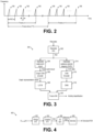
- FIG. 2 illustrates a sequence of chirps 106 transmitted by TX antenna 114, according to an embodiment of the present invention.
- chirps 106 are organized in a plurality of frames (also referred to as physical frames) and may be implemented as up-chirps.
- Some embodiments may use down-chirps or a combination of up-chirps and down-chirps, such as up-down chirps and down-up chirps.
- Other waveform shapes may also be used.
- each frame may include a plurality of chirps 106 (also referred to, generally, as pulses).
- the number of chirps in a frame is 64.
- Some embodiments may include more than 64 chirps per frame, such as 96 chirps, 128 chirps, 256 chirps, or more, or less than 64 chirps per frame, such as 32 chirps, 16 chirps, or less.
- frames are repeated every FT time.
- FT time is 50 ms.
- a different FT time may also be used, such as more than 50 ms, such as 60 ms, 100 ms, 200 ms, or more, or less than 50 ms, such as 45 ms, 40 ms, or less.
- the FT time is selected such that the time between the beginning of the last chirp of frame n and the beginning of the first chirp of frame n+1 is equal to PRT.
- Other embodiments may use or result in a different timing.
- the time between chirps of a frame is generally referred to as pulse repetition time (PRT).
- PRT pulse repetition time
- the PRT is 5 ms.
- a different PRT may also be used, such as less than 5 ms, such as 4 ms, 2 ms, 0.5 ms, or less, or more than 5 ms, such as 6 ms, or more.
- the duration of the chirp (from start to finish) is generally referred to as chirp time (CT).
- CT chirp time
- the chirp time may be, e.g., 64 ⁇ s. Higher chirp times, such as 128 ⁇ s, or higher, may also be used. Lower chirp times, may also be used.
- the chirp bandwidth may be, e.g., 4 GHz. Higher bandwidth, such as 6 GHz or higher, or lower bandwidth, such as 2 GHz, 1 GHz, or lower, may also be possible.
- the sampling frequency of millimeter-wave radar sensor 102 may be, e.g., 1 MHz. Higher sampling frequencies, such as 2 MHz or higher, or lower sampling frequencies, such as 500 kHz or lower, may also be possible.
- the number of samples used to generate each chirp may be, e.g., 64 samples.
- a higher number of samples, such as 128 samples, or higher, or a lower number of samples, such as 32 samples or lower, may also be used to generate each chirp.
- Figure 3 shows embodiment method 300 for activity classification of a target, according to an embodiment of the present invention.
- Method 300 may be implemented by processing system 104.
- Method 300 includes steps 302, 304, 306, 308, 314, 316, 318, and 320.
- the sequence of steps including steps 304, 306, and 308 may be performed in parallel with the sequence of steps including steps 314, 316, and 318.
- steps 302, 304, 306, 308, 314, 316, 318, and 320 may be performed continuously as new raw data is received (e.g., in a windowing operation).
- a range-Doppler image is generated based on raw data (e.g., X out_dig (n) ) received from, e.g., millimeter-wave radar sensor 102.
- the RDI may be generated in a conventional manner.
- a radar point cloud is generated.
- a radar point cloud may be understood as a scattered collection of points that represent one or more targets in a scene.
- the radar point cloud includes, for each point of the radar point cloud, three-dimensional (3D) coordinates (e.g., Cartesian or Polar), an intensity value, and Doppler value.
- 3D coordinates e.g., Cartesian or Polar
- a graph encoder such as a graph convolutional neural network (CNN) encoder, is used to generate a graph representation vector based on the radar point cloud (e.g., a graph representation of the radar point cloud) generated during step 304.
- the graph representation vector includes additional edge information (e.g., edge weight) connecting each of the nodes (points of the radar point cloud) to each other.
- edge information may advantageously allow for extracting relationship values between points of the radar point cloud that may not be spatially adjacent (e.g., extracting a relationship value between points with 3D coordinates that are relatively far away, such as a point representing a hand and a point representing a foot).
- such relationship values may advantageously aid in differentiating activities that may be similar. For example, even though the motion of a person falling and a person bending over to pick something may be similar, a person falling may exhibit uncontrolled limb motions while a person bending over may exhibit controlled limb motion. Such difference in limb motions may be used to distinguish between otherwise similar activities.
- steps 302, 302, and 306 are performed once per frame of raw data.
- a (e.g., bidirectional) long short-term memory (LSTM) neural network is used (e.g., after training) to (e.g., generate feature vectors and) classify the (e.g., sequential in time) the graph representation vectors generated during step 306.
- temporal information is extracted from the graph representation vectors by using graph representation vectors that correspond to radar point clouds that are sequential in time.
- a plurality of RDIs that are sequential in time are generated during step 302, which cause the generation of a corresponding plurality of radar point clouds that are sequential in time (during step 308), which cause the graph representation vectors generated during step 306 to be sequential in time.
- Such graph representation vectors may be provided to the LSTM during step 308.
- the LSTM used during step 308 may be implemented in a conventional manner.
- N radar point clouds that are sequential in time are generated during step 304 based on N sequential in time RDIs generated during step 302 (which are generated based on N sequential frames of raw data, where each frame of raw data is associated with a respective time step).
- a corresponding N graph representation vectors are generated during step 306 based on the N radar point clouds.
- N may be equal to 10. N having values higher than 10, such as 12, 16, or more, or N having values lower than 10, such as 8 or lower, may also be used.
- a cadence velocity diagram (CVD) is generated based on the RDI generated during step 302.
- a CVD may be understood as a diagram that expresses how the curves in the time-frequency-domain repeat.
- a Doppler bin is selected (e.g., such as the Doppler bin exhibiting highest intensity), the selected Doppler bins are stacked together, and an FFT is performed on the stacked Doppler bins to generated the CVD.
- the resulting CVD captures the periodicity of movement of different body parts during the N time steps.
- a CNN encoder is used to generate a feature map based on the CVD.
- Such feature map is used during step 318 by a neural network, such as a deep neural network (DNN) to generate a feature vector.
- DNN deep neural network
- the CNN encoder used during step 316 may be implemented in a conventional manner.
- the DNN used during step 318 may be implemented in a conventional manner.
- the neural network used during step 318 may include one or more fully-connected layers and/or a 1D CNN.
- a fusion neural network which may include one or more fully-connected layers, is used to generate an activity classification based on the feature vectors generated during steps 308 and 318.
- the output of the fusion neural network is a vector of size L, assigning a probability value to each of L activities, where L is a positive integer higher than 1.
- the activity classification generated during step 320 may include more than two activities (L > 2), representing more than two activities, such as walking, running, sitting, bending over, and falling. Other implementations are also possible.
- the number of time steps N used for generating the CVD data during step 314 is the same and correspond to the time steps used during step 308 by the LSTM neural network.
- Figure 4 shows a flow chart of embodiment method 400 for generating an RDI, according to an embodiment of the present invention.
- Step 302 may be implemented as method 400.
- a range fast Fourier transform is performed on the raw digital data x out_dig ( n ) (e.g., on data from each receiving channel, e.g., from each receiving antenna 116). For example, in some embodiments, a windowed FFT having a length of a chirp (e.g., 106) is calculated for each of a predetermined number of chirps (e.g., all chirps) in a frame. The result of the range FFT is an indication of energy distribution across ranges for each chirp.
- FFT range fast Fourier transform
- a Doppler FFT is performed on the range FFT data (e.g., for each receiving antenna 116) generated during step 402. For example, in some embodiments, an FFT is calculated across each range bin over a number of consecutive periods to extract Doppler information.
- the result of step 404 are range Doppler maps (also known are range-Doppler images or RDIs) for each of the receiving channels (e.g., for each receiving antenna 116).
- two-dimensional (2D) moving target indication (MTI) filtering is applied to each RDI to generate first filtered images.
- performing MTI filtering serves to discriminate a target against the clutter.
- MTI filtering after MTI filtering is performed on the RDIs, only targets with high motion are retained as their energy varies across Doppler images.
- a target may be identifiable in the filtered RDIs while information about the background may be partially or fully removed from the filtered RDIs.
- the 2D MTI filter is implemented as a first order finite impulse response (FIR) filter.
- FIR finite impulse response
- outlier points points far from the cluster of points are removed as noise during step 408.
- method 400 is performed for each frame of raw data x out _ dig ( n ), thereby generating an RDI per frame of raw data x out_dig ( n ).
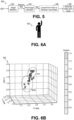
- FIG. 5 shows a flow chart of embodiment method 500 for generating a radar point cloud, according to an embodiment of the present invention.
- Step 304 may be implemented as method 500.
- target detection is performed on an RDI (e.g., received from step 302).
- target detection is performed using constant false alarm rate (CFAR), such as ordered-statistic (OS) CFAR (OS-CFAR).
- CFAR constant false alarm rate
- target detection is performed by comparing each point of the RDI with a predetermined threshold, and selecting the points above the threshold, along with points (e.g., directly adjacent) to the points above the threshold.
- the selection of points includes points in a 5 ⁇ 3 window around each point above the threshold. Other selection mechanisms may also be used.
- the output of step 502 is a masked RDI that includes the selected points and is zero for unselected points.
- step 504 point-angle estimation is performed in a conventional manner for each of the selected points in the masked RDI generated during step 502.
- 2D digital e.g., Barlett
- 2-D Capon 2-D range-angle image
- step 506 a conversion from Polar coordinates to Cartesian coordinates is performed. As will be described in more detail below, the use of Cartesian coordinates may be advantageous for the training of the graph CNN encoder used during step 306. In some embodiments, step 506 is omitted.
- (x,y,z) represent the 3D Cartesian coordinates of the radar point
- ( r, ⁇ ele , ⁇ azi ) represent the 3D Polar coordinates of the radar point
- ⁇ tilt represents the tilt angle of the center of the field-of-view of millimeter-wave radar sensor 102 with respect to the floor
- h represents the height location of the millimeter-wave radar sensor 102 with respect to the floor.
- each detection point includes: 3D coordinates, a signal strength value (indicative of the signal strength of the target located at the 3D coordinates), and a Doppler value (indicative of the level of movement of the target at the 3D coordinates).
- the 3D coordinates are Cartesian coordinates (e.g., x, y, z) (e.g., if step 506 is performed).
- the 3D coordinates are Polar coordinates (e.g., range, azimuth angle, and elevation angle) (e.g., if step 506 is not performed).
- the radar point cloud is represented as a matrix having each of the radar points as columns and each of the (e.g., 5) attributes (e.g., x, y, z, intensity, and Doppler) as rows in a concatenated manner.
- Figures 6A and 6B illustrate, respectively, target 602, and a representation of radar point cloud 620 associated with target 602 and generated using method 500 (including step 506), according to an embodiment of the present invention.
- a human target 602 is standing and lifting his arm.
- different portions of human target 602 are captured with radar points.
- Each radar point has a respective Doppler velocity, which is based on the movement of the particular body part at the time step associated with the radar point cloud 620.
- the body of human target 602 is relatedly still (low Doppler velocity) while the arm exhibits a high Doppler velocity (which is related to the movement associated with the lifting of the arm).
- the neural networks used during method 300 may be trained in a supervised manner, e.g., using a two-step process.
- a first step the graph CNN encoder used during step 306 is trained first (e.g., using information from a camera as the ground truth).
- the neural networks used during steps 308, 316, 318, and 320 are trained in a supervised manner.
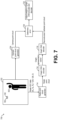
- Figures 7 and 8 illustrate the first and second training steps, respectively.
- Figure 7 illustrates block diagram 700 illustrating a method for training graph CNN encoder 716 (e.g., used during step 306), according to an embodiment of the present invention.
- Block 702 illustrates a scene (e.g., a room) equipped with millimeter-wave radar system 100, a camera system 760, and a human performing various activities (e.g., raising a hand, walking, sitting, falling, etc.). Camera system 760 and millimeter-wave radar system 100 simultaneously capture the same activity of target 602.
- Camera point cloud generator 704 generates a camera point cloud based on an image capture by camera system 760.
- the camera point cloud may be generated in a conventional manner, such as by using the Detectron2 platform from Facebook.
- the number of chirps in a frame N c is 128, the number transmit samples per chirp N s is 64, and the number of receiving antennas 116 R x is 3.
- Radar point cloud generator 714 generates a radar point cloud based on the radar signals captured by millimeter-wave radar system 102 (e.g., at the same time as the image captured by camera system 760). In some embodiments, radar point generator 714 may generate the radar point cloud by performing steps 302 and 304.
- the radar point cloud generated by radar point cloud generator 714 includes, for each point, Cartesian coordinates, which advantageously are easier to compare with the camera point cloud generated by camera point cloud generator 704.
- Graph CNN encoder 716 generates a graph representation vector based on the radar point cloud (e.g., by performing step 306).
- Graph CNN decoder 718 generates a reconstructed Cartesian point cloud based on the graph representation vector generated by graph CNN encoder 716.
- Blocks 720 and 722 illustrate the adjustment of the weights of graph CNN encoder 716 and graph CNN decoder 718 so that the reconstructed Cartesian point cloud approximates the camera point cloud (which is treated as the ground truth).
- the training illustrated by block diagram 700 may be performed frame by frame and, thus, may not include any temporal information.
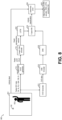
- Figure 8 illustrates block diagram 800 illustrating a method for training CNN encoder 814, DNN 816, LSTM 802, and fusion neural network 818 (e.g., used during steps 316, 318, 308, and 320, respectively), according to an embodiment of the present invention.
- the training illustrated by block diagram 800 assumes that graph CNN encoder 716 is already trained (e.g., using method 700).
- the training illustrated by block diagram 800 is performed per activity. For example, for a particular activity, an activity label and a plurality of frames are produced by block 801. Once fusion neural network 818 produces a prediction of the activity classification, such prediction is compared with the activity label and the weights of the neural networks in blocks 802, 814, 816, and 818 are adjusted to reduced such error (as illustrated by blocks 820 and 822).
- Block 801 illustrates a scene (e.g., a room) equipped with millimeter-wave radar system 100, and a human performing various activities (e.g., raising a hand, walking, sitting, falling, etc.).
- radar point cloud generator 714 generates a radar point cloud based on the radar signals captured by millimeter-wave radar system 102 (e.g., by performing steps 302 and 304) and graph CNN encoder 716 generates a graph representation vector based on the radar point cloud (e.g., by performing step 306).
- Graph representation vectors corresponding to a plurality of frames associated with one activity is provided to (e.g., bidirectional) LSTM 802 (e.g., which is used during step 308).
- CVD generator 812 generates CVD data (e.g., by performing 302 and 314) based on a plurality of frames associated with the one activity. In some embodiments, step 302 shared between radar point cloud generator 714 and CVD generator 812.
- CNN encoder 814 receives the CVD data.
- DNN 816 receives data from an output of CNN encoder 814.
- Fusion NN 818 receives data from an output of LSTM 802 and an output of DNN 816 and generates an activity classification prediction based on the data received from LSTM 802 and DNN 816. Such prediction is compared with the activity label and the weights of the neural networks in blocks 802, 814, 816, and 818 are adjusted to reduced such error (as illustrated by blocks 820 and 822).
- blocks 714, 716, 802, 812, 814, 816, and 818 may be used (e.g., after training) during inference to perform method 300 and produce an activity classification based on the raw data received from millimeter-wave radar sensor 102.
- Blocks 714, 716, 802, 812, 814, 816, and 818 may be implemented by processing system 104.
- Figures 9A and 9B illustrate a possible implementation of graph CNN encoder 716 and graph CNN decoder 718, according to an embodiment of the present invention.
- a radar point cloud (e.g., generated by radar point cloud generator 714) is received by input transformation network 902.
- the dimensionality of the received radar point cloud is n (e.g., 64) times 5 (the 5 features: x, y, z, intensity, and Doppler).
- Input transformation network 902 may be understood as a mini neural network that predicts affine transformation matrix which is applied to the input point clouds, making it invariant to geometric modifications.
- the output of input transformation network 902 is fed to dynamic graph CNN autoencoder 904, which first encodes to produce a graph representation vectors, and then decodes to reconstruct a Cartesian point cloud based on the graph representation vector.
- the EdgeConv block receives a tensor of shape n ⁇ f and computes edge features of each point in k-nearest neighbor (k-nn) graph by a multi-layer perceptron (mlp) with the number of layer units denoted as ⁇ a 1 , a 2 ,..., a n ⁇ .
- graph CNN encoder 716 and graph CNN decoder 718 illustrated in Figures 9A and 9B may be found in the paper entitled " Cross-modal Learning of Graph Representations using Radar Point Cloud for Long-Range Gesture Recognition," by Souvik Hazra, Hao Feng, Gamze Naz Kiprit, Michael Stephan, Lorenzo Servadei, Robert Wille, Robert Weigel, Avik Santra, and published in 2022 by asXiv as 2203.17066 , which is incorporated herein by reference.
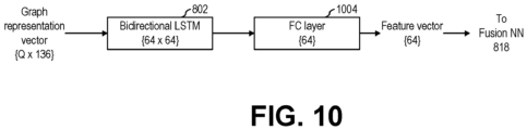
- Figure 10 illustrates block diagram 1000 of a possible implementation of the path from the output of graph CNN encoder 716 to the input of fusion neural network 818, according to an embodiment of the present invention.
- the graph representation vectors generated by graph CNN encoder 716 include 136 dimensions per vector.
- Q vectors (corresponding to Q frames of raw data) are stacked to create a Q ⁇ 136 tensor, which is fed to, e.g., two 64-units bidirectional LSTM layers 802.
- Fully-connected layer 1004 produce a (e.g., 64 dimension) feature vector for activity classification.
- Advantages of some embodiments include the capability of producing accurate activity classification (with, e.g., negligible false positives) at short distances (e.g., less than 1 m) as well as longer distances (e.g., between 1 m and 30 m), which is advantageously superior than some conventional methods that rely on spectrogram, which may have degraded performance beyond 1 m.
- Example 1 A method including: receiving raw data from a millimeter-wave radar sensor; generating a first radar-Doppler image based on the raw data; generating a first radar point cloud based on the first radar-Doppler image; using a graph encoder to generate a first graph representation vector indicative of one or more relationships between two or more parts of the target based on the first radar point cloud; generating a first cadence velocity diagram indicative of a periodicity of movement of one or more parts of the target based on the first radar-Doppler image; and classifying an activity of a target based on the first graph representation vector and the first cadence velocity diagram.
- Example 2 The method of example 1, further including: generating a plurality of graph representation vectors that corresponds to frames of the raw data that are sequential in time, the plurality of graph representation vectors including the first graph representation vector; and providing the plurality of graph representation vectors to a long short-term memory (LSTM) neural network, where classifying the activity of the target is based on an output of the LSTM neural network.
- LSTM long short-term memory
- Example 3 The method of one of examples 1 or 2, further including providing the first cadence velocity diagram to a convolutional neural network (CNN) encoder, where classifying the activity of the target is based on the CNN encoder.
- CNN convolutional neural network
- Example 4 The method of one of examples 1 to 3, further including: providing an output of the CNN encoder to a deep neural network (DNN); providing an output of the DNN to a fusion neural network; and providing the output of the LSTM neural network to the fusion neural network, where classifying the activity of the target is based on an output of the fusion neural network.
- DNN deep neural network
- Example 5 The method of one of examples 1 to 4, where the fusion neural network includes a fully-connected layer.
- Example 6 The method of one of examples 1 to 5, further including training the graph encoder before training the LSTM neural network, the CNN encoder, the DNN, and the fusion neural network.
- Example 7 The method of one of examples 1 to 6, where training the graph encoder includes: generating a first training camera point cloud based on an output of a camera, where the camera has a field of view directed towards a scene, where the millimeter-wave radar sensor has a field of view directed towards the scene; generating a first training radar point cloud based on an output of the millimeter-wave radar sensor, where the first training radar point cloud corresponds to the first training camera point cloud; using the graph encoder to generate a first training graph representation vector based on the first training radar point cloud; using a graph decoder to generate a second training point cloud based on the first training graph representation vector; comparing the first training camera point cloud with the second training point cloud to generate error data; and adjusting one or more weights of the graph encoder based on the error data.
- Example 8 The method of one of examples 1 to 7, where the first radar point cloud includes, for each point of the first radar point cloud, three-dimensional coordinates, an intensity value, and a Doppler value.
- Example 9 The method of one of examples 1 to 8, further including generating a first point-angle image based on the first radar-Doppler image, where generating the first radar point cloud includes generating the first radar point cloud based on the first point-angle image.
- Example 10 The method of one of examples 1 to 9, further including generating a masked first radar-Doppler image from the first radar-Doppler image based on an intensity of each point of the first radar-Doppler image, where generating the first point-angle image includes generating the first point-angle image based on the masked first radar-Doppler image.
- Example 11 The method of one of examples 1 to 10, where generating the masked first radar-Doppler image includes using a constant false alarm rate (CFAR) detector.
- CFAR constant false alarm rate
- Example 12 The method of one of examples 1 to 11, where generating the masked first radar-Doppler image includes: selecting points of the first radar-Doppler image having an intensity higher than a predetermined threshold; and for each selected point, identifying one or more neighboring points in the first radar-Doppler image, where the masked first radar-Doppler image includes the selected points and the identified neighboring points, and where non-selected points and points not identified as neighboring points are not included in the masked first radar-Doppler image.
- Example 13 The method of one of examples 1 to 12, where generating the first point-angle image includes performing Barlett beamforming to transform the first radar-Doppler image to a range-angle image.
- Example 14 The method of one of examples 1 to 13, further including: transmitting radar signals towards a scene including the target; receiving reflected radar signals from the scene; and generating the first radar-Doppler image based on the reflected radar signals.
- Example 15 The method of one of examples 1 to 14, where the target is a person, where the first graph representation vector is indicative of one or more relationships between two or more body parts of the person, where the first cadence velocity diagram is indicative of a periodicity of movement of one or more body parts of the person, and where classifying the activity of the target includes determining whether the person is falling or not falling.
- Example 16 The method of one of examples 1 to 15, where the graph encoder is a graph convolutional neural network (CNN) encoder.
- CNN graph convolutional neural network
- a radar system including: a radar sensor configured to transmit a plurality of radar signals towards a scene, receive a plurality of reflected radar signals from the scene, and generate raw data based on the plurality of reflected radar signals; and a processing system configured to: generate a first radar image based on the raw data, generate a first radar point cloud based on the first radar image, use a graph encoder to generate a first graph representation vector indicative of one or more relationships between two or more parts of the target based on the first radar point cloud, generate a first cadence velocity diagram indicative of a periodicity of movement of one or more parts of the target based on the first radar image, and classify an activity of a target located in the scene based on the first graph representation vector and the first cadence velocity diagram.
- Example 18 The radar system of example 17, where the processing system is further configured to: generate a plurality of graph representation vectors that corresponds to frames of the raw data that are sequential in time, the plurality of graph representation vectors including the first graph representation vector; and provide the plurality of graph representation vectors to a recurrent neural network, where the processing system is configured classify the activity of the target based on an output of the recurrent neural network.
- Example 19 The radar system of one of examples 17 or 18, where the recurrent neural network includes a bi-directional long short-term memory (LSTM) neural network.
- LSTM long short-term memory
- a radar system including: a millimeter-wave radar sensor configured to transmit a plurality of radar signals towards a scene, receive a plurality of reflected radar signals from the scene, and generate raw data based on the plurality of reflected radar signals; and a processing system configured to: generate a plurality of radar-Doppler images based on the raw data, generate a plurality of radar point clouds based on the plurality of radar-Doppler images, use a graph encoder to generate a plurality of graph representation vectors indicative of one or more relationships between two or more parts of the target based on the plurality of radar point clouds, generate a first cadence velocity diagram indicative of a periodicity of movement of one or more parts of the target based on the plurality of radar-Doppler images, and classify an activity of a target located in the scene based on the plurality of graph representation vectors and the first cadence velocity diagram.
Landscapes
- Engineering & Computer Science (AREA)
- Physics & Mathematics (AREA)
- Health & Medical Sciences (AREA)
- Theoretical Computer Science (AREA)
- General Physics & Mathematics (AREA)
- General Health & Medical Sciences (AREA)
- Remote Sensing (AREA)
- Life Sciences & Earth Sciences (AREA)
- Evolutionary Computation (AREA)
- Radar, Positioning & Navigation (AREA)
- Artificial Intelligence (AREA)
- Software Systems (AREA)
- Computer Vision & Pattern Recognition (AREA)
- Computing Systems (AREA)
- Medical Informatics (AREA)
- Multimedia (AREA)
- Biophysics (AREA)
- Molecular Biology (AREA)
- Biomedical Technology (AREA)
- Computer Networks & Wireless Communication (AREA)
- Databases & Information Systems (AREA)
- Mathematical Physics (AREA)
- Psychiatry (AREA)
- Surgery (AREA)
- Public Health (AREA)
- Computational Linguistics (AREA)
- Data Mining & Analysis (AREA)
- Veterinary Medicine (AREA)
- Pathology (AREA)
- Heart & Thoracic Surgery (AREA)
- General Engineering & Computer Science (AREA)
- Animal Behavior & Ethology (AREA)
- Social Psychology (AREA)
- Physiology (AREA)
- Human Computer Interaction (AREA)
- Emergency Management (AREA)
- Gerontology & Geriatric Medicine (AREA)
- Business, Economics & Management (AREA)
- Oral & Maxillofacial Surgery (AREA)
- Dentistry (AREA)
Abstract
Description
- The present disclosure relates generally to an electronic system and method, and, in particular embodiments, to radar-based activity classification.
- Globally, the elderly group (e.g., 65+ years old) is a fast-growing group. Elderly falls account for a significant number of injuries, and many of the injuries are expensive to treat. As a result, elderly fall detection is an active research area.
- It may be desirable for a system to automatically detect a fall of a (e.g., elderly) person (e.g., immediately) after the fall occurs, and trigger an alert so that the person is treated soon after the fall. Such a system may advantageously allow for continuous monitoring of a person, and may allow for prompt detection of a fall. People that may benefit from such a system includes people with dementia and other cognitive and/or physical impairments.
- Elderly fall detection may be performed in various ways. As a field of growing research, many proposals with different sensors have been developed. Popular systems for elderly fall detection include vision systems and wearable systems.
- Vision systems may be used to adequately detect elderly fall detection. However, Vision systems may be expensive, may exhibit low performance in occluded or partially occluded scenarios and low illumination scenarios, and may suffer from privacy concerns.
- Wearable systems may also be used for to adequately detect elderly fall detection. However, wearable systems may be uncomfortable to wear and may restrict the freedom of the person wearing it.
- A method as defined in
claim 1 and a radar system as defined in claim 15 are provided. The dependent claims define further embodiments. - In accordance with an embodiment, a method includes: receiving raw data from a millimeter-wave radar sensor; generating a first radar-Doppler image based on the raw data; generating a first radar point cloud based on the first radar-Doppler image; using a graph encoder to generate a first graph representation vector indicative of one or more relationships between two or more parts of the target based on the first radar point cloud; generating a first cadence velocity diagram indicative of a periodicity of movement of one or more parts of the target based on the first radar-Doppler image; and classifying an activity of a target based on the first graph representation vector and the first cadence velocity diagram.
- In accordance with an embodiment, a radar system includes: a radar sensor configured to transmit a plurality of radar signals towards a scene, receive a plurality of reflected radar signals from the scene, and generate raw data based on the plurality of reflected radar signals; and a processing system configured to: generate a first radar image based on the raw data, generate a first radar point cloud based on the first radar image, use a graph encoder to generate a first graph representation vector indicative of one or more relationships between two or more parts of the target based on the first radar point cloud, generate a first cadence velocity diagram indicative of a periodicity of movement of one or more parts of the target based on the first radar image, and classify an activity of a target located in the scene based on the first graph representation vector and the first cadence velocity diagram.
- In accordance with an embodiment, a radar system includes: a millimeter-wave radar sensor configured to transmit a plurality of radar signals towards a scene, receive a plurality of reflected radar signals from the scene, and generate raw data based on the plurality of reflected radar signals; and a processing system configured to: generate a plurality of radar-Doppler images based on the raw data, generate a plurality of radar point clouds based on the plurality of radar-Doppler images, use a graph encoder to generate a plurality of graph representation vectors indicative of one or more relationships between two or more parts of the target based on the plurality of radar point clouds, generate a first cadence velocity diagram indicative of a periodicity of movement of one or more parts of the target based on the plurality of radar-Doppler images, and classify an activity of a target located in the scene based on the plurality of graph representation vectors and the first cadence velocity diagram.
- For a more complete understanding of the present invention, and the advantages thereof, reference is now made to the following descriptions taken in conjunction with the accompanying drawings, in which:
-
Figure 1 shows a schematic diagram of a millimeter-wave radar system, according to an embodiment of the present invention; -
Figure 2 illustrates a sequence of chirps transmitted by the TX antenna ofFigure 1 , according to an embodiment of the present invention; -
Figure 3 shows an embodiment method for activity classification of a target, according to an embodiment of the present invention; -
Figure 4 shows a flow chart of an embodiment method for generating an RDI, according to an embodiment of the present invention; -
Figure 5 shows a flow chart of an embodiment method for generating a radar point cloud, according to an embodiment of the present invention; -
Figures 6A and 6B illustrate, respectively, a target, and a representation of a radar point cloud associated with the target and generated using the method ofFigure 5 , according to an embodiment of the present invention; -
Figure 7 shows a block diagram illustrating a method for training a graph CNNencoder 716, according to an embodiment of the present invention; -
Figure 8 illustrates a block diagram illustrating a method for training various neural networks used during the method ofFigure 3 , according to an embodiment of the present invention; -
Figures 9A and 9B illustrate a possible implementation of the graph CNN encoder and decoder ofFigure 7 , according to an embodiment of the present invention; and -
Figure 10 illustrates a block diagram of a possible implementation of the path from the output of the graph CNN encoder ofFigure 7 to the input of the fusion neural network ofFigure 8 , according to an embodiment of the present invention. - Corresponding numerals and symbols in different figures generally refer to corresponding parts unless otherwise indicated. The figures are drawn to clearly illustrate the relevant aspects of the preferred embodiments and are not necessarily drawn to scale.
- The making and using of the embodiments disclosed are discussed in detail below. It should be appreciated, however, that the present invention provides many applicable inventive concepts that can be embodied in a wide variety of specific contexts. The specific embodiments discussed are merely illustrative of specific ways to make and use the invention, and do not limit the scope of the invention.
- The description below illustrates the various specific details to provide an in-depth understanding of several example embodiments according to the description. The embodiments may be obtained without one or more of the specific details, or with other methods, components, materials and the like. In other cases, known structures, materials or operations are not shown or described in detail so as not to obscure the different aspects of the embodiments. References to "an embodiment" in this description indicate that a particular configuration, structure or feature described in relation to the embodiment is included in at least one embodiment. Consequently, phrases such as "in one embodiment" that may appear at different points of the present description do not necessarily refer exactly to the same embodiment. Furthermore, specific formations, structures or features may be combined in any appropriate manner in one or more embodiments.
- Embodiments of the present invention will be described in specific contexts, e.g., a radar-based activity classification system and method, e.g., for elderly fall detection. Embodiments of the present invention may be used for other types of activity classification, such as classifying various human activities (sitting, standing, walking, running, bending over, stretching, etc.), gesture recognition, etc.
- Radar-based systems for elderly fall detection have many advantages. Advantages of radar-based systems for elderly fall detection may include: lower cost than vision systems, little or no privacy concerns, less susceptible to a decrease in performance in occluded or partially occluded scenarios and low illumination scenarios, and allowing freedom of movement to the user.
- It may be challenging for a radar-based system to distinguish between some activities and a fall. For example, a person sitting down or bent over to pick up something may be mistakenly detected as a fall, thereby causing false positives.
- In an embodiment of the present invention, a millimeter-wave radar system is advantageously able to distinguish between similar activities of a target (e.g., a person sitting down versus falling) and, thus, reduce the number of false positives, by encoding a radar point cloud using a graph encoder to obtain graph representation vectors indicative of relationships between different body parts during an activity of the target. In parallel, a cadence-velocity diagram (CVD) is used to extract information about the periodicity of movement of different body parts during the activity of the target. Information from the CVD and the graph representation vectors is used to classify the activity of the target (e.g., a person falling or not falling).
-
Figure 1 shows a schematic diagram of millimeter-wave radar system 100, according to an embodiment of the present invention. Millimeter-wave radar system 100 includes millimeter-wave radar sensor 102 andprocessing system 104. - During normal operation, millimeter-
wave radar sensor 102 operates as a frequency-modulated continuous-wave (FMCW) radar sensor and transmits a plurality ofTX radar signals 106, such as chirps, towardsscene 120 using one or more transmitter (TX)antenna 114. Theradar signals 106 are generated using RF andanalog circuits 130. Theradar signals 106 may be, e.g., in the 20 GHz to 122 GHz range. Other frequencies may also be used. - The objects in
scene 120 may include one or more static or moving objects, such as tables, walls, chairs, etc., idle and moving humans and animals, as well as periodically-moving objects, such as rotating fans. Other objects may also be present inscene 120. - The
radar signals 106 are reflected by objects inscene 120. Thereflected radar signals 108, which are also referred to as the echo signal, are received by a plurality of receiving (RX)antennas 116. RF andanalog circuits 130 processes the received reflected radar signals 108 using, e.g., band-pass filters (BPFs), low-pass filters (LPFs), mixers, low-noise amplifier (LNA), and/or intermediate frequency (IF) amplifiers in ways known in the art to generate an analog signal xout (t) per receivingantenna 116. - The analog signals xout (t) are converted to raw digital data xout_dig (n) using analog-to-digital converter (ADC) 112. In some embodiments, the raw digital data xout_dig (n) is processed by processing
system 104 to detect one or more targets and their position, track such targets, and classify the activity of such targets. -
Controller 110 controls one or more circuits of millimeter-wave radar sensor 102, such as RF andanalog circuit 130 and/orADC 112.Controller 110 may be implemented, e.g., as a custom digital or mixed signal circuit, for example.Controller 110 may also be implemented in other ways, such as using a general-purpose processor or controller, for example. In some embodiments,processing system 104 implements a portion or all ofcontroller 110. -
Processing system 104 may be implemented with a general-purpose processor, controller or digital signal processor (DSP) that includes, for example, combinatorial circuits coupled to a memory. In some embodiments,processing system 104 may be implemented as an application specific integrated circuit (ASIC). In some embodiments,processing system 104 may be implemented with an ARM, RISC, or x86 architecture, for example. In some embodiments,processing system 104 may include an artificial intelligence (AI) accelerator. Some embodiments may use a combination of hardware accelerator and software running on a DSP or general-purpose microcontroller. Other implementations are also possible. - In some embodiments, millimeter-
wave radar sensor 102 and a portion or all ofprocessing system 104 may be implemented inside the same integrated circuit (IC). For example, in some embodiments, millimeter-wave radar sensor 102 and a portion or all ofprocessing system 104 may be implemented in respective semiconductor substrates that are integrated in the same package. In other embodiments, millimeter-wave radar sensor 102 and a portion or all ofprocessing system 104 may be implemented in the same monolithic semiconductor substrate. In some embodiments, millimeter-wave radar sensor 102 andprocessing system 104 are implemented in respective integrated circuits. In some embodiments, a plurality of integrated circuits is used to implement millimeter-wave radar sensor 102. In some embodiments, a plurality of integrated circuits is used to implementprocessing system 104. Other implementations are also possible. - As a non-limiting example, RF and
analog circuits 130 may be implemented, e.g., as shown inFigure 1 . During normal operation, voltage-controlled oscillator (VCO) 136 generates radar signals, such as a linear frequency chirps (e.g., from 57 GHz to 64 GHz, or from 76 GHz to 77 GHz), which are transmitted by transmittingantenna 114. TheVCO 136 is controlled byPLL 134, which receives a reference clock signal (e.g., 80 MHz) fromreference oscillator 132.PLL 134 is controlled by a loop that includesfrequency divider 138 andamplifier 140.Amplifier 137 may be used to drive transmittingantenna 114. - The TX radar signals 106 transmitted by transmitting
antenna 114 are reflected by objects inscene 120 and received by receivingantennas 116. The echo received by receivingantennas 116 are mixed with a replica of the signal transmitted by transmittingantenna 114 usingrespective mixers 146 to produce respective intermediate frequency (IF) signals xIF (t) (also known as beat signals). In some embodiments, the beat signals xIF (t) have a bandwidth between 10 kHz and 1 MHz. Beat signals with a bandwidth lower than 10 kHz or higher than 1 MHz is also possible. Respective amplifiers 145 may be used to receive the reflected radar signals fromantennas 116. - Beat signals xIF (t) may be respectively filtered with respective low-pass filters (LPFs) 148 and then sampled by
ADC 112.ADC 112 is advantageously capable of sampling the filtered beat signals xout (t) with a sampling frequency that is much smaller than the frequency of the signal received by receivingantennas 116. Using FMCW radars, therefore, advantageously allows for a compact and low-cost implementation ofADC 112, in some embodiments. - The raw digital data xout_dig (n), which in some embodiments include the digitized version of the filtered beat signals xout (t), is (e.g., temporarily) stored, e.g., in matrices of Nc x Ns per receiving
antenna 116, where Nc is the number of chirps considered in a frame and Ns is the number of transmit samples per chirp, for further processing byprocessing system 104. - In some embodiments,
ADC 112 is a 12-bit ADC with multiple inputs. ADCs with higher resolution, such as 14-bits or higher, or with lower resolution, such as 10-bits, or lower, may also be used. In some embodiments, an ADC per receiver antenna may be used. Other implementations are also possible. -
Figure 2 illustrates a sequence ofchirps 106 transmitted byTX antenna 114, according to an embodiment of the present invention. As shown byFigure 2 , chirps 106 are organized in a plurality of frames (also referred to as physical frames) and may be implemented as up-chirps. Some embodiments may use down-chirps or a combination of up-chirps and down-chirps, such as up-down chirps and down-up chirps. Other waveform shapes may also be used. - As shown in
Figure 2 , each frame may include a plurality of chirps 106 (also referred to, generally, as pulses). For example, in some embodiments, the number of chirps in a frame is 64. - Some embodiments may include more than 64 chirps per frame, such as 96 chirps, 128 chirps, 256 chirps, or more, or less than 64 chirps per frame, such as 32 chirps, 16 chirps, or less.
- In some embodiments, frames are repeated every FT time. In some embodiments, FT time is 50 ms. A different FT time may also be used, such as more than 50 ms, such as 60 ms, 100 ms, 200 ms, or more, or less than 50 ms, such as 45 ms, 40 ms, or less.
- In some embodiments, the FT time is selected such that the time between the beginning of the last chirp of frame n and the beginning of the first chirp of frame n+1 is equal to PRT. Other embodiments may use or result in a different timing.
- The time between chirps of a frame is generally referred to as pulse repetition time (PRT). In some embodiments, the PRT is 5 ms. A different PRT may also be used, such as less than 5 ms, such as 4 ms, 2 ms, 0.5 ms, or less, or more than 5 ms, such as 6 ms, or more.
- The duration of the chirp (from start to finish) is generally referred to as chirp time (CT). In some embodiments, the chirp time may be, e.g., 64 µs. Higher chirp times, such as 128 µs, or higher, may also be used. Lower chirp times, may also be used.
- In some embodiments, the chirp bandwidth may be, e.g., 4 GHz. Higher bandwidth, such as 6 GHz or higher, or lower bandwidth, such as 2 GHz, 1 GHz, or lower, may also be possible.
- In some embodiments, the sampling frequency of millimeter-
wave radar sensor 102 may be, e.g., 1 MHz. Higher sampling frequencies, such as 2 MHz or higher, or lower sampling frequencies, such as 500 kHz or lower, may also be possible. - In some embodiments, the number of samples used to generate each chirp may be, e.g., 64 samples. A higher number of samples, such as 128 samples, or higher, or a lower number of samples, such as 32 samples or lower, may also be used to generate each chirp.
-
Figure 3 showsembodiment method 300 for activity classification of a target, according to an embodiment of the present invention.Method 300 may be implemented by processingsystem 104. -
Method 300 includessteps steps including steps steps including steps - In some embodiments,
steps - During
step 302, a range-Doppler image (RDI) is generated based on raw data (e.g., Xout_dig(n)) received from, e.g., millimeter-wave radar sensor 102. In some embodiments, the RDI may be generated in a conventional manner. - During
step 304, a radar point cloud is generated. A radar point cloud may be understood as a scattered collection of points that represent one or more targets in a scene. In some embodiments, the radar point cloud includes, for each point of the radar point cloud, three-dimensional (3D) coordinates (e.g., Cartesian or Polar), an intensity value, and Doppler value. - During
step 306, a graph encoder, such as a graph convolutional neural network (CNN) encoder, is used to generate a graph representation vector based on the radar point cloud (e.g., a graph representation of the radar point cloud) generated duringstep 304. In some embodiments, the graph representation vector includes additional edge information (e.g., edge weight) connecting each of the nodes (points of the radar point cloud) to each other. Such edge information may advantageously allow for extracting relationship values between points of the radar point cloud that may not be spatially adjacent (e.g., extracting a relationship value between points with 3D coordinates that are relatively far away, such as a point representing a hand and a point representing a foot). In some embodiments, such relationship values may advantageously aid in differentiating activities that may be similar. For example, even though the motion of a person falling and a person bending over to pick something may be similar, a person falling may exhibit uncontrolled limb motions while a person bending over may exhibit controlled limb motion. Such difference in limb motions may be used to distinguish between otherwise similar activities. - In some embodiments,
steps - During
step 308, a (e.g., bidirectional) long short-term memory (LSTM) neural network is used (e.g., after training) to (e.g., generate feature vectors and) classify the (e.g., sequential in time) the graph representation vectors generated duringstep 306. In some embodiments, temporal information is extracted from the graph representation vectors by using graph representation vectors that correspond to radar point clouds that are sequential in time. For example, in some embodiments, a plurality of RDIs that are sequential in time are generated duringstep 302, which cause the generation of a corresponding plurality of radar point clouds that are sequential in time (during step 308), which cause the graph representation vectors generated duringstep 306 to be sequential in time. Such graph representation vectors may be provided to the LSTM duringstep 308. The LSTM used duringstep 308 may be implemented in a conventional manner. - As a non-limiting example, in some embodiments, N radar point clouds that are sequential in time are generated during
step 304 based on N sequential in time RDIs generated during step 302 (which are generated based on N sequential frames of raw data, where each frame of raw data is associated with a respective time step). A corresponding N graph representation vectors are generated duringstep 306 based on the N radar point clouds. - In some embodiments, N may be equal to 10. N having values higher than 10, such as 12, 16, or more, or N having values lower than 10, such as 8 or lower, may also be used.
- During
step 314, a cadence velocity diagram (CVD) is generated based on the RDI generated duringstep 302. A CVD may be understood as a diagram that expresses how the curves in the time-frequency-domain repeat. For example, in some embodiments, for N sequential RDIs generated duringstep 302, a Doppler bin is selected (e.g., such as the Doppler bin exhibiting highest intensity), the selected Doppler bins are stacked together, and an FFT is performed on the stacked Doppler bins to generated the CVD. In some embodiments, the resulting CVD captures the periodicity of movement of different body parts during the N time steps. - During
step 316, a CNN encoder is used to generate a feature map based on the CVD. Such feature map is used duringstep 318 by a neural network, such as a deep neural network (DNN) to generate a feature vector. - In some embodiments, the CNN encoder used during
step 316 may be implemented in a conventional manner. In some embodiments, the DNN used duringstep 318 may be implemented in a conventional manner. - In some embodiments, the neural network used during
step 318 may include one or more fully-connected layers and/or a 1D CNN. - During
step 320, a fusion neural network, which may include one or more fully-connected layers, is used to generate an activity classification based on the feature vectors generated duringsteps step 320 may include just two activities (L=2), representing the activities of, e.g., a target falling or not falling. In some embodiments, the activity classification generated duringstep 320 may include more than two activities (L > 2), representing more than two activities, such as walking, running, sitting, bending over, and falling. Other implementations are also possible. - In some embodiments, in a particular classification cycle (for a particular output of the fusion NN during step 320), the number of time steps N used for generating the CVD data during
step 314 is the same and correspond to the time steps used duringstep 308 by the LSTM neural network. -
Figure 4 shows a flow chart ofembodiment method 400 for generating an RDI, according to an embodiment of the present invention. Step 302 may be implemented asmethod 400. - During
step 402, a range fast Fourier transform (FFT) is performed on the raw digital data xout_dig (n) (e.g., on data from each receiving channel, e.g., from each receiving antenna 116). For example, in some embodiments, a windowed FFT having a length of a chirp (e.g., 106) is calculated for each of a predetermined number of chirps (e.g., all chirps) in a frame. The result of the range FFT is an indication of energy distribution across ranges for each chirp. - During
step 404, a Doppler FFT is performed on the range FFT data (e.g., for each receiving antenna 116) generated duringstep 402. For example, in some embodiments, an FFT is calculated across each range bin over a number of consecutive periods to extract Doppler information. The result ofstep 404 are range Doppler maps (also known are range-Doppler images or RDIs) for each of the receiving channels (e.g., for each receiving antenna 116). - During
step 406, two-dimensional (2D) moving target indication (MTI) filtering is applied to each RDI to generate first filtered images. In some embodiments, performing MTI filtering serves to discriminate a target against the clutter. For example, in some embodiments, after MTI filtering is performed on the RDIs, only targets with high motion are retained as their energy varies across Doppler images. Thus, in some embodiments, after 2D MTI filtering, a target may be identifiable in the filtered RDIs while information about the background may be partially or fully removed from the filtered RDIs. In some embodiments, the 2D MTI filter is implemented as a first order finite impulse response (FIR) filter. - In some embodiments, only single person scenarios are considered. Thus, in some embodiments, outlier points (points far from the cluster of points) are removed as noise during
step 408. - In some embodiments,
method 400 is performed for each frame of raw data x out_dig (n), thereby generating an RDI per frame of raw data xout_dig (n). -
Figure 5 shows a flow chart ofembodiment method 500 for generating a radar point cloud, according to an embodiment of the present invention. Step 304 may be implemented asmethod 500. - During
step 502, target detection is performed on an RDI (e.g., received from step 302). In some embodiments, target detection is performed using constant false alarm rate (CFAR), such as ordered-statistic (OS) CFAR (OS-CFAR). - In some embodiments, target detection is performed by comparing each point of the RDI with a predetermined threshold, and selecting the points above the threshold, along with points (e.g., directly adjacent) to the points above the threshold. In some embodiments, the selection of points includes points in a 5×3 window around each point above the threshold. Other selection mechanisms may also be used.
- The output of
step 502 is a masked RDI that includes the selected points and is zero for unselected points. - During
step 504, point-angle estimation is performed in a conventional manner for each of the selected points in the masked RDI generated duringstep 502. For example, in some embodiments, 2D digital (e.g., Barlett) beamforming (e.g., 2-D Capon) is applied to transform the data across virtual channels from rectangular array configuration into 2-D range-angle image (RAI). - During
step 506, a conversion from Polar coordinates to Cartesian coordinates is performed. As will be described in more detail below, the use of Cartesian coordinates may be advantageous for the training of the graph CNN encoder used duringstep 306. In some embodiments,step 506 is omitted. - In some embodiments, the conversion from Polar coordinates to Cartesian coordinates may be performed by using Equation 1:

wave radar sensor 102 with respect to the floor, and h represents the height location of the millimeter-wave radar sensor 102 with respect to the floor. - During
step 508, a set of detection points is generated, which together form the radar point cloud. In some embodiments, each detection point includes: 3D coordinates, a signal strength value (indicative of the signal strength of the target located at the 3D coordinates), and a Doppler value (indicative of the level of movement of the target at the 3D coordinates). In some embodiments, the 3D coordinates are Cartesian coordinates (e.g., x, y, z) (e.g., ifstep 506 is performed). In some embodiments, the 3D coordinates are Polar coordinates (e.g., range, azimuth angle, and elevation angle) (e.g., ifstep 506 is not performed). - In some embodiments, the radar point cloud is represented as a matrix having each of the radar points as columns and each of the (e.g., 5) attributes (e.g., x, y, z, intensity, and Doppler) as rows in a concatenated manner.
-
Figures 6A and 6B illustrate, respectively,target 602, and a representation ofradar point cloud 620 associated withtarget 602 and generated using method 500 (including step 506), according to an embodiment of the present invention. - As shown in
Figure 6A , ahuman target 602 is standing and lifting his arm. As shown inFigure 6B , different portions ofhuman target 602 are captured with radar points. Each radar point has a respective Doppler velocity, which is based on the movement of the particular body part at the time step associated with theradar point cloud 620. - As illustrated in
Figure 6B , the body ofhuman target 602 is relatedly still (low Doppler velocity) while the arm exhibits a high Doppler velocity (which is related to the movement associated with the lifting of the arm). - In some embodiments, the neural networks used during
method 300 may be trained in a supervised manner, e.g., using a two-step process. In a first step, the graph CNN encoder used duringstep 306 is trained first (e.g., using information from a camera as the ground truth). Once the graph CNN encoder is trained, the neural networks used duringsteps Figures 7 and8 illustrate the first and second training steps, respectively. -
Figure 7 illustrates block diagram 700 illustrating a method for training graph CNN encoder 716 (e.g., used during step 306), according to an embodiment of the present invention. -
Block 702 illustrates a scene (e.g., a room) equipped with millimeter-wave radar system 100, acamera system 760, and a human performing various activities (e.g., raising a hand, walking, sitting, falling, etc.).Camera system 760 and millimeter-wave radar system 100 simultaneously capture the same activity oftarget 602. - Camera
point cloud generator 704 generates a camera point cloud based on an image capture bycamera system 760. The camera point cloud may be generated in a conventional manner, such as by using the Detectron2 platform from Facebook. - As illustrated in
Figure 7 , in some embodiments, the number of chirps in a frame Nc is 128, the number transmit samples per chirp Ns is 64, and the number of receiving antennas 116 Rx is 3. - Radar
point cloud generator 714 generates a radar point cloud based on the radar signals captured by millimeter-wave radar system 102 (e.g., at the same time as the image captured by camera system 760). In some embodiments,radar point generator 714 may generate the radar point cloud by performingsteps - In some embodiments, the radar point cloud generated by radar
point cloud generator 714 includes, for each point, Cartesian coordinates, which advantageously are easier to compare with the camera point cloud generated by camerapoint cloud generator 704. -
Graph CNN encoder 716 generates a graph representation vector based on the radar point cloud (e.g., by performing step 306). -
Graph CNN decoder 718 generates a reconstructed Cartesian point cloud based on the graph representation vector generated bygraph CNN encoder 716. -
Blocks graph CNN encoder 716 andgraph CNN decoder 718 so that the reconstructed Cartesian point cloud approximates the camera point cloud (which is treated as the ground truth). - In some embodiments, the training illustrated by block diagram 700 may be performed frame by frame and, thus, may not include any temporal information.
-
Figure 8 illustrates block diagram 800 illustrating a method for trainingCNN encoder 814,DNN 816,LSTM 802, and fusion neural network 818 (e.g., used duringsteps - The training illustrated by block diagram 800 assumes that
graph CNN encoder 716 is already trained (e.g., using method 700). - In some embodiments, the training illustrated by block diagram 800 is performed per activity. For example, for a particular activity, an activity label and a plurality of frames are produced by
block 801. Once fusionneural network 818 produces a prediction of the activity classification, such prediction is compared with the activity label and the weights of the neural networks inblocks blocks 820 and 822). -
Block 801 illustrates a scene (e.g., a room) equipped with millimeter-wave radar system 100, and a human performing various activities (e.g., raising a hand, walking, sitting, falling, etc.). - In a similar manner as described with respect to
Figure 7 , radarpoint cloud generator 714 generates a radar point cloud based on the radar signals captured by millimeter-wave radar system 102 (e.g., by performingsteps 302 and 304) andgraph CNN encoder 716 generates a graph representation vector based on the radar point cloud (e.g., by performing step 306). - Graph representation vectors corresponding to a plurality of frames associated with one activity is provided to (e.g., bidirectional) LSTM 802 (e.g., which is used during step 308).
-
CVD generator 812 generates CVD data (e.g., by performing 302 and 314) based on a plurality of frames associated with the one activity. In some embodiments, step 302 shared between radarpoint cloud generator 714 andCVD generator 812. -
CNN encoder 814 receives the CVD data.DNN 816 receives data from an output ofCNN encoder 814.Fusion NN 818 receives data from an output ofLSTM 802 and an output ofDNN 816 and generates an activity classification prediction based on the data received fromLSTM 802 andDNN 816. Such prediction is compared with the activity label and the weights of the neural networks inblocks blocks 820 and 822). - In some embodiments, blocks 714, 716, 802, 812, 814, 816, and 818 may be used (e.g., after training) during inference to perform
method 300 and produce an activity classification based on the raw data received from millimeter-wave radar sensor 102.Blocks system 104. -
Figures 9A and 9B illustrate a possible implementation ofgraph CNN encoder 716 andgraph CNN decoder 718, according to an embodiment of the present invention. - As shown in
Figure 9A , a radar point cloud (e.g., generated by radar point cloud generator 714) is received byinput transformation network 902. As shown, the dimensionality of the received radar point cloud is n (e.g., 64) times 5 (the 5 features: x, y, z, intensity, and Doppler). -
Input transformation network 902 may be understood as a mini neural network that predicts affine transformation matrix which is applied to the input point clouds, making it invariant to geometric modifications. - The output of
input transformation network 902 is fed to dynamicgraph CNN autoencoder 904, which first encodes to produce a graph representation vectors, and then decodes to reconstruct a Cartesian point cloud based on the graph representation vector. - As shown in
Figure 9B , the EdgeConv block receives a tensor of shape n × f and computes edge features of each point in k-nearest neighbor (k-nn) graph by a multi-layer perceptron (mlp) with the number of layer units denoted as {a1, a2,..., an}. - Additional details of the operation and structure of
graph CNN encoder 716 andgraph CNN decoder 718 illustrated inFigures 9A and 9B may be found in the paper entitled "Cross-modal Learning of Graph Representations using Radar Point Cloud for Long-Range Gesture Recognition," by Souvik Hazra, Hao Feng, Gamze Naz Kiprit, Michael Stephan, Lorenzo Servadei, Robert Wille, Robert Weigel, Avik Santra, and published in 2022 by asXiv as 2203.17066, which is incorporated herein by reference. -
Figure 10 illustrates block diagram 1000 of a possible implementation of the path from the output of graph CNN encoder 716 to the input of fusionneural network 818, according to an embodiment of the present invention. - As shown in
Figure 10 , in some embodiments, the graph representation vectors generated bygraph CNN encoder 716 include 136 dimensions per vector. Q vectors (corresponding to Q frames of raw data) are stacked to create a Q × 136 tensor, which is fed to, e.g., two 64-units bidirectional LSTM layers 802. Fully-connectedlayer 1004 produce a (e.g., 64 dimension) feature vector for activity classification. - Advantages of some embodiments include the capability of producing accurate activity classification (with, e.g., negligible false positives) at short distances (e.g., less than 1 m) as well as longer distances (e.g., between 1 m and 30 m), which is advantageously superior than some conventional methods that rely on spectrogram, which may have degraded performance beyond 1 m.
- Example embodiments of the present invention are summarized here. Other embodiments can also be understood from the entirety of the specification and the claims filed herein.
- Example 1. A method including: receiving raw data from a millimeter-wave radar sensor; generating a first radar-Doppler image based on the raw data; generating a first radar point cloud based on the first radar-Doppler image; using a graph encoder to generate a first graph representation vector indicative of one or more relationships between two or more parts of the target based on the first radar point cloud; generating a first cadence velocity diagram indicative of a periodicity of movement of one or more parts of the target based on the first radar-Doppler image; and classifying an activity of a target based on the first graph representation vector and the first cadence velocity diagram.
- Example 2. The method of example 1, further including: generating a plurality of graph representation vectors that corresponds to frames of the raw data that are sequential in time, the plurality of graph representation vectors including the first graph representation vector; and providing the plurality of graph representation vectors to a long short-term memory (LSTM) neural network, where classifying the activity of the target is based on an output of the LSTM neural network.
- Example 3. The method of one of examples 1 or 2, further including providing the first cadence velocity diagram to a convolutional neural network (CNN) encoder, where classifying the activity of the target is based on the CNN encoder.
- Example 4. The method of one of examples 1 to 3, further including: providing an output of the CNN encoder to a deep neural network (DNN); providing an output of the DNN to a fusion neural network; and providing the output of the LSTM neural network to the fusion neural network, where classifying the activity of the target is based on an output of the fusion neural network.
- Example 5. The method of one of examples 1 to 4, where the fusion neural network includes a fully-connected layer.
- Example 6. The method of one of examples 1 to 5, further including training the graph encoder before training the LSTM neural network, the CNN encoder, the DNN, and the fusion neural network.
- Example 7. The method of one of examples 1 to 6, where training the graph encoder includes: generating a first training camera point cloud based on an output of a camera, where the camera has a field of view directed towards a scene, where the millimeter-wave radar sensor has a field of view directed towards the scene; generating a first training radar point cloud based on an output of the millimeter-wave radar sensor, where the first training radar point cloud corresponds to the first training camera point cloud; using the graph encoder to generate a first training graph representation vector based on the first training radar point cloud; using a graph decoder to generate a second training point cloud based on the first training graph representation vector; comparing the first training camera point cloud with the second training point cloud to generate error data; and adjusting one or more weights of the graph encoder based on the error data.
- Example 8. The method of one of examples 1 to 7, where the first radar point cloud includes, for each point of the first radar point cloud, three-dimensional coordinates, an intensity value, and a Doppler value.
- Example 9. The method of one of examples 1 to 8, further including generating a first point-angle image based on the first radar-Doppler image, where generating the first radar point cloud includes generating the first radar point cloud based on the first point-angle image.
- Example 10. The method of one of examples 1 to 9, further including generating a masked first radar-Doppler image from the first radar-Doppler image based on an intensity of each point of the first radar-Doppler image, where generating the first point-angle image includes generating the first point-angle image based on the masked first radar-Doppler image.
- Example 11. The method of one of examples 1 to 10, where generating the masked first radar-Doppler image includes using a constant false alarm rate (CFAR) detector.
- Example 12. The method of one of examples 1 to 11, where generating the masked first radar-Doppler image includes: selecting points of the first radar-Doppler image having an intensity higher than a predetermined threshold; and for each selected point, identifying one or more neighboring points in the first radar-Doppler image, where the masked first radar-Doppler image includes the selected points and the identified neighboring points, and where non-selected points and points not identified as neighboring points are not included in the masked first radar-Doppler image.
- Example 13. The method of one of examples 1 to 12, where generating the first point-angle image includes performing Barlett beamforming to transform the first radar-Doppler image to a range-angle image.
- Example 14. The method of one of examples 1 to 13, further including: transmitting radar signals towards a scene including the target; receiving reflected radar signals from the scene; and generating the first radar-Doppler image based on the reflected radar signals.
- Example 15. The method of one of examples 1 to 14, where the target is a person, where the first graph representation vector is indicative of one or more relationships between two or more body parts of the person, where the first cadence velocity diagram is indicative of a periodicity of movement of one or more body parts of the person, and where classifying the activity of the target includes determining whether the person is falling or not falling.
- Example 16. The method of one of examples 1 to 15, where the graph encoder is a graph convolutional neural network (CNN) encoder.
- Example 17. A radar system including: a radar sensor configured to transmit a plurality of radar signals towards a scene, receive a plurality of reflected radar signals from the scene, and generate raw data based on the plurality of reflected radar signals; and a processing system configured to: generate a first radar image based on the raw data, generate a first radar point cloud based on the first radar image, use a graph encoder to generate a first graph representation vector indicative of one or more relationships between two or more parts of the target based on the first radar point cloud, generate a first cadence velocity diagram indicative of a periodicity of movement of one or more parts of the target based on the first radar image, and classify an activity of a target located in the scene based on the first graph representation vector and the first cadence velocity diagram.
- Example 18. The radar system of example 17, where the processing system is further configured to: generate a plurality of graph representation vectors that corresponds to frames of the raw data that are sequential in time, the plurality of graph representation vectors including the first graph representation vector; and provide the plurality of graph representation vectors to a recurrent neural network, where the processing system is configured classify the activity of the target based on an output of the recurrent neural network.
- Example 19. The radar system of one of examples 17 or 18, where the recurrent neural network includes a bi-directional long short-term memory (LSTM) neural network.
- Example 20. A radar system including: a millimeter-wave radar sensor configured to transmit a plurality of radar signals towards a scene, receive a plurality of reflected radar signals from the scene, and generate raw data based on the plurality of reflected radar signals; and a processing system configured to: generate a plurality of radar-Doppler images based on the raw data, generate a plurality of radar point clouds based on the plurality of radar-Doppler images, use a graph encoder to generate a plurality of graph representation vectors indicative of one or more relationships between two or more parts of the target based on the plurality of radar point clouds, generate a first cadence velocity diagram indicative of a periodicity of movement of one or more parts of the target based on the plurality of radar-Doppler images, and classify an activity of a target located in the scene based on the plurality of graph representation vectors and the first cadence velocity diagram.
- While this invention has been described with reference to illustrative embodiments, this description is not intended to be construed in a limiting sense. Various modifications and combinations of the illustrative embodiments, as well as other embodiments of the invention, will be apparent to persons skilled in the art upon reference to the description. It is therefore intended that the appended claims encompass any such modifications or embodiments.
Claims (15)
- A method comprising:receiving raw data from a millimeter-wave radar sensor;generating a first radar-Doppler image based on the raw data;generating a first radar point cloud based on the first radar-Doppler image;using a graph encoder to generate a first graph representation vector indicative of one or more relationships between two or more parts of the target based on the first radar point cloud;generating a first cadence velocity diagram indicative of a periodicity of movement of one or more parts of the target based on the first radar-Doppler image; andclassifying an activity of a target based on the first graph representation vector and the first cadence velocity diagram.
- The method of claim 1, further comprising:generating a plurality of graph representation vectors that corresponds to frames of the raw data that are sequential in time, the plurality of graph representation vectors comprising the first graph representation vector; andproviding the plurality of graph representation vectors to a long short-term memory neural network, wherein classifying the activity of the target is based on an output of the long short-term memory neural network.
- The method of claim 2, further comprising providing the first cadence velocity diagram to a convolutional neural network encoder, wherein classifying the activity of the target is based on the convolutional neural network encoder.
- The method of claim 3, further comprising:providing an output of the convolutional neural network encoder to a deep neural network;providing an output of the deep neural network to a fusion neural network; andproviding the output of the long short-term memory neural network to the fusion neural network, wherein classifying the activity of the target is based on an output of the fusion neural network.
- The method of claim 4, further comprising training the graph encoder before training the long short-term memory neural network, the convolutional neural network encoder, the deep neural network, and the fusion neural network.
- The method of claim 5, wherein training the graph encoder comprises:generating a first training camera point cloud based on an output of a camera, wherein the camera has a field of view directed towards a scene, wherein the millimeter-wave radar sensor has a field of view directed towards the scene;generating a first training radar point cloud based on an output of the millimeter-wave radar sensor, wherein the first training radar point cloud corresponds to the first training camera point cloud;using the graph encoder to generate a first training graph representation vector based on the first training radar point cloud;using a graph decoder to generate a second training point cloud based on the first training graph representation vector;comparing the first training camera point cloud with the second training point cloud to generate error data; andadjusting one or more weights of the graph encoder based on the error data.
- The method of any one of claims 1 to 6, wherein the first radar point cloud comprises, for each point of the first radar point cloud, three-dimensional coordinates, an intensity value, and a Doppler value.
- The method of any one of claims 1 to 7, further comprising generating a first point-angle image based on the first radar-Doppler image, wherein generating the first radar point cloud comprises generating the first radar point cloud based on the first point-angle image.
- The method of claim 8, further comprising generating a masked first radar-Doppler image from the first radar-Doppler image based on an intensity of each point of the first radar-Doppler image, wherein generating the first point-angle image comprises generating the first point-angle image based on the masked first radar-Doppler image.
- The method of claim 9, wherein generating the masked first radar-Doppler image comprises using a constant false alarm rate detector.
- The method of claim 9 or 10, wherein generating the masked first radar-Doppler image comprises:selecting points of the first radar-Doppler image having an intensity higher than a predetermined threshold; andfor each selected point, identifying one or more neighboring points in the first radar-Doppler image, wherein the masked first radar-Doppler image comprises the selected points and the identified neighboring points, and wherein non-selected points and points not identified as neighboring points are not comprised in the masked first radar-Doppler image.
- The method of any one of claims 8 to 11, wherein generating the first point-angle image comprises performing Barlett beamforming to transform the first radar-Doppler image to a range-angle image.
- The method of any one of claims 1 to 12, further comprising:transmitting radar signals towards a scene comprising the target;receiving reflected radar signals from the scene; andgenerating the first radar-Doppler image based on the reflected radar signals.
- The method of any one of claims 1 to 13, wherein the target is a person, wherein the first graph representation vector is indicative of one or more relationships between two or more body parts of the person, wherein the first cadence velocity diagram is indicative of a periodicity of movement of one or more body parts of the person, and wherein classifying the activity of the target comprises determining whether the person is falling or not falling.
- A radar system comprising:a radar sensor configured to transmit a plurality of radar signals towards a scene, receive a plurality of reflected radar signals from the scene, and generate raw data based on the plurality of reflected radar signals; anda processing system configured to:generate a first radar image based on the raw data,generate a first radar point cloud based on the first radar image,use a graph encoder to generate a first graph representation vector indicative of one or more relationships between two or more parts of the target based on the first radar point cloud,generate a first cadence velocity diagram indicative of a periodicity of movement of one or more parts of the target based on the first radar image, andclassify an activity of a target located in the scene based on the first graph representation vector and the first cadence velocity diagram.
Applications Claiming Priority (1)
| Application Number | Priority Date | Filing Date | Title |
|---|---|---|---|
| US17/877,575 US12254670B2 (en) | 2022-07-29 | 2022-07-29 | Radar-based activity classification |
Publications (2)
| Publication Number | Publication Date |
|---|---|
| EP4311487A1 true EP4311487A1 (en) | 2024-01-31 |
| EP4311487B1 EP4311487B1 (en) | 2025-12-03 |
Family
ID=87517246
Family Applications (1)
| Application Number | Title | Priority Date | Filing Date |
|---|---|---|---|
| EP23188168.1A Active EP4311487B1 (en) | 2022-07-29 | 2023-07-27 | Radar-based activity classification |
Country Status (3)
| Country | Link |
|---|---|
| US (1) | US12254670B2 (en) |
| EP (1) | EP4311487B1 (en) |
| CN (1) | CN117471412A (en) |
Cited By (1)
| Publication number | Priority date | Publication date | Assignee | Title |
|---|---|---|---|---|
| CN118519116A (en) * | 2024-06-06 | 2024-08-20 | 苏州承泰科技有限公司 | Radar point cloud prediction method and system |
Families Citing this family (4)
| Publication number | Priority date | Publication date | Assignee | Title |
|---|---|---|---|---|
| TWI909396B (en) * | 2024-04-08 | 2025-12-21 | 緯創資通股份有限公司 | Object tracking method based on radar point cloud |
| US12379462B1 (en) * | 2024-04-26 | 2025-08-05 | Airtouch Intelligent Technology (Shanghai) Co., Ltd. | Height measurement device and height measurement method based on millimeter-wave radar |
| CN118887734B (en) * | 2024-07-16 | 2025-04-08 | 广州星瞳信息科技有限责任公司 | Old man safety monitoring method and system |
| CN120853268B (en) * | 2025-09-22 | 2025-12-09 | 中国计量大学 | Gesture recognition method based on sparse millimeter wave radar point cloud |
Citations (2)
| Publication number | Priority date | Publication date | Assignee | Title |
|---|---|---|---|---|
| US20210117659A1 (en) * | 2019-10-21 | 2021-04-22 | Analog Devices International Unlimited Company | Radar-based indoor localization and tracking system |
| US20210396843A1 (en) * | 2020-06-18 | 2021-12-23 | Infineon Technologies Ag | Parametric CNN for Radar Processing |
Family Cites Families (134)
| Publication number | Priority date | Publication date | Assignee | Title |
|---|---|---|---|---|
| US4241347A (en) | 1978-06-28 | 1980-12-23 | International Telephone And Telegraph Corporation | PRC/FM CW Radar system |
| GB2247799A (en) | 1990-09-04 | 1992-03-11 | Gec Ferranti Defence Syst | Radar based navigation aid |
| US6147572A (en) | 1998-07-15 | 2000-11-14 | Lucent Technologies, Inc. | Filter including a microstrip antenna and a frequency selective surface |
| JP3393204B2 (en) | 1999-10-06 | 2003-04-07 | 株式会社ホンダエレシス | Multi-beam radar device |
| WO2001094975A1 (en) | 2000-06-06 | 2001-12-13 | Altratek Inc. | System and method for detection and tracking of targets |
| DE10037099A1 (en) | 2000-07-28 | 2002-02-07 | Wienand Hans Theo | Personenzählvorrichtung |
| JP3680029B2 (en) | 2001-08-08 | 2005-08-10 | 三菱重工業株式会社 | Vapor growth method and vapor growth apparatus for metal thin film |
| US7176506B2 (en) | 2001-08-28 | 2007-02-13 | Tessera, Inc. | High frequency chip packages with connecting elements |
| US7948769B2 (en) | 2007-09-27 | 2011-05-24 | Hemisphere Gps Llc | Tightly-coupled PCB GNSS circuit and manufacturing method |
| KR100477647B1 (en) | 2002-06-01 | 2005-03-23 | 삼성전자주식회사 | Motion correction apparatus for image and method thereof |
| US6963259B2 (en) | 2002-06-27 | 2005-11-08 | Harris Corporation | High efficiency resonant line |
| JP3833606B2 (en) | 2002-12-19 | 2006-10-18 | 三菱電機株式会社 | In-vehicle radar system |
| US7119745B2 (en) | 2004-06-30 | 2006-10-10 | International Business Machines Corporation | Apparatus and method for constructing and packaging printed antenna devices |
| US7317417B2 (en) | 2004-07-12 | 2008-01-08 | Orhan Arikan | Methods for detection and tracking of targets |
| US7057564B2 (en) | 2004-08-31 | 2006-06-06 | Freescale Semiconductor, Inc. | Multilayer cavity slot antenna |
| US7615856B2 (en) | 2004-09-01 | 2009-11-10 | Sanyo Electric Co., Ltd. | Integrated antenna type circuit apparatus |
| US7692684B2 (en) | 2004-09-27 | 2010-04-06 | Point Grey Research Inc. | People counting systems and methods |
| JP2006234513A (en) | 2005-02-23 | 2006-09-07 | Toyota Central Res & Dev Lab Inc | Obstacle detection device |
| US8066642B1 (en) | 2005-05-03 | 2011-11-29 | Sonosite, Inc. | Systems and methods for ultrasound beam forming data control |
| US7596241B2 (en) | 2005-06-30 | 2009-09-29 | General Electric Company | System and method for automatic person counting and detection of specific events |
| US8228382B2 (en) | 2005-11-05 | 2012-07-24 | Ram Pattikonda | System and method for counting people |
| EP1791277A1 (en) | 2005-11-28 | 2007-05-30 | Siemens Aktiengesellschaft | Method and apparatus for transmission path calibration of an antenna system |
| US20070210959A1 (en) | 2006-03-07 | 2007-09-13 | Massachusetts Institute Of Technology | Multi-beam tile array module for phased array systems |
| WO2008094172A2 (en) | 2006-06-01 | 2008-08-07 | University Of Florida Research Foundation, Inc. | Radar microsensor for detection, tracking, and classification |
| US7873326B2 (en) | 2006-07-11 | 2011-01-18 | Mojix, Inc. | RFID beam forming system |
| DE102006032539A1 (en) | 2006-07-13 | 2008-01-17 | Robert Bosch Gmbh | FMCW radar sensor |
| US7889147B2 (en) | 2007-02-23 | 2011-02-15 | Northrop Grumman Systems Corporation | Modular active phased array |
| US7525474B2 (en) | 2007-03-30 | 2009-04-28 | Honeywell International Inc. | Integrated distance measuring equipment and transponder system and method |
| US7675465B2 (en) | 2007-05-22 | 2010-03-09 | Sibeam, Inc. | Surface mountable integrated circuit packaging scheme |
| US8237259B2 (en) | 2007-06-13 | 2012-08-07 | Infineon Technologies Ag | Embedded chip package |
| JP4415040B2 (en) | 2007-09-18 | 2010-02-17 | 三菱電機株式会社 | Radar equipment |
| US7880677B2 (en) | 2007-12-12 | 2011-02-01 | Broadcom Corporation | Method and system for a phased array antenna embedded in an integrated circuit package |
| US8134425B2 (en) | 2007-12-13 | 2012-03-13 | Broadcom Corporation | Method and system for filters embedded in an integrated circuit package |
| JP4861303B2 (en) | 2007-12-27 | 2012-01-25 | 株式会社日立製作所 | Radar sensor |
| CN102105810B (en) | 2008-07-24 | 2013-10-23 | 皇家飞利浦电子股份有限公司 | Three-dimensional (3-D) frame capture |
| DE102008054570A1 (en) | 2008-12-12 | 2010-06-17 | Robert Bosch Gmbh | FMCW radar sensor for motor vehicles |
| WO2010092438A1 (en) | 2009-02-13 | 2010-08-19 | Freescale Semiconductor, Inc. | Integrated circuit comprising frequency generation circuitry for controlling a frequency source |
| US20100207805A1 (en) | 2009-02-19 | 2010-08-19 | Agd Systems Limited | Obtaining an indication of a number of moving objects passing speed detection apparatus |
| KR101775572B1 (en) | 2009-04-06 | 2017-09-06 | 콘티 테믹 마이크로일렉트로닉 게엠베하 | Radar system having arrangements and method for decoupling transmission and reception signals and suppression of interference radiation |
| CN201438747U (en) | 2009-05-18 | 2010-04-14 | 幻音科技(深圳)有限公司 | earphones |
| CN101585361A (en) | 2009-05-25 | 2009-11-25 | 郭文艺 | Anti-collision and lane-departure-prevention control device for automobile |
| WO2010147515A1 (en) | 2009-06-17 | 2010-12-23 | Telefonaktiebolage Lm Eriksson (Publ) | A method for antenna calibration in a wideband communication system |
| WO2011004135A1 (en) | 2009-07-07 | 2011-01-13 | Elliptic Laboratories As | Control using movements |
| US9229102B1 (en) | 2009-12-18 | 2016-01-05 | L-3 Communications Security And Detection Systems, Inc. | Detection of movable objects |
| DE102009055262A1 (en) | 2009-12-23 | 2011-06-30 | Endress + Hauser GmbH + Co. KG, 79689 | Method for determining and monitoring the level of a medium in a container according to a transit time measurement method |
| EP2542912A4 (en) | 2010-03-05 | 2014-06-25 | Univ Windsor | RADAR SYSTEM AND METHOD FOR MANUFACTURING THE SAME |
| US8725085B2 (en) | 2010-06-03 | 2014-05-13 | Broadcom Corporation | RF front-end module |
| US9569003B2 (en) | 2010-09-30 | 2017-02-14 | Broadcom Corporation | Portable computing device including a three-dimensional touch screen |
| JP5549560B2 (en) | 2010-11-26 | 2014-07-16 | 富士通株式会社 | FM-CW radar device and pairing method |
| JP2012168156A (en) | 2011-02-11 | 2012-09-06 | National Univ Corp Shizuoka Univ | Multi-beam type radar apparatus for on-vehicle use, multi-beam type radar method and multi-beam type radar program |
| US8988299B2 (en) | 2011-02-17 | 2015-03-24 | International Business Machines Corporation | Integrated antenna for RFIC package applications |
| US20120280900A1 (en) | 2011-05-06 | 2012-11-08 | Nokia Corporation | Gesture recognition using plural sensors |
| DE102011100907A1 (en) | 2011-05-09 | 2012-01-12 | Daimler Ag | Device for determining road condition of roadway located in front of vehicle, comprises imaging sensor for detecting road surface, and evaluation unit for evaluation of image data |
| DE102011075725A1 (en) | 2011-05-12 | 2012-11-15 | Robert Bosch Gmbh | Method for recognizing gestures |
| US8860532B2 (en) | 2011-05-20 | 2014-10-14 | University Of Central Florida Research Foundation, Inc. | Integrated cavity filter/antenna system |
| US9183686B2 (en) | 2011-07-12 | 2015-11-10 | Tyco Fire & Security Gmbh | Method and system for people counting using passive infrared detectors |
| EP2769477A1 (en) | 2011-10-20 | 2014-08-27 | Keyssa, Inc. | Low-profile wireless connectors |
| US20140324888A1 (en) | 2011-12-09 | 2014-10-30 | Nokia Corporation | Method and Apparatus for Identifying a Gesture Based Upon Fusion of Multiple Sensor Signals |
| US9202105B1 (en) | 2012-01-13 | 2015-12-01 | Amazon Technologies, Inc. | Image analysis for user authentication |
| CN102788969B (en) | 2012-07-04 | 2015-01-28 | 中国人民解放军海军航空工程学院 | Sea surface micromotion target detection and feature extraction method based on short-time fractional Fourier transform |
| US9678573B2 (en) | 2012-07-30 | 2017-06-13 | Microsoft Technology Licensing, Llc | Interaction with devices based on user state |
| US20140070994A1 (en) | 2012-09-13 | 2014-03-13 | Toyota Motor Engineering & Manufacturing North America, Inc. | 3d short range detection with phased array radar |
| US9196951B2 (en) | 2012-11-26 | 2015-11-24 | International Business Machines Corporation | Millimeter-wave radio frequency integrated circuit packages with integrated antennas |
| CN102967854B (en) | 2012-12-07 | 2014-08-13 | 中国人民解放军海军航空工程学院 | Multi-fractal detection method of targets in FRFT (Fractional Fourier Transformation) domain sea clutter |
| WO2014104189A1 (en) | 2012-12-26 | 2014-07-03 | 日立化成株式会社 | Expansion method, method for manufacturing semiconductor devices, and semiconductor device |
| US8836596B2 (en) | 2013-01-15 | 2014-09-16 | Cubic Corporation | Filter antenna |
| US9413079B2 (en) | 2013-03-13 | 2016-08-09 | Intel Corporation | Single-package phased array module with interleaved sub-arrays |
| KR101480348B1 (en) | 2013-05-31 | 2015-01-09 | 삼성에스디에스 주식회사 | People Counting Apparatus and Method |
| US9459339B2 (en) | 2013-06-13 | 2016-10-04 | Texas Instruments Incorporated | Kalman filter for indoor positioning |
| CN103529444A (en) | 2013-09-27 | 2014-01-22 | 安徽师范大学 | A vehicle-mounted millimeter-wave radar moving target recognizer and recognition method |
| US9900687B2 (en) | 2013-10-07 | 2018-02-20 | Gn Netcom A/S | Earphone device with optical sensor |
| US9753131B2 (en) | 2013-10-09 | 2017-09-05 | Massachusetts Institute Of Technology | Motion tracking via body radio reflections |
| US9759807B2 (en) | 2013-10-25 | 2017-09-12 | Texas Instruments Incorporated | Techniques for angle resolution in radar |
| US9773742B2 (en) | 2013-12-18 | 2017-09-26 | Intel Corporation | Embedded millimeter-wave phased array module |
| US20150181840A1 (en) | 2013-12-31 | 2015-07-02 | i4c Innovations Inc. | Ultra-Wideband Radar System for Animals |
| JP2015141109A (en) | 2014-01-29 | 2015-08-03 | 富士通テン株式会社 | Radar device and signal processing method |
| US9704769B2 (en) | 2014-02-27 | 2017-07-11 | STATS ChipPAC Pte. Ltd. | Semiconductor device and method of forming encapsulated wafer level chip scale package (EWLCSP) |
| CN203950036U (en) | 2014-03-12 | 2014-11-19 | 肖令军 | A kind of have people's depopulated helicopter anti-collision system based on millimetre-wave radar range finding |
| US9921657B2 (en) | 2014-03-28 | 2018-03-20 | Intel Corporation | Radar-based gesture recognition |
| CN106415454A (en) | 2014-04-30 | 2017-02-15 | Lg伊诺特有限公司 | Touch device, wearable device with the touch device and touch recognition method |
| US9575560B2 (en) | 2014-06-03 | 2017-02-21 | Google Inc. | Radar-based gesture-recognition through a wearable device |
| US9666553B2 (en) | 2014-06-16 | 2017-05-30 | Texas Instruments Incorporated | Millimeter wave integrated circuit with ball grid array package including transmit and receive channels |
| US20170131395A1 (en) | 2014-06-25 | 2017-05-11 | University Of Washington | Devices, systems, and methods for detecting gestures using multiple antennas and/or reflections of signals transmitted by the detecting device |
| US10627480B2 (en) | 2014-07-17 | 2020-04-21 | Texas Instruments Incorporated | Distributed radar signal processing in a radar system |
| US9811164B2 (en) | 2014-08-07 | 2017-11-07 | Google Inc. | Radar-based gesture sensing and data transmission |
| US9921660B2 (en) | 2014-08-07 | 2018-03-20 | Google Llc | Radar-based gesture recognition |
| US10094920B2 (en) | 2014-08-27 | 2018-10-09 | Texas Instruments Incorporated | Range resolution in FMCW radars |
| US9784828B2 (en) | 2014-08-27 | 2017-10-10 | Texas Insturments Incorporated | FMCW doppler processing algorithm for achieving CW performance |
| US9600080B2 (en) | 2014-10-02 | 2017-03-21 | Google Inc. | Non-line-of-sight radar-based gesture recognition |
| US10539669B2 (en) | 2014-10-08 | 2020-01-21 | Texas Instruments Incorporated | Three dimensional (3D) tracking of objects in a radar system |
| US10634778B2 (en) | 2014-10-21 | 2020-04-28 | Texas Instruments Incorporated | Camera assisted tracking of objects in a radar system |
| US20160118353A1 (en) | 2014-10-22 | 2016-04-28 | Infineon Techologies Ag | Systems and Methods Using an RF Circuit on Isolating Material |
| KR20160058594A (en) | 2014-11-17 | 2016-05-25 | 삼성전자주식회사 | Robot cleaner, terminal apparatus and method for controlling thereof |
| US9733340B2 (en) | 2014-11-21 | 2017-08-15 | Texas Instruments Incorporated | Techniques for high arrival angle resolution using multiple nano-radars |
| US9829566B2 (en) | 2014-11-25 | 2017-11-28 | Texas Instruments Incorporated | Controlling radar transmission to enable interference mitigation |
| US10317512B2 (en) | 2014-12-23 | 2019-06-11 | Infineon Technologies Ag | RF system with an RFIC and antenna system |
| US20160306034A1 (en) | 2014-12-23 | 2016-10-20 | Infineon Technologies Ag | RF System with an RFIC and Antenna System |
| US9921295B2 (en) | 2014-12-30 | 2018-03-20 | Texas Instruments Incorporated | Multiple chirp generation in a radar system |
| US9696359B2 (en) | 2014-12-31 | 2017-07-04 | Texas Instruments Incorporated | Dynamic measurement of frequency synthesizer noise spurs or phase noise |
| JP6567832B2 (en) | 2015-01-29 | 2019-08-28 | 日本電産株式会社 | Radar system, radar signal processing apparatus, vehicle travel control apparatus and method, and computer program |
| US10622694B2 (en) | 2015-02-12 | 2020-04-14 | Texas Instruments Incorporated | Dielectric waveguide radar signal distribution |
| US9817109B2 (en) | 2015-02-27 | 2017-11-14 | Texas Instruments Incorporated | Gesture recognition using frequency modulated continuous wave (FMCW) radar with low angle resolution |
| US10481696B2 (en) | 2015-03-03 | 2019-11-19 | Nvidia Corporation | Radar based user interface |
| EP3270762B1 (en) | 2015-03-16 | 2019-01-23 | Duepuntozero S.r.l. | Device for tracheal intubation |
| US10067221B2 (en) | 2015-04-06 | 2018-09-04 | Texas Instruments Incorporated | Interference detection in a frequency modulated continuous wave (FMCW) radar system |
| US9835714B2 (en) | 2015-04-09 | 2017-12-05 | Texas Instruments Incorporated | Circuit and method for impedance detection in millimeter wave systems |
| EP3289432B1 (en) | 2015-04-30 | 2019-06-12 | Google LLC | Rf-based micro-motion tracking for gesture tracking and recognition |
| WO2016176574A1 (en) | 2015-04-30 | 2016-11-03 | Google Inc. | Wide-field radar-based gesture recognition |
| US9853365B2 (en) | 2015-05-05 | 2017-12-26 | Texas Instruments Incorporated | Dynamic programming of chirps in a frequency modulated continuous wave (FMCW) radar system |
| US10613208B2 (en) | 2015-05-15 | 2020-04-07 | Texas Instruments Incorporated | Low complexity super-resolution technique for object detection in frequency modulation continuous wave radar |
| US20160349845A1 (en) | 2015-05-28 | 2016-12-01 | Google Inc. | Gesture Detection Haptics and Virtual Tools |
| US9806040B2 (en) | 2015-07-29 | 2017-10-31 | STATS ChipPAC Pte. Ltd. | Antenna in embedded wafer-level ball-grid array package |
| US10048354B2 (en) | 2015-08-13 | 2018-08-14 | Texas Instruments Incorporated | Chirp frequency non-linearity mitigation in radar systems |
| US12250007B2 (en) | 2015-08-19 | 2025-03-11 | Texas Instruments Incorporated | Method and system for compression of radar signals |
| US10555256B2 (en) | 2015-09-08 | 2020-02-04 | Texas Instruments Incorporated | Re-sampling with reduced power consumption and complexity |
| US10078131B2 (en) | 2015-09-15 | 2018-09-18 | Texas Instruments Incorporated | Method and apparatus for FMCW radar processing |
| US9886095B2 (en) | 2015-09-24 | 2018-02-06 | Stmicroelectronics Sa | Device and method for recognizing hand gestures using time-of-flight sensing |
| US10234542B2 (en) | 2015-09-30 | 2019-03-19 | Texas Instruments Incorporated | Measurement of transceiver performance parameters in a radar system |
| US10061015B2 (en) | 2015-09-30 | 2018-08-28 | Texas Instruments Incorporated | Multi-chip transceiver testing in a radar system |
| US10718852B2 (en) | 2015-10-23 | 2020-07-21 | Texas Instruments Incorporated | RF/mm-wave peak detector with high-dynamic range calibration |
| US9759808B2 (en) | 2015-11-12 | 2017-09-12 | Texas Instruments Incorporated | Buffer sample size control for variable chirp radar |
| WO2017084700A1 (en) | 2015-11-17 | 2017-05-26 | Vega Grieshaber Kg | Antenna system and method for sending and/or receiving a signal |
| KR102427185B1 (en) | 2015-12-09 | 2022-08-01 | 삼성전자 주식회사 | Method for operation of switch and electronic device supporting the same |
| US10746851B2 (en) | 2015-12-18 | 2020-08-18 | Texas Instruments Incorporated | Circuits and methods for determining chirp signal linearity and phase noise of a FMCW radar |
| US10599518B2 (en) | 2015-12-31 | 2020-03-24 | Texas Instruments Incorporated | Protecting data memory in a signal processing system |
| US10530053B2 (en) | 2016-01-13 | 2020-01-07 | Infineon Technologies Ag | System and method for measuring a plurality of RF signal paths |
| US9965043B2 (en) | 2016-01-27 | 2018-05-08 | Wipro Limited | Method and system for recommending one or more gestures to users interacting with computing device |
| US10514770B2 (en) | 2016-06-17 | 2019-12-24 | Texas Instruments Incorporated | Hidden Markov model-based gesture recognition with FMCW radar |
| EP3497546B1 (en) | 2016-08-09 | 2021-10-06 | Google LLC | Radar-based gestural interface |
| CN106980362A (en) | 2016-10-09 | 2017-07-25 | 阿里巴巴集团控股有限公司 | Input method and device based on virtual reality scenario |
| US9935065B1 (en) | 2016-12-21 | 2018-04-03 | Infineon Technologies Ag | Radio frequency device packages and methods of formation thereof |
| US10795012B2 (en) | 2018-01-22 | 2020-10-06 | Infineon Technologies Ag | System and method for human behavior modelling and power control using a millimeter-wave radar sensor |
| US11821990B2 (en) * | 2019-11-07 | 2023-11-21 | Nio Technology (Anhui) Co., Ltd. | Scene perception using coherent doppler LiDAR |
| US11885907B2 (en) * | 2019-11-21 | 2024-01-30 | Nvidia Corporation | Deep neural network for detecting obstacle instances using radar sensors in autonomous machine applications |
-
2022
- 2022-07-29 US US17/877,575 patent/US12254670B2/en active Active
-
2023
- 2023-07-27 EP EP23188168.1A patent/EP4311487B1/en active Active
- 2023-07-28 CN CN202310940135.5A patent/CN117471412A/en active Pending
Patent Citations (2)
| Publication number | Priority date | Publication date | Assignee | Title |
|---|---|---|---|---|
| US20210117659A1 (en) * | 2019-10-21 | 2021-04-22 | Analog Devices International Unlimited Company | Radar-based indoor localization and tracking system |
| US20210396843A1 (en) * | 2020-06-18 | 2021-12-23 | Infineon Technologies Ag | Parametric CNN for Radar Processing |
Non-Patent Citations (2)
| Title |
|---|
| HAZRA SOUVIK ET AL: "Cross-modal Learning of Graph Representations using Radar Point Cloud for Long-Range Gesture Recognition", 2022 IEEE 12TH SENSOR ARRAY AND MULTICHANNEL SIGNAL PROCESSING WORKSHOP (SAM), IEEE, 20 June 2022 (2022-06-20), pages 350 - 354, XP034153393, DOI: 10.1109/SAM53842.2022.9827785 * |
| SOUVIK HAZRAHAO FENGGAMZE NAZ KIPRITMICHAEL STEPHANLORENZO SERVADEIROBERT WILLEROBERT WEIGELAVIK SANTRA, CROSS-MODAL LEARNING OF GRAPH REPRESENTATIONS USING RADAR POINT CLOUD FOR LONG-RANGE GESTURE RECOGNITION, 2022 |
Cited By (1)
| Publication number | Priority date | Publication date | Assignee | Title |
|---|---|---|---|---|
| CN118519116A (en) * | 2024-06-06 | 2024-08-20 | 苏州承泰科技有限公司 | Radar point cloud prediction method and system |
Also Published As
| Publication number | Publication date |
|---|---|
| EP4311487B1 (en) | 2025-12-03 |
| US12254670B2 (en) | 2025-03-18 |
| US20240037908A1 (en) | 2024-02-01 |
| CN117471412A (en) | 2024-01-30 |
Similar Documents
| Publication | Publication Date | Title |
|---|---|---|
| US12254670B2 (en) | Radar-based activity classification | |
| US12216229B2 (en) | Parametric CNN for radar processing | |
| Xia et al. | Multidimensional feature representation and learning for robust hand-gesture recognition on commercial millimeter-wave radar | |
| Skaria et al. | Deep-Learning Methods for Hand-Gesture Recognition Using Ultra-Wideband Radar. | |
| EP3812791B1 (en) | Integration of tracking with classifier in mmwave radar | |
| US12189021B2 (en) | Radar-based target tracker | |
| KR102275960B1 (en) | System and method for searching radar targets based on deep learning | |
| US11719805B2 (en) | Radar based tracker using empirical mode decomposition (EMD) and invariant feature transform (IFT) | |
| CN113281739A (en) | Radar vital signal tracking using kalman filter | |
| US12307761B2 (en) | Scene-adaptive radar | |
| KR102788287B1 (en) | Method and computer readable storage medium for extracting target information from radar signal | |
| WO2023021998A1 (en) | Electronic device, method for controlling electronic device, and program | |
| JP7377494B2 (en) | Attribute identification device and identification method | |
| WO2024058226A1 (en) | Electronic apparatus, method for controlling electronic apparatus, and program | |
| Darlis et al. | Autonomous human and animal classification using synthetic 2d tensor data based on dual-receiver mmwave radar system | |
| Fusco et al. | RadarSleepNet: Sleep pose classification via PointNet++ and 5D radar point clouds | |
| Yadav et al. | tinyradar: Lstm-based real-time multi-target human activity recognition for edge computing | |
| Ulrich et al. | Short-duration Doppler spectrogram for person recognition with a handheld radar | |
| US20260140251A1 (en) | Radar-based target tracker | |
| US20240248170A1 (en) | Fully adaptive radar for ubiquitious human sensing applications | |
| Petchtone et al. | Experimental results on FMCW radar based human recognition using only Doppler information | |
| Mashhadigholamali et al. | FMCW radar-based human activity recognition: a machine learning approach for elderly care | |
| Cheredarchuk et al. | Adaptive radar system configuration tuning | |
| JP7706833B2 (en) | Apparatus and method for suppressing spurious signals | |
| US20250258276A1 (en) | Methods and system for object detection in a radar system |
Legal Events
| Date | Code | Title | Description |
|---|---|---|---|
| PUAI | Public reference made under article 153(3) epc to a published international application that has entered the european phase |
Free format text: ORIGINAL CODE: 0009012 |
|
| STAA | Information on the status of an ep patent application or granted ep patent |
Free format text: STATUS: THE APPLICATION HAS BEEN PUBLISHED |
|
| AK | Designated contracting states |
Kind code of ref document: A1 Designated state(s): AL AT BE BG CH CY CZ DE DK EE ES FI FR GB GR HR HU IE IS IT LI LT LU LV MC ME MK MT NL NO PL PT RO RS SE SI SK SM TR |
|
| STAA | Information on the status of an ep patent application or granted ep patent |
Free format text: STATUS: REQUEST FOR EXAMINATION WAS MADE |
|
| 17P | Request for examination filed |
Effective date: 20240725 |
|
| RBV | Designated contracting states (corrected) |
Designated state(s): AL AT BE BG CH CY CZ DE DK EE ES FI FR GB GR HR HU IE IS IT LI LT LU LV MC ME MK MT NL NO PL PT RO RS SE SI SK SM TR |
|
| GRAP | Despatch of communication of intention to grant a patent |
Free format text: ORIGINAL CODE: EPIDOSNIGR1 |
|
| STAA | Information on the status of an ep patent application or granted ep patent |
Free format text: STATUS: GRANT OF PATENT IS INTENDED |
|
| RIC1 | Information provided on ipc code assigned before grant |
Ipc: A61B 5/11 20060101AFI20250606BHEP Ipc: G01S 7/41 20060101ALI20250606BHEP Ipc: G01S 13/42 20060101ALI20250606BHEP Ipc: G01S 13/58 20060101ALI20250606BHEP Ipc: G01S 13/86 20060101ALI20250606BHEP Ipc: G01S 13/88 20060101ALI20250606BHEP Ipc: G06N 3/0464 20230101ALI20250606BHEP Ipc: G06V 10/82 20220101ALI20250606BHEP Ipc: G08B 21/04 20060101ALI20250606BHEP Ipc: A61B 5/0507 20210101ALI20250606BHEP Ipc: A61B 5/00 20060101ALI20250606BHEP Ipc: G06N 3/0442 20230101ALI20250606BHEP Ipc: G06N 3/0455 20230101ALI20250606BHEP Ipc: G06N 3/09 20230101ALI20250606BHEP Ipc: G06V 10/80 20220101ALI20250606BHEP Ipc: G06V 40/20 20220101ALI20250606BHEP Ipc: G08B 29/18 20060101ALN20250606BHEP |
|
| INTG | Intention to grant announced |
Effective date: 20250623 |
|
| GRAS | Grant fee paid |
Free format text: ORIGINAL CODE: EPIDOSNIGR3 |
|
| GRAA | (expected) grant |
Free format text: ORIGINAL CODE: 0009210 |
|
| STAA | Information on the status of an ep patent application or granted ep patent |
Free format text: STATUS: THE PATENT HAS BEEN GRANTED |
|
| AK | Designated contracting states |
Kind code of ref document: B1 Designated state(s): AL AT BE BG CH CY CZ DE DK EE ES FI FR GB GR HR HU IE IS IT LI LT LU LV MC ME MK MT NL NO PL PT RO RS SE SI SK SM TR |
|
| REG | Reference to a national code |
Ref country code: CH Ref legal event code: F10 Free format text: ST27 STATUS EVENT CODE: U-0-0-F10-F00 (AS PROVIDED BY THE NATIONAL OFFICE) Effective date: 20251203 Ref country code: GB Ref legal event code: FG4D |
|
| REG | Reference to a national code |
Ref country code: DE Ref legal event code: R096 Ref document number: 602023009190 Country of ref document: DE |
|
| REG | Reference to a national code |
Ref country code: IE Ref legal event code: FG4D |
|
| P01 | Opt-out of the competence of the unified patent court (upc) registered |
Free format text: CASE NUMBER: UPC_APP_0002146_4311487/2026 Effective date: 20260121 |
|
| REG | Reference to a national code |
Ref country code: NL Ref legal event code: MP Effective date: 20251203 |
|
| PG25 | Lapsed in a contracting state [announced via postgrant information from national office to epo] |
Ref country code: ES Free format text: LAPSE BECAUSE OF FAILURE TO SUBMIT A TRANSLATION OF THE DESCRIPTION OR TO PAY THE FEE WITHIN THE PRESCRIBED TIME-LIMIT Effective date: 20251203 |
|
| REG | Reference to a national code |
Ref country code: LT Ref legal event code: MG9D |
|
| PG25 | Lapsed in a contracting state [announced via postgrant information from national office to epo] |
Ref country code: NO Free format text: LAPSE BECAUSE OF FAILURE TO SUBMIT A TRANSLATION OF THE DESCRIPTION OR TO PAY THE FEE WITHIN THE PRESCRIBED TIME-LIMIT Effective date: 20260303 |
|
| PG25 | Lapsed in a contracting state [announced via postgrant information from national office to epo] |
Ref country code: FI Free format text: LAPSE BECAUSE OF FAILURE TO SUBMIT A TRANSLATION OF THE DESCRIPTION OR TO PAY THE FEE WITHIN THE PRESCRIBED TIME-LIMIT Effective date: 20251203 Ref country code: HR Free format text: LAPSE BECAUSE OF FAILURE TO SUBMIT A TRANSLATION OF THE DESCRIPTION OR TO PAY THE FEE WITHIN THE PRESCRIBED TIME-LIMIT Effective date: 20251203 |
|
| PG25 | Lapsed in a contracting state [announced via postgrant information from national office to epo] |
Ref country code: RS Free format text: LAPSE BECAUSE OF FAILURE TO SUBMIT A TRANSLATION OF THE DESCRIPTION OR TO PAY THE FEE WITHIN THE PRESCRIBED TIME-LIMIT Effective date: 20260303 |
|
| PG25 | Lapsed in a contracting state [announced via postgrant information from national office to epo] |
Ref country code: PL Free format text: LAPSE BECAUSE OF FAILURE TO SUBMIT A TRANSLATION OF THE DESCRIPTION OR TO PAY THE FEE WITHIN THE PRESCRIBED TIME-LIMIT Effective date: 20251203 |
|
| PG25 | Lapsed in a contracting state [announced via postgrant information from national office to epo] |
Ref country code: LV Free format text: LAPSE BECAUSE OF FAILURE TO SUBMIT A TRANSLATION OF THE DESCRIPTION OR TO PAY THE FEE WITHIN THE PRESCRIBED TIME-LIMIT Effective date: 20251203 |
|
| PG25 | Lapsed in a contracting state [announced via postgrant information from national office to epo] |
Ref country code: BG Free format text: LAPSE BECAUSE OF FAILURE TO SUBMIT A TRANSLATION OF THE DESCRIPTION OR TO PAY THE FEE WITHIN THE PRESCRIBED TIME-LIMIT Effective date: 20251203 |