EP4311305A1 - Communication network component and method for re-establishment of a communication connection - Google Patents
Communication network component and method for re-establishment of a communication connection Download PDFInfo
- Publication number
- EP4311305A1 EP4311305A1 EP22185934.1A EP22185934A EP4311305A1 EP 4311305 A1 EP4311305 A1 EP 4311305A1 EP 22185934 A EP22185934 A EP 22185934A EP 4311305 A1 EP4311305 A1 EP 4311305A1
- Authority
- EP
- European Patent Office
- Prior art keywords
- mobile terminal
- base stations
- context information
- connection
- network component
- Prior art date
- Legal status (The legal status is an assumption and is not a legal conclusion. Google has not performed a legal analysis and makes no representation as to the accuracy of the status listed.)
- Withdrawn
Links
Images




Classifications
-
- H—ELECTRICITY
- H04—ELECTRIC COMMUNICATION TECHNIQUE
- H04W—WIRELESS COMMUNICATION NETWORKS
- H04W36/00—Hand-off or reselection arrangements
- H04W36/0005—Control or signalling for completing the hand-off
- H04W36/0011—Control or signalling for completing the hand-off for data sessions of end-to-end connection
- H04W36/0033—Control or signalling for completing the hand-off for data sessions of end-to-end connection with transfer of context information
-
- H—ELECTRICITY
- H04—ELECTRIC COMMUNICATION TECHNIQUE
- H04W—WIRELESS COMMUNICATION NETWORKS
- H04W36/00—Hand-off or reselection arrangements
- H04W36/24—Reselection being triggered by specific parameters
- H04W36/30—Reselection being triggered by specific parameters by measured or perceived connection quality data
- H04W36/305—Handover due to radio link failure
-
- H—ELECTRICITY
- H04—ELECTRIC COMMUNICATION TECHNIQUE
- H04W—WIRELESS COMMUNICATION NETWORKS
- H04W76/00—Connection management
- H04W76/10—Connection setup
- H04W76/19—Connection re-establishment
Definitions
- the present disclosure relates to communication network components and methods for re-establishment of a communication connection.
- the "new" base station i.e. the base station which provides the re-established communication connection
- mobile terminal context information such as a security context (e.g. encryption keys) and various other parameters whose reselection would delay the re-establishment (and would in fact rather mean that a new connection is established rather than the previous connection is re-established).
- a security context e.g. encryption keys
- various other parameters whose reselection would delay the re-establishment (and would in fact rather mean that a new connection is established rather than the previous connection is re-established).
- a communication network component including a memory configured to store, for each of a plurality base stations, for each of a plurality of connections provided by the base station, mobile terminal context information for the connection, an input interface configured to receive, from a radio access network component, a request for mobile terminal context information for a connection previously provided by one of the base stations for a mobile terminal, a determiner configured to determine, among the mobile terminal context information stored, mobile terminal context information for the connection previously provided by the one of the base stations for the mobile terminal and an output interface configured to send the mobile terminal context information for the connection previously provided by the one of the base stations for the mobile terminal to the radio access network component.
- a computer program and a computer readable medium including instructions, which, when executed by a computer, make the computer perform the method of any one of the above Examples are provided.
- Figure 1 shows a radio communication system 100, for example configured according to 5G (Fifth Generation) as specified by 3GPP (Third Generation Partnership Project), i.e. for example a 5GS.
- 5G Fifth Generation
- 3GPP Third Generation Partnership Project
- the radio communication system 100 includes a mobile radio terminal device 102 such as a UE (user equipment), a nano equipment (NE), and the like.
- the mobile radio terminal device 102 also referred to as subscriber terminal, forms the terminal side while the other components of the radio communication system 100 described in the following are part of the mobile radio communication network side, i.e. part of a mobile radio communication network (e.g. a Public Land Mobile Network PLMN).
- a mobile radio communication network e.g. a Public Land Mobile Network PLMN
- the radio communication system 100 includes a radio access network 103, which may include a plurality of radio access network nodes, i.e. base stations configured to provide radio access in accordance with a 5G (Fifth Generation) radio access technology (5G New Radio). It should be noted that the radio communication system 100 may also be configured in accordance with LTE (Long Term Evolution) or another mobile radio communication standard but 5G is herein used as an example.
- Each radio access network node 103 may provide a radio communication with the mobile radio terminal device 102 over an air interface. It should be noted that the radio access network 103 may include any number of radio access network nodes.
- the radio communication system 100 further includes a core network (CN, here 5GC) 108 including an Access and Mobility Management Function (AMF) 101 connected to the RAN 103 and a Unified Data Management (UDM) 104.
- the UDM may further consist of the actual UE's subscription database, which is known as, for example, the UDR (Unified Data Repository).
- the core network 108 further includes an AUSF (Authentication Server Function) 109 and one or more PCFs (Policy Control Functions), in this example a first PCF 106 and a second PCF 107.
- AUSF Authentication Server Function
- PCFs Policy Control Functions
- the core network 108 further includes multiple Session Management Functions (SMFs), in this example a first Session Management Function (SMF) 110 and a second Session Management Function (SMF) 112 and multiple User Plane Functions (UPFs), in this example a first User Plane Function (UPF) 111 a second User Plane Function (UPF) 113.
- SMFs 110, 112 are for handling PDU (Protocol Data Unit) sessions, i.e. for creating, updating and removing PDU sessions and managing session context with the User Plane Function (UPF).
- PDU Protocol Data Unit
- the core network 108 further includes an application function (AF) 105.
- the AF 105 is shown to be directly connected to the SMFs 110, 112 and PCFs 106, 107 but may also be connected to them via an NEF (Network Exposure Function), in particular in case the AF 105 is maintained by a third party (i.e. a party other than the operation of the mobile radio communication system 100.
- NEF Network Exposure Function
- the AF 105 enables an application to request the 5G system 100 to support specific QoS (Quality of Service) policies for a UE 102 that establishes a PDU session to provide a communication service for that application.
- QoS Quality of Service
- a communication service e.g. a connection to an application server
- a replacement connection is quickly built up.
- traffic which requires (or should provide) high reliability and/or low latency, such as URLLC (Ultra reliable low latency communications) traffic.
- URLLC Ultra reliable low latency communications
- a second RAN may be used to establish a replacement connection.
- FIG 2 illustrates a scenario where a UE 201 is connected via a first RAN 202 and a first UPF 203 to a server 204 (here an edge server, denoted as E1).
- a server 204 here an edge server, denoted as E1.
- a second RAN 205 is available which may be used by the UE 201 to connect to the server 204.
- the UE 201 When using the first RAN 202 to connect to the server 204, the UE 201 performs radio communication with a first base station (gNodeB or gNB in 5G) 206, denoted as "old gNB” (since it is used before the failure) of the first RAN 202. Specifically, the UE 201 uses a radio cell (denoted as "old” radio cell) provided by the old gNB 206.
- the UE 201 When using the second RAN 205 to connect to the server 204, the UE 201 performs radio communication with a second base station 207, denoted as “new gNB” or “target gNB” (since it is used after the failure) of the second RAN 205. Specifically, the UE 201 uses a radio cell (denoted as "new” radio cell) provided by the new gNB 207.
- the UE 201 requests RRC (Radio Resource Control) re-establishment in case of a failure of the first RAN 202 to the new gNB 207.
- RRC Radio Resource Control
- the UE 201 provides the PCI (physical cell identifier) of the old radio cell in the RRC re-establishment request message to the new gNB 207.
- the UE 201 also provides its C-RNTI (cell radio network temporary identity). Since in the present scenario the UE context is not locally available, the new gNB 207 then tries to find the old gNB 206 for requesting the UE context. For this, the new gNB 207 checks the NCRT (neighbour cell relation table), which maps PCI to NCI, for PCI and NCI (new radio cell ID) to determine the old gNB 206
- NCRT neighborhbour cell relation table
- the new gNB 207 fetches the UE context from old gNB 206. If it does not find the old gNB 206, the new gNB 207 sends a RRC reject message to the UE 201 in response to the RRC connect re-establishment request.
- the UE 201 needs to request the establishment of a new RRC connection from the new gNB 207.
- the new gNB 207 communicates with an AMF 101 to establish a new UE context in the new gNB 207.
- the new gNB 207 tries to find the old gNB 206 based on the NCRT/NRT (Neighbour Relation Table) information but, due to the old gNB's unavailability, the new gNB 206 cannot find the old gNB 206 and rejects the UE's request.
- NCRT/NRT Neighbour Relation Table
- the new gNB 207 may not be easy for the new gNB 207 to find the old gNB 206 (even if the old gNB 207 has not failed itself). This is because the PCI carries a certain information to identify the old gNB 206 but can have only one of 1008 values in NR (new radio) and is not globally unique and the second RAN 205 may not have NRT information of the first RAN 204.
- the NR Cell Identity has a total size of 36 bits and is unique.
- the NR Cell Global Identifier (NCGI) is used to identify NR cells globally.
- the NR Cell Identity is broadcast within SIB#1 (system information block number 1). However, in NSA (non-standalone) deployments (in EN-DC configuration) a NR base station does not broadcast NCI in the SIB#1 information which results in UE not being able to decode and report the CGI (cell global identity) information.
- the UE context of a RAN is stored in a centralized function, allowing the service interruption for the UE in case of a RAN failure to be reduced since a RRC re-establishment rather than establishment of a new RRC connection is made possible (even if the old gNB is not available or cannot be identified by the new gNB).
- functions and/or parameters may be added to the Xn interface with corresponding logic inside the RAN nodes (base stations).
- a RAN e.g. first RAN 202
- a UE i.e. there is UE Initial Access
- the RAN 202 creates or updates the RAN's UE context stored in a UE context storage component 208, i.e. a centralized storage function (CSF).
- CSF centralized storage function
- the CSF 208 supports handling a failure of the first RAN 202 by exposing a (e.g. standardized) interface, which is used by the first RAN 202 to update or retire the UE context and may be consulted by the new gNB 207, for example, in case of a failure of the first RAN 202.
- a (e.g. standardized) interface which is used by the first RAN 202 to update or retire the UE context and may be consulted by the new gNB 207, for example, in case of a failure of the first RAN 202.
- the CSF 208 can be part of gNB-CU (centralized unit). In that case, all associated gNB-DUs (distributed units) store the context in the CSF 208. Alternatively, the CSF 208 can be a standalone function. In that case, all gNB-CUs and/or gNB-DUs store the context in the CSF 208.
- Table 1 shows exemplary elements of a UE context which may be stored in the CSF 208.
- Table 1 Context type Description N2 details NG-AP identifiers, AMF details, etc.
- F1 interface and E1 interface details UE-associated identifiers of the interfaces
- S-NSSAI(s) Slice information
- Security context e.g., keys for encryption UE identifier Unique UE identifier GUTI, GUMMEI, etc.
- Transport layer details transport layer address parameter e.g., for transport bearer connections
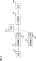
- Figure 3 shows a flow diagram 300 for handling a RAN failure according to an embodiment.
- a UE 301 corresponding to UE 201, a first RAN 302 corresponding to the first RAN 202, a CSF 303 corresponding to CSF 208 and a second RAN 304 corresponding to the second RAN 205 are involved in the flow.
- the UE establishes an RRC connection with the first RAN 302.
- the first RAN 302 (e.g. the old gNB 206) stores the UE's context in association with an ID of the old gNB and the PCI ID of the cell of the first RAN 302 used by the first UE 301 in the CSF 303.
- the failure can be e.g., a hardware failure, a software failure, a radio link failure, a reconfiguration failure, an integrity check failure, etc.
- the UE 301 requests RRC re-establishment from the second RAN 304 wherein it indicates the ("old") PCI ID and C-RNTI of its connection to the first RAN 302.
- the second RAN 304 is not able to retrieve the UE context from the first RAN 307, e.g. because the old gNB 206 is not available or because the new gNB 207 cannot identify the old gNB (or even the first RAN 207) by PCI ID + C-RNTI.
- the second RAN 304 (e.g. specifically the new gNB 207) sends a retrieve UE context request to the CSF 303.
- the retrieve UE context request it includes an ID of the new gNB and the "old" PCI ID and C-RNTI provided by the UE 301 in 308.
- the old PCI ID can be seen as an identification associated with the old gNB.
- the CSF 303 looks for a gNB (i.e. RAN node) which has a neighbour relation (e.g. is adjacent to or has an overlapping or adjacent coverage area with) the new gNB of the second RAN 202 (i.e. of the sender of the request of 310) and which provides a cell associated with the old PCI. Then, the CSF 303 extracts information which is stored under the PCI and which corresponds to the C-RNTI of the gNB found (i.e. the UE context).
- a gNB i.e. RAN node
- neighbour relation e.g. is adjacent to or has an overlapping or adjacent coverage area with
- the CSF 303 extracts information which is stored under the PCI and which corresponds to the C-RNTI of the gNB found (i.e. the UE context).
- the CSF 303 provides the UE context to the second RAN 304.
- the second RAN 304 (specifically the new gNB 307) then, in 313, re-establishes the RRC connection and allocates one or more DRBs (data radio bearers) for the UE 301.
- DRBs data radio bearers
- the old gNB and the new gNB may be indicated in 306 and 310, respectively, by means of a global RAN node ID (RAN ID).
- RAN ID RAN node ID
- the CSF 303 may use topology information of the first RAN 307 and the second RAN 304 like given in table 2 as an example.
- Table 2 Global RAN node ID Neighbor relation RAN ID#1 RAN ID#2 PCI#1, PCI#2, PCI#3 RAN ID#3 PCI#4, PCI#5, PCI#6 RAN ID#4 PCI#1, PCI#2, PCI#3 RAN ID#5 RAN ID#1 PCI#11, PCI#12, PCI#13 RAN ID#3 PCI#4, PCI#5, PCI#6 RAN ID#7 PCI#11, PCI#12, PCI#13
- the CSF 303 is shared between multiple PLMNs (Public Land Mobile Networks).
- PLMNs Public Land Mobile Networks
- the old gNB and the new gNB may includes the PLMN ID (PLMN identifier) during the context storage or retrieval process.
- PLMN ID PLMN identifier
- CSF can also be deployed in the non-public network (NPN) and can be also be shared between PLMNs and NPNs.
- the communication network there can be multiple CSFs 303 can be deployed e.g., in different locations.
- these CSFs are interconnected and exchange the stored information.
- the UE provides the location information that it attached old gNB, which new gNB forwards to the new CSF.
- the new CSF discoveries the old CSF using this location information and extracts the context.
- the multiple CSFs can be seen as a communication network component for UE context information which is implemented in a distributed manner (as multiple CSFs) or the request for mobile terminal context information of a RAN component can be seen to be received via another CSF.
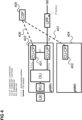
- Figure 4 illustrates the usage of a CSF in a C-RAN (Cloud RAN) architecture.
- the CU-CPs 401, 402 of the first gNB 403 and the second gNB 404 may be connected to the CSF 405 via a service-based interface 406, 407.
- a communication network component is provided as illustrated in figure 5 .
- Figure 5 shows a communication network component 500 according to an embodiment.
- the communication network component 500 (CSF in the above examples) includes a memory 501 configured to store, for each of a plurality base stations, for each of a plurality of connections provided by the base station, mobile terminal context information for the connection.
- the communication network component 500 includes an input interface 502 configured to receive, from a radio access network component, a request for mobile terminal context information for a connection previously provided by one of the base stations for a mobile terminal.
- the communication network component 500 further includes a determiner 503 configured to determine, among the mobile terminal context information stored, mobile terminal context information for the connection previously provided by the one of the base stations for the mobile terminal and an output interface 504 configured to send the mobile terminal context information for the connection previously provided by the one of the base stations for the mobile terminal to the radio access network component.
- a determiner 503 configured to determine, among the mobile terminal context information stored, mobile terminal context information for the connection previously provided by the one of the base stations for the mobile terminal and an output interface 504 configured to send the mobile terminal context information for the connection previously provided by the one of the base stations for the mobile terminal to the radio access network component.
- a centralized storage function is introduced for mobile terminal (e.g. UE) context to allow handling of the failure of a RAN, i.e. the UE context is maintained in a centralized storage in a communication system.
- figure 5 enables quick recovery of the UE context from a RAN to handle RAN failure scenarios. By managing and maintaing the UE context within the network, impact on the UE is avoided and high reliability can be achieved.
- the communication network component (which may also be seen as mobile terminal context information storage component) may be configured (e.g. its input interface) to receive the mobile terminal context information for the connections from the plurality of base stations and to store them upon reception.
- the communication network component for example carries out a method as illustrated in figure 6 .
- Figure 6 shows a flow diagram 600 illustrating a method for re-establishment of a communication connection.
- a request for mobile terminal context information for a connection previously provided by one of the base stations for a mobile terminal is received from a radio access network component.
- mobile terminal context information for the connection previously provided by the one of the base stations for the mobile terminal is determined among the mobile terminal context information stored.
- the mobile terminal context information for the connection previously provided by the one of the base stations for the mobile terminal is sent to the radio access network component.
- the components of the communication network component may for example be implemented by one or more circuits.
- a “circuit” may be understood as any kind of a logic implementing entity, which may be special purpose circuitry or a processor executing software stored in a memory, firmware, or any combination thereof.
- a “circuit” may be a hard-wired logic circuit or a programmable logic circuit such as a programmable processor, e.g. a microprocessor.
- a “circuit” may also be a processor executing software, e.g. any kind of computer program.
Landscapes
- Engineering & Computer Science (AREA)
- Computer Networks & Wireless Communication (AREA)
- Signal Processing (AREA)
- Mobile Radio Communication Systems (AREA)
Abstract
Description
- The present disclosure relates to communication network components and methods for re-establishment of a communication connection.
- In case of a failure of a radio access network, e.g. of a base station, providing a communication connection for a mobile terminal, it is typically desirable that the communication connection is quickly re-established. For quick re-establishment, the "new" base station, i.e. the base station which provides the re-established communication connection, needs mobile terminal context information such as a security context (e.g. encryption keys) and various other parameters whose reselection would delay the re-establishment (and would in fact rather mean that a new connection is established rather than the previous connection is re-established). However, it may not be easy or even possible for the new base station to acquire the mobile terminal context information.
- Accordingly, approaches which allow acquiring mobile terminal context information for re-establishment of communication connections are desirable.
- According to various embodiments, a communication network component is provided including a memory configured to store, for each of a plurality base stations, for each of a plurality of connections provided by the base station, mobile terminal context information for the connection, an input interface configured to receive, from a radio access network component, a request for mobile terminal context information for a connection previously provided by one of the base stations for a mobile terminal, a determiner configured to determine, among the mobile terminal context information stored, mobile terminal context information for the connection previously provided by the one of the base stations for the mobile terminal and an output interface configured to send the mobile terminal context information for the connection previously provided by the one of the base stations for the mobile terminal to the radio access network component.
- In the drawings, like reference characters generally refer to the same parts throughout the different views. The drawings are not necessarily to scale, emphasis instead generally being placed upon illustrating the principles of the invention. In the following description, various aspects are described with reference to the following drawings, in which:
- Figure 1
- shows a radio communication system.
- Figure 2
- illustrates a scenario where a UE (user equipment) is connected via a first RAN (radio access network) and a first UPF (user plane function) to a server.
- Figure 3
- shows a flow diagram for handling a RAN failure according to an embodiment.
- Figure 4
- illustrates the usage of a CSF (centralized storage function) in a C-RAN (Cloud RAN) architecture.
- Figure 5
- shows a communication network component according to an embodiment.
- Figure 6
- shows a flow diagram illustrating a method for re-establishment of a communication connection.
- The following detailed description refers to the accompanying drawings that show, by way of illustration, specific details and aspects of this disclosure in which the invention may be practiced. Other aspects may be utilized and structural, logical, and electrical changes may be made without departing from the scope of the invention. The various aspects of this disclosure are not necessarily mutually exclusive, as some aspects of this disclosure can be combined with one or more other aspects of this disclosure to form new aspects.
- Various examples corresponding to aspects of this disclosure are described below:
- Example 1 is a communication network component as described above.
- Example 2 is the communication network component of Example 1, wherein the base stations are base stations of a first radio access network and the radio access network component is a component of a second radio access network, wherein the first radio access network consists of other base stations than the second radio access network.
- Example 3 is the communication network component of Example 2, wherein the radio access network component is a base station of the second radio access network.
- Example 4 is the communication network component of any one of Examples 1 to 3, wherein the communication network component is configured to receive, from the radio access network component, an identification associated with the one of the base stations and an identification of a base station which is to re-establish the communication connection and to determine the mobile terminal context information for the connection previously provided by the one of the base stations for the mobile terminal by identifying, among the plurality of base stations, a base station which fits the identification associated with one of the base stations and is in the vicinity of the base station which is to re-establish the communication connection and by determining the mobile terminal context information stored for the identified base station as the mobile terminal context information for the connection previously provided.
- Example 5 is the communication network component of Examples 4, comprising identifying the base station which fits the identification of the one of the base stations and is in the vicinity of the base station which is to re-establish the communication connection by identifying a base station among the plurality of base stations which is closest to the base station which is to re-establish the communication connection among the base stations
- Example 6 is the communication network component of Example 5, configured to store topology information of a deployment of the plurality of base stations and/or of a radio access network to which the base station which is to re-establish the communication connection belongs and to identify the base station which fits the identification of the one of the base stations and is in the vicinity of the base station which is to re-establish the communication connection using the topology information.
- Example 7 is the communication network component of any one of Examples 1 to 6, wherein the connection is a radio resource control layer connection.
- Example 8 is the communication network component of any one of Examples 1 to 7, wherein the mobile terminal context information includes one or more of a network slice identifier of a network slice providing a communication service via the communication connection, an identifier of an access and mobility management function handling the communication connection, an identifier of an access point for communication between the one of the base stations and the access and mobility management function handling the communication connection, an identifier for each of one or more data radio bearers associated with the communication connection, an identifier of a centralized unit and a distributed unit of the one of the base stations, a security context of the communication connection, an identifier of the mobile terminal and transport layer address parameters of the communication connection.
- Example 9 is the communication network component of any one of Examples 1 to 8, wherein the memory is configured to store mobile terminal context information for connections provided by base stations provided by different public land mobile networks, wherein, for each public land mobile network, mobile terminal context information stored for a connection provided by the public land mobile network is stored in association with an identification of the public land mobile network.
- Example 10 is the communication network component of any one of Examples 1 to 9, wherein the input interface is configured to receive the request from the radio access network component via another communication network component for storing mobile terminal context information.
- Example 11 is a communication network comprising the communication network component of any one of Examples 1 to 10 and comprising the radio access network component, wherein the radio access network is configured to receive a request for re-establishment of the communication connection, determine whether it can acquire the mobile terminal context information from the one of the base stations; and, if it cannot acquire the mobile terminal context information from the one of the base stations, send the request for mobile terminal context information to the communication network component.
- Example 12 is the communication network of Example 11, further comprising the plurality of base stations, wherein each base station is configured to store, for each of a plurality of connections provided by the base station, mobile terminal context information for the connection in the communication network component.
- Example 13 is the communication network of Example 12, wherein each base station is configured to configure the mobile terminal context information for providing the connection, copy the mobile terminal context information to the communication network component and maintain the mobile terminal context information for providing the connection.
- Example 14 is a method for re-establishment of a communication connection as illustrated in
figure 6 . - It should be noted that one or more of the features of any of the examples above may be combined with any one of the other examples. In particular, the Examples described in context of the device are analogously valid for the method.
- According to further embodiments, a computer program and a computer readable medium including instructions, which, when executed by a computer, make the computer perform the method of any one of the above Examples are provided.
- In the following, various examples will be described in more detail.
-
Figure 1 shows aradio communication system 100, for example configured according to 5G (Fifth Generation) as specified by 3GPP (Third Generation Partnership Project), i.e. for example a 5GS. - The
radio communication system 100 includes a mobileradio terminal device 102 such as a UE (user equipment), a nano equipment (NE), and the like. The mobileradio terminal device 102, also referred to as subscriber terminal, forms the terminal side while the other components of theradio communication system 100 described in the following are part of the mobile radio communication network side, i.e. part of a mobile radio communication network (e.g. a Public Land Mobile Network PLMN). - Furthermore, the
radio communication system 100 includes aradio access network 103, which may include a plurality of radio access network nodes, i.e. base stations configured to provide radio access in accordance with a 5G (Fifth Generation) radio access technology (5G New Radio). It should be noted that theradio communication system 100 may also be configured in accordance with LTE (Long Term Evolution) or another mobile radio communication standard but 5G is herein used as an example. Each radioaccess network node 103 may provide a radio communication with the mobileradio terminal device 102 over an air interface. It should be noted that theradio access network 103 may include any number of radio access network nodes. - The
radio communication system 100 further includes a core network (CN, here 5GC) 108 including an Access and Mobility Management Function (AMF) 101 connected to the RAN 103 and a Unified Data Management (UDM) 104. Here and in the following examples, the UDM may further consist of the actual UE's subscription database, which is known as, for example, the UDR (Unified Data Repository). Thecore network 108 further includes an AUSF (Authentication Server Function) 109 and one or more PCFs (Policy Control Functions), in this example a first PCF 106 and a second PCF 107. - The
core network 108 further includes multiple Session Management Functions (SMFs), in this example a first Session Management Function (SMF) 110 and a second Session Management Function (SMF) 112 and multiple User Plane Functions (UPFs), in this example a first User Plane Function (UPF) 111 a second User Plane Function (UPF) 113. TheSMFs - The
core network 108 further includes an application function (AF) 105. The AF 105 is shown to be directly connected to theSMFs AF 105 is maintained by a third party (i.e. a party other than the operation of the mobileradio communication system 100. - The AF 105 enables an application to request the
5G system 100 to support specific QoS (Quality of Service) policies for a UE 102 that establishes a PDU session to provide a communication service for that application. - It may occur that the
RAN 103 fails and thus, a communication service, e.g. a connection to an application server, is interrupted. In such a case, it is desirable that a replacement connection is quickly built up. This is in particular the case in case of traffic which requires (or should provide) high reliability and/or low latency, such as URLLC (Ultra reliable low latency communications) traffic. It should be noted that this may also be desirable in case that there is not a total failure of the RAN 103 but other abnormal conditions like a large loss of quality of service, e.g. latency or throughput. Therefore, a second RAN may be used to establish a replacement connection. -
Figure 2 illustrates a scenario where a UE 201 is connected via a first RAN 202 and a first UPF 203 to a server 204 (here an edge server, denoted as E1). - It is assumed that in case of a failure (or other abnormal condition) of the first RAN 202, a second RAN 205 is available which may be used by the UE 201 to connect to the
server 204. - When using the
first RAN 202 to connect to theserver 204, theUE 201 performs radio communication with a first base station (gNodeB or gNB in 5G) 206, denoted as "old gNB" (since it is used before the failure) of thefirst RAN 202. Specifically, theUE 201 uses a radio cell (denoted as "old" radio cell) provided by theold gNB 206. When using thesecond RAN 205 to connect to theserver 204, theUE 201 performs radio communication with asecond base station 207, denoted as "new gNB" or "target gNB" (since it is used after the failure) of thesecond RAN 205. Specifically, theUE 201 uses a radio cell (denoted as "new" radio cell) provided by thenew gNB 207. - To achieve a quick reestablishment of the communication service, the
UE 201 requests RRC (Radio Resource Control) re-establishment in case of a failure of thefirst RAN 202 to thenew gNB 207. - The
UE 201 provides the PCI (physical cell identifier) of the old radio cell in the RRC re-establishment request message to thenew gNB 207. TheUE 201 also provides its C-RNTI (cell radio network temporary identity). Since in the present scenario the UE context is not locally available, thenew gNB 207 then tries to find theold gNB 206 for requesting the UE context. For this, thenew gNB 207 checks the NCRT (neighbour cell relation table), which maps PCI to NCI, for PCI and NCI (new radio cell ID) to determine theold gNB 206 - If it finds the
old gNB 206 in this manner, thenew gNB 207 fetches the UE context fromold gNB 206. If it does not find theold gNB 206, thenew gNB 207 sends a RRC reject message to theUE 201 in response to the RRC connect re-establishment request. - This means that, if the
new gNB 207 cannot find the old gNB 206 (i.e. cannot contact theold gNB 206 to obtain the UE context of the connection which has failed), theUE 201 needs to request the establishment of a new RRC connection from thenew gNB 207. - Once the
UE 201 sends request for the establishment of the new RRC connection, thenew gNB 207 communicates with anAMF 101 to establish a new UE context in thenew gNB 207. - So, in case of failure (and thus unavailability) of the old gNB (e.g. hardware failure or software failure), the
new gNB 207 tries to find theold gNB 206 based on the NCRT/NRT (Neighbour Relation Table) information but, due to the old gNB's unavailability, thenew gNB 206 cannot find theold gNB 206 and rejects the UE's request. - Furthermore, it may not be easy for the
new gNB 207 to find the old gNB 206 (even if theold gNB 207 has not failed itself). This is because the PCI carries a certain information to identify theold gNB 206 but can have only one of 1008 values in NR (new radio) and is not globally unique and thesecond RAN 205 may not have NRT information of thefirst RAN 204. - The NR Cell Identity (NCI) has a total size of 36 bits and is unique. The NR Cell Global Identifier (NCGI) is used to identify NR cells globally. The NR Cell Identity is broadcast within SIB#1 (system information block number 1). However, in NSA (non-standalone) deployments (in EN-DC configuration) a NR base station does not broadcast NCI in the
SIB# 1 information which results in UE not being able to decode and report the CGI (cell global identity) information. - According to various embodiments, to simplify the RAN failure handling the UE context of a RAN is stored in a centralized function, allowing the service interruption for the UE in case of a RAN failure to be reduced since a RRC re-establishment rather than establishment of a new RRC connection is made possible (even if the old gNB is not available or cannot be identified by the new gNB). For this, functions and/or parameters may be added to the Xn interface with corresponding logic inside the RAN nodes (base stations).
- Specifically, according to various embodiments, every time a RAN (e.g. first RAN 202) accepts a UE (i.e. there is UE Initial Access) and/or a PDU Session is established, the
RAN 202 creates or updates the RAN's UE context stored in a UEcontext storage component 208, i.e. a centralized storage function (CSF). - The
CSF 208 supports handling a failure of thefirst RAN 202 by exposing a (e.g. standardized) interface, which is used by thefirst RAN 202 to update or retire the UE context and may be consulted by thenew gNB 207, for example, in case of a failure of thefirst RAN 202. - The
CSF 208 can be part of gNB-CU (centralized unit). In that case, all associated gNB-DUs (distributed units) store the context in theCSF 208. Alternatively, theCSF 208 can be a standalone function. In that case, all gNB-CUs and/or gNB-DUs store the context in theCSF 208. - Table 1 shows exemplary elements of a UE context which may be stored in the
CSF 208.Table 1 Context type Description N2 details NG-AP identifiers, AMF details, etc. DRB details Information about the active DRBs (identifiers) F1 interface and E1 interface details UE-associated identifiers of the interfaces Serving node details Identifier of gNB-CU (gNB-CU-CP and gNB-CU-UP) and gNB-DU PCI Serving PCI information S-NSSAI(s) Slice information Security context Security details e.g., keys for encryption UE identifier Unique UE identifier GUTI, GUMMEI, etc. Transport layer details transport layer address parameter e.g., for transport bearer connections -
Figure 3 shows a flow diagram 300 for handling a RAN failure according to an embodiment. - A
UE 301 corresponding toUE 201, afirst RAN 302 corresponding to thefirst RAN 202, aCSF 303 corresponding toCSF 208 and asecond RAN 304 corresponding to thesecond RAN 205 are involved in the flow. - In 305, the UE establishes an RRC connection with the
first RAN 302. - In 306, the first RAN 302 (e.g. the old gNB 206) stores the UE's context in association with an ID of the old gNB and the PCI ID of the cell of the
first RAN 302 used by thefirst UE 301 in theCSF 303. - It is assumed that in 307 there is a failure of the
first RAN 302. The failure can be e.g., a hardware failure, a software failure, a radio link failure, a reconfiguration failure, an integrity check failure, etc. - To avoid (long) service interruption the
UE 301, in 308, requests RRC re-establishment from thesecond RAN 304 wherein it indicates the ("old") PCI ID and C-RNTI of its connection to thefirst RAN 302. - It is assumed that the
second RAN 304 is not able to retrieve the UE context from thefirst RAN 307, e.g. because theold gNB 206 is not available or because thenew gNB 207 cannot identify the old gNB (or even the first RAN 207) by PCI ID + C-RNTI. - Therefore, in 310, the second RAN 304 (e.g. specifically the new gNB 207) sends a retrieve UE context request to the
CSF 303. In the retrieve UE context request it includes an ID of the new gNB and the "old" PCI ID and C-RNTI provided by theUE 301 in 308. The old PCI ID can be seen as an identification associated with the old gNB. - In 311, the
CSF 303 looks for a gNB (i.e. RAN node) which has a neighbour relation (e.g. is adjacent to or has an overlapping or adjacent coverage area with) the new gNB of the second RAN 202 (i.e. of the sender of the request of 310) and which provides a cell associated with the old PCI. Then, theCSF 303 extracts information which is stored under the PCI and which corresponds to the C-RNTI of the gNB found (i.e. the UE context). - In 312, the
CSF 303 provides the UE context to thesecond RAN 304. - The second RAN 304 (specifically the new gNB 307) then, in 313, re-establishes the RRC connection and allocates one or more DRBs (data radio bearers) for the
UE 301. - The old gNB and the new gNB may be indicated in 306 and 310, respectively, by means of a global RAN node ID (RAN ID).
- For 311, the
CSF 303 may use topology information of thefirst RAN 307 and thesecond RAN 304 like given in table 2 as an example.Table 2 Global RAN node ID Neighbor relation RAN ID# 1RAN ID# 2PCI# 1,PCI# 2, PCI#3RAN ID#3 PCI#4, PCI#5, PCI#6 RAN ID#4 PCI# 1,PCI# 2, PCI#3RAN ID#5 RAN ID# 1PCI#11, PCI#12, PCI#13 RAN ID#3 PCI#4, PCI#5, PCI#6 RAN ID#7 PCI#11, PCI#12, PCI#13 - It should be noted note that it is also possible that the
CSF 303 is shared between multiple PLMNs (Public Land Mobile Networks). In the case, the old gNB and the new gNB may includes the PLMN ID (PLMN identifier) during the context storage or retrieval process. Furthermore, CSF can also be deployed in the non-public network (NPN) and can be also be shared between PLMNs and NPNs. - In addition, it is also possible that in the communication network, there can be
multiple CSFs 303 can be deployed e.g., in different locations. In this case, these CSFs are interconnected and exchange the stored information. For example, the UE provides the location information that it attached old gNB, which new gNB forwards to the new CSF. The new CSF discoveries the old CSF using this location information and extracts the context. In that case the multiple CSFs can be seen as a communication network component for UE context information which is implemented in a distributed manner (as multiple CSFs) or the request for mobile terminal context information of a RAN component can be seen to be received via another CSF. -
Figure 4 illustrates the usage of a CSF in a C-RAN (Cloud RAN) architecture. - In that case, the CU-
CPs first gNB 403 and thesecond gNB 404 may be connected to theCSF 405 via a service-basedinterface - In summary, according to various embodiments, a communication network component is provided as illustrated in
figure 5 . -
Figure 5 shows acommunication network component 500 according to an embodiment. - The communication network component 500 (CSF in the above examples) includes a
memory 501 configured to store, for each of a plurality base stations, for each of a plurality of connections provided by the base station, mobile terminal context information for the connection. - Further, the
communication network component 500 includes aninput interface 502 configured to receive, from a radio access network component, a request for mobile terminal context information for a connection previously provided by one of the base stations for a mobile terminal. - The
communication network component 500 further includes adeterminer 503 configured to determine, among the mobile terminal context information stored, mobile terminal context information for the connection previously provided by the one of the base stations for the mobile terminal and anoutput interface 504 configured to send the mobile terminal context information for the connection previously provided by the one of the base stations for the mobile terminal to the radio access network component. - According to various embodiments, in other words, a centralized storage function is introduced for mobile terminal (e.g. UE) context to allow handling of the failure of a RAN, i.e. the UE context is maintained in a centralized storage in a communication system.
- The approach of
figure 5 enables quick recovery of the UE context from a RAN to handle RAN failure scenarios. By managing and maintaing the UE context within the network, impact on the UE is avoided and high reliability can be achieved. - The communication network component (which may also be seen as mobile terminal context information storage component) may be configured (e.g. its input interface) to receive the mobile terminal context information for the connections from the plurality of base stations and to store them upon reception.
- The communication network component for example carries out a method as illustrated in
figure 6 . -
Figure 6 shows a flow diagram 600 illustrating a method for re-establishment of a communication connection. - In 601, for each of a plurality base stations, for each of a plurality of connections provided by the base station, mobile terminal context information for the connection is stored.
- In 602, a request for mobile terminal context information for a connection previously provided by one of the base stations for a mobile terminal is received from a radio access network component.
- In 603 mobile terminal context information for the connection previously provided by the one of the base stations for the mobile terminal is determined among the mobile terminal context information stored.
- In 604, the mobile terminal context information for the connection previously provided by the one of the base stations for the mobile terminal is sent to the radio access network component.
- The components of the communication network component (e.g. the determiner and the interfaces) may for example be implemented by one or more circuits. A "circuit" may be understood as any kind of a logic implementing entity, which may be special purpose circuitry or a processor executing software stored in a memory, firmware, or any combination thereof. Thus a "circuit" may be a hard-wired logic circuit or a programmable logic circuit such as a programmable processor, e.g. a microprocessor. A "circuit" may also be a processor executing software, e.g. any kind of computer program.
- Any other kind of implementation of the respective functions described above may also be understood as a "circuit".
- While specific aspects have been described, it should be understood by those skilled in the art that various changes in form and detail may be made therein without departing from the spirit and scope of the aspects of this disclosure as defined by the appended claims. The scope is thus indicated by the appended claims and all changes which come within the meaning and range of equivalency of the claims are therefore intended to be embraced.
Claims (14)
- A communication network component comprisingA memory configured to store, for each of a plurality base stations, for each of a plurality of connections provided by the base station, mobile terminal context information for the connection;An input interface configured to receive, from a radio access network component, a request for mobile terminal context information for a connection previously provided by one of the base stations for a mobile terminal;A determiner configured to determine, among the mobile terminal context information stored, mobile terminal context information for the connection previously provided by the one of the base stations for the mobile terminal; and An output interface configured to send the mobile terminal context information for the connection previously provided by the one of the base stations for the mobile terminal to the radio access network component.
- The communication network component of claim 1, wherein the base stations are base stations of a first radio access network and the radio access network component is a component of a second radio access network, wherein the first radio access network consists of other base stations than the second radio access network.
- The communication network component of claim 2, wherein the radio access network component is a base station of the second radio access network.
- The communication network component of any one of claims 1 to 3, wherein the communication network component is configured to receive, from the radio access network component, an identification associated with the one of the base stations and an identification of a base station which is to re-establish the communication connection and to determine the mobile terminal context information for the connection previously provided by the one of the base stations for the mobile terminal by identifying, among the plurality of base stations, a base station which fits the identification associated with one of the base stations and is in the vicinity of the base station which is to re-establish the communication connection and by determining the mobile terminal context information stored for the identified base station as the mobile terminal context information for the connection previously provided.
- The communication network component of claims 4, comprising identifying the base station which fits the identification of the one of the base stations and is in the vicinity of the base station which is to re-establish the communication connection by identifying a base station among the plurality of base stations which is closest to the base station which is to re-establish the communication connection among the base stations
- The communication network component of claim 5, configured to store topology information of a deployment of the plurality of base stations and/or of a radio access network to which the base station which is to re-establish the communication connection belongs and to identify the base station which fits the identification of the one of the base stations and is in the vicinity of the base station which is to re-establish the communication connection using the topology information.
- The communication network component of any one of claims 1 to 6, wherein the connection is a radio resource control layer connection.
- The communication network component of any one of claims 1 to 7, wherein the mobile terminal context information includes one or more of a network slice identifier of a network slice providing a communication service via the communication connection;an identifier of an access and mobility management function handling the communication connection;an identifier of an access point for communication between the one of the base stations and the access and mobility management function handling the communication connection;an identifier for each of one or more data radio bearers associated with the communication connection;an identifier of a centralized unit and a distributed unit of the one of the base stations;a security context of the communication connection;an identifier of the mobile terminal; andtransport layer address parameters of the communication connection.
- The communication network component of any one of claims 1 to 8, wherein the memory is configured to store mobile terminal context information for connections provided by base stations provided by different public land mobile networks, wherein, for each public land mobile network, mobile terminal context information stored for a connection provided by the public land mobile network is stored in association with an identification of the public land mobile network.
- The communication network component of any one of claims 1 to 9, wherein the input interface is configured to receive the request from the radio access network component via another communication network component for storing mobile terminal context information.
- A communication network comprising the communication network component of any one of claims 1 to 10 and comprising the radio access network component, wherein the radio access network is configured to receive a request for re-establishment of the communication connection, determine whether it can acquire the mobile terminal context information from the one of the base stations; and, if it cannot acquire the mobile terminal context information from the one of the base stations, send the request for mobile terminal context information to the communication network component.
- The communication network of claim 11, further comprising the plurality of base stations, wherein each base station is configured to store, for each of a plurality of connections provided by the base station, mobile terminal context information for the connection in the communication network component.
- The communication network of claim 12, wherein each base station is configured to configure the mobile terminal context information for providing the connection, copy the mobile terminal context information to the communication network component and maintain the mobile terminal context information for providing the connection.
- A method for re-establishment of a communication connection, comprising:storing, for each of a plurality base stations, for each of a plurality of connections provided by the base station, mobile terminal context information for the connection;receiving, from a radio access network component, a request for mobile terminal context information for a connection previously provided by one of the base stations for a mobile terminal;determining, among the mobile terminal context information stored, mobile terminal context information for the connection previously provided by the one of the base stations for the mobile terminal; andsending the mobile terminal context information for the connection previously provided by the one of the base stations for the mobile terminal to the radio access network component.
Priority Applications (3)
| Application Number | Priority Date | Filing Date | Title |
|---|---|---|---|
| EP22185934.1A EP4311305A1 (en) | 2022-07-20 | 2022-07-20 | Communication network component and method for re-establishment of a communication connection |
| JP2023566551A JP7693831B2 (en) | 2022-07-20 | 2023-05-11 | COMMUNICATION NETWORK COMPONENTS AND METHOD FOR RE-ESTABLISHING A COMMUNICATION CONNECTION - Patent application |
| PCT/EP2023/062637 WO2024017519A1 (en) | 2022-07-20 | 2023-05-11 | Communication network component and method for re-establishment of a communication connection |
Applications Claiming Priority (1)
| Application Number | Priority Date | Filing Date | Title |
|---|---|---|---|
| EP22185934.1A EP4311305A1 (en) | 2022-07-20 | 2022-07-20 | Communication network component and method for re-establishment of a communication connection |
Publications (1)
| Publication Number | Publication Date |
|---|---|
| EP4311305A1 true EP4311305A1 (en) | 2024-01-24 |
Family
ID=82846193
Family Applications (1)
| Application Number | Title | Priority Date | Filing Date |
|---|---|---|---|
| EP22185934.1A Withdrawn EP4311305A1 (en) | 2022-07-20 | 2022-07-20 | Communication network component and method for re-establishment of a communication connection |
Country Status (3)
| Country | Link |
|---|---|
| EP (1) | EP4311305A1 (en) |
| JP (1) | JP7693831B2 (en) |
| WO (1) | WO2024017519A1 (en) |
Citations (4)
| Publication number | Priority date | Publication date | Assignee | Title |
|---|---|---|---|---|
| CN108024296A (en) * | 2016-11-04 | 2018-05-11 | 华为技术有限公司 | Method, system and the mobile management network element of handover network |
| US20190075497A1 (en) * | 2016-05-04 | 2019-03-07 | Huawei Technologies Co., Ltd. | User equipment handover method and device |
| US20210258766A1 (en) * | 2020-02-14 | 2021-08-19 | Cisco Technology, Inc. | Techniques to facilitate mobility management entity (mme) identification for user equipment context transfer |
| WO2022066071A1 (en) * | 2020-09-22 | 2022-03-31 | Telefonaktiebolaget Lm Ericsson (Publ) | Rrc re-establishment |
-
2022
- 2022-07-20 EP EP22185934.1A patent/EP4311305A1/en not_active Withdrawn
-
2023
- 2023-05-11 WO PCT/EP2023/062637 patent/WO2024017519A1/en not_active Ceased
- 2023-05-11 JP JP2023566551A patent/JP7693831B2/en active Active
Patent Citations (4)
| Publication number | Priority date | Publication date | Assignee | Title |
|---|---|---|---|---|
| US20190075497A1 (en) * | 2016-05-04 | 2019-03-07 | Huawei Technologies Co., Ltd. | User equipment handover method and device |
| CN108024296A (en) * | 2016-11-04 | 2018-05-11 | 华为技术有限公司 | Method, system and the mobile management network element of handover network |
| US20210258766A1 (en) * | 2020-02-14 | 2021-08-19 | Cisco Technology, Inc. | Techniques to facilitate mobility management entity (mme) identification for user equipment context transfer |
| WO2022066071A1 (en) * | 2020-09-22 | 2022-03-31 | Telefonaktiebolaget Lm Ericsson (Publ) | Rrc re-establishment |
Also Published As
| Publication number | Publication date |
|---|---|
| WO2024017519A1 (en) | 2024-01-25 |
| JP7693831B2 (en) | 2025-06-17 |
| JP2024530096A (en) | 2024-08-16 |
Similar Documents
| Publication | Publication Date | Title |
|---|---|---|
| US12446082B2 (en) | Method and apparatus for identifying user in radio access network communication system | |
| US11665668B2 (en) | Offset of international mobile subscriber identity | |
| US11963133B2 (en) | Core paging handling | |
| US10455489B2 (en) | Method for supporting PDN GW selection | |
| US12309592B2 (en) | Communication terminal, network device, communication method, and non-transitory computer readable medium | |
| CN111801961B (en) | A method and device for determining SSC mode | |
| CN114915614B (en) | Method and device for recovering IMS service | |
| KR20190018002A (en) | Method and apparatus for performing cell-specific procedures for network slice-based NR in a wireless communication system | |
| US20200267780A1 (en) | Handling QoS Flow Description and EPS Bearer Operation Errors in 4G 5G Systems | |
| CN110267362B (en) | Method and user equipment for maintaining maximum bearer number | |
| TWI792590B (en) | Method for pdu session establishment accept handling and user equipment thereof | |
| CN114980241B (en) | User equipment routing policy rule matching method and related user equipment | |
| US11399330B2 (en) | Routing selection method, apparatus, device and system, and storage medium | |
| CN113796156B (en) | Communication network components and methods for processing service requests | |
| CN106304246A (en) | A kind of cut-in method and corresponding access node, terminal and communication network | |
| CN112449404B (en) | Method and equipment for changing network access type of user terminal | |
| EP3979699B1 (en) | Data processing method and apparatus in dual connectivity re-establishment | |
| US12604247B2 (en) | Method, apparatus and computer program for indicating that a source access node connected to the first public land mobile network and a target access node connected to the second public land mobile network area same access node | |
| CN118355694A (en) | Method for releasing slice resources | |
| US20240306045A1 (en) | Method for session update after session management function failure and reselection | |
| EP4311305A1 (en) | Communication network component and method for re-establishment of a communication connection | |
| EP4718738A1 (en) | Device and method for providing communication between two mobile terminals | |
| EP4465679A1 (en) | Communication method and apparatus | |
| WO2022151030A1 (en) | Method and apparatus for automatic configuration of ng control plane interface |
Legal Events
| Date | Code | Title | Description |
|---|---|---|---|
| PUAI | Public reference made under article 153(3) epc to a published international application that has entered the european phase |
Free format text: ORIGINAL CODE: 0009012 |
|
| STAA | Information on the status of an ep patent application or granted ep patent |
Free format text: STATUS: REQUEST FOR EXAMINATION WAS MADE |
|
| 17P | Request for examination filed |
Effective date: 20230720 |
|
| AK | Designated contracting states |
Kind code of ref document: A1 Designated state(s): AL AT BE BG CH CY CZ DE DK EE ES FI FR GB GR HR HU IE IS IT LI LT LU LV MC MK MT NL NO PL PT RO RS SE SI SK SM TR |
|
| P01 | Opt-out of the competence of the unified patent court (upc) registered |
Effective date: 20240513 |
|
| STAA | Information on the status of an ep patent application or granted ep patent |
Free format text: STATUS: EXAMINATION IS IN PROGRESS |
|
| 17Q | First examination report despatched |
Effective date: 20251124 |
|
| STAA | Information on the status of an ep patent application or granted ep patent |
Free format text: STATUS: THE APPLICATION HAS BEEN WITHDRAWN |
|
| 18W | Application withdrawn |
Effective date: 20260323 |