EP4311215A1 - Image processing apparatus, program, and image processing method - Google Patents
Image processing apparatus, program, and image processing method Download PDFInfo
- Publication number
- EP4311215A1 EP4311215A1 EP23163440.3A EP23163440A EP4311215A1 EP 4311215 A1 EP4311215 A1 EP 4311215A1 EP 23163440 A EP23163440 A EP 23163440A EP 4311215 A1 EP4311215 A1 EP 4311215A1
- Authority
- EP
- European Patent Office
- Prior art keywords
- document
- imaging
- image
- documents
- image processing
- Prior art date
- Legal status (The legal status is an assumption and is not a legal conclusion. Google has not performed a legal analysis and makes no representation as to the accuracy of the status listed.)
- Granted
Links
Images



Classifications
-
- H—ELECTRICITY
- H04—ELECTRIC COMMUNICATION TECHNIQUE
- H04N—PICTORIAL COMMUNICATION, e.g. TELEVISION
- H04N1/00—Scanning, transmission or reproduction of documents or the like, e.g. facsimile transmission; Details thereof
- H04N1/00567—Handling of original or reproduction media, e.g. cutting, separating, stacking
- H04N1/0066—Aligning or positioning related to handling
-
- H—ELECTRICITY
- H04—ELECTRIC COMMUNICATION TECHNIQUE
- H04N—PICTORIAL COMMUNICATION, e.g. TELEVISION
- H04N23/00—Cameras or camera modules comprising electronic image sensors; Control thereof
- H04N23/60—Control of cameras or camera modules
- H04N23/64—Computer-aided capture of images, e.g. transfer from script file into camera, check of taken image quality, advice or proposal for image composition or decision on when to take image
-
- H—ELECTRICITY
- H04—ELECTRIC COMMUNICATION TECHNIQUE
- H04N—PICTORIAL COMMUNICATION, e.g. TELEVISION
- H04N1/00—Scanning, transmission or reproduction of documents or the like, e.g. facsimile transmission; Details thereof
- H04N1/04—Scanning arrangements, i.e. arrangements for the displacement of active reading or reproducing elements relative to the original or reproducing medium, or vice versa
- H04N1/203—Simultaneous scanning of two or more separate pictures, e.g. two sides of the same sheet
- H04N1/2036—Simultaneous scanning of two or more separate pictures, e.g. two sides of the same sheet of a plurality of pictures corresponding to a single side of a plurality of media
- H04N1/2038—Simultaneous scanning of two or more separate pictures, e.g. two sides of the same sheet of a plurality of pictures corresponding to a single side of a plurality of media lying in the same plane
-
- H—ELECTRICITY
- H04—ELECTRIC COMMUNICATION TECHNIQUE
- H04N—PICTORIAL COMMUNICATION, e.g. TELEVISION
- H04N1/00—Scanning, transmission or reproduction of documents or the like, e.g. facsimile transmission; Details thereof
- H04N1/0035—User-machine interface; Control console
- H04N1/00405—Output means
- H04N1/00408—Display of information to the user, e.g. menus
- H04N1/0044—Display of information to the user, e.g. menus for image preview or review, e.g. to help the user position a sheet
-
- H—ELECTRICITY
- H04—ELECTRIC COMMUNICATION TECHNIQUE
- H04N—PICTORIAL COMMUNICATION, e.g. TELEVISION
- H04N1/00—Scanning, transmission or reproduction of documents or the like, e.g. facsimile transmission; Details thereof
- H04N1/0035—User-machine interface; Control console
- H04N1/00405—Output means
- H04N1/00408—Display of information to the user, e.g. menus
- H04N1/0044—Display of information to the user, e.g. menus for image preview or review, e.g. to help the user position a sheet
- H04N1/00442—Simultaneous viewing of a plurality of images, e.g. using a mosaic display arrangement of thumbnails
-
- H—ELECTRICITY
- H04—ELECTRIC COMMUNICATION TECHNIQUE
- H04N—PICTORIAL COMMUNICATION, e.g. TELEVISION
- H04N1/00—Scanning, transmission or reproduction of documents or the like, e.g. facsimile transmission; Details thereof
- H04N1/0035—User-machine interface; Control console
- H04N1/00405—Output means
- H04N1/0049—Output means providing a visual indication to the user, e.g. using a lamp
-
- H—ELECTRICITY
- H04—ELECTRIC COMMUNICATION TECHNIQUE
- H04N—PICTORIAL COMMUNICATION, e.g. TELEVISION
- H04N1/00—Scanning, transmission or reproduction of documents or the like, e.g. facsimile transmission; Details thereof
- H04N1/00567—Handling of original or reproduction media, e.g. cutting, separating, stacking
-
- H—ELECTRICITY
- H04—ELECTRIC COMMUNICATION TECHNIQUE
- H04N—PICTORIAL COMMUNICATION, e.g. TELEVISION
- H04N1/00—Scanning, transmission or reproduction of documents or the like, e.g. facsimile transmission; Details thereof
- H04N1/00681—Detecting the presence, position or size of a sheet or correcting its position before scanning
- H04N1/00684—Object of the detection
- H04N1/00702—Position
-
- H—ELECTRICITY
- H04—ELECTRIC COMMUNICATION TECHNIQUE
- H04N—PICTORIAL COMMUNICATION, e.g. TELEVISION
- H04N1/00—Scanning, transmission or reproduction of documents or the like, e.g. facsimile transmission; Details thereof
- H04N1/00681—Detecting the presence, position or size of a sheet or correcting its position before scanning
- H04N1/00785—Correcting the position of a sheet before scanning
- H04N1/0079—Correcting the position of a sheet before scanning using guide or holder
-
- H—ELECTRICITY
- H04—ELECTRIC COMMUNICATION TECHNIQUE
- H04N—PICTORIAL COMMUNICATION, e.g. TELEVISION
- H04N1/00—Scanning, transmission or reproduction of documents or the like, e.g. facsimile transmission; Details thereof
- H04N1/024—Details of scanning heads ; Means for illuminating the original
- H04N1/028—Details of scanning heads ; Means for illuminating the original for picture information pick-up
-
- H—ELECTRICITY
- H04—ELECTRIC COMMUNICATION TECHNIQUE
- H04N—PICTORIAL COMMUNICATION, e.g. TELEVISION
- H04N1/00—Scanning, transmission or reproduction of documents or the like, e.g. facsimile transmission; Details thereof
- H04N1/04—Scanning arrangements, i.e. arrangements for the displacement of active reading or reproducing elements relative to the original or reproducing medium, or vice versa
- H04N1/19—Scanning arrangements, i.e. arrangements for the displacement of active reading or reproducing elements relative to the original or reproducing medium, or vice versa using multi-element arrays
- H04N1/195—Scanning arrangements, i.e. arrangements for the displacement of active reading or reproducing elements relative to the original or reproducing medium, or vice versa using multi-element arrays the array comprising a two-dimensional [2D] array
- H04N1/19594—Scanning arrangements, i.e. arrangements for the displacement of active reading or reproducing elements relative to the original or reproducing medium, or vice versa using multi-element arrays the array comprising a two-dimensional [2D] array using a television camera or a still video camera
-
- H—ELECTRICITY
- H04—ELECTRIC COMMUNICATION TECHNIQUE
- H04N—PICTORIAL COMMUNICATION, e.g. TELEVISION
- H04N23/00—Cameras or camera modules comprising electronic image sensors; Control thereof
- H04N23/60—Control of cameras or camera modules
- H04N23/63—Control of cameras or camera modules by using electronic viewfinders
- H04N23/633—Control of cameras or camera modules by using electronic viewfinders for displaying additional information relating to control or operation of the camera
Definitions
- the present invention relates to an image processing apparatus, a program, and an image processing method.
- JP6737341B describes an image forming apparatus in which, even for a plurality of small-size documents, an image of a front side and an image of a back side of each document can be superimposed and formed on the image positions of the front and back sides which have been aligned on the front and back of one sheet of recording paper.
- an imaging unit such as a camera may be provided, and an image may be acquired by imaging a document by using the imaging unit.
- a plurality of related documents such as the front side and the back side of a business card are imaged one by one in order, and the acquired images of the plurality of documents are associated with each other, thereby managing the images of the plurality of related documents as a group.
- An object of the present invention is to provide an image processing apparatus, a program, and an image processing method capable of allowing a user to know a position where the document of each set is placed, in a case where there are a plurality of sets each consisting of a plurality of documents and a plurality of sheets of documents including one sheet of document of each set are simultaneously imaged.
- an image processing apparatus including a processor configured to: display, in a case where there are a plurality of sets each consisting of a plurality of documents, and a plurality of sheets of documents including at least one sheet of a document of each of all or part of the plurality of sets are simultaneously imaged by an imaging unit that images a document, guidance information for guiding a placement position of the document of each set to be superimposed on an image imaged by the imaging unit and representing a current state, on a display unit, in second and subsequent imaging, by using information pertaining to documents acquired in past imaging.
- the image processing apparatus in which the guidance information may be images of the documents acquired in the past imaging.
- the image processing apparatus in which the guidance information may be images in a state in which the images of the documents acquired in the past imaging are made transparent at a preset transparency.
- the image processing apparatus in which the guidance information may be an image of a frame representing an outline of each document acquired in the past imaging.
- the image processing apparatus in which the guidance information may include an image indicating at least one of up, down, right, or left directions of each document.
- the image processing apparatus according to any one of the first to fifth aspects, in which the processor may be configured to change a transparency in displaying the guidance information in accordance with a user operation.
- the image processing apparatus according to any one of the first to sixth aspects, in which the processor may be configured to switch between a display state and a hidden state of the guidance information in accordance with a user operation.
- the image processing apparatus according to any one of the first to seventh aspects, in which the plurality of documents included in each set may be a front-side document and a back-side document of one medium.
- a program causing a computer to execute a process including: displaying, in a case where there are a plurality of sets each consisting of a plurality of documents, and a plurality of sheets of documents including at least one sheet of a document of each of all or part of the plurality of sets are simultaneously imaged by an imaging unit that images a document, guidance information for guiding a placement position of the document of each set to be superimposed on an image imaged by the imaging unit and representing a current state, on a display unit, in second and subsequent imaging, by using information pertaining to documents acquired in past imaging.
- an image processing method including: displaying, in a case where there are a plurality of sets each consisting of a plurality of documents, and a plurality of sheets of documents including at least one sheet of a document of each of all or part of the plurality of sets are simultaneously imaged by an imaging unit that images a document, guidance information for guiding a placement position of the document of each set to be superimposed on an image imaged by the imaging unit and representing a current state, on a display unit, in second and subsequent imaging, by using information pertaining to documents acquired in past imaging.
- the image processing apparatus of the first aspect in a case where there are a plurality of sets each consisting of a plurality of related documents, and a plurality of sheets of documents including one sheet of a document of each set are simultaneously imaged, a user is allowed to know a position where the document of each set is placed.
- the image processing apparatus of the second aspect it is possible to guide the placement position while checking the content of the image captured in the past.
- the image processing apparatus of the third aspect even in a case where the guidance information and the image of the document to be newly imaged overlap each other in the moving image representing the current state, the contents of both images can be visually recognized.
- the content of the guidance information can be simply displayed with only a frame line.
- related documents can be associated with each other by being aligned vertically and horizontally.
- a density at which the guidance information is displayed can be adjusted according to the preference of the user.
- the image processing apparatus of the seventh aspect it is possible to facilitate checking of an image of a document to be newly captured, as compared with a case where the guidance information is always displayed.
- the image of the front-side document and the image of the back-side document can be associated with each other.
- a user in a case where there are a plurality of sets each consisting of a plurality of related documents, and a plurality of sheets of documents including one sheet of a document of each set are simultaneously imaged, a user is allowed to know a position where the document of each set is placed.
- the image processing method of the tenth aspect in a case where there are a plurality of sets each consisting of a plurality of related documents, and a plurality of sheets of documents including one sheet of a document of each set are simultaneously imaged, a user is allowed to know a position where the document of each set is placed.
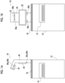
- FIGs. 1A and 1B are views showing an external appearance of an image forming apparatus 10 as an example of an image processing apparatus according to an exemplary embodiment of the present invention, where Fig. 1A is a side view of the image forming apparatus 10 and Fig. 1B is a front view of the image forming apparatus 10.
- the image forming apparatus 10 is an apparatus installed in an office such as a multifunction machine.
- the image forming apparatus 10 includes an apparatus main body 12, a discharge tray 14 as a medium discharge unit, a placement unit 16, an imaging device 18, an irradiation device 20 including four light sources 20a, 20b, 20c, and 20d, an operation panel 22, or the like.
- the discharge tray 14 is where paper, which is an example of a medium, is discharged. Further, the discharge tray 14 is provided at a position where the medium is taken out by the user in a standing state.
- the placement unit 16 is a top surface of the apparatus main body 12, to be described in detail later, and is disposed on an upper portion of the apparatus main body 12. Further, the placement unit 16 is installed above the discharge tray 14 in the vertical direction. Further, the placement unit 16 is configured such that a document such as a paper, a business card, or a receipt can be placed.
- the imaging device 18 includes an imaging element such as a charge coupled device (CCD), for example, and images a subject such as a document to acquire image data.
- the imaging device 18 is installed above the placement unit 16, and is configured to image the document placed on the placement unit 16 from above.
- the term "above the placement unit 16" is not limited to the position vertically above the reference plane, and means a position that is above in the vertical direction and is higher than the reference plane.
- a column 24 is provided on the top surface of the apparatus main body 12 and on the back of the upper surface of the placement unit 16.
- the column 24 extends upward substantially perpendicular to the upper surface of the placement unit 16, and is provided with an end portion bent above the placement unit 16.
- the imaging device 18 is attached to an end portion of the column 24.
- An image forming unit which forms an image of a subject placed on the placement unit 16, is provided between the discharge tray 14 and the placement unit 16. That is, an image forming unit that forms an image on the paper discharged to the discharge tray 14 is provided above the discharge tray 14.
- the irradiation device 20 includes one or more light sources such as, for example, a light emitting diode (LED), and includes, for example, the light sources 20a, 20b, 20c, and 20d.
- the light sources 20a, 20b, 20c, and 20d are provided on the column 24. That is, the light sources 20a, 20b, 20c, and 20d are provided above the placement unit 16.
- the light sources 20a and 20b are provided in the vicinity of the imaging device 18, downward on both sides of the imaging device 18 of the column 24.
- the light sources 20c and 20d are provided in the vicinity of the operation panel 22, obliquely downward on both sides of the column 24 at the lower end of the operation panel 22.
- the light sources 20a and 20b and the light sources 20c and 20d are arranged at positions with different heights from the placement unit 16. That is, the light sources 20a, 20b, 20c, and 20d are disposed at positions where the angles of light hitting the subject are different from each other, and are configured to irradiate the document with light from different directions. Thereby, the discriminability between the document and the placement unit 16 is improved.
- the operation panel 22 includes a display screen, and is configured to set the image forming apparatus 10.
- the operation panel 22 is installed on the column 24 between the placement unit 16 and the imaging device 18, at the back of the apparatus main body 12.
- a document feeder having a double-sided simultaneous scanning function is provided inside the apparatus main body 12 below the top plate of the placement unit 16. It is configured that the document feeder can be used by sliding a part of the top plate of the placement unit 16 in the plane direction.
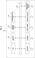
- FIG. 2 is a block diagram showing a hardware configuration of the image forming apparatus 10.
- the image forming apparatus 10 includes a CPU 31, a memory 32, a storage device 33 such as a hard disk drive, a communication interface (abbreviated as IF) 34 that transmits and receives data to and from an external device or the like via a network, a user interface (abbreviated as UI) device 35 including a touch panel or a liquid crystal display, and a keyboard, a scanner 36, a print engine 37, the imaging device 18, and the irradiation device 20. These components are connected to each other via the control bus 40.
- IF communication interface
- UI user interface
- the communication IF 34 transmits and receives data to and from an external device or the like.
- the UI device 35 receives an instruction input from the user.
- the scanner 36 scans the document loaded in the image forming apparatus 10 as image data.
- the print engine 37 prints an image on a recording medium such as printing paper through steps such as charging, exposure, development, transfer, and fixing.
- the CPU 31 is a processor that controls the operation of the image forming apparatus 10 by executing a predetermined process based on a control program stored in the memory 32 or the storage device 33.
- the control program may be provided in a form recorded on a computer-readable recording medium.
- this program may be provided in the form recorded on an optical disk such as a compact disc (CD)-read only memory (ROM) and a digital versatile disc (DVD)-ROM, or the form recorded on a semiconductor memory such as a universal serial bus (USB) memory and a memory card.
- the control program may be acquired from an external device via a communication line connected to the communication IF 34.
- FIG. 3 is a block diagram showing a functional configuration of the image forming apparatus 10.
- the image forming apparatus 10 includes a control unit 41, a communication unit 42, a display input unit 43, a storage unit 44, an image scanning unit 45, an image forming unit 46, an image output unit 47, an imaging unit 48, and an irradiation unit 49.
- the control unit 41 controls the overall operation of the image forming apparatus 10, and for example, based on an instruction input from the user, performs control of imaging the document by the imaging unit 48, control of outputting printing data such as a document image by the image output unit 47, or the like.
- the communication unit 42 transmits and receives data to and from an external device.
- the display input unit 43 displays various types of information on the display screen of the operation panel 22, based on the control by the control unit 41. Further, the display input unit 43 inputs various types of operation information performed by the user on the operation panel 22.
- the display input unit 43 is an example of a display unit in the technique of the present disclosure.
- the storage unit 44 stores various types of data such as image data generated by the control unit 41 in addition to the control program.
- the image scanning unit 45 performs a scanning operation of scanning various documents, based on the control by the control unit 41.
- the image forming unit 46 forms an image to be output from the image output unit 47, based on the control by the control unit 41.
- the image output unit 47 outputs the image formed by the image forming unit 46 onto a recording medium such as printing paper, based on the control by the control unit 41.
- the imaging unit 48 images the document placed on the placement unit 16, based on the control by the control unit 41.
- the irradiation unit 49 irradiates the document placed on the placement unit 16 with light, based on the control by the control unit 41.
- the image forming apparatus 10 of the present exemplary embodiment images a plurality of related documents, for example, such as the front side and the back side of a business card, one by one in order, and associates the acquired images of the plurality of documents with each other, thereby managing the images of the plurality of related documents as a group.
- a plurality of related documents for example, such as the front side and the back side of a business card
- a plurality of sheets of documents including one sheet of a document of each set may be simultaneously imaged.
- documents of each set are placed within a range in which the documents can be regarded as the same set of documents for each imaging, it is not possible to associate the images of documents of each set.
- the control unit 41 displays guidance information for guiding a placement position of the document of each set to be superimposed on the image imaged by the imaging unit 48 and representing a current state, on the display input unit 43, in second and subsequent imaging, by using information pertaining to documents acquired in past imaging.
- the "plurality of documents included in each set" may be, for example, a front-side document and a back-side document of one medium such as a business card, or may be documents of a plurality of media. Further, the documents of a plurality of media may be included in one set, and both sides of the front-side document and the back-side document may be used as the documents for some of the media.
- At least two or more sets may be mixed, among a set consisting of a front-side document and a back-side document of one medium, a set consisting of documents of a plurality of media, and a set of documents of a plurality of media and having both sides of the front-side document and the back-side document for some of the media as documents.
- two sets each consisting of a front-side document and a back-side document of one medium are simultaneously imaged.
- the "image representing the current state captured by the imaging unit 48" may be a still image or a moving image.
- a moving image representing the current state is displayed on the display input unit 43.
- a moving image showing the current state is also called a live view.
- a moving image showing the current state will be referred to as a live view.
- Fig. 4 is a diagram illustrating an example of documents of each of a plurality of sets to be simultaneously imaged.
- the set G1 consists of a front-side document of the medium 1 and a back-side document of the medium 1.
- the set G2 consists of a front-side document of the medium 2 and a back-side document of the medium 2.
- the front-side document of the medium 1 of the set G1 and the front-side document of the medium 2 of the set G2 are simultaneously imaged
- the back-side document of the medium 1 of the set G1 and the back-side document of the medium 2 of the set G2 are simultaneously imaged.
- Fig. 5 is a diagram showing an example of a display state of the live view at the time of the first imaging for the two sets G1 and G2.
- Fig. 6 is a diagram showing an example of the entire image IE acquired in the first imaging.
- control unit 41 displays the live view LE imaged by the imaging unit 48 on the display input unit 43.
- the front-side document of the medium 1 of the set G1 and the front-side document of the medium 2 of the set G2 are placed on the placement unit 16 by the user.
- the live view image L1a of the front-side document of the medium 1 and the live view image L2a of the front-side document of the medium 2 are displayed in the live view LE, as shown in Fig. 5 .
- the user checks the live view LE displayed on the display input unit 43, and inputs an imaging instruction to the image forming apparatus 10.
- the control unit 41 receives the input of the imaging instruction from the user to perform the first imaging, and acquires an entire image IE in which the front-side document of the medium 1 and the front-side document of the medium 2 are shown, as shown in Fig. 6 . Next, the control unit 41 extracts the image I1a of the front-side document of the medium 1 and the image I2a of the front-side document of the medium 2, from the entire image IE.
- Fig. 7 is a diagram showing an example of a display state of a live view at the time of the second imaging for the two sets G1 and G2, and is a diagram showing a state before a new document is placed.
- Fig. 8 is a diagram showing an example of a display state of a live view at the time of the second imaging for the two sets G1 and G2, and is a diagram showing a state after a new document is placed.
- Fig. 9 is a diagram showing an example of a display state of a live view at the time of the second imaging for the two sets G1 and G2, and is a diagram showing a state after a new document is placed and alignment is performed.
- Fig. 10 is a diagram showing an example of the entire image IE acquired in the second imaging.
- the control unit 41 superimposes the image I1a of the front-side document of the medium 1 and the image I2a of the front-side document of the medium 2 acquired at the time of the first imaging as the guidance information, on the front side of the live view LE and displays the images at the same position as at the time of the first imaging.
- the image I1a of the front-side document of the medium 1 and the image I2a of the front-side document of the medium 2 to be displayed as the guidance information may be displayed in the acquired state, or may be displayed after adjusting the brightness or chroma such that the images can be easily distinguished from the document imaged during the second time.
- a case where the image I1a of the front-side document of the medium 1 and the image I2a of the front-side document of the medium 2 are displayed with reduced brightness is shown.
- the back-side document of the medium 1 of the set G1 and the back-side document of the medium 2 of the set G2 are placed on the placement unit 16 by the user.
- the live view image L1b of the back-side document of the medium 1 and the live view image L2b of the back-side document of the medium 2 are displayed in the live view LE, as shown in Fig. 8 .
- the user checks the live view LE and the guidance information (the image I1a of the front-side document of the medium 1 and the image I2a of the front-side document of the medium 2 acquired at the time of the first imaging) displayed on the display input unit 43, and aligns the document for the second imaging.
- the user aligns the back-side document of the medium 1 such that the image I1a of the front-side document of the medium 1 and the live view image L1b of the back-side document of the medium 1 overlap. Further, the user aligns the back-side document of the medium 2 such that the image I2a of the front-side document of the medium 2 and the live view image L2b of the back-side document of the medium 2 overlap.
- the user checks the live view LE displayed on the display input unit 43, and inputs an imaging instruction to the image forming apparatus 10.
- the control unit 41 receives the input of the imaging instruction from the user to perform the second imaging, and acquires an entire image IE in which the back-side document of the medium 1 and the back-side document of the medium 2 are shown, as shown in Fig. 10 . Next, the control unit 41 extracts the image I1b of the back-side document of the medium 1 and the image I2b of the back-side document of the medium 2, from the entire image IE.
- the user can place the front-side document and the back-side document of each medium in the position where the front-side document and the back-side document overlap each other, in the first imaging and the second imaging.
- the control unit 41 manages the image I1a of the front-side document of the medium 1 acquired at the time of the first imaging and the image I1b of the back-side document of the medium 1 shown at a position overlapping the image I1a of the front-side document of the medium 1 at the time of the second imaging in association with the documents of the set G1. Similarly, the control unit 41 manages the image I2a of the front-side document of the medium 2 acquired at the time of the first imaging and the image I2b of the back-side document of the medium 2 shown at a position overlapping the image I2a of the front-side document of the medium 2 at the time of the second imaging in association with the documents of the set G2.
- the image of the back-side document shown at a position overlapping the image of the front-side document is not limited to an aspect in which the image of the front-side document and the image of the back-side document completely overlap each other, and may be an aspect in which the image of the front-side document and the image of the back-side document partially overlap each other.
- the method of determining whether or not the image of the front-side document overlaps the image of the back-side document is not particularly limited, and any method may be used. For example, in a case where the area where the image of the back-side document overlaps the image of the front-side document is equal to or more than a set threshold value, it may be determined that the two images overlap, and in a case where the area is less than the threshold value, it may be determined that the two images do not overlap.
- the threshold value may be, for example, 50% or more.
- a job such as file transfer, fax, or printing may be executed on one document file of each set, based on a user's instruction.
- the guidance information may be images in a state in which the images of the documents acquired in the past imaging are made transparent at a preset transparency, as shown in Fig. 11 .
- the user can visually recognize the document for the second imaging.
- the guidance information may be the images IF1 and IF2 of a frame representing the outline of each document acquired in the past imaging.
- the guidance information may include an image indicating at least one of the up, down, right, or left directions of each document.
- Fig. 13 shows an example in which arrows IA1 and IA2 indicating the upward direction of each document are displayed.
- control unit 41 may change the transparency in displaying the guidance information in accordance with the user operation.
- control unit 41 may switch between the display state and the hidden state of the guidance information in accordance with the user operation.
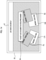
- control unit 41 may cause the notification display image IN in which a message such as "Please place the document in an overlapping manner.” is described to be superimposed on the live view LE and displayed.
- the method of determining whether or not the document and the guidance information overlap is not particularly limited, and any method may be used. For example, in a case where the area where the document area overlaps with the display area of the guidance information is equal to or greater than a set threshold value, it may be determined that the document and the guidance information overlap each other, and in a case where the area is less than the threshold value, it may be determined that the document and the guidance information do not overlap each other.
- the threshold value may be, for example, 50% or more.
- step S11 the control unit 41 starts displaying the live view in step S12.
- double-sided imaging means that, as described above, both sides of the front-side document and the back-side document of each of a plurality of media are imaged. Further, it is assumed that the front-side document of each of the plurality of media is imaged in the first imaging and the back-side document of each of the plurality of media is imaged in the second imaging.
- step S13 the control unit 41 determines whether either imaging of the front-side document of the medium or imaging of the back-side document is performed.
- step S13 In a case where it is determined in step S13 that the front side imaging, that is, the first imaging is performed, the control unit 41 performs imaging of the front-side document of each of the plurality of media in step S14, records the document position of the front-side document of each of the plurality of media in the front-side captured image in step S 15, and transitions to step S12.
- control unit 41 uses the front-side document of each of the plurality of media acquired in the first imaging to display guidance information in step S 16, and images the back-side document of each of the plurality of media in step S17.
- step S 18 the control unit 41 performs matching between the front-side document and the back-side document for each medium, and manages the documents for each set.
- the matching means a process of combining a front-side document and a back-side document of the same medium.
- step S19 the control unit 41 executes a job such as file transfer, fax, or printing on the images of the documents of each set, based on the instruction of the user, and transitions to step S 11.
- a job such as file transfer, fax, or printing on the images of the documents of each set, based on the instruction of the user, and transitions to step S 11.
- the present invention is not limited to the above exemplary embodiment and may be appropriately modified.
- processor refers to hardware in a broad sense.
- Examples of the processor include general processors (e.g., CPU: Central Processing Unit) and dedicated processors (e.g., GPU: Graphics Processing Unit, ASIC: Application Specific Integrated Circuit, FPGA: Field Programmable Gate Array, and programmable logic device).
- processor is broad enough to encompass one processor or plural processors in collaboration which are located physically apart from each other but may work cooperatively.
- the order of operations of the processor is not limited to one described in the embodiments above, and may be changed.
- the present invention is not limited thereto, and the present invention can also be applied to various types of image processing apparatuses such as a mobile phone, a tablet, or a personal computer.
- the content of the guidance information can be simply displayed with only a frame line.
- related documents can be associated with each other by being aligned vertically and horizontally.
- a density at which the guidance information is displayed can be adjusted according to the preference of the user.
- the image of the front-side document and the image of the back-side document can be associated with each other.
Landscapes
- Engineering & Computer Science (AREA)
- Multimedia (AREA)
- Signal Processing (AREA)
- Human Computer Interaction (AREA)
- Facsimiles In General (AREA)
- Health & Medical Sciences (AREA)
- Biomedical Technology (AREA)
- General Health & Medical Sciences (AREA)
- Editing Of Facsimile Originals (AREA)
Abstract
Description
- The present invention relates to an image processing apparatus, a program, and an image processing method.
-
JP6737341B - In an image processing apparatus such as a multifunction machine, an imaging unit such as a camera may be provided, and an image may be acquired by imaging a document by using the imaging unit.
- In this case, for example, a plurality of related documents such as the front side and the back side of a business card are imaged one by one in order, and the acquired images of the plurality of documents are associated with each other, thereby managing the images of the plurality of related documents as a group.
- In a case where there are a plurality of sets each consisting of a plurality of related documents, and a plurality of sheets of documents including one sheet of document of each set are simultaneously imaged, unless documents of each set are placed within a range in which the documents can be regarded as the same set of documents for each imaging, it is not possible to associate the images of documents of each set.
- An object of the present invention is to provide an image processing apparatus, a program, and an image processing method capable of allowing a user to know a position where the document of each set is placed, in a case where there are a plurality of sets each consisting of a plurality of documents and a plurality of sheets of documents including one sheet of document of each set are simultaneously imaged.
- According to a first aspect of the present disclosure, there is provided an image processing apparatus including a processor configured to: display, in a case where there are a plurality of sets each consisting of a plurality of documents, and a plurality of sheets of documents including at least one sheet of a document of each of all or part of the plurality of sets are simultaneously imaged by an imaging unit that images a document, guidance information for guiding a placement position of the document of each set to be superimposed on an image imaged by the imaging unit and representing a current state, on a display unit, in second and subsequent imaging, by using information pertaining to documents acquired in past imaging.
- According to a second aspect of the present disclosure, there is provided the image processing apparatus according to the first aspect, in which the guidance information may be images of the documents acquired in the past imaging.
- According to a third aspect of the present disclosure, there is provided the image processing apparatus according to the second aspect, in which the guidance information may be images in a state in which the images of the documents acquired in the past imaging are made transparent at a preset transparency.
- According to a fourth aspect of the present disclosure, there is provided the image processing apparatus according to the first aspect, in which the guidance information may be an image of a frame representing an outline of each document acquired in the past imaging.
- According to a fifth aspect of the present disclosure, there is provided the image processing apparatus according to the fourth aspect, in which the guidance information may include an image indicating at least one of up, down, right, or left directions of each document.
- According to a sixth aspect of the present disclosure, there is provided the image processing apparatus according to any one of the first to fifth aspects, in which the processor may be configured to change a transparency in displaying the guidance information in accordance with a user operation.
- According to a seventh aspect of the present disclosure, there is provided the image processing apparatus according to any one of the first to sixth aspects, in which the processor may be configured to switch between a display state and a hidden state of the guidance information in accordance with a user operation.
- According to an eighth aspect of the present disclosure, there is provided the image processing apparatus according to any one of the first to seventh aspects, in which the plurality of documents included in each set may be a front-side document and a back-side document of one medium.
- According to a ninth aspect of the present disclosure, there is provided a program causing a computer to execute a process including: displaying, in a case where there are a plurality of sets each consisting of a plurality of documents, and a plurality of sheets of documents including at least one sheet of a document of each of all or part of the plurality of sets are simultaneously imaged by an imaging unit that images a document, guidance information for guiding a placement position of the document of each set to be superimposed on an image imaged by the imaging unit and representing a current state, on a display unit, in second and subsequent imaging, by using information pertaining to documents acquired in past imaging.
- According to a tenth aspect of the present disclosure, there is provided an image processing method including: displaying, in a case where there are a plurality of sets each consisting of a plurality of documents, and a plurality of sheets of documents including at least one sheet of a document of each of all or part of the plurality of sets are simultaneously imaged by an imaging unit that images a document, guidance information for guiding a placement position of the document of each set to be superimposed on an image imaged by the imaging unit and representing a current state, on a display unit, in second and subsequent imaging, by using information pertaining to documents acquired in past imaging.
- According to the image processing apparatus of the first aspect, in a case where there are a plurality of sets each consisting of a plurality of related documents, and a plurality of sheets of documents including one sheet of a document of each set are simultaneously imaged, a user is allowed to know a position where the document of each set is placed.
- According to the image processing apparatus of the second aspect, it is possible to guide the placement position while checking the content of the image captured in the past.
- According to the image processing apparatus of the third aspect, even in a case where the guidance information and the image of the document to be newly imaged overlap each other in the moving image representing the current state, the contents of both images can be visually recognized.
- According to the image processing apparatus of the fourth aspect, the content of the guidance information can be simply displayed with only a frame line.
- According to the image processing apparatus of the fifth aspect, related documents can be associated with each other by being aligned vertically and horizontally.
- According to the image processing apparatus of the sixth aspect, a density at which the guidance information is displayed can be adjusted according to the preference of the user.
- According to the image processing apparatus of the seventh aspect, it is possible to facilitate checking of an image of a document to be newly captured, as compared with a case where the guidance information is always displayed.
- According to the image processing apparatus of the eighth aspect, for a medium having a front-side document and a back-side document, the image of the front-side document and the image of the back-side document can be associated with each other.
- According to the program of the ninth aspect, in a case where there are a plurality of sets each consisting of a plurality of related documents, and a plurality of sheets of documents including one sheet of a document of each set are simultaneously imaged, a user is allowed to know a position where the document of each set is placed.
- According to the image processing method of the tenth aspect, in a case where there are a plurality of sets each consisting of a plurality of related documents, and a plurality of sheets of documents including one sheet of a document of each set are simultaneously imaged, a user is allowed to know a position where the document of each set is placed.
- Exemplary embodiment(s) of the present invention will be described in detail based on the following figures, wherein:
-
Figs. 1A and 1B are views showing an external appearance of an image forming apparatus according to an exemplary embodiment of the present invention, whereFig. 1A is a side view of the image forming apparatus andFig. 1B is a front view of the image forming apparatus; -
Fig. 2 is a block diagram showing a hardware configuration of the image forming apparatus; -
Fig. 3 is a block diagram showing a functional configuration of the image forming apparatus; -
Fig. 4 is a diagram illustrating an example of documents of each of a plurality of sets to be simultaneously imaged; -
Fig. 5 is a diagram showing an example of a display state of a live view at the time of first imaging for two sets; -
Fig. 6 is a diagram showing an example of an entire image acquired in the first imaging; -
Fig. 7 is a diagram showing an example of a display state of a live view at the time of second imaging for the two sets, and is a diagram showing a state before a new document is placed; -
Fig. 8 is a diagram showing an example of a display state of a live view at the time of the second imaging for the two sets, and is a diagram showing a state after the new document is placed; -
Fig. 9 is a diagram showing an example of a display state of a live view at the time of the second imaging for the two sets, and is a diagram showing a state after the new document is placed and alignment is performed; -
Fig. 10 is a diagram showing an example of an entire image acquired in the second imaging; -
Fig. 11 is a diagram showing another example of the display state of the live view at the time of the second imaging for the two sets; -
Fig. 12 is a diagram showing another example of the display state of the live view at the time of the second imaging for the two sets; -
Fig. 13 is a diagram showing another example of the display state of the live view at the time of the second imaging for the two sets; -
Fig. 14 is a diagram showing another example of the display state of the live view at the time of the second imaging for the two sets; and -
Fig. 15 is a flowchart showing a processing flow at the time of imaging a document in the image forming apparatus. - Hereinafter, an exemplary embodiment of the present invention will be described in detail with reference to the accompanying drawings.
Figs. 1A and 1B are views showing an external appearance of animage forming apparatus 10 as an example of an image processing apparatus according to an exemplary embodiment of the present invention, whereFig. 1A is a side view of theimage forming apparatus 10 andFig. 1B is a front view of theimage forming apparatus 10. Theimage forming apparatus 10 is an apparatus installed in an office such as a multifunction machine. - As shown in
Fig. 1 , theimage forming apparatus 10 includes an apparatusmain body 12, adischarge tray 14 as a medium discharge unit, aplacement unit 16, animaging device 18, anirradiation device 20 including fourlight sources operation panel 22, or the like. - The
discharge tray 14 is where paper, which is an example of a medium, is discharged. Further, thedischarge tray 14 is provided at a position where the medium is taken out by the user in a standing state. - The
placement unit 16 is a top surface of the apparatusmain body 12, to be described in detail later, and is disposed on an upper portion of the apparatusmain body 12. Further, theplacement unit 16 is installed above thedischarge tray 14 in the vertical direction. Further, theplacement unit 16 is configured such that a document such as a paper, a business card, or a receipt can be placed. - The
imaging device 18 includes an imaging element such as a charge coupled device (CCD), for example, and images a subject such as a document to acquire image data. Theimaging device 18 is installed above theplacement unit 16, and is configured to image the document placed on theplacement unit 16 from above. Here, in a case where the upper surface of theplacement unit 16 is used as the reference plane, the term "above theplacement unit 16" is not limited to the position vertically above the reference plane, and means a position that is above in the vertical direction and is higher than the reference plane. - Further, a
column 24 is provided on the top surface of the apparatusmain body 12 and on the back of the upper surface of theplacement unit 16. Thecolumn 24 extends upward substantially perpendicular to the upper surface of theplacement unit 16, and is provided with an end portion bent above theplacement unit 16. Theimaging device 18 is attached to an end portion of thecolumn 24. - An image forming unit, which forms an image of a subject placed on the
placement unit 16, is provided between thedischarge tray 14 and theplacement unit 16. That is, an image forming unit that forms an image on the paper discharged to thedischarge tray 14 is provided above thedischarge tray 14. - The
irradiation device 20 includes one or more light sources such as, for example, a light emitting diode (LED), and includes, for example, thelight sources light sources column 24. That is, thelight sources placement unit 16. - Specifically, the
light sources imaging device 18, downward on both sides of theimaging device 18 of thecolumn 24. Thelight sources operation panel 22, obliquely downward on both sides of thecolumn 24 at the lower end of theoperation panel 22. - That is, the
light sources light sources placement unit 16. That is, thelight sources placement unit 16 is improved. - The
operation panel 22 includes a display screen, and is configured to set theimage forming apparatus 10. Theoperation panel 22 is installed on thecolumn 24 between theplacement unit 16 and theimaging device 18, at the back of the apparatusmain body 12. - A document feeder having a double-sided simultaneous scanning function is provided inside the apparatus
main body 12 below the top plate of theplacement unit 16. It is configured that the document feeder can be used by sliding a part of the top plate of theplacement unit 16 in the plane direction. - Next, the hardware configuration of the
image forming apparatus 10 of the present exemplary embodiment will be described.Fig. 2 is a block diagram showing a hardware configuration of theimage forming apparatus 10. - As shown in
Fig. 2 , theimage forming apparatus 10 includes aCPU 31, amemory 32, astorage device 33 such as a hard disk drive, a communication interface (abbreviated as IF) 34 that transmits and receives data to and from an external device or the like via a network, a user interface (abbreviated as UI)device 35 including a touch panel or a liquid crystal display, and a keyboard, ascanner 36, aprint engine 37, theimaging device 18, and theirradiation device 20. These components are connected to each other via thecontrol bus 40. - The communication IF 34 transmits and receives data to and from an external device or the like. The
UI device 35 receives an instruction input from the user. Thescanner 36 scans the document loaded in theimage forming apparatus 10 as image data. Theprint engine 37 prints an image on a recording medium such as printing paper through steps such as charging, exposure, development, transfer, and fixing. - The
CPU 31 is a processor that controls the operation of theimage forming apparatus 10 by executing a predetermined process based on a control program stored in thememory 32 or thestorage device 33. In the present exemplary embodiment, it has been described that theCPU 31 reads and executes the control program stored in thememory 32 or thestorage device 33, but the present invention is not limited thereto. The control program may be provided in a form recorded on a computer-readable recording medium. For example, this program may be provided in the form recorded on an optical disk such as a compact disc (CD)-read only memory (ROM) and a digital versatile disc (DVD)-ROM, or the form recorded on a semiconductor memory such as a universal serial bus (USB) memory and a memory card. Further, the control program may be acquired from an external device via a communication line connected to the communication IF 34. - Next, the functional configuration of the
image forming apparatus 10 of the present exemplary embodiment will be described.Fig. 3 is a block diagram showing a functional configuration of theimage forming apparatus 10. - As shown in
Fig. 3 , theimage forming apparatus 10 includes acontrol unit 41, acommunication unit 42, adisplay input unit 43, astorage unit 44, animage scanning unit 45, animage forming unit 46, animage output unit 47, animaging unit 48, and anirradiation unit 49. - The
control unit 41 controls the overall operation of theimage forming apparatus 10, and for example, based on an instruction input from the user, performs control of imaging the document by theimaging unit 48, control of outputting printing data such as a document image by theimage output unit 47, or the like. - The
communication unit 42 transmits and receives data to and from an external device. Thedisplay input unit 43 displays various types of information on the display screen of theoperation panel 22, based on the control by thecontrol unit 41. Further, thedisplay input unit 43 inputs various types of operation information performed by the user on theoperation panel 22. Thedisplay input unit 43 is an example of a display unit in the technique of the present disclosure. Thestorage unit 44 stores various types of data such as image data generated by thecontrol unit 41 in addition to the control program. - The
image scanning unit 45 performs a scanning operation of scanning various documents, based on the control by thecontrol unit 41. Theimage forming unit 46 forms an image to be output from theimage output unit 47, based on the control by thecontrol unit 41. Theimage output unit 47 outputs the image formed by theimage forming unit 46 onto a recording medium such as printing paper, based on the control by thecontrol unit 41. - The
imaging unit 48 images the document placed on theplacement unit 16, based on the control by thecontrol unit 41. Theirradiation unit 49 irradiates the document placed on theplacement unit 16 with light, based on the control by thecontrol unit 41. - The
image forming apparatus 10 of the present exemplary embodiment images a plurality of related documents, for example, such as the front side and the back side of a business card, one by one in order, and associates the acquired images of the plurality of documents with each other, thereby managing the images of the plurality of related documents as a group. - Further, in a case where there are a plurality of sets each consisting of a plurality of documents, a plurality of sheets of documents including one sheet of a document of each set may be simultaneously imaged. In this case, unless documents of each set are placed within a range in which the documents can be regarded as the same set of documents for each imaging, it is not possible to associate the images of documents of each set.
- Therefore, in the present exemplary embodiment, in a case where there are a plurality of sets each consisting of a plurality of documents, and a plurality of sheets of documents including at least one sheet of a document of each of all or part of the plurality of sets are simultaneously imaged by the
imaging unit 48, thecontrol unit 41 displays guidance information for guiding a placement position of the document of each set to be superimposed on the image imaged by theimaging unit 48 and representing a current state, on thedisplay input unit 43, in second and subsequent imaging, by using information pertaining to documents acquired in past imaging. - Here, the "plurality of documents included in each set" may be, for example, a front-side document and a back-side document of one medium such as a business card, or may be documents of a plurality of media. Further, the documents of a plurality of media may be included in one set, and both sides of the front-side document and the back-side document may be used as the documents for some of the media.
- Further, regarding a set for simultaneous imaging, at least two or more sets may be mixed, among a set consisting of a front-side document and a back-side document of one medium, a set consisting of documents of a plurality of media, and a set of documents of a plurality of media and having both sides of the front-side document and the back-side document for some of the media as documents.
- In the present exemplary embodiment, as an example, two sets each consisting of a front-side document and a back-side document of one medium are simultaneously imaged.
- Further, the "image representing the current state captured by the
imaging unit 48" may be a still image or a moving image. In the present exemplary embodiment, as an example, a moving image representing the current state is displayed on thedisplay input unit 43. In addition, a moving image showing the current state is also called a live view. In the following description, a moving image showing the current state will be referred to as a live view. - Hereinafter, the process in the
image forming apparatus 10 of the present exemplary embodiment will be described in detail. First, documents of each of a plurality of sets to be simultaneously imaged will be described.Fig. 4 is a diagram illustrating an example of documents of each of a plurality of sets to be simultaneously imaged. - As shown in
Fig. 4 , in the present exemplary embodiment, a case where two sets of documents G1 and G2 are simultaneously imaged will be described as an example. The set G1 consists of a front-side document of themedium 1 and a back-side document of themedium 1. The set G2 consists of a front-side document of themedium 2 and a back-side document of themedium 2. - In the first imaging, the front-side document of the
medium 1 of the set G1 and the front-side document of themedium 2 of the set G2 are simultaneously imaged, and in the second imaging, the back-side document of themedium 1 of the set G1 and the back-side document of themedium 2 of the set G2 are simultaneously imaged. -
Fig. 5 is a diagram showing an example of a display state of the live view at the time of the first imaging for the two sets G1 and G2.Fig. 6 is a diagram showing an example of the entire image IE acquired in the first imaging. - At the time of imaging the document, the
control unit 41 displays the live view LE imaged by theimaging unit 48 on thedisplay input unit 43. - In the first imaging, the front-side document of the
medium 1 of the set G1 and the front-side document of themedium 2 of the set G2 are placed on theplacement unit 16 by the user. - In a case where the document is placed on the
placement unit 16, the live view image L1a of the front-side document of themedium 1 and the live view image L2a of the front-side document of the medium 2 are displayed in the live view LE, as shown inFig. 5 . - The user checks the live view LE displayed on the
display input unit 43, and inputs an imaging instruction to theimage forming apparatus 10. - The
control unit 41 receives the input of the imaging instruction from the user to perform the first imaging, and acquires an entire image IE in which the front-side document of themedium 1 and the front-side document of the medium 2 are shown, as shown inFig. 6 . Next, thecontrol unit 41 extracts the image I1a of the front-side document of themedium 1 and the image I2a of the front-side document of themedium 2, from the entire image IE. -
Fig. 7 is a diagram showing an example of a display state of a live view at the time of the second imaging for the two sets G1 and G2, and is a diagram showing a state before a new document is placed.Fig. 8 is a diagram showing an example of a display state of a live view at the time of the second imaging for the two sets G1 and G2, and is a diagram showing a state after a new document is placed.Fig. 9 is a diagram showing an example of a display state of a live view at the time of the second imaging for the two sets G1 and G2, and is a diagram showing a state after a new document is placed and alignment is performed.Fig. 10 is a diagram showing an example of the entire image IE acquired in the second imaging. - At the time of the second imaging, as illustrated in
Fig. 7 , thecontrol unit 41 superimposes the image I1a of the front-side document of themedium 1 and the image I2a of the front-side document of the medium 2 acquired at the time of the first imaging as the guidance information, on the front side of the live view LE and displays the images at the same position as at the time of the first imaging. - The image I1a of the front-side document of the
medium 1 and the image I2a of the front-side document of the medium 2 to be displayed as the guidance information may be displayed in the acquired state, or may be displayed after adjusting the brightness or chroma such that the images can be easily distinguished from the document imaged during the second time. Here, as an example, a case where the image I1a of the front-side document of themedium 1 and the image I2a of the front-side document of the medium 2 are displayed with reduced brightness is shown. - In the second imaging, the back-side document of the
medium 1 of the set G1 and the back-side document of themedium 2 of the set G2 are placed on theplacement unit 16 by the user. - In a case where the document is placed on the
placement unit 16, the live view image L1b of the back-side document of themedium 1 and the live view image L2b of the back-side document of the medium 2 are displayed in the live view LE, as shown inFig. 8 . - The user checks the live view LE and the guidance information (the image I1a of the front-side document of the
medium 1 and the image I2a of the front-side document of the medium 2 acquired at the time of the first imaging) displayed on thedisplay input unit 43, and aligns the document for the second imaging. - Specifically, as shown in
Fig. 9 , the user aligns the back-side document of the medium 1 such that the image I1a of the front-side document of themedium 1 and the live view image L1b of the back-side document of the medium 1 overlap. Further, the user aligns the back-side document of the medium 2 such that the image I2a of the front-side document of themedium 2 and the live view image L2b of the back-side document of the medium 2 overlap. - The user checks the live view LE displayed on the
display input unit 43, and inputs an imaging instruction to theimage forming apparatus 10. - The
control unit 41 receives the input of the imaging instruction from the user to perform the second imaging, and acquires an entire image IE in which the back-side document of themedium 1 and the back-side document of the medium 2 are shown, as shown inFig. 10 . Next, thecontrol unit 41 extracts the image I1b of the back-side document of themedium 1 and the image I2b of the back-side document of themedium 2, from the entire image IE. - In this way, since the guidance information is superimposed on the live view LE and displayed at the time of the second imaging, the user can place the front-side document and the back-side document of each medium in the position where the front-side document and the back-side document overlap each other, in the first imaging and the second imaging.
- Therefore, the
control unit 41 manages the image I1a of the front-side document of the medium 1 acquired at the time of the first imaging and the image I1b of the back-side document of the medium 1 shown at a position overlapping the image I1a of the front-side document of the medium 1 at the time of the second imaging in association with the documents of the set G1. Similarly, thecontrol unit 41 manages the image I2a of the front-side document of the medium 2 acquired at the time of the first imaging and the image I2b of the back-side document of the medium 2 shown at a position overlapping the image I2a of the front-side document of the medium 2 at the time of the second imaging in association with the documents of the set G2. - Note that "the image of the back-side document shown at a position overlapping the image of the front-side document" is not limited to an aspect in which the image of the front-side document and the image of the back-side document completely overlap each other, and may be an aspect in which the image of the front-side document and the image of the back-side document partially overlap each other.
- The method of determining whether or not the image of the front-side document overlaps the image of the back-side document is not particularly limited, and any method may be used. For example, in a case where the area where the image of the back-side document overlaps the image of the front-side document is equal to or more than a set threshold value, it may be determined that the two images overlap, and in a case where the area is less than the threshold value, it may be determined that the two images do not overlap. In this case, the threshold value may be, for example, 50% or more.
- With respect to the image of a document of each set, for example, a job such as file transfer, fax, or printing may be executed on one document file of each set, based on a user's instruction.
- In addition to the images of the documents acquired in the past imaging as described above, the guidance information may be images in a state in which the images of the documents acquired in the past imaging are made transparent at a preset transparency, as shown in
Fig. 11 . - In such an aspect, at the time of the second imaging, in a case where the user aligns the document for the second imaging, even in a case where the document for the second imaging overlaps the guidance information, the user can visually recognize the document for the second imaging.
- Further, as shown in
Fig. 12 , the guidance information may be the images IF1 and IF2 of a frame representing the outline of each document acquired in the past imaging. - In this case, as shown in
Fig. 13 , the guidance information may include an image indicating at least one of the up, down, right, or left directions of each document.Fig. 13 shows an example in which arrows IA1 and IA2 indicating the upward direction of each document are displayed. - Further, the
control unit 41 may change the transparency in displaying the guidance information in accordance with the user operation. - Further, the
control unit 41 may switch between the display state and the hidden state of the guidance information in accordance with the user operation. - Further, in a case where the document is placed at a position where the document does not overlap with the guidance information, at the time of the second and subsequent imaging, for example, as shown in
Fig. 14 , thecontrol unit 41 may cause the notification display image IN in which a message such as "Please place the document in an overlapping manner." is described to be superimposed on the live view LE and displayed. - The method of determining whether or not the document and the guidance information overlap is not particularly limited, and any method may be used. For example, in a case where the area where the document area overlaps with the display area of the guidance information is equal to or greater than a set threshold value, it may be determined that the document and the guidance information overlap each other, and in a case where the area is less than the threshold value, it may be determined that the document and the guidance information do not overlap each other. In this case, the threshold value may be, for example, 50% or more.
- Next, a process at the time of imaging a document in the
image forming apparatus 10 will be described with reference to the flowchart ofFig. 15 . - First, in a case where in step S11, the user selects the double-sided imaging, the
control unit 41 starts displaying the live view in step S12. Here, "double-sided imaging" means that, as described above, both sides of the front-side document and the back-side document of each of a plurality of media are imaged. Further, it is assumed that the front-side document of each of the plurality of media is imaged in the first imaging and the back-side document of each of the plurality of media is imaged in the second imaging. - Next, in step S13, the
control unit 41 determines whether either imaging of the front-side document of the medium or imaging of the back-side document is performed. - In a case where it is determined in step S13 that the front side imaging, that is, the first imaging is performed, the
control unit 41 performs imaging of the front-side document of each of the plurality of media in step S14, records the document position of the front-side document of each of the plurality of media in the front-side captured image instep S 15, and transitions to step S12. - In a case where it is determined in step S13 that the back side imaging, that is, the second imaging is performed, the
control unit 41 uses the front-side document of each of the plurality of media acquired in the first imaging to display guidance information instep S 16, and images the back-side document of each of the plurality of media in step S17. - Next, in
step S 18, thecontrol unit 41 performs matching between the front-side document and the back-side document for each medium, and manages the documents for each set. Here, the matching means a process of combining a front-side document and a back-side document of the same medium. - Finally, in step S19, the
control unit 41 executes a job such as file transfer, fax, or printing on the images of the documents of each set, based on the instruction of the user, and transitions to stepS 11. - Although the image forming apparatus according to the exemplary embodiment of the present invention has been described above, the present invention is not limited to the above exemplary embodiment and may be appropriately modified.
- In the embodiments above, the term "processor" refers to hardware in a broad sense. Examples of the processor include general processors (e.g., CPU: Central Processing Unit) and dedicated processors (e.g., GPU: Graphics Processing Unit, ASIC: Application Specific Integrated Circuit, FPGA: Field Programmable Gate Array, and programmable logic device).
- In the embodiments above, the term "processor" is broad enough to encompass one processor or plural processors in collaboration which are located physically apart from each other but may work cooperatively. The order of operations of the processor is not limited to one described in the embodiments above, and may be changed.
- Further, in the above exemplary embodiment, the case where the present invention is applied to the image forming apparatus has been described, but the present invention is not limited thereto, and the present invention can also be applied to various types of image processing apparatuses such as a mobile phone, a tablet, or a personal computer.
- Hereinafter, aspects of the present disclosure will be described.
- (((1))) An image processing apparatus comprising:
a processor configured to:
display, in a case where there are a plurality of sets each consisting of a plurality of documents, and a plurality of sheets of documents including at least one sheet of a document of each of all or part of the plurality of sets are simultaneously imaged by an imaging unit that images a document, guidance information for guiding a placement position of the document of each set to be superimposed on an image imaged by the imaging unit and representing a current state, on a display unit, in second and subsequent imaging, by using information pertaining to documents acquired in past imaging. - (((2))) The image processing apparatus according to (((1))),
wherein the guidance information is images of the documents acquired in the past imaging. - (((3))) The image processing apparatus according to (((2))),
wherein the guidance information is images in a state in which the images of the documents acquired in the past imaging are made transparent at a preset transparency. - (((4))) The image processing apparatus according to (((1))),
wherein the guidance information is an image of a frame representing an outline of each document acquired in the past imaging. - (((5))) The image processing apparatus according to (((4))),
wherein the guidance information includes an image indicating at least one of up, down, right, or left directions of each document. - (((6))) The image processing apparatus according to any one of (((1))) to (((5))), wherein the processor is configured to:
change a transparency in displaying the guidance information in accordance with a user operation. - (((7))) The image processing apparatus according to any one of (((1))) to (((6))), wherein the processor is configured to:
switch between a display state and a hidden state of the guidance information in accordance with a user operation. - (((8))) The image processing apparatus according to any one of (((1))) to (((7))),
wherein the plurality of documents included in each set are a front-side document and a back-side document of one medium. - (((9))) A program causing a computer to execute a process comprising:
displaying, in a case where there are a plurality of sets each consisting of a plurality of documents, and a plurality of sheets of documents including at least one sheet of a document of each of all or part of the plurality of sets are simultaneously imaged by an imaging unit that images a document, guidance information for guiding a placement position of the document of each set to be superimposed on an image imaged by the imaging unit and representing a current state, on a display unit, in second and subsequent imaging, by using information pertaining to documents acquired in past imaging. - The effects of the supplementary notes will be described below.
- According to the image processing apparatus of (((1))), in a case where there are a plurality of sets each consisting of a plurality of related documents, and a plurality of sheets of documents including one sheet of a document of each set are simultaneously imaged, a user is allowed to know a position where the document of each set is placed.
- According to the image processing apparatus of (((2))), it is possible to guide the placement position while checking the content of the image captured in the past.
- According to the image processing apparatus of (((3))), even in a case where the guidance information and the image of the document to be newly imaged overlap each other in the moving image representing the current state, the contents of both images can be visually recognized.
- According to the image processing apparatus of (((4))), the content of the guidance information can be simply displayed with only a frame line.
- According to the image processing apparatus of (((5))), related documents can be associated with each other by being aligned vertically and horizontally.
- According to the image processing apparatus of (((6))), a density at which the guidance information is displayed can be adjusted according to the preference of the user.
- According to the image processing apparatus of (((7))), it is possible to facilitate checking of an image of a document to be newly captured, as compared with a case where the guidance information is always displayed.
- According to the image processing apparatus of (((8))), for a medium having a front-side document and a back-side document, the image of the front-side document and the image of the back-side document can be associated with each other.
- According to the program of (((9))), in a case where there are a plurality of sets each consisting of a plurality of related documents, and a plurality of sheets of documents including one sheet of a document of each set are simultaneously imaged, a user is allowed to know a position where the document of each set is placed.
- The foregoing description of the exemplary embodiments of the present invention has been provided for the purposes of illustration and description. It is not intended to be exhaustive or to limit the invention to the precise forms disclosed. Obviously, many modifications and variations will be apparent to practitioners skilled in the art. The embodiments were chosen and described in order to best explain the principles of the invention and its practical applications, thereby enabling others skilled in the art to understand the invention for various embodiments and with the various modifications as are suited to the particular use contemplated. It is intended that the scope of the invention be defined by the following claims and their equivalents.
-
- 10: image forming apparatus
- 12: apparatus main body
- 14: discharge tray
- 16: placement unit
- 18: imaging device
- 20: irradiation device
- 22: operation panel
- 24: column
- 31: CPU
- 32: memory
- 33: storage device
- 34: communication interface
- 35: user interface device
- 36: scanner
- 37: print engine
- 40: control bus
- 41: control unit
- 42: communication unit
- 43: display input unit
- 44: storage unit
- 45: image scanning unit
- 46: image forming unit
- 47: image output unit
- 48: imaging unit
- 49: irradiation unit
Claims (10)
- An image processing apparatus comprising:
a processor configured to:
display, in a case where there are a plurality of sets each consisting of a plurality of documents, and a plurality of sheets of documents including at least one sheet of a document of each of all or part of the plurality of sets are simultaneously imaged by an imaging unit that images a document, guidance information for guiding a placement position of the document of each set to be superimposed on an image imaged by the imaging unit and representing a current state, on a display unit, in second and subsequent imaging, by using information pertaining to documents acquired in past imaging. - The image processing apparatus according to claim 1,
wherein the guidance information is images of the documents acquired in the past imaging. - The image processing apparatus according to claim 2,
wherein the guidance information is images in a state in which the images of the documents acquired in the past imaging are made transparent at a preset transparency. - The image processing apparatus according to claim 1,
wherein the guidance information is an image of a frame representing an outline of each document acquired in the past imaging. - The image processing apparatus according to claim 4,
wherein the guidance information includes an image indicating at least one of up, down, right, or left directions of each document. - The image processing apparatus according to any one of claims 1 to 5, wherein the processor is configured to:
change a transparency in displaying the guidance information in accordance with a user operation. - The image processing apparatus according to any one of claims 1 to 6, wherein the processor is configured to:
switch between a display state and a hidden state of the guidance information in accordance with a user operation. - The image processing apparatus according to any one of claims 1 to 7,
wherein the plurality of documents included in each set are a front-side document and a back-side document of one medium. - A program causing a computer to execute a process comprising:
displaying, in a case where there are a plurality of sets each consisting of a plurality of documents, and a plurality of sheets of documents including at least one sheet of a document of each of all or part of the plurality of sets are simultaneously imaged by an imaging unit that images a document, guidance information for guiding a placement position of the document of each set to be superimposed on an image imaged by the imaging unit and representing a current state, on a display unit, in second and subsequent imaging, by using information pertaining to documents acquired in past imaging. - An image processing method comprising:
displaying, in a case where there are a plurality of sets each consisting of a plurality of documents, and a plurality of sheets of documents including at least one sheet of a document of each of all or part of the plurality of sets are simultaneously imaged by an imaging unit that images a document, guidance information for guiding a placement position of the document of each set to be superimposed on an image imaged by the imaging unit and representing a current state, on a display unit, in second and subsequent imaging, by using information pertaining to documents acquired in past imaging.
Applications Claiming Priority (1)
| Application Number | Priority Date | Filing Date | Title |
|---|---|---|---|
| JP2022117571A JP2024014608A (en) | 2022-07-22 | 2022-07-22 | Image processing device and program |
Publications (2)
| Publication Number | Publication Date |
|---|---|
| EP4311215A1 true EP4311215A1 (en) | 2024-01-24 |
| EP4311215B1 EP4311215B1 (en) | 2024-09-18 |
Family
ID=85724594
Family Applications (1)
| Application Number | Title | Priority Date | Filing Date |
|---|---|---|---|
| EP23163440.3A Active EP4311215B1 (en) | 2022-07-22 | 2023-03-22 | Image processing apparatus, program, and image processing method |
Country Status (4)
| Country | Link |
|---|---|
| US (1) | US20240031671A1 (en) |
| EP (1) | EP4311215B1 (en) |
| JP (1) | JP2024014608A (en) |
| CN (1) | CN117440095A (en) |
Citations (3)
| Publication number | Priority date | Publication date | Assignee | Title |
|---|---|---|---|---|
| JPH0437341B2 (en) | 1983-11-11 | 1992-06-19 | Showa Aluminium Co Ltd | |
| US20180367694A1 (en) * | 2017-06-14 | 2018-12-20 | Sharp Kabushiki Kaisha | Image scanning device, image processing apparatus including image scanning device, image scanning method, and non-transitory computer-readable medium |
| US20210281711A1 (en) * | 2016-10-27 | 2021-09-09 | Kyocera Document Solutions Inc. | Image forming apparatus that record respective images on front and back sides of recording paper sheet |
-
2022
- 2022-07-22 JP JP2022117571A patent/JP2024014608A/en active Pending
-
2023
- 2023-03-22 EP EP23163440.3A patent/EP4311215B1/en active Active
- 2023-03-23 CN CN202310292651.1A patent/CN117440095A/en active Pending
- 2023-03-24 US US18/189,235 patent/US20240031671A1/en active Pending
Patent Citations (3)
| Publication number | Priority date | Publication date | Assignee | Title |
|---|---|---|---|---|
| JPH0437341B2 (en) | 1983-11-11 | 1992-06-19 | Showa Aluminium Co Ltd | |
| US20210281711A1 (en) * | 2016-10-27 | 2021-09-09 | Kyocera Document Solutions Inc. | Image forming apparatus that record respective images on front and back sides of recording paper sheet |
| US20180367694A1 (en) * | 2017-06-14 | 2018-12-20 | Sharp Kabushiki Kaisha | Image scanning device, image processing apparatus including image scanning device, image scanning method, and non-transitory computer-readable medium |
Also Published As
| Publication number | Publication date |
|---|---|
| EP4311215B1 (en) | 2024-09-18 |
| JP2024014608A (en) | 2024-02-01 |
| US20240031671A1 (en) | 2024-01-25 |
| CN117440095A (en) | 2024-01-23 |
Similar Documents
| Publication | Publication Date | Title |
|---|---|---|
| US8438478B2 (en) | Displaying an overlapped print preview for multiple pages with different finishing options | |
| US11386046B2 (en) | Apparatus for setting file name for scan image, method of controlling same, and storage medium | |
| US10666829B2 (en) | Image scanning device and image processing apparatus including card scanning function, and image scanning method thereof | |
| JP2006054885A (en) | Outlier detection while scanning | |
| EP3021214B1 (en) | Image forming apparatus and image forming apparatus control program | |
| US10853010B2 (en) | Image processing apparatus, image processing method, and storage medium | |
| US10896012B2 (en) | Image processing apparatus, image processing method, and storage medium | |
| US8531733B2 (en) | Image processing system with electronic book reader mode | |
| US9858513B2 (en) | Document file output apparatus, document file output method, and computer readable medium | |
| US9930199B1 (en) | Image reading device and image forming apparatus | |
| US11140276B2 (en) | Image processing apparatus, non-transitory storage medium, and image processing method | |
| EP4311215B1 (en) | Image processing apparatus, program, and image processing method | |
| US11012584B2 (en) | Image forming apparatus, method of processing image, and recording medium storing image processing program | |
| US20190354755A1 (en) | Image processing apparatus, storage medium, and image processing method for performing image repeat print processing | |
| KR20170061392A (en) | Image forming apparatus, mobile apparatus, method for classification of hardcpoy documnet, and computer-readable recording medium | |
| US20220166896A1 (en) | Image reading device and image reading method | |
| US11770486B2 (en) | Storage medium, information processing apparatus, and control method of information processing apparatus | |
| EP4340344A1 (en) | Image processing apparatus, program, and image processing method | |
| US20240275895A1 (en) | Image processing apparatus, non-transitory computer readable medium storing program, and image processing method | |
| EP4340345A1 (en) | Image processing apparatus, program, and image processing method | |
| JP2024040971A (en) | Image processing device and program | |
| US20250061579A1 (en) | Image processing apparatus, and method for controlling image processing apparatus | |
| US11212407B2 (en) | Control method for an apparatus for controlling a reading apparatus and storage medium | |
| JP6733614B2 (en) | Image reader | |
| US20210067645A1 (en) | Image reading device and image forming apparatus that perform notification processing for notifying user that special original document to be read preferably at high resolution has been detected from among original documents read at low resolution |
Legal Events
| Date | Code | Title | Description |
|---|---|---|---|
| PUAI | Public reference made under article 153(3) epc to a published international application that has entered the european phase |
Free format text: ORIGINAL CODE: 0009012 |
|
| STAA | Information on the status of an ep patent application or granted ep patent |
Free format text: STATUS: THE APPLICATION HAS BEEN PUBLISHED |
|
| AK | Designated contracting states |
Kind code of ref document: A1 Designated state(s): AL AT BE BG CH CY CZ DE DK EE ES FI FR GB GR HR HU IE IS IT LI LT LU LV MC ME MK MT NL NO PL PT RO RS SE SI SK SM TR |
|
| STAA | Information on the status of an ep patent application or granted ep patent |
Free format text: STATUS: REQUEST FOR EXAMINATION WAS MADE |
|
| 17P | Request for examination filed |
Effective date: 20240219 |
|
| RBV | Designated contracting states (corrected) |
Designated state(s): AL AT BE BG CH CY CZ DE DK EE ES FI FR GB GR HR HU IE IS IT LI LT LU LV MC ME MK MT NL NO PL PT RO RS SE SI SK SM TR |
|
| GRAP | Despatch of communication of intention to grant a patent |
Free format text: ORIGINAL CODE: EPIDOSNIGR1 |
|
| STAA | Information on the status of an ep patent application or granted ep patent |
Free format text: STATUS: GRANT OF PATENT IS INTENDED |
|
| INTG | Intention to grant announced |
Effective date: 20240703 |
|
| GRAS | Grant fee paid |
Free format text: ORIGINAL CODE: EPIDOSNIGR3 |
|
| GRAA | (expected) grant |
Free format text: ORIGINAL CODE: 0009210 |
|
| STAA | Information on the status of an ep patent application or granted ep patent |
Free format text: STATUS: THE PATENT HAS BEEN GRANTED |
|
| AK | Designated contracting states |
Kind code of ref document: B1 Designated state(s): AL AT BE BG CH CY CZ DE DK EE ES FI FR GB GR HR HU IE IS IT LI LT LU LV MC ME MK MT NL NO PL PT RO RS SE SI SK SM TR |
|
| REG | Reference to a national code |
Ref country code: GB Ref legal event code: FG4D |
|
| REG | Reference to a national code |
Ref country code: CH Ref legal event code: EP |
|
| REG | Reference to a national code |
Ref country code: DE Ref legal event code: R096 Ref document number: 602023000572 Country of ref document: DE |
|
| REG | Reference to a national code |
Ref country code: IE Ref legal event code: FG4D |
|
| REG | Reference to a national code |
Ref country code: LT Ref legal event code: MG9D |
|
| PG25 | Lapsed in a contracting state [announced via postgrant information from national office to epo] |
Ref country code: NO Free format text: LAPSE BECAUSE OF FAILURE TO SUBMIT A TRANSLATION OF THE DESCRIPTION OR TO PAY THE FEE WITHIN THE PRESCRIBED TIME-LIMIT Effective date: 20241218 |
|
| PG25 | Lapsed in a contracting state [announced via postgrant information from national office to epo] |
Ref country code: GR Free format text: LAPSE BECAUSE OF FAILURE TO SUBMIT A TRANSLATION OF THE DESCRIPTION OR TO PAY THE FEE WITHIN THE PRESCRIBED TIME-LIMIT Effective date: 20241219 Ref country code: FI Free format text: LAPSE BECAUSE OF FAILURE TO SUBMIT A TRANSLATION OF THE DESCRIPTION OR TO PAY THE FEE WITHIN THE PRESCRIBED TIME-LIMIT Effective date: 20240918 |
|
| PG25 | Lapsed in a contracting state [announced via postgrant information from national office to epo] |
Ref country code: BG Free format text: LAPSE BECAUSE OF FAILURE TO SUBMIT A TRANSLATION OF THE DESCRIPTION OR TO PAY THE FEE WITHIN THE PRESCRIBED TIME-LIMIT Effective date: 20240918 |
|
| PG25 | Lapsed in a contracting state [announced via postgrant information from national office to epo] |
Ref country code: LV Free format text: LAPSE BECAUSE OF FAILURE TO SUBMIT A TRANSLATION OF THE DESCRIPTION OR TO PAY THE FEE WITHIN THE PRESCRIBED TIME-LIMIT Effective date: 20240918 |
|
| PG25 | Lapsed in a contracting state [announced via postgrant information from national office to epo] |
Ref country code: HR Free format text: LAPSE BECAUSE OF FAILURE TO SUBMIT A TRANSLATION OF THE DESCRIPTION OR TO PAY THE FEE WITHIN THE PRESCRIBED TIME-LIMIT Effective date: 20240918 |
|
| REG | Reference to a national code |
Ref country code: NL Ref legal event code: MP Effective date: 20240918 |
|
| PG25 | Lapsed in a contracting state [announced via postgrant information from national office to epo] |
Ref country code: RS Free format text: LAPSE BECAUSE OF FAILURE TO SUBMIT A TRANSLATION OF THE DESCRIPTION OR TO PAY THE FEE WITHIN THE PRESCRIBED TIME-LIMIT Effective date: 20241218 |
|
| PG25 | Lapsed in a contracting state [announced via postgrant information from national office to epo] |
Ref country code: RS Free format text: LAPSE BECAUSE OF FAILURE TO SUBMIT A TRANSLATION OF THE DESCRIPTION OR TO PAY THE FEE WITHIN THE PRESCRIBED TIME-LIMIT Effective date: 20241218 Ref country code: NO Free format text: LAPSE BECAUSE OF FAILURE TO SUBMIT A TRANSLATION OF THE DESCRIPTION OR TO PAY THE FEE WITHIN THE PRESCRIBED TIME-LIMIT Effective date: 20241218 Ref country code: LV Free format text: LAPSE BECAUSE OF FAILURE TO SUBMIT A TRANSLATION OF THE DESCRIPTION OR TO PAY THE FEE WITHIN THE PRESCRIBED TIME-LIMIT Effective date: 20240918 Ref country code: HR Free format text: LAPSE BECAUSE OF FAILURE TO SUBMIT A TRANSLATION OF THE DESCRIPTION OR TO PAY THE FEE WITHIN THE PRESCRIBED TIME-LIMIT Effective date: 20240918 Ref country code: GR Free format text: LAPSE BECAUSE OF FAILURE TO SUBMIT A TRANSLATION OF THE DESCRIPTION OR TO PAY THE FEE WITHIN THE PRESCRIBED TIME-LIMIT Effective date: 20241219 Ref country code: FI Free format text: LAPSE BECAUSE OF FAILURE TO SUBMIT A TRANSLATION OF THE DESCRIPTION OR TO PAY THE FEE WITHIN THE PRESCRIBED TIME-LIMIT Effective date: 20240918 Ref country code: BG Free format text: LAPSE BECAUSE OF FAILURE TO SUBMIT A TRANSLATION OF THE DESCRIPTION OR TO PAY THE FEE WITHIN THE PRESCRIBED TIME-LIMIT Effective date: 20240918 |
|
| REG | Reference to a national code |
Ref country code: AT Ref legal event code: MK05 Ref document number: 1725669 Country of ref document: AT Kind code of ref document: T Effective date: 20240918 |
|
| PG25 | Lapsed in a contracting state [announced via postgrant information from national office to epo] |
Ref country code: NL Free format text: LAPSE BECAUSE OF FAILURE TO SUBMIT A TRANSLATION OF THE DESCRIPTION OR TO PAY THE FEE WITHIN THE PRESCRIBED TIME-LIMIT Effective date: 20240918 |
|
| PG25 | Lapsed in a contracting state [announced via postgrant information from national office to epo] |
Ref country code: IS Free format text: LAPSE BECAUSE OF FAILURE TO SUBMIT A TRANSLATION OF THE DESCRIPTION OR TO PAY THE FEE WITHIN THE PRESCRIBED TIME-LIMIT Effective date: 20250118 Ref country code: PT Free format text: LAPSE BECAUSE OF FAILURE TO SUBMIT A TRANSLATION OF THE DESCRIPTION OR TO PAY THE FEE WITHIN THE PRESCRIBED TIME-LIMIT Effective date: 20250120 |
|
| PG25 | Lapsed in a contracting state [announced via postgrant information from national office to epo] |
Ref country code: RO Free format text: LAPSE BECAUSE OF FAILURE TO SUBMIT A TRANSLATION OF THE DESCRIPTION OR TO PAY THE FEE WITHIN THE PRESCRIBED TIME-LIMIT Effective date: 20240918 Ref country code: SM Free format text: LAPSE BECAUSE OF FAILURE TO SUBMIT A TRANSLATION OF THE DESCRIPTION OR TO PAY THE FEE WITHIN THE PRESCRIBED TIME-LIMIT Effective date: 20240918 |
|
| PG25 | Lapsed in a contracting state [announced via postgrant information from national office to epo] |
Ref country code: ES Free format text: LAPSE BECAUSE OF FAILURE TO SUBMIT A TRANSLATION OF THE DESCRIPTION OR TO PAY THE FEE WITHIN THE PRESCRIBED TIME-LIMIT Effective date: 20240918 |
|
| PG25 | Lapsed in a contracting state [announced via postgrant information from national office to epo] |
Ref country code: AT Free format text: LAPSE BECAUSE OF FAILURE TO SUBMIT A TRANSLATION OF THE DESCRIPTION OR TO PAY THE FEE WITHIN THE PRESCRIBED TIME-LIMIT Effective date: 20240918 Ref country code: EE Free format text: LAPSE BECAUSE OF FAILURE TO SUBMIT A TRANSLATION OF THE DESCRIPTION OR TO PAY THE FEE WITHIN THE PRESCRIBED TIME-LIMIT Effective date: 20240918 |
|
| PG25 | Lapsed in a contracting state [announced via postgrant information from national office to epo] |
Ref country code: CZ Free format text: LAPSE BECAUSE OF FAILURE TO SUBMIT A TRANSLATION OF THE DESCRIPTION OR TO PAY THE FEE WITHIN THE PRESCRIBED TIME-LIMIT Effective date: 20240918 Ref country code: PL Free format text: LAPSE BECAUSE OF FAILURE TO SUBMIT A TRANSLATION OF THE DESCRIPTION OR TO PAY THE FEE WITHIN THE PRESCRIBED TIME-LIMIT Effective date: 20240918 |
|
| PG25 | Lapsed in a contracting state [announced via postgrant information from national office to epo] |
Ref country code: SK Free format text: LAPSE BECAUSE OF FAILURE TO SUBMIT A TRANSLATION OF THE DESCRIPTION OR TO PAY THE FEE WITHIN THE PRESCRIBED TIME-LIMIT Effective date: 20240918 Ref country code: IT Free format text: LAPSE BECAUSE OF FAILURE TO SUBMIT A TRANSLATION OF THE DESCRIPTION OR TO PAY THE FEE WITHIN THE PRESCRIBED TIME-LIMIT Effective date: 20240918 |
|
| REG | Reference to a national code |
Ref country code: DE Ref legal event code: R097 Ref document number: 602023000572 Country of ref document: DE |
|
| P01 | Opt-out of the competence of the unified patent court (upc) registered |
Free format text: CASE NUMBER: APP_25976/2025 Effective date: 20250602 |
|
| PG25 | Lapsed in a contracting state [announced via postgrant information from national office to epo] |
Ref country code: DK Free format text: LAPSE BECAUSE OF FAILURE TO SUBMIT A TRANSLATION OF THE DESCRIPTION OR TO PAY THE FEE WITHIN THE PRESCRIBED TIME-LIMIT Effective date: 20240918 |
|
| PLBE | No opposition filed within time limit |
Free format text: ORIGINAL CODE: 0009261 |
|
| STAA | Information on the status of an ep patent application or granted ep patent |
Free format text: STATUS: NO OPPOSITION FILED WITHIN TIME LIMIT |
|
| 26N | No opposition filed |
Effective date: 20250619 |
|
| PG25 | Lapsed in a contracting state [announced via postgrant information from national office to epo] |
Ref country code: SE Free format text: LAPSE BECAUSE OF FAILURE TO SUBMIT A TRANSLATION OF THE DESCRIPTION OR TO PAY THE FEE WITHIN THE PRESCRIBED TIME-LIMIT Effective date: 20240918 |
|
| PG25 | Lapsed in a contracting state [announced via postgrant information from national office to epo] |
Ref country code: MC Free format text: LAPSE BECAUSE OF FAILURE TO SUBMIT A TRANSLATION OF THE DESCRIPTION OR TO PAY THE FEE WITHIN THE PRESCRIBED TIME-LIMIT Effective date: 20240918 |
|
| PG25 | Lapsed in a contracting state [announced via postgrant information from national office to epo] |
Ref country code: LU Free format text: LAPSE BECAUSE OF NON-PAYMENT OF DUE FEES Effective date: 20250322 |
|
| REG | Reference to a national code |
Ref country code: BE Ref legal event code: MM Effective date: 20250331 |
|
| PG25 | Lapsed in a contracting state [announced via postgrant information from national office to epo] |
Ref country code: BE Free format text: LAPSE BECAUSE OF NON-PAYMENT OF DUE FEES Effective date: 20250331 |
|
| PG25 | Lapsed in a contracting state [announced via postgrant information from national office to epo] |
Ref country code: IE Free format text: LAPSE BECAUSE OF NON-PAYMENT OF DUE FEES Effective date: 20250322 |
|
| PGFP | Annual fee paid to national office [announced via postgrant information from national office to epo] |
Ref country code: DE Payment date: 20260128 Year of fee payment: 4 |
|
| PGFP | Annual fee paid to national office [announced via postgrant information from national office to epo] |
Ref country code: FR Payment date: 20260209 Year of fee payment: 4 |