EP4311163A1 - Qkd system, electronic device, multiplexing device, and computer program product - Google Patents
Qkd system, electronic device, multiplexing device, and computer program product Download PDFInfo
- Publication number
- EP4311163A1 EP4311163A1 EP23158809.6A EP23158809A EP4311163A1 EP 4311163 A1 EP4311163 A1 EP 4311163A1 EP 23158809 A EP23158809 A EP 23158809A EP 4311163 A1 EP4311163 A1 EP 4311163A1
- Authority
- EP
- European Patent Office
- Prior art keywords
- optical fiber
- quantum
- multiplexing
- transmission
- qkd
- Prior art date
- Legal status (The legal status is an assumption and is not a legal conclusion. Google has not performed a legal analysis and makes no representation as to the accuracy of the status listed.)
- Pending
Links
Images







Classifications
-
- H—ELECTRICITY
- H04—ELECTRIC COMMUNICATION TECHNIQUE
- H04L—TRANSMISSION OF DIGITAL INFORMATION, e.g. TELEGRAPHIC COMMUNICATION
- H04L9/00—Cryptographic mechanisms or cryptographic arrangements for secret or secure communications; Network security protocols
- H04L9/08—Key distribution or management, e.g. generation, sharing or updating, of cryptographic keys or passwords
- H04L9/0816—Key establishment, i.e. cryptographic processes or cryptographic protocols whereby a shared secret becomes available to two or more parties, for subsequent use
- H04L9/0852—Quantum cryptography
-
- G—PHYSICS
- G06—COMPUTING OR CALCULATING; COUNTING
- G06N—COMPUTING ARRANGEMENTS BASED ON SPECIFIC COMPUTATIONAL MODELS
- G06N10/00—Quantum computing, i.e. information processing based on quantum-mechanical phenomena
- G06N10/40—Physical realisations or architectures of quantum processors or components for manipulating qubits, e.g. qubit coupling or qubit control
-
- H—ELECTRICITY
- H04—ELECTRIC COMMUNICATION TECHNIQUE
- H04B—TRANSMISSION
- H04B10/00—Transmission systems employing electromagnetic waves other than radio-waves, e.g. infrared, visible or ultraviolet light, or employing corpuscular radiation, e.g. quantum communication
- H04B10/70—Photonic quantum communication
-
- H—ELECTRICITY
- H04—ELECTRIC COMMUNICATION TECHNIQUE
- H04J—MULTIPLEX COMMUNICATION
- H04J14/00—Optical multiplex systems
- H04J14/02—Wavelength-division multiplex systems
-
- H—ELECTRICITY
- H04—ELECTRIC COMMUNICATION TECHNIQUE
- H04L—TRANSMISSION OF DIGITAL INFORMATION, e.g. TELEGRAPHIC COMMUNICATION
- H04L9/00—Cryptographic mechanisms or cryptographic arrangements for secret or secure communications; Network security protocols
- H04L9/08—Key distribution or management, e.g. generation, sharing or updating, of cryptographic keys or passwords
- H04L9/0816—Key establishment, i.e. cryptographic processes or cryptographic protocols whereby a shared secret becomes available to two or more parties, for subsequent use
- H04L9/0852—Quantum cryptography
- H04L9/0855—Quantum cryptography involving additional nodes, e.g. quantum relays, repeaters, intermediate nodes or remote nodes
Definitions
- Arrangements described herein relate generally to a QKD system, an electronic device, a multiplexing device, and a computer program product.
- a quantum key distribution technology (Quantum Key Distribution, hereinafter referred to as QKD) is a technology by which an encryption key is securely shared between a transmission device that continuously transmits a single photon and a reception device that receives the single photon, which are connected by an optical fiber.
- An encryption key shared by QKD is guaranteed not to be eavesdropped based on the principle of quantum mechanics. It is guaranteed by information theory that data that is subjected to encrypted data communication using a cryptographic communication method called a one-time pad using a shared encryption key cannot be decrypted by an eavesdropper having any knowledge.
- QKD quantum key distribution
- FIG. 1 is a diagram illustrating an exemplary configuration of one general QKD system.
- a general QKD system 100 includes a transmission device 1, a reception device 2, and two optical fibers 101 and 102.
- the transmission device 1 is a QKD device on a transmission side.
- the transmission device 1 generates a photon, encodes encryption key information indicating bit information of 0 or 1 in the photon, and transmits the photon in which the encryption key information is encoded to the reception device 2.
- the reception device 2 is a QKD device on a reception side.
- the reception device 2 receives the photon transmitted from the transmission device 1 and decodes the encryption key information.
- the optical fiber 101 is used as a quantum communication path for transmitting a quantum signal encoded with encryption key information.
- the optical fiber 102 is used as a classical communication path for transmitting a classical signal including QKD control information.
- the classical communication path is used for transmission of a synchronization signal between a transmitter of the photon used in the transmission device 1 and a receiver of photons used in the reception device 2 and an optical signal such as data communication.
- the optical fibers 101 and 102 which are physically different are generally used for the quantum communication path and the classical communication path.
- the optical fiber 101 of the quantum communication path and the optical fiber 102 of the classical communication path need to be dark fibers.
- Fig. 2 is a diagram illustrating an exemplary configuration of a QKD system 100-2 including a plurality of QKD devices.
- the number of QKD devices is increased in order to improve the transmission speed of a shared encryption key, and thus the transmission speed of the encryption key in the entire QKD system 100-2 is improved.
- the transmission speed of the encryption key when three QKD systems are used is 3 times faster than that when one QKD system 100 ( Fig. 1 ) is used.
- the number of optical fibers required increases. It is not practical to increase the number of optical fibers required for socially implementing a QKD system.
- Fig. 3 is a diagram of Exemplary illustration 1 in case of using the optical wavelength multiplexing technology.
- multiplexing devices 3a and 3b that wavelength-multiplex optical signals and an optical fiber 103 are used in addition to a normal QKD device (the transmission device 1 and the reception device 2), an optical fiber 101 used as the quantum communication path, and an optical fiber 102 used as the classical communication path.
- the transmission device 1 and the multiplexing device 3a, and the reception device 2 and the multiplexing device 3b are arranged in, for example, the same rack and connected by a short optical fiber.
- the multiplexing devices 3a and 3b are connected by an optical fiber 103 corresponding to a communication distance similarly to the normal QKD device.
- a method of wavelength-multiplexing optical fibers 101a to 101c of the quantum communication path into one optical fiber 101d and wavelength-multiplexing optical fibers 102a to 102c of the classical communication path into one optical fiber 102d is also considered.
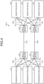
- Fig. 4 is a diagram of Exemplary illustration 2 in case of using the optical wavelength multiplexing technology.
- multiplexing devices 4a and 4b wavelength-multiplex the optical signals of the optical fibers 101a to 101c used for the quantum communication paths and multiplexing devices 4c and 4d wavelength-multiplex the optical signals of the optical fibers 102a to 102c used for the classical communication paths.
- wavelength-multiplex optical signals having the same intensity as in the QKD system 100-4 of Fig. 4 it is easier to wavelength-multiplex optical signals having the same intensity as in the QKD system 100-4 of Fig. 4 than to wavelength-multiplex optical signals having different intensities as in the QKD system 100-3 of Fig. 3 .
- the wavelength multiplexing method illustrated in Fig. 3 when the number of QKD devices used to improve the transmission speed of the encryption key is increased, the number of the required optical fibers 103 also increases in proportion to the number of QKD devices. Meanwhile, in the wavelength multiplexing method illustrated in Fig. 4 , even if the number of QKD devices that performs wavelength multiplexing increases, the number of required optical fibers remains two, and thus the mounting cost is suppressed.
- the wavelength multiplexing method illustrated in Fig. 4 when one optical fiber is disconnected, all the QKD devices do not operate. That is, when at least one optical fiber between the multiplexing devices is disconnected, the transmission of the encryption key by the QKD
- Fig. 5 is a diagram illustrating an example of a device configuration of a QKD system 200 according to a first arrangement.
- a QKD system 200 of the first arrangement includes transmission devices 1a to 1c, reception devices 2a to 2c, multiplexing devices 5a and 5b, and an electronic device 6. Note that the number of each of the transmission devices 1a to 1c and the reception devices 2a to 2c is not limited to three and may be any number.
- the multiplexing devices 5a and 5b are connected by three optical fibers 103a to 103c.
- the optical fibers 103a to 103c are simply referred to as the optical fibers 103.
- the multiplexing device 5a is installed on the transmission side and is connected to the quantum communication paths and the classical communication paths of the plurality of transmission devices 1a to 1c.
- the multiplexing device 5b is installed on the reception side and is connected to the quantum communication paths and the classical communication paths of the plurality of reception devices 2a to 2c.
- the multiplexing devices 5a and 5b wavelength-multiplex a plurality of quantum communication paths into one optical fiber 103 and a plurality of classical communication paths into one optical fiber 103.
- the multiplexing devices 5a and 5b are connected by three or more optical fibers 103 (the optical fibers 103a to 103c in the example of Fig. 5 ) and have a function of switching the optical fibers 103 to be used for performing encryption key transmission by the QKD. That is, the multiplexing devices 5a and 5b have a function of switching the optical fibers 103a to 103c to be used as the quantum communication path and the classical communication path in addition to the function of optical wavelength multiplexing.
- the multiplexing devices 5a and 5b switch the plurality of optical fibers 103a to 103c between the multiplexing devices 5a and 5b to determine the optical fiber 103 used as the quantum communication path and the optical fiber 103 used as the classical communication path.
- the number of optical fibers 103 between the multiplexing devices 5a and 5b is required to be more than two.
- the optical fiber 103a is used as a quantum communication path
- the optical fiber 103b is used as a classical communication path
- the optical fiber 103c is secured as a reserve.
- the electronic device 6 includes a monitoring unit 61 and a control unit 62.
- the monitoring unit 61 monitors transmission statuses of the encryption keys of the QKD devices (the transmission devices 1a to 1c and the reception devices 2a to 2c). For example, the monitoring unit 61 monitors the transmission statuses of the plurality of quantum signals flowing through the optical fiber 103a by receiving at least one of the encryption key generation speed based on the quantum signal and the error rate of the quantum signal from the plurality of reception devices 2a to 2c. For example, when the monitoring unit 61 detects the stop of transmission of the encryption key in each QKD device due to disconnection of the optical fiber 103a or the like, the monitoring unit notifies the control unit 62 of the stop of transmission of the encryption key.
- the control unit 62 switches the optical fibers 103 used by the multiplexing devices 5a and 5b according to the transmission status of the encryption key of each QKD device by the monitoring unit 61. For example, when receiving the notification of the stop of the transmission of the encryption key from the monitoring unit 61, the control unit 62 transmits an instruction to switch the optical fiber 103a used as the quantum communication path to the optical fiber 103c to the multiplexing devices 5a and 5b.
- the multiplexing devices 5a and 5b are simply referred to as the multiplexing devices 5.
- Fig. 6 is a diagram illustrating an example of a functional configuration of the multiplexing device 5 according to the first arrangement.
- the multiplexing device 5 of the first arrangement includes a multiplexing unit 51 and a switching control unit 52.
- the multiplexing unit 51 receives a plurality of quantum signals including encryption key information shared by the QKD and a plurality of classical signals including control information of the QKD from a plurality of QKD devices (transmission devices 1a to 1c). Then, the multiplexing unit 51 wavelength-multiplexes the plurality of quantum signals by using the optical fiber 103a (first optical fiber) selected from the plurality of optical fibers 103 and wavelength-multiplexes the plurality of quantum signals by using the optical fiber 103b (second optical fiber) selected from the plurality of optical fibers 103.
- the switching control unit 52 switches the optical fiber 103a (first optical fiber) or the optical fiber 103b (second optical fiber) to another optical fiber (the optical fiber 103c in the example of Fig. 5 ) selected from the plurality of optical fibers 103.
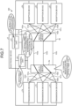
- Fig. 7 is a diagram illustrating an example the switching control of the optical fibers 103a to 103c according to the first arrangement. It is assumed that the quantum communication paths (the optical fibers 101a to 101c) of three QKD systems are multiplexed in the optical fiber 103a, the classical communication paths (the optical fibers 102a to 102c) are multiplexed in the optical fiber 103b, and the optical fiber 103c is unused.
- Step S1 It is assumed that the transmission of the encryption key cannot be continued because the optical fiber 103a is disconnected or eavesdropped for some reason (Step S1). Then, the monitoring unit 61 detects that the transmission status of the encryption key of each of the QKD devices (the transmission devices 1a to 1c and the reception devices 2a to 2c) are in the transmission stop state (Step S2) and notifies the control unit 62 of the detection result.
- the monitoring unit 61 may notify not only the transmission stop state of the encryption key but also the operation information of the QKD device relating to the detection result.
- the operation information of the QKD device is the number of photon detections, a quantum bit error rate (QBER), an encryption key transmission speed (otherwise, an encryption key sharing speed, or an encryption key generation speed), and the like.
- QBER quantum bit error rate
- the encryption key transmission speed there is a relationship in which the encryption key transmission speed decreases when the QBER increases.
- the control unit 62 issues, to at least one of the multiplexing devices 5a and 5b, an instruction to switch the quantum communication path not to the optical fiber 103a but to the unused optical fiber 103c (Step S3).
- Step S4 When receiving the instruction from the control unit 62, the switching control unit 52 of each of the multiplexing devices 5a and 5b switches the quantum communication path not to the optical fiber 103a but to the unused optical fiber 103c. As a result, transmission of the encryption key is continued (Step S4).
- control unit 62 can also issue the instruction to switch the classical communication path in the same manner as in the case of the quantum communication path described above, and the multiplexing devices 5a and 5b can also switch the classical communication path in the same manner as in the case of the quantum communication path described above.
- the transmission of the encryption key can be continued even when there is a defect in the optical fiber 103, and the redundancy is improved.
- the plurality of optical fibers 103 may be three or more and may include at least one unused optical fiber 103.
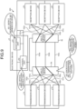
- Fig. 8 is a diagram illustrating an example of multiplexing control according to the first arrangement.
- the optical wavelength multiplexing on the quantum signals having the same optical intensity can suppress deterioration of an error rate (QBER) of the quantum signals and suppress deterioration of an encryption key transmission speed, but still the encryption key transmission speed due to optical wavelength multiplexing may be degraded.
- the degradation can be suppressed by reducing the number of times of optical wavelength multiplexing.
- the quantum communication paths (the optical fibers 101a to 101c) of three QKD systems are multiplexed in the optical fiber 103a
- the classical communication paths (the optical fibers 102a to 102c) are multiplexed in the optical fiber 103b
- the optical fiber 103c is unused.
- the monitoring unit 61 monitors the states (such as a transmission status and a status of use) of the optical fibers 103a to 103c and the transmission status of the encryption key (step S11).
- the control unit 62 When the transmission speed of the encryption key monitored by the monitoring unit 61 is in a normal state and there is the unused optical fiber 103 (the optical fiber 103c in the example of Fig. 8 ), the control unit 62 performs multiplexing control based on the operation state of each QKD device (the transmission devices 1a to 1c and the reception devices 2a to 2c) from the monitoring unit 61. Specifically, when the transmission statuses of the optical fibers 103a to 103c are normal, the control unit 62 issues, to at least one of the multiplexing devices 5a and 5b, an instruction to release a part of the plurality of quantum signals subjected to wavelength multiplexing and switch the transmission of the released quantum signals to the unused optical fiber 103. In the example of Fig.
- the control unit 62 issues, to at least one of the multiplexing devices 5a and 5b, an instruction to partially release the wavelength multiplexing of the optical fiber 103a, allocate the optical fiber 101c to the optical fiber 103c, and allocate the optical fibers 101a and 101b to the optical fiber 103a for wavelength multiplexing (Step S12).
- the multiplexing unit 51 of each of the multiplexing devices 5a and 5b switches the allocation of the quantum communication paths based on the instruction from the control unit 62 (Step S13).
- the number of times of optical wavelength multiplexing of the optical fiber 103a is reduced, and degradation of the encryption key transmission speed of the optical fibers 101a and 101b can be suppressed.
- the optical fiber 103c is used only for the optical fiber 101c and optical wavelength multiplexing is not performed in the optical fiber 101c, degradation of the encryption key transmission speed of the optical fiber 101c is also suppressed.
- the encryption key transmission speed of the QKD system 200 as a whole is improved.
- Fig. 9 is a diagram illustrating an example of the quality degradation investigation control according to the first arrangement. In the example of Fig. 9 , control in case of investigating the cause of performance degradation is described.
- the quantum communication paths (the optical fibers 101a to 101c) of three QKD systems are multiplexed in the optical fiber 103a
- the classical communication paths (the optical fibers 102a to 102c) are multiplexed in the optical fiber 103b
- the optical fiber 103c is unused.
- the monitoring unit 61 detects degradation of the encryption key generation speed (Step S21) and notifies the control unit 62 of a detection result indicating degradation of the encryption key generation speed. For example, when the encryption key generation speed is smaller than the generation threshold value, the monitoring unit 61 notifies the control unit 62 of a detection result indicating degradation of the encryption key generation speed. Note that, when the error rate of the quantum signal is larger than an error rate threshold, the monitoring unit 61 may notify the control unit 62 of a detection result indicating degradation of the error rate of the quantum signal.
- the control unit 62 issues, to at least one of the multiplexing devices 5a and 5b, an instruction to switch the optical fibers 103a to 103c (Step S22).
- the control unit 62 issues, to at least one of the multiplexing devices 5a and 5b, an instruction to switch between the quantum communication paths (the optical fibers 101a to 101c) wavelength-multiplexed into the optical fiber 103a and the classical communication paths (the optical fibers 102a to 102c) wavelength-multiplexed into the optical fiber 103b.
- the switching control units 52 of the multiplexing devices 5a and 5b switch the quantum communication paths (the optical fibers 101a to 101c) wavelength-multiplexed into the optical fiber 103a to the optical fiber 103b and switch the classical communication paths (the optical fibers 102a to 102c) wavelength-multiplexed into the optical fiber 103b to the optical fiber 103a (Step S23).
- the monitoring unit 61 receives the encryption key transmission speed measured after switching and compares the encryption key transmission speeds before and after switching (Step S24). If the encryption key transmission speed is improved, the monitoring unit 61 specifies quality degradation of the optical fiber 103 in which degradation of the encryption key generation speed is detected in Step S21.
- the plurality of transmission devices 1a to 1c transmit the plurality of quantum signals including the encryption key information shared by the QKD and the plurality of classical signals including the control information of the QKD.
- the plurality of reception devices 2a to 2c receive the plurality of quantum signals and the plurality of classical signals.
- the multiplexing device 5a first multiplexing device
- the multiplexing device 5b second multiplexing device
- the plurality of optical fibers 103a to 103c connect the first multiplexing device and the second multiplexing device.
- the electronic device 6 monitors the transmission statuses of the plurality of optical fibers 103a to 103c.
- the plurality of optical fibers 103 includes the optical fiber 103a (first optical fiber) in which quantum signals are wavelength-multiplexed and the optical fiber 103b (second optical fiber) in which classical signals are wavelength-multiplexed.
- the monitoring unit 61 monitors a transmission status of the plurality of quantum signals flowing through the first optical fiber and a transmission status of the plurality of classical signals flowing through the second optical fiber.
- the control unit 62 issues, to at least one of the first multiplexing device and the second multiplexing device, an instruction to switch the first optical fiber or the second optical fiber to another optical fiber selected from the plurality of optical fibers 103 according to the monitoring result (the receiving result) of the monitoring unit 61.
- Fig. 10 is a diagram illustrating an example of synchronization parameter initialization control according to the second arrangement.
- the optical fiber 103 used between the multiplexing devices 5a and 5b is switched, if characteristics such as the length of the optical fiber 103 are changed before and after switching, initialization of a synchronization parameter used for synchronization of transmission and reception between the transmission device 1 and the reception device 2 may be required.
- the length of the optical fiber 103c is longer than the length of the optical fiber 103a.
- the control unit 62 issues, for example, an instruction to initialize the synchronization parameters to the transmission devices 1a to 1c (Step S32).
- Step S32 may be issued to the reception devices 2a to 2c or may be issued to both the transmission devices 1a to 1c and the reception devices 2a to 2c.
- the control unit 62 issues an instruction to initialize the synchronization parameter used for synchronization of transmission and reception between the plurality of transmission devices 1a to 1c and the plurality of reception devices 2a to 2c to at least one of the plurality of transmission devices 1a to 1c and the plurality of reception devices 2a to 2c.
- the transmission devices 1a to 1c are required to be designed and manufactured in advance such that the wavelengths of the signals thereof are different from each other.
- a plurality of quantum signal light sources that generates quantum signals having different wavelengths and a plurality of classical signal light sources that generates classical signals having different wavelengths are mounted.
- a control method for switching the wavelength of the light source according to the transmission devices 1a to 1c to be combined in multiplexing is described.
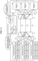
- Fig. 11 is a diagram illustrating an example of light source wavelength switching control according to the third arrangement.
- the multiplexing devices 5a and 5b perform optical wavelength multiplexing on the quantum communication paths and the classical communication paths of the QKD devices (the transmission devices 1a to 1c and the reception devices 2a to 2c)
- the transmission device 1a of the third arrangement can generate three kinds of quantum signals (quanta 1-1 to 1-3) having different wavelengths and three kinds of classical signals (classics 1-1 to 1-3) having different wavelengths.
- the transmission device 1b can generate three kinds of quantum signals (quanta 2-1 to 2-3) having different wavelengths and three kinds of classical signals (classics 2-1 to 2-3) having different wavelengths.
- the transmission device 1c can generate three kinds of quantum signals (quanta 3-1 to 3-3) having different wavelengths and three kinds of classical signals (classics 3-1 to 3-3) having different wavelengths.
- the monitoring unit 61 collects the wavelength information of the light source of the quantum signal and the wavelength information of the light source of the classical signal from each of the transmission devices 1a to 1c (Step S41) .
- Step S42 Based on the wavelength information collected in Step S41, the control unit 62 instructs each of the transmission devices 1a to 1c to use a light source having some wavelength (Step S42).
- Each of the transmission devices 1a to 1c selects quantum signal light source respectively different in the transmission devices 1a to 1c and classical signal light sources respectively different in the transmission devices 1a to 1c based on the instruction in Step S42 and starts encryption key transmission by using the selected light source.
- the control unit 62 instructs the transmission devices 1a to 1c such that the wavelengths of the quantum signals of the transmission devices 1a to 1c are different from each other, and the wavelengths of the classical signals are different from each other.
- the control unit 62 instructs the transmission devices 1a to 1c such that the wavelengths of the quantum signals of the transmission devices 1a to 1c are different from each other, and the wavelengths of the classical signals are different from each other.
- the control unit 62 instructs the transmission devices 1a to 1c such that the wavelengths of the quantum signals of the transmission devices 1a to 1c are different from each other, and the wavelengths of the classical signals are different from each other.
- the control unit 62 instructs the transmission devices 1a to 1c such that the wavelengths of the quantum signals of the transmission devices 1a to 1c are different from each other, and the wavelengths of the classical signals are different from each other.
- the multiplexing devices 5a and 5b can perform wavelength multiplexing without any problem.
- Fig. 12 is a diagram illustrating an example of hardware configurations of the multiplexing device 5 and the electronic device 6 according to the first to third arrangements.
- the multiplexing device 5 and the electronic device 6 of the first to third arrangements include a processor 201, a main storage device 202, an auxiliary storage device 203, a display device 204, an input device 205, and a communication device 206.
- the processor 201, the main storage device 202, the auxiliary storage device 203, the display device 204, the input device 205, and the communication device 206 are connected to each other via a bus 210.
- the multiplexing device 5 and the electronic device 6 may not include a part of the above configurations.
- the display device 204 and the input device 205 may not be provided in the multiplexing device 5 and the electronic device 6.
- the processor 201 executes a program read from the auxiliary storage device 203 to the main storage device 202.
- the main storage device 202 is a memory such as a ROM and a RAM.
- the auxiliary storage device 203 is a hard disk drive (HDD), a memory card, or the like.
- the display device 204 is, for example, a liquid crystal display.
- the input device 205 is an interface for operating the multiplexing device 5 and the electronic device 6. Note that the display device 204 and the input device 205 may be embodied by a touch panel or the like having a display function and an input function.
- the communication device 206 is an interface for communicating with other devices.
- the program executed by the multiplexing device 5 and the electronic device 6 is a file in an installable format or an executable format, is recorded in a computer-readable storage medium such as a memory card, a hard disk, a CD-RW, a CD-ROM, a CD-R, a DVD-RAM, and a DVD-R, and is provided as a computer program product.
- a computer-readable storage medium such as a memory card, a hard disk, a CD-RW, a CD-ROM, a CD-R, a DVD-RAM, and a DVD-R
- programs to be executed by the multiplexing device 5 and the electronic device 6 may be configured to be stored on a computer connected to a network such as the Internet and be provided by being downloaded via the network.
- the program executed by the multiplexing device 5 and the electronic device 6 may be configured to be provided via a network such as the Internet without being downloaded.
- the control processing of the multiplexing device 5 and the control processing of the electronic device 6 may be configured to be executed by an application service provider (ASP) type cloud service.
- ASP application service provider
- the programs of the multiplexing device 5 and the electronic device 6 may be configured to be provided by being incorporated in a ROM or the like in advance.
- the program executed by the multiplexing device 5 and the electronic device 6 has a module configuration including functions that can be embodied by the program among the functional configurations described above.
- the processor 201 reads a program from a storage medium and executes the program, and the functional blocks are loaded on the main storage device 202. That is, the functional blocks are generated on the main storage device 202.
- each function may be embodied by using the plurality of processors 201, and in this case, each processor 201 may embody one of the functions or may embody two or more of the functions.
- a QKD system (100) includes a plurality of transmission devices (1a, 1b, 1c), a plurality of reception devices (2a, 2b, 2c), a first multiplexing device (5a), a second multiplexing device (5b), a plurality of optical fibers (103a, 103b, 103c), and an electronic device (6).
- the transmission devices (1a, 1b, 1c) are configured to transmit a plurality of quantum signals including encryption key information shared by quantum key distribution (QKD) and a plurality of classical signals including control information of the QKD.
- the reception devices (2a, 2b, 2c) are configured to receive the plurality of quantum signals and the plurality of classical signals.
- the first multiplexing device (5a) is configured to be connected to the plurality of transmission devices (1a, 1b, 1c).
- the second multiplexing device (5b) is configured to be connected to the plurality of reception devices (2a, 2b, 2c).
- the optical fibers (103a, 103b, 103c) are configured to connect the first multiplexing device (5a) and the second multiplexing device (5b).
- the electronic device (6) is configured to receive transmission statuses of the plurality of optical fibers (103a, 103b, 103c).
- the optical fibers (103a, 103b, 103c) include a first optical fiber in which the plurality of quantum signals is wavelength-multiplexed and a second optical fiber in which the plurality of classical signals is wavelength-multiplexed.
- the electronic device (6) is configured to receive transmission statuses of the plurality of quantum signals flowing through the first optical fiber and transmission statuses of the plurality of classical signals flowing through the second optical fiber.
- the electronic device (6) is configured to issue, to at least one of the first multiplexing device (5a) and the second multiplexing device (5b), an instruction to switch the first optical fiber or the second optical fiber to another optical fiber selected from the plurality of optical fibers (103a, 103b, 103c) according to a receiving result.
- the plurality of optical fibers (103a, 103b, 103c) includes three or more optical fibers (103a, 103b, 103c) and at least one unused optical fiber
- the electronic device (6) issues, to at least one of the first multiplexing device (5a) and the second multiplexing device (5b), an instruction to switch the first optical fiber or the second optical fiber to the unused optical fiber selected from the plurality of optical fibers (103a, 103b, 103c) according to the receiving result.
- Example 3 In the QKD system (100) according to example 2, the electronic device (6) receives the transmission statuses of the plurality of quantum signals flowing through the first optical fiber by receiving at least one of an encryption key generation speed based on a quantum signal and an error rate of a quantum signal from the plurality of reception devices (2a, 2b, 2c).
- Example 4 In the QKD system (100) according to example 3, when at least one of the encryption key generation speed being smaller than a generation threshold, or the error rate of the quantum signal being larger than an error rate threshold is detected, the electronic device (6) issues, to at least one of the first multiplexing device (5a) and the second multiplexing device (5b), an instruction to switch the first optical fiber to the second optical fiber.
- the electronic device (6) specifies quality degradation of the first optical fiber when the encryption key generation speed is improved after switching between the first optical fiber and the second optical fiber.
- Example 5 In the QKD system (100) according to any one of examples 2 to 4, when the transmission statuses of the plurality of optical fibers (103a, 103b, 103c) are normal, the electronic device (6) issues, to at least one of the first multiplexing device (5a) and the second multiplexing device (5b), an instruction to release a part of the plurality of quantum signals wavelength-multiplexed in the first optical fiber and switch transmission of the released quantum signals to the unused optical fiber.
- Example 6 In the QKD system (100) according to any one of examples 1 to 4, the electronic device (6) issues, to at least one of the first multiplexing device (5a) and the second multiplexing device (5b), an instruction to switch the first optical fiber to another optical fiber selected from the plurality of optical fibers (103a, 103b, 103c) when transmission of the plurality of quantum signals flowing through the first optical fiber is stopped.
- Example 7 In the QKD system (100) according to any one of examples 1 to 4, when a characteristic of the optical fiber before switching is different from a characteristic of the optical fiber after switching, the electronic device (6) issues, to at least one of the plurality of transmission devices (1a, 1b, 1c) and the plurality of reception devices (2a, 2b, 2c), an instruction to initialize a synchronization parameter used for synchronization of transmission and reception between the plurality of transmission devices (1a, 1b, 1c) and the plurality of reception devices (2a, 2b, 2c).
- the plurality of transmission devices (1a, 1b, 1c) includes a plurality of quantum signal light sources configured to generate quantum signals having different wavelengths, and a plurality of classical signal light sources configured to generate classical signals having different wavelengths.
- the electronic device (6) issues, to the plurality of transmission devices (1a, 1b, 1c), an instruction to use the quantum signal light source such that wavelengths of a plurality of quantum signals waveform-multiplexed in the first optical fiber are different from each other and issues, to the plurality of transmission devices (1a, 1b, 1c), an instruction to use the classical signal light source such that wavelengths of a plurality of classical signals waveform-multiplexed in the second optical fiber are different from each other.
- An electronic device (6) is configured to receive transmission statuses of a plurality of optical fibers (103a, 103b, 103c) that connect a first multiplexing device (5a) connected to the plurality of transmission devices (1a, 1b, 1c) and a second multiplexing device (5b) connected to the plurality of reception devices (2a, 2b, 2c).
- the optical fibers (103a, 103b, 103c) include a first optical fiber in which a plurality of quantum signals including encryption key information shared by quantum key distribution (QKD) is wavelength-multiplexed and a second optical fiber in which a plurality of classical signals including control information of the QKD is wavelength-multiplexed.
- QKD quantum key distribution
- the electronic device (6) is configured to receive transmission statuses of the plurality of quantum signals flowing through the first optical fiber and transmission statuses of the plurality of classical signals flowing through the second optical fiber, and issue, to at least one of the first multiplexing device (5a) and the second multiplexing device (5b), an instruction to switch the first optical fiber or the second optical fiber to another optical fiber selected from the plurality of optical fibers (103a, 103b, 103c) according to a receiving result.
- Example 10 A multiplexing device (5) according to an arrangement is connected to an opposed multiplexing device (5) by a plurality of optical fibers (103a, 103b, 103c).
- the multiplexing device includes a multiplexing unit (51) and a switching control unit (52).
- the multiplexing unit (51) is configured to, when receiving a plurality of quantum signals including encryption key information shared by quantum key distribution (QKD) and a plurality of classical signals including control information of the QKD from a plurality of QKD devices, wavelength-multiplex the plurality of quantum signals by using a first optical fiber selected from the plurality of optical fibers (103a, 103b, 103c) and wavelength-multiplex the plurality of quantum signals by using a second optical fiber selected from the plurality of optical fibers (103a, 103b, 103c).
- the switching control unit (52) is configured to switch the first optical fiber or the second optical fiber to another optical fiber selected from the plurality of optical fibers (103a, 103b, 103c) according to a switching instruction from an electronic device (6).
- Example 11 A method according to an arrangement is implemented by an electronic device (6).
- the electronic device (6) is configured to receive transmission statuses of optical fibers (103a, 103b, 103c) that connect a first multiplexing apparatus (5a) connected to a plurality of transmitters (1a, 1b, 1c) and a second multiplexing apparatus (5b) connected to a plurality of receivers (2a, 2b, 2c).
- the optical fibers (103a, 103b, 103c) include a first optical fiber in which a plurality of quantum signals including encryption key information shared by quantum key distribution (QKD) is wavelength-multiplexed and a second optical fiber in which a plurality of classical signals including control information of the QKD is wavelength-multiplexed.
- QKD quantum key distribution
- the method includes receiving transmission statuses of the plurality of quantum signals flowing through the first optical fiber and transmission statuses of the plurality of classical signals flowing through the second optical fiber; and issuing, to at least one of the first multiplexing apparatus (5a) and the second multiplexing apparatus (5b), an instruction to switch the first optical fiber or the second optical fiber to another optical fiber selected from the plurality of optical fibers (103a, 103b, 103c) according to a receiving result.
- Example 12 A computer program product according to an arrangement has a computer readable medium including programmed instructions stored thereon.
- the programmed instructions are for operating an electronic device (6) configured to receive transmission statuses of a plurality of optical fibers (103a, 103b, 103c) that connect a first multiplexing device (5a) connected to a plurality of transmission devices (1a, 1b, 1c) and a second multiplexing device (5b) connected to a plurality of reception devices (2a, 2b, 2c).
- the optical fibers (103a, 103b, 103c) include a first optical fiber in which a plurality of quantum signals including encryption key information shared by quantum key distribution (QKD) is wavelength-multiplexed and a second optical fiber in which a plurality of classical signals including control information of the QKD is wavelength-multiplexed.
- QKD quantum key distribution
- the instructions when executed by a computer, cause the computer to receive transmission statuses of the plurality of quantum signals flowing through the first optical fiber and transmission statuses of the plurality of classical signals flowing through the second optical fiber, and issue, to at least one of the first multiplexing device (5a) and the second multiplexing device (5b), an instruction to switch the first optical fiber or the second optical fiber to another optical fiber selected from the plurality of optical fibers (103a, 103b, 103c) according to a receiving result.
Landscapes
- Engineering & Computer Science (AREA)
- Physics & Mathematics (AREA)
- Theoretical Computer Science (AREA)
- Signal Processing (AREA)
- Computer Networks & Wireless Communication (AREA)
- Electromagnetism (AREA)
- Computer Security & Cryptography (AREA)
- General Physics & Mathematics (AREA)
- Data Mining & Analysis (AREA)
- Mathematical Analysis (AREA)
- Pure & Applied Mathematics (AREA)
- Computing Systems (AREA)
- General Engineering & Computer Science (AREA)
- Mathematical Physics (AREA)
- Software Systems (AREA)
- Mathematical Optimization (AREA)
- Evolutionary Computation (AREA)
- Condensed Matter Physics & Semiconductors (AREA)
- Computational Mathematics (AREA)
- Artificial Intelligence (AREA)
- Optics & Photonics (AREA)
- Optical Communication System (AREA)
Abstract
According to one arrangement, a QKD system includes transmission devices configured to transmit quantum signals and classical signals. An electronic device receives transmission statuses of optical fibers. The optical fibers includes a first optical fiber in which the quantum signals are wavelength-multiplexed and a second optical fiber in which the classical signals are wavelength-multiplexed. The electronic device receives a transmission status of the quantum signals flowing through the first optical fiber and a transmission status of the classical signals flowing through the second optical fiber, and issues, to at least one of a first multiplexing device and the second multiplexing device, an instruction to switch the first optical fiber or the second optical fiber to another optical fiber selected from the optical fibers according to a receiving result.
Description
- Arrangements described herein relate generally to a QKD system, an electronic device, a multiplexing device, and a computer program product.
- A quantum key distribution technology (Quantum Key Distribution, hereinafter referred to as QKD) is a technology by which an encryption key is securely shared between a transmission device that continuously transmits a single photon and a reception device that receives the single photon, which are connected by an optical fiber. An encryption key shared by QKD is guaranteed not to be eavesdropped based on the principle of quantum mechanics. It is guaranteed by information theory that data that is subjected to encrypted data communication using a cryptographic communication method called a one-time pad using a shared encryption key cannot be decrypted by an eavesdropper having any knowledge.
- However, in the related art, it is difficult to continue transmission of an encryption key even when a defect such as disconnection occurs in an optical fiber while improving the transmission speed of the encryption key by optical wavelength multiplexing with a limited number of optical fibers.
-
-
Fig. 1 is a diagram illustrating an exemplary configuration of one general QKD system; -
Fig. 2 is a diagram illustrating an exemplary configuration of a QKD system using a plurality of QKD devices; -
Fig. 3 is a diagram ofExemplary illustration 1 in case of using an optical wavelength multiplexing technology; -
Fig. 4 is a diagram ofExemplary illustration 2 in case of using an optical wavelength multiplexing technology; -
Fig. 5 is a diagram illustrating an example of a device configuration of a QKD system according to a first arrangement; -
Fig. 6 is a diagram illustrating an example of a functional configuration of a multiplexing device according to the first arrangement; -
Fig. 7 is a diagram illustrating an example of optical fiber switching control according to the first arrangement; -
Fig. 8 is a diagram illustrating an example of multiplexing control according to the first arrangement; -
Fig. 9 is a diagram illustrating an example of quality degradation investigation control according to the first arrangement; -
Fig. 10 is a diagram illustrating an example of synchronization parameter initialization control according to a second arrangement; -
Fig. 11 is a diagram illustrating an example of light source wavelength switching control according to a third arrangement; and -
Fig. 12 is a diagram illustrating an example of a hardware configuration of a multiplexing device and an electronic device according to the first to third arrangements. - Hereinafter, arrangements of a QKD system, an electronic device, a multiplexing device, and a computer program product are described in detail with reference to the accompanying drawings.
- Hereinafter, an encryption key exchanging device using a quantum key distribution (QKD) technology is referred to as a QKD device. An encryption key exchange system configured with a plurality of QKD devices is referred to as a QKD system. First, an example of a general QKD system is described.
-
Fig. 1 is a diagram illustrating an exemplary configuration of one general QKD system. Ageneral QKD system 100 includes atransmission device 1, areception device 2, and twooptical fibers - The
transmission device 1 is a QKD device on a transmission side. Thetransmission device 1 generates a photon, encodes encryption key information indicating bit information of 0 or 1 in the photon, and transmits the photon in which the encryption key information is encoded to thereception device 2. - The
reception device 2 is a QKD device on a reception side. Thereception device 2 receives the photon transmitted from thetransmission device 1 and decodes the encryption key information. - The
optical fiber 101 is used as a quantum communication path for transmitting a quantum signal encoded with encryption key information. - The
optical fiber 102 is used as a classical communication path for transmitting a classical signal including QKD control information. For example, the classical communication path is used for transmission of a synchronization signal between a transmitter of the photon used in thetransmission device 1 and a receiver of photons used in thereception device 2 and an optical signal such as data communication. - Since the quantum signal in the quantum communication path is extremely weaker than the optical signal in the classical communication path, the
optical fibers optical fiber 101 of the quantum communication path and theoptical fiber 102 of the classical communication path need to be dark fibers. -
Fig. 2 is a diagram illustrating an exemplary configuration of a QKD system 100-2 including a plurality of QKD devices. In the QKD system 100-2, the number of QKD devices is increased in order to improve the transmission speed of a shared encryption key, and thus the transmission speed of the encryption key in the entire QKD system 100-2 is improved. As illustrated inFig. 2 , for example, the transmission speed of the encryption key when three QKD systems are used is 3 times faster than that when one QKD system 100 (Fig. 1 ) is used. However, in this case, the number of optical fibers required increases. It is not practical to increase the number of optical fibers required for socially implementing a QKD system. - Therefore, there is a method of embodying a quantum communication path and a classical communication path with one optical fiber by using an optical wavelength multiplexing technology (
JP 4784202 B2 -
Fig. 3 is a diagram ofExemplary illustration 1 in case of using the optical wavelength multiplexing technology. In a QKD system 100-3 ofFig. 3 ,multiplexing devices 3a and 3b that wavelength-multiplex optical signals and anoptical fiber 103 are used in addition to a normal QKD device (thetransmission device 1 and the reception device 2), anoptical fiber 101 used as the quantum communication path, and anoptical fiber 102 used as the classical communication path. - The
transmission device 1 and themultiplexing device 3a, and thereception device 2 and the multiplexing device 3b are arranged in, for example, the same rack and connected by a short optical fiber. Themultiplexing devices 3a and 3b are connected by anoptical fiber 103 corresponding to a communication distance similarly to the normal QKD device. - However, in
Exemplary illustration 1 ofFig. 3 , it is required to wavelength-multiplex optical signals having different intensities, which is technically difficult. Therefore, as illustrated inFig. 4 , a method of wavelength-multiplexingoptical fibers 101a to 101c of the quantum communication path into oneoptical fiber 101d and wavelength-multiplexingoptical fibers 102a to 102c of the classical communication path into oneoptical fiber 102d is also considered. -
Fig. 4 is a diagram ofExemplary illustration 2 in case of using the optical wavelength multiplexing technology. In a QKD system 100-4 ofFig. 4 ,multiplexing devices 4a and 4b wavelength-multiplex the optical signals of theoptical fibers 101a to 101c used for the quantum communication paths andmultiplexing devices 4c and 4d wavelength-multiplex the optical signals of theoptical fibers 102a to 102c used for the classical communication paths. - It is easier to wavelength-multiplex optical signals having the same intensity as in the QKD system 100-4 of
Fig. 4 than to wavelength-multiplex optical signals having different intensities as in the QKD system 100-3 ofFig. 3 . In the wavelength multiplexing method illustrated inFig. 3 , when the number of QKD devices used to improve the transmission speed of the encryption key is increased, the number of the requiredoptical fibers 103 also increases in proportion to the number of QKD devices. Meanwhile, in the wavelength multiplexing method illustrated inFig. 4 , even if the number of QKD devices that performs wavelength multiplexing increases, the number of required optical fibers remains two, and thus the mounting cost is suppressed. As a disadvantage of the wavelength multiplexing method illustrated inFig. 4 , when one optical fiber is disconnected, all the QKD devices do not operate. That is, when at least one optical fiber between the multiplexing devices is disconnected, the transmission of the encryption key by the QKD devices is stopped. - Hereinafter, an arrangement of a QKD system capable of continuing transmission of an encryption key even when a defect such as disconnection occurs in an optical fiber while improving a transmission speed of an encryption key by optical wavelength multiplexing with a limited number of optical fibers is described.
-
Fig. 5 is a diagram illustrating an example of a device configuration of aQKD system 200 according to a first arrangement. AQKD system 200 of the first arrangement includestransmission devices 1a to 1c,reception devices 2a to 2c,multiplexing devices electronic device 6. Note that the number of each of thetransmission devices 1a to 1c and thereception devices 2a to 2c is not limited to three and may be any number. Themultiplexing devices optical fibers 103a to 103c. Hereinafter, when theoptical fibers 103a to 103c are not distinguished, theoptical fibers 103a to 103c are simply referred to as theoptical fibers 103. - The
multiplexing device 5a is installed on the transmission side and is connected to the quantum communication paths and the classical communication paths of the plurality oftransmission devices 1a to 1c. Themultiplexing device 5b is installed on the reception side and is connected to the quantum communication paths and the classical communication paths of the plurality ofreception devices 2a to 2c. Themultiplexing devices optical fiber 103 and a plurality of classical communication paths into oneoptical fiber 103. - The
multiplexing devices optical fibers 103a to 103c in the example ofFig. 5 ) and have a function of switching theoptical fibers 103 to be used for performing encryption key transmission by the QKD. That is, themultiplexing devices optical fibers 103a to 103c to be used as the quantum communication path and the classical communication path in addition to the function of optical wavelength multiplexing. Themultiplexing devices optical fibers 103a to 103c between the multiplexingdevices optical fiber 103 used as the quantum communication path and theoptical fiber 103 used as the classical communication path. - Normally, when an encryption key is transmitted by the QKD by using two
optical fibers 103 and theoptical fiber 103 unused is also secured as a reserve, the number ofoptical fibers 103 between the multiplexingdevices Fig. 5 , theoptical fiber 103a is used as a quantum communication path, theoptical fiber 103b is used as a classical communication path, and theoptical fiber 103c is secured as a reserve. - The
electronic device 6 includes amonitoring unit 61 and acontrol unit 62. - The
monitoring unit 61 monitors transmission statuses of the encryption keys of the QKD devices (thetransmission devices 1a to 1c and thereception devices 2a to 2c). For example, themonitoring unit 61 monitors the transmission statuses of the plurality of quantum signals flowing through theoptical fiber 103a by receiving at least one of the encryption key generation speed based on the quantum signal and the error rate of the quantum signal from the plurality ofreception devices 2a to 2c. For example, when themonitoring unit 61 detects the stop of transmission of the encryption key in each QKD device due to disconnection of theoptical fiber 103a or the like, the monitoring unit notifies thecontrol unit 62 of the stop of transmission of the encryption key. - The
control unit 62 switches theoptical fibers 103 used by themultiplexing devices monitoring unit 61. For example, when receiving the notification of the stop of the transmission of the encryption key from themonitoring unit 61, thecontrol unit 62 transmits an instruction to switch theoptical fiber 103a used as the quantum communication path to theoptical fiber 103c to themultiplexing devices - Note that, in the example of
Fig. 5 , the configuration when the three QKD systems are subjected to the optical wavelength multiplexing is illustrated, but the number of QKD systems to be multiplexed may be two or more. - Hereinafter, when the
multiplexing devices multiplexing devices multiplexing devices 5. -
Fig. 6 is a diagram illustrating an example of a functional configuration of themultiplexing device 5 according to the first arrangement. Themultiplexing device 5 of the first arrangement includes a multiplexingunit 51 and aswitching control unit 52. - The multiplexing
unit 51 receives a plurality of quantum signals including encryption key information shared by the QKD and a plurality of classical signals including control information of the QKD from a plurality of QKD devices (transmission devices 1a to 1c). Then, the multiplexingunit 51 wavelength-multiplexes the plurality of quantum signals by using theoptical fiber 103a (first optical fiber) selected from the plurality ofoptical fibers 103 and wavelength-multiplexes the plurality of quantum signals by using theoptical fiber 103b (second optical fiber) selected from the plurality ofoptical fibers 103. - In response to the switching instruction from the
electronic device 6, the switchingcontrol unit 52 switches theoptical fiber 103a (first optical fiber) or theoptical fiber 103b (second optical fiber) to another optical fiber (theoptical fiber 103c in the example ofFig. 5 ) selected from the plurality ofoptical fibers 103. -
Fig. 7 is a diagram illustrating an example the switching control of theoptical fibers 103a to 103c according to the first arrangement. It is assumed that the quantum communication paths (theoptical fibers 101a to 101c) of three QKD systems are multiplexed in theoptical fiber 103a, the classical communication paths (theoptical fibers 102a to 102c) are multiplexed in theoptical fiber 103b, and theoptical fiber 103c is unused. - It is assumed that the transmission of the encryption key cannot be continued because the
optical fiber 103a is disconnected or eavesdropped for some reason (Step S1). Then, themonitoring unit 61 detects that the transmission status of the encryption key of each of the QKD devices (thetransmission devices 1a to 1c and thereception devices 2a to 2c) are in the transmission stop state (Step S2) and notifies thecontrol unit 62 of the detection result. - At this time, the
monitoring unit 61 may notify not only the transmission stop state of the encryption key but also the operation information of the QKD device relating to the detection result. For example, the operation information of the QKD device is the number of photon detections, a quantum bit error rate (QBER), an encryption key transmission speed (otherwise, an encryption key sharing speed, or an encryption key generation speed), and the like. As a relationship between the QBER (the error rate of the quantum signal) and the encryption key transmission speed, there is a relationship in which the encryption key transmission speed decreases when the QBER increases. - Based on the notification from the
monitoring unit 61, thecontrol unit 62 issues, to at least one of themultiplexing devices optical fiber 103a but to the unusedoptical fiber 103c (Step S3). - When receiving the instruction from the
control unit 62, the switchingcontrol unit 52 of each of themultiplexing devices optical fiber 103a but to the unusedoptical fiber 103c. As a result, transmission of the encryption key is continued (Step S4). - Note that the
control unit 62 can also issue the instruction to switch the classical communication path in the same manner as in the case of the quantum communication path described above, and themultiplexing devices - According to the switching control of the
optical fiber 103 illustrated inFig. 7 , the transmission of the encryption key can be continued even when there is a defect in theoptical fiber 103, and the redundancy is improved. Note that the plurality ofoptical fibers 103 may be three or more and may include at least one unusedoptical fiber 103. -
Fig. 8 is a diagram illustrating an example of multiplexing control according to the first arrangement. The optical wavelength multiplexing on the quantum signals having the same optical intensity, can suppress deterioration of an error rate (QBER) of the quantum signals and suppress deterioration of an encryption key transmission speed, but still the encryption key transmission speed due to optical wavelength multiplexing may be degraded. The degradation can be suppressed by reducing the number of times of optical wavelength multiplexing. - It is assumed that the quantum communication paths (the
optical fibers 101a to 101c) of three QKD systems are multiplexed in theoptical fiber 103a, the classical communication paths (theoptical fibers 102a to 102c) are multiplexed in theoptical fiber 103b, and theoptical fiber 103c is unused. - The
monitoring unit 61 monitors the states (such as a transmission status and a status of use) of theoptical fibers 103a to 103c and the transmission status of the encryption key (step S11). - When the transmission speed of the encryption key monitored by the
monitoring unit 61 is in a normal state and there is the unused optical fiber 103 (theoptical fiber 103c in the example ofFig. 8 ), thecontrol unit 62 performs multiplexing control based on the operation state of each QKD device (thetransmission devices 1a to 1c and thereception devices 2a to 2c) from themonitoring unit 61. Specifically, when the transmission statuses of theoptical fibers 103a to 103c are normal, thecontrol unit 62 issues, to at least one of themultiplexing devices optical fiber 103. In the example ofFig. 8 , thecontrol unit 62 issues, to at least one of themultiplexing devices optical fiber 103a, allocate theoptical fiber 101c to theoptical fiber 103c, and allocate theoptical fibers optical fiber 103a for wavelength multiplexing (Step S12). - The multiplexing
unit 51 of each of themultiplexing devices optical fiber 103a is reduced, and degradation of the encryption key transmission speed of theoptical fibers optical fiber 103c is used only for theoptical fiber 101c and optical wavelength multiplexing is not performed in theoptical fiber 101c, degradation of the encryption key transmission speed of theoptical fiber 101c is also suppressed. By releasing a part of the optical wavelength multiplexing in this manner, the encryption key transmission speed of theQKD system 200 as a whole is improved. -
Fig. 9 is a diagram illustrating an example of the quality degradation investigation control according to the first arrangement. In the example ofFig. 9 , control in case of investigating the cause of performance degradation is described. - It is assumed that the quantum communication paths (the
optical fibers 101a to 101c) of three QKD systems are multiplexed in theoptical fiber 103a, the classical communication paths (theoptical fibers 102a to 102c) are multiplexed in theoptical fiber 103b, and theoptical fiber 103c is unused. - First, the
monitoring unit 61 detects degradation of the encryption key generation speed (Step S21) and notifies thecontrol unit 62 of a detection result indicating degradation of the encryption key generation speed. For example, when the encryption key generation speed is smaller than the generation threshold value, themonitoring unit 61 notifies thecontrol unit 62 of a detection result indicating degradation of the encryption key generation speed. Note that, when the error rate of the quantum signal is larger than an error rate threshold, themonitoring unit 61 may notify thecontrol unit 62 of a detection result indicating degradation of the error rate of the quantum signal. - When receiving the notification from the
monitoring unit 61, thecontrol unit 62 issues, to at least one of themultiplexing devices optical fibers 103a to 103c (Step S22). For example, thecontrol unit 62 issues, to at least one of themultiplexing devices optical fibers 101a to 101c) wavelength-multiplexed into theoptical fiber 103a and the classical communication paths (theoptical fibers 102a to 102c) wavelength-multiplexed into theoptical fiber 103b. - In accordance with the instruction from the
control unit 62, the switchingcontrol units 52 of themultiplexing devices optical fibers 101a to 101c) wavelength-multiplexed into theoptical fiber 103a to theoptical fiber 103b and switch the classical communication paths (theoptical fibers 102a to 102c) wavelength-multiplexed into theoptical fiber 103b to theoptical fiber 103a (Step S23). - The
monitoring unit 61 receives the encryption key transmission speed measured after switching and compares the encryption key transmission speeds before and after switching (Step S24). If the encryption key transmission speed is improved, themonitoring unit 61 specifies quality degradation of theoptical fiber 103 in which degradation of the encryption key generation speed is detected in Step S21. - As described above, in the
QKD system 200 according to the first arrangement, the plurality oftransmission devices 1a to 1c transmit the plurality of quantum signals including the encryption key information shared by the QKD and the plurality of classical signals including the control information of the QKD. The plurality ofreception devices 2a to 2c receive the plurality of quantum signals and the plurality of classical signals. Themultiplexing device 5a (first multiplexing device) is connected to the plurality oftransmission devices 1a to 1c. Themultiplexing device 5b (second multiplexing device) is connected to the plurality of reception devices (2a to 2c). The plurality ofoptical fibers 103a to 103c connect the first multiplexing device and the second multiplexing device. Theelectronic device 6 monitors the transmission statuses of the plurality ofoptical fibers 103a to 103c. The plurality ofoptical fibers 103 includes theoptical fiber 103a (first optical fiber) in which quantum signals are wavelength-multiplexed and theoptical fiber 103b (second optical fiber) in which classical signals are wavelength-multiplexed. Themonitoring unit 61 monitors a transmission status of the plurality of quantum signals flowing through the first optical fiber and a transmission status of the plurality of classical signals flowing through the second optical fiber. Thecontrol unit 62 issues, to at least one of the first multiplexing device and the second multiplexing device, an instruction to switch the first optical fiber or the second optical fiber to another optical fiber selected from the plurality ofoptical fibers 103 according to the monitoring result (the receiving result) of themonitoring unit 61. - As a result, with the
QKD system 200 according to the first arrangement, it is possible to continue the transmission of the encryption key even when a defect such as disconnection occurs in theoptical fiber 103 while improving the transmission speed of the encryption key by the optical wavelength multiplexing with a limited number ofoptical fibers 103. - Next, a second arrangement is described. In the description of the second arrangement, the description similar to that of the first arrangement is omitted, and parts different from those of the first arrangement are described. In the second arrangement, an example in which the
electronic device 6 performs synchronization parameter initialization control is described. -
Fig. 10 is a diagram illustrating an example of synchronization parameter initialization control according to the second arrangement. When theoptical fiber 103 used between the multiplexingdevices optical fiber 103 are changed before and after switching, initialization of a synchronization parameter used for synchronization of transmission and reception between thetransmission device 1 and thereception device 2 may be required. - In the example of
Fig. 10 , the length of theoptical fiber 103c is longer than the length of theoptical fiber 103a. For example, it is assumed that theoptical fiber 103a used for multiplexing the quantum communication paths (theoptical fibers 101a to 101c) is switched to the unusedoptical fiber 103c by the switching control described with reference toFig. 7 (Step S31). In such a case, thecontrol unit 62 issues, for example, an instruction to initialize the synchronization parameters to thetransmission devices 1a to 1c (Step S32). - Note that the instruction in Step S32 may be issued to the
reception devices 2a to 2c or may be issued to both thetransmission devices 1a to 1c and thereception devices 2a to 2c. - As described above, in a QKD system 200-2 according to the second arrangement, when the characteristic of the
optical fiber 103 before switching is different from the characteristic of theoptical fiber 103 after switching, thecontrol unit 62 issues an instruction to initialize the synchronization parameter used for synchronization of transmission and reception between the plurality oftransmission devices 1a to 1c and the plurality ofreception devices 2a to 2c to at least one of the plurality oftransmission devices 1a to 1c and the plurality ofreception devices 2a to 2c. - As a result, with the QKD system 200-2 according to the second arrangement, even when characteristics such as the length of the
optical fiber 103 change before and after switching, the same effects as those of the first arrangement can be obtained. - Next, a third arrangement is described. In the description of the third arrangement, the description similar to that of the first arrangement is omitted, and parts different from those of the first arrangement are described. In the third arrangement, an example in which the
electronic device 6 performs light source wavelength switching control is described. - Generally, there is only one wavelength of the quantum signal, and there is also only one wavelength of the classical signal. In order for the
multiplexing devices transmission devices 1a to 1c, thetransmission devices 1a to 1c are required to be designed and manufactured in advance such that the wavelengths of the signals thereof are different from each other. - In the
transmission devices 1a to 1c of the third arrangement, a plurality of quantum signal light sources that generates quantum signals having different wavelengths and a plurality of classical signal light sources that generates classical signals having different wavelengths are mounted. Hereinafter, a control method for switching the wavelength of the light source according to thetransmission devices 1a to 1c to be combined in multiplexing is described. -
Fig. 11 is a diagram illustrating an example of light source wavelength switching control according to the third arrangement. In order that themultiplexing devices transmission devices 1a to 1c and thereception devices 2a to 2c), it is required that wavelengths of the quantum signals generated by the transmission devices are different from each other, and wavelengths of the classical signals are different from each other. - The
transmission device 1a of the third arrangement can generate three kinds of quantum signals (quanta 1-1 to 1-3) having different wavelengths and three kinds of classical signals (classics 1-1 to 1-3) having different wavelengths. Similarly, thetransmission device 1b can generate three kinds of quantum signals (quanta 2-1 to 2-3) having different wavelengths and three kinds of classical signals (classics 2-1 to 2-3) having different wavelengths. Similarly, thetransmission device 1c can generate three kinds of quantum signals (quanta 3-1 to 3-3) having different wavelengths and three kinds of classical signals (classics 3-1 to 3-3) having different wavelengths. - The
monitoring unit 61 collects the wavelength information of the light source of the quantum signal and the wavelength information of the light source of the classical signal from each of thetransmission devices 1a to 1c (Step S41) . - Based on the wavelength information collected in Step S41, the
control unit 62 instructs each of thetransmission devices 1a to 1c to use a light source having some wavelength (Step S42). - Each of the
transmission devices 1a to 1c selects quantum signal light source respectively different in thetransmission devices 1a to 1c and classical signal light sources respectively different in thetransmission devices 1a to 1c based on the instruction in Step S42 and starts encryption key transmission by using the selected light source. - As described above, in a QKD system 200-3 according to the third arrangement, the
control unit 62 instructs thetransmission devices 1a to 1c such that the wavelengths of the quantum signals of thetransmission devices 1a to 1c are different from each other, and the wavelengths of the classical signals are different from each other. For example, by allocating light sources of wavelengths of 1550.12 nm, 1550.92 nm, and 1549.32 nm respectively to the quantum 1-1, the quantum 2-2, and the quantum 3-3 and using the quantum 1-1, the quantum 2-2, and the quantum 3-3 respectively in thetransmission device 1a, thetransmission device 1b, and thetransmission device 1c, quantum signals having different wavelengths can be generated, and wavelength multiplexing can be performed. As a result, with the QKD system 200-3 according to the third arrangement, themultiplexing devices - Finally, exemplary hardware configurations of the
multiplexing device 5 and theelectronic device 6 according to the first to third arrangements are described. -
Fig. 12 is a diagram illustrating an example of hardware configurations of themultiplexing device 5 and theelectronic device 6 according to the first to third arrangements. Themultiplexing device 5 and theelectronic device 6 of the first to third arrangements include aprocessor 201, amain storage device 202, anauxiliary storage device 203, adisplay device 204, aninput device 205, and acommunication device 206. Theprocessor 201, themain storage device 202, theauxiliary storage device 203, thedisplay device 204, theinput device 205, and thecommunication device 206 are connected to each other via abus 210. - Note that the
multiplexing device 5 and theelectronic device 6 may not include a part of the above configurations. For example, when themultiplexing device 5 and theelectronic device 6 can use an input function and a display function of an external device, thedisplay device 204 and theinput device 205 may not be provided in themultiplexing device 5 and theelectronic device 6. - The
processor 201 executes a program read from theauxiliary storage device 203 to themain storage device 202. Themain storage device 202 is a memory such as a ROM and a RAM. Theauxiliary storage device 203 is a hard disk drive (HDD), a memory card, or the like. - The
display device 204 is, for example, a liquid crystal display. Theinput device 205 is an interface for operating themultiplexing device 5 and theelectronic device 6. Note that thedisplay device 204 and theinput device 205 may be embodied by a touch panel or the like having a display function and an input function. Thecommunication device 206 is an interface for communicating with other devices. - For example, the program executed by the
multiplexing device 5 and theelectronic device 6 is a file in an installable format or an executable format, is recorded in a computer-readable storage medium such as a memory card, a hard disk, a CD-RW, a CD-ROM, a CD-R, a DVD-RAM, and a DVD-R, and is provided as a computer program product. - Furthermore, for example, programs to be executed by the
multiplexing device 5 and theelectronic device 6 may be configured to be stored on a computer connected to a network such as the Internet and be provided by being downloaded via the network. - Furthermore, for example, the program executed by the
multiplexing device 5 and theelectronic device 6 may be configured to be provided via a network such as the Internet without being downloaded. Specifically, for example, the control processing of themultiplexing device 5 and the control processing of theelectronic device 6 may be configured to be executed by an application service provider (ASP) type cloud service. - In addition, for example, the programs of the
multiplexing device 5 and theelectronic device 6 may be configured to be provided by being incorporated in a ROM or the like in advance. - The program executed by the
multiplexing device 5 and theelectronic device 6 has a module configuration including functions that can be embodied by the program among the functional configurations described above. With respect to the corresponding functions, as actual hardware, theprocessor 201 reads a program from a storage medium and executes the program, and the functional blocks are loaded on themain storage device 202. That is, the functional blocks are generated on themain storage device 202. - Note that some or all of the functions described above may not be embodied by software but may be embodied by hardware such as an integrated circuit (IC).
- In addition, each function may be embodied by using the plurality of
processors 201, and in this case, eachprocessor 201 may embody one of the functions or may embody two or more of the functions. - While certain arrangements have been described, these arrangements have been presented by way of example only, and are not intended to limit the scope of the claims. Indeed, the apparatuses described herein may be embodied in a variety of other forms; furthermore various omissions, substitutions and changes in the form of the apparatuses described herein may be made.
- Example 1. According to an arrangement, a QKD system (100) according to an arrangement includes a plurality of transmission devices (1a, 1b, 1c), a plurality of reception devices (2a, 2b, 2c), a first multiplexing device (5a), a second multiplexing device (5b), a plurality of optical fibers (103a, 103b, 103c), and an electronic device (6). The transmission devices (1a, 1b, 1c) are configured to transmit a plurality of quantum signals including encryption key information shared by quantum key distribution (QKD) and a plurality of classical signals including control information of the QKD. The reception devices (2a, 2b, 2c) are configured to receive the plurality of quantum signals and the plurality of classical signals. The first multiplexing device (5a) is configured to be connected to the plurality of transmission devices (1a, 1b, 1c). The second multiplexing device (5b) is configured to be connected to the plurality of reception devices (2a, 2b, 2c). The optical fibers (103a, 103b, 103c) are configured to connect the first multiplexing device (5a) and the second multiplexing device (5b). The electronic device (6) is configured to receive transmission statuses of the plurality of optical fibers (103a, 103b, 103c). The optical fibers (103a, 103b, 103c) include a first optical fiber in which the plurality of quantum signals is wavelength-multiplexed and a second optical fiber in which the plurality of classical signals is wavelength-multiplexed. The electronic device (6) is configured to receive transmission statuses of the plurality of quantum signals flowing through the first optical fiber and transmission statuses of the plurality of classical signals flowing through the second optical fiber. The electronic device (6) is configured to issue, to at least one of the first multiplexing device (5a) and the second multiplexing device (5b), an instruction to switch the first optical fiber or the second optical fiber to another optical fiber selected from the plurality of optical fibers (103a, 103b, 103c) according to a receiving result.
- Example 2. In the QKD system (100) according to example 1, the plurality of optical fibers (103a, 103b, 103c) includes three or more optical fibers (103a, 103b, 103c) and at least one unused optical fiber, and the electronic device (6) issues, to at least one of the first multiplexing device (5a) and the second multiplexing device (5b), an instruction to switch the first optical fiber or the second optical fiber to the unused optical fiber selected from the plurality of optical fibers (103a, 103b, 103c) according to the receiving result.
- Example 3. In the QKD system (100) according to example 2, the electronic device (6) receives the transmission statuses of the plurality of quantum signals flowing through the first optical fiber by receiving at least one of an encryption key generation speed based on a quantum signal and an error rate of a quantum signal from the plurality of reception devices (2a, 2b, 2c).
- Example 4. In the QKD system (100) according to example 3, when at least one of the encryption key generation speed being smaller than a generation threshold, or the error rate of the quantum signal being larger than an error rate threshold is detected, the electronic device (6) issues, to at least one of the first multiplexing device (5a) and the second multiplexing device (5b), an instruction to switch the first optical fiber to the second optical fiber. The electronic device (6) specifies quality degradation of the first optical fiber when the encryption key generation speed is improved after switching between the first optical fiber and the second optical fiber.
- Example 5. In the QKD system (100) according to any one of examples 2 to 4, when the transmission statuses of the plurality of optical fibers (103a, 103b, 103c) are normal, the electronic device (6) issues, to at least one of the first multiplexing device (5a) and the second multiplexing device (5b), an instruction to release a part of the plurality of quantum signals wavelength-multiplexed in the first optical fiber and switch transmission of the released quantum signals to the unused optical fiber.
- Example 6. In the QKD system (100) according to any one of examples 1 to 4, the electronic device (6) issues, to at least one of the first multiplexing device (5a) and the second multiplexing device (5b), an instruction to switch the first optical fiber to another optical fiber selected from the plurality of optical fibers (103a, 103b, 103c) when transmission of the plurality of quantum signals flowing through the first optical fiber is stopped.
- Example 7. In the QKD system (100) according to any one of examples 1 to 4, when a characteristic of the optical fiber before switching is different from a characteristic of the optical fiber after switching, the electronic device (6) issues, to at least one of the plurality of transmission devices (1a, 1b, 1c) and the plurality of reception devices (2a, 2b, 2c), an instruction to initialize a synchronization parameter used for synchronization of transmission and reception between the plurality of transmission devices (1a, 1b, 1c) and the plurality of reception devices (2a, 2b, 2c).
- Example 8. In the QKD system (100) according to any one of examples 1 to 4, the plurality of transmission devices (1a, 1b, 1c) includes a plurality of quantum signal light sources configured to generate quantum signals having different wavelengths, and a plurality of classical signal light sources configured to generate classical signals having different wavelengths. The electronic device (6) issues, to the plurality of transmission devices (1a, 1b, 1c), an instruction to use the quantum signal light source such that wavelengths of a plurality of quantum signals waveform-multiplexed in the first optical fiber are different from each other and issues, to the plurality of transmission devices (1a, 1b, 1c), an instruction to use the classical signal light source such that wavelengths of a plurality of classical signals waveform-multiplexed in the second optical fiber are different from each other.
- Example 9. An electronic device (6) according to an arrangement is configured to receive transmission statuses of a plurality of optical fibers (103a, 103b, 103c) that connect a first multiplexing device (5a) connected to the plurality of transmission devices (1a, 1b, 1c) and a second multiplexing device (5b) connected to the plurality of reception devices (2a, 2b, 2c). The optical fibers (103a, 103b, 103c) include a first optical fiber in which a plurality of quantum signals including encryption key information shared by quantum key distribution (QKD) is wavelength-multiplexed and a second optical fiber in which a plurality of classical signals including control information of the QKD is wavelength-multiplexed. The electronic device (6) is configured to receive transmission statuses of the plurality of quantum signals flowing through the first optical fiber and transmission statuses of the plurality of classical signals flowing through the second optical fiber, and issue, to at least one of the first multiplexing device (5a) and the second multiplexing device (5b), an instruction to switch the first optical fiber or the second optical fiber to another optical fiber selected from the plurality of optical fibers (103a, 103b, 103c) according to a receiving result.
- Example 10. A multiplexing device (5) according to an arrangement is connected to an opposed multiplexing device (5) by a plurality of optical fibers (103a, 103b, 103c). The multiplexing device includes a multiplexing unit (51) and a switching control unit (52). The multiplexing unit (51) is configured to, when receiving a plurality of quantum signals including encryption key information shared by quantum key distribution (QKD) and a plurality of classical signals including control information of the QKD from a plurality of QKD devices, wavelength-multiplex the plurality of quantum signals by using a first optical fiber selected from the plurality of optical fibers (103a, 103b, 103c) and wavelength-multiplex the plurality of quantum signals by using a second optical fiber selected from the plurality of optical fibers (103a, 103b, 103c). The switching control unit (52) is configured to switch the first optical fiber or the second optical fiber to another optical fiber selected from the plurality of optical fibers (103a, 103b, 103c) according to a switching instruction from an electronic device (6).
- Example 11. A method according to an arrangement is implemented by an electronic device (6). The electronic device (6) is configured to receive transmission statuses of optical fibers (103a, 103b, 103c) that connect a first multiplexing apparatus (5a) connected to a plurality of transmitters (1a, 1b, 1c) and a second multiplexing apparatus (5b) connected to a plurality of receivers (2a, 2b, 2c). The optical fibers (103a, 103b, 103c) include a first optical fiber in which a plurality of quantum signals including encryption key information shared by quantum key distribution (QKD) is wavelength-multiplexed and a second optical fiber in which a plurality of classical signals including control information of the QKD is wavelength-multiplexed. The method includes receiving transmission statuses of the plurality of quantum signals flowing through the first optical fiber and transmission statuses of the plurality of classical signals flowing through the second optical fiber; and issuing, to at least one of the first multiplexing apparatus (5a) and the second multiplexing apparatus (5b), an instruction to switch the first optical fiber or the second optical fiber to another optical fiber selected from the plurality of optical fibers (103a, 103b, 103c) according to a receiving result.
- Example 12. A computer program product according to an arrangement has a computer readable medium including programmed instructions stored thereon. The programmed instructions are for operating an electronic device (6) configured to receive transmission statuses of a plurality of optical fibers (103a, 103b, 103c) that connect a first multiplexing device (5a) connected to a plurality of transmission devices (1a, 1b, 1c) and a second multiplexing device (5b) connected to a plurality of reception devices (2a, 2b, 2c). The optical fibers (103a, 103b, 103c) include a first optical fiber in which a plurality of quantum signals including encryption key information shared by quantum key distribution (QKD) is wavelength-multiplexed and a second optical fiber in which a plurality of classical signals including control information of the QKD is wavelength-multiplexed. The instructions, when executed by a computer, cause the computer to receive transmission statuses of the plurality of quantum signals flowing through the first optical fiber and transmission statuses of the plurality of classical signals flowing through the second optical fiber, and issue, to at least one of the first multiplexing device (5a) and the second multiplexing device (5b), an instruction to switch the first optical fiber or the second optical fiber to another optical fiber selected from the plurality of optical fibers (103a, 103b, 103c) according to a receiving result.
Claims (12)
- A QKD system (100) comprising:a plurality of transmission devices (1a, 1b, 1c) configured to transmit a plurality of quantum signals including encryption key information shared by quantum key distribution (QKD) and a plurality of classical signals including control information of the QKD;a plurality of reception devices (2a, 2b, 2c) configured to receive the plurality of quantum signals and the plurality of classical signals;a first multiplexing device (5a) configured to be connected to the plurality of transmission devices (1a, 1b, 1c) ;a second multiplexing device (5b) configured to be connected to the plurality of reception devices (2a, 2b, 2c) ;a plurality of optical fibers (103a, 103b, 103c) configured to connect the first multiplexing device (5a) and the second multiplexing device (5b); andan electronic device (6) configured to receive transmission statuses of the plurality of optical fibers (103a, 103b, 103c), whereinthe plurality of optical fibers (103a, 103b, 103c) include a first optical fiber in which the plurality of quantum signals is wavelength-multiplexed and a second optical fiber in which the plurality of classical signals is wavelength-multiplexed , andthe electronic device (6) configured toreceive transmission statuses of the plurality of quantum signals flowing through the first optical fiber and transmission statuses of the plurality of classical signals flowing through the second optical fiber; andissue, to at least one of the first multiplexing device (5a) and the second multiplexing device (5b), an instruction to switch the first optical fiber or the second optical fiber to another optical fiber selected from the plurality of optical fibers (103a, 103b, 103c) according to a receiving result.
- The QKD system (100) according to claim 1, whereinthe plurality of optical fibers (103a, 103b, 103c) includes three or more optical fibers (103a, 103b, 103c) and at least one unused optical fiber, andthe electronic device (6) issues, to at least one of the first multiplexing device (5a) and the second multiplexing device (5b), an instruction to switch the first optical fiber or the second optical fiber to the unused optical fiber selected from the plurality of optical fibers (103a, 103b, 103c) according to the receiving result.
- The QKD system (100) according to claim 2, wherein
the electronic device (6) receives the transmission statuses of the plurality of quantum signals flowing through the first optical fiber by receiving at least one of an encryption key generation speed based on a quantum signal and an error rate of a quantum signal from the plurality of reception devices (2a, 2b, 2c). - The QKD system (100) according to claim 3, whereinwhen at least one of the encryption key generation speed being smaller than a generation threshold, or the error rate of the quantum signal being larger than an error rate threshold is detected, the electronic device (6) issues, to at least one of the first multiplexing device (5a) and the second multiplexing device (5b), an instruction to switch the first optical fiber to the second optical fiber, andthe electronic device (6) specifies quality degradation of the first optical fiber when the encryption key generation speed is improved after switching between the first optical fiber and the second optical fiber.
- The QKD system (100) according to any one of claims 2 to 4,
wherein, when the transmission statuses of the plurality of optical fibers (103a, 103b, 103c) are normal, the electronic device (6) issues, to at least one of the first multiplexing device (5a) and the second multiplexing device (5b), an instruction to release a part of the plurality of quantum signals wavelength-multiplexed in the first optical fiber and switch transmission of the released quantum signals to the unused optical fiber. - The QKD system (100) according to any one of claims 1 to 4,
wherein the electronic device (6) issues, to at least one of the first multiplexing device (5a) and the second multiplexing device (5b), an instruction to switch the first optical fiber to another optical fiber selected from the plurality of optical fibers (103a, 103b, 103c) when transmission of the plurality of quantum signals flowing through the first optical fiber is stopped. - The QKD system (100) according to any one of claims 1 to 4, wherein
when a characteristic of the optical fiber before switching is different from a characteristic of the optical fiber after switching, the electronic device (6) issues, to at least one of the plurality of transmission devices (1a, 1b, 1c) and the plurality of reception devices (2a, 2b, 2c), an instruction to initialize a synchronization parameter used for synchronization of transmission and reception between the plurality of transmission devices (1a, 1b, 1c) and the plurality of reception devices (2a, 2b, 2c). - The QKD system (100) according to any one of claims 1 to 4, whereinthe plurality of transmission devices (1a, 1b, 1c) includes:a plurality of quantum signal light sources configured to generate quantum signals having different wavelengths, anda plurality of classical signal light sources configured to generate classical signals having different wavelengths; andthe electronic device (6) issues, to the plurality of transmission devices (1a, 1b, 1c), an instruction to use the quantum signal light source such that wavelengths of a plurality of quantum signals waveform-multiplexed in the first optical fiber are different from each other and issues, to the plurality of transmission devices (1a, 1b, 1c), an instruction to use the classical signal light source such that wavelengths of a plurality of classical signals waveform-multiplexed in the second optical fiber are different from each other.
- An electronic device (6) configured to receive transmission statuses of a plurality of optical fibers (103a, 103b, 103c) that connect a first multiplexing device (5a) connected to the plurality of transmission devices (1a, 1b, 1c) and a second multiplexing device (5b) connected to the plurality of reception devices (2a, 2b, 2c),the plurality of optical fibers (103a, 103b, 103c) including a first optical fiber in which a plurality of quantum signals including encryption key information shared by quantum key distribution (QKD) is wavelength-multiplexed and a second optical fiber in which a plurality of classical signals including control information of the QKD is wavelength-multiplexed , andthe electronic device (6) is configured toreceive transmission statuses of the plurality of quantum signals flowing through the first optical fiber and transmission statuses of the plurality of classical signals flowing through the second optical fiber; andissue, to at least one of the first multiplexing device (5a) and the second multiplexing device (5b), an instruction to switch the first optical fiber or the second optical fiber to another optical fiber selected from the plurality of optical fibers (103a, 103b, 103c) according to a receiving result.
- A multiplexing device (5) connected to an opposed multiplexing device (5) by a plurality of optical fibers (103a, 103b, 103c), the multiplexing device comprising:a multiplexing unit (51) configured to, when receiving a plurality of quantum signals including encryption key information shared by quantum key distribution (QKD) and a plurality of classical signals including control information of the QKD from a plurality of QKD devices, wavelength-multiplex the plurality of quantum signals by using a first optical fiber selected from the plurality of optical fibers (103a, 103b, 103c) and wavelength-multiplex the plurality of quantum signals by using a second optical fiber selected from the plurality of optical fibers (103a, 103b, 103c); anda switching control unit (52) configured to switch the first optical fiber or the second optical fiber to another optical fiber selected from the plurality of optical fibers (103a, 103b, 103c) according to a switching instruction from an electronic device (6).
- A method implemented by an electronic apparatus (6) configured to receive transmission statuses of a plurality of optical fibers (103a, 103b, 103c) that connect a first multiplexing apparatus (5a) connected to a plurality of transmitters (1a, 1b, 1c) and a second multiplexing apparatus (5b) connected to a plurality of receivers (2a, 2b, 2c),
the plurality of optical fibers (103a, 103b, 103c) including a first optical fiber in which a plurality of quantum signals including encryption key information shared by quantum key distribution (QKD) is wavelength-multiplexed and a second optical fiber in which a plurality of classical signals including control information of the QKD is wavelength-multiplexed, the method comprising:receiving transmission statuses of the plurality of quantum signals flowing through the first optical fiber and transmission statuses of the plurality of classical signals flowing through the second optical fiber; andissuing, to at least one of the first multiplexing apparatus (5a) and the second multiplexing apparatus (5b), an instruction to switch the first optical fiber or the second optical fiber to another optical fiber selected from the plurality of optical fibers (103a, 103b, 103c) according to a receiving result. - A computer program product having a computer readable medium including programmed instructions stored thereon and for causing an electronic device (6) configured to receive transmission statuses of a plurality of optical fibers (103a, 103b, 103c) that connect a first multiplexing device (5a) connected to a plurality of transmission devices (1a, 1b, 1c) and a second multiplexing device (5b) connected to a plurality of reception devices (2a, 2b, 2c),
the plurality of optical fibers (103a, 103b, 103c) including a first optical fiber in which a plurality of quantum signals including encryption key information shared by quantum key distribution (QKD) is wavelength-multiplexed and a second optical fiber in which a plurality of classical signals including control information of the QKD is wavelength-multiplexed, wherein the instructions, when executed by a computer, cause the computer to:receive transmission statuses of the plurality of quantum signals flowing through the first optical fiber and transmission statuses of the plurality of classical signals flowing through the second optical fiber; andissue, to at least one of the first multiplexing device (5a) and the second multiplexing device (5b), an instruction to switch the first optical fiber or the second optical fiber to another optical fiber selected from the plurality of optical fibers (103a, 103b, 103c) according to a receiving result.
Applications Claiming Priority (1)
| Application Number | Priority Date | Filing Date | Title |
|---|---|---|---|
| JP2022116933A JP7775157B2 (en) | 2022-07-22 | 2022-07-22 | QKD system, monitoring device, multiplexing device and program |
Publications (1)
| Publication Number | Publication Date |
|---|---|
| EP4311163A1 true EP4311163A1 (en) | 2024-01-24 |
Family
ID=85384499
Family Applications (1)
| Application Number | Title | Priority Date | Filing Date |
|---|---|---|---|
| EP23158809.6A Pending EP4311163A1 (en) | 2022-07-22 | 2023-02-27 | Qkd system, electronic device, multiplexing device, and computer program product |
Country Status (3)
| Country | Link |
|---|---|
| US (1) | US12556379B2 (en) |
| EP (1) | EP4311163A1 (en) |
| JP (1) | JP7775157B2 (en) |
Families Citing this family (1)
| Publication number | Priority date | Publication date | Assignee | Title |
|---|---|---|---|---|
| JP2025142745A (en) * | 2024-03-18 | 2025-10-01 | 株式会社東芝 | Quantum key distribution system, quantum key distribution device, and quantum key distribution method |
Citations (3)
| Publication number | Priority date | Publication date | Assignee | Title |
|---|---|---|---|---|
| JP4784202B2 (en) | 2004-09-02 | 2011-10-05 | 日本電気株式会社 | Multiplexed communication system and crosstalk elimination method thereof |
| WO2016112086A1 (en) * | 2015-01-08 | 2016-07-14 | Alibaba Group Holding Limited | Quantum key distribution system, method and apparatus based on trusted relay |
| US20190379463A1 (en) * | 2018-06-08 | 2019-12-12 | Kabushiki Kaisha Toshiba | Quantum communication network |
Family Cites Families (26)
| Publication number | Priority date | Publication date | Assignee | Title |
|---|---|---|---|---|
| JP3173824B2 (en) * | 1991-10-31 | 2001-06-04 | 富士通株式会社 | Optical terminal equipment |
| US20050025416A1 (en) * | 2003-08-01 | 2005-02-03 | Optium Corporation | Optical fiber transmission system with increased effective modal bandwidth transmission |
| JP4957952B2 (en) * | 2005-06-21 | 2012-06-20 | 日本電気株式会社 | Communication system and timing control method thereof |
| US7639947B2 (en) * | 2005-09-19 | 2009-12-29 | The Chinese University Of Hong Kong | System and methods for quantum key distribution over WDM links |
| US7826749B2 (en) * | 2005-09-19 | 2010-11-02 | The Chinese University Of Hong Kong | Method and system for quantum key distribution over multi-user WDM network with wavelength routing |
| JP4730145B2 (en) * | 2006-03-08 | 2011-07-20 | 株式会社日立製作所 | Optical signal switching device and optical signal switching method |
| JP2007288694A (en) * | 2006-04-19 | 2007-11-01 | Nec Corp | Secret communication system and channel control method |
| US20080137858A1 (en) * | 2006-12-06 | 2008-06-12 | Magiq Technologies, Inc. | Single-channel transmission of qubits and classical bits over an optical telecommunications network |
| US7853020B2 (en) * | 2007-09-19 | 2010-12-14 | Mogiq Technologies, Inc. | Systems and methods for enhanced quantum key formation using an actively compensated QKD system |
| US8311221B2 (en) * | 2008-01-15 | 2012-11-13 | At&T Intellectual Property Ii, L.P. | Architecture for reconfigurable quantum key distribution networks based on entangled photons directed by a wavelength selective switch |
| JP2009267858A (en) * | 2008-04-25 | 2009-11-12 | Nec Corp | Wavelength route selection system and wavelength route selection method |
| GB0917060D0 (en) * | 2009-09-29 | 2009-11-11 | Qinetiq Ltd | Methods and apparatus for use in quantum key distribution |
| US8582769B2 (en) * | 2009-10-09 | 2013-11-12 | Nec Laboratories America, Inc. | Secure communication over passive optical network (PON) with quantum encryption |
| US20150098697A1 (en) * | 2012-04-25 | 2015-04-09 | Yissum Research Development Company Of The Hebrew University Of Jerusalem Ltd. | System and method for mode division multiplexing |
| CN107465502A (en) * | 2016-06-02 | 2017-12-12 | 华为技术有限公司 | A kind of quantum communications method and relevant apparatus |
| EP3301851B1 (en) | 2016-10-03 | 2020-12-23 | ID Quantique S.A. | Apparatus and method for direct quantum cryptography system implementation over wdm telecommunication network |
| JP6885069B2 (en) * | 2017-01-16 | 2021-06-09 | 富士通株式会社 | Optical transmission equipment and transmission method |
| JP6678614B2 (en) | 2017-03-17 | 2020-04-08 | 株式会社東芝 | Transmitting device, multiple quantum communication system and multiple quantum communication method |
| EP3625926B1 (en) * | 2017-06-09 | 2022-09-28 | Huawei Technologies Duesseldorf GmbH | Quantum key distribution network |
| CN109561047B (en) * | 2017-09-26 | 2021-04-13 | 安徽问天量子科技股份有限公司 | Encrypted data storage system and method based on key remote storage |
| GB201720063D0 (en) * | 2017-12-01 | 2018-01-17 | Cambridge Entpr Ltd | Quantum security systems |
| JP7123694B2 (en) * | 2018-08-22 | 2022-08-23 | 株式会社東芝 | Quantum communication system, transmitter, and receiver |
| WO2021067631A1 (en) * | 2019-10-02 | 2021-04-08 | The Research Foundation For The State University Of New York | Quantum network devices, systems, and methods |
| CN113497703B (en) * | 2020-03-18 | 2023-05-02 | 阿里巴巴集团控股有限公司 | Quantum key transmission system and method, storage medium, and computer device |
| US12074969B2 (en) * | 2020-09-16 | 2024-08-27 | Cognizant Technology Solutions India Pvt. Ltd. | Device and method for secure communication based on quantum cryptography |
| US12052351B1 (en) * | 2022-06-09 | 2024-07-30 | Lockheed Martin Corporation | Systems and methods for scaling quantum key transmission to enhance security |
-
2022
- 2022-07-22 JP JP2022116933A patent/JP7775157B2/en active Active
-
2023
- 2023-02-27 EP EP23158809.6A patent/EP4311163A1/en active Pending
- 2023-02-27 US US18/175,377 patent/US12556379B2/en active Active
Patent Citations (3)
| Publication number | Priority date | Publication date | Assignee | Title |
|---|---|---|---|---|
| JP4784202B2 (en) | 2004-09-02 | 2011-10-05 | 日本電気株式会社 | Multiplexed communication system and crosstalk elimination method thereof |
| WO2016112086A1 (en) * | 2015-01-08 | 2016-07-14 | Alibaba Group Holding Limited | Quantum key distribution system, method and apparatus based on trusted relay |
| US20190379463A1 (en) * | 2018-06-08 | 2019-12-12 | Kabushiki Kaisha Toshiba | Quantum communication network |
Also Published As
| Publication number | Publication date |
|---|---|
| JP7775157B2 (en) | 2025-11-25 |
| US20240031138A1 (en) | 2024-01-25 |
| US12556379B2 (en) | 2026-02-17 |
| JP2024014248A (en) | 2024-02-01 |
Similar Documents
| Publication | Publication Date | Title |
|---|---|---|
| US9391732B2 (en) | Optical transport having full and flexible bandwidth and channel utilization | |
| US9723385B2 (en) | Procedures, apparatuses, systems, and computer programs for providing optical network channel protection | |
| US8391711B2 (en) | Optical relay system and network control device | |
| WO2016147655A1 (en) | Optical transmission system, method for analyzing same, terminal station device, and management device | |
| EP4311163A1 (en) | Qkd system, electronic device, multiplexing device, and computer program product | |
| US12401423B2 (en) | Optical network, network management device, and network management method | |
| US11063684B2 (en) | Optical transmission system, optical transmission apparatus and transmission method | |
| US9769087B2 (en) | Providing ownership-based view and management of shared optical network resources | |
| Singh et al. | A hybrid WDM ring–tree topology delivering efficient utilization of bandwidth over resilient infrastructure | |
| JP2016163274A (en) | Optical transmission device and optical transmission system | |
| US7206475B2 (en) | Optical switching apparatus, optical transmission system and method of setting up for optical signal route | |
| JP5435223B2 (en) | Wavelength division multiplexing transmission apparatus and signal light monitoring method thereof | |
| JP4750613B2 (en) | Polarization scrambler, optical add / drop device, optical path switching device, and wavelength division multiplexing optical transmission system | |
| US10261276B2 (en) | Datacenter interconnection system | |
| CN101523772A (en) | Optical transmission system and optical transmission control method | |
| CN107769853B (en) | a data center | |
| JP2015056748A (en) | Network design device, network design method and network design program | |
| JP2024132566A (en) | Control device, quantum cryptography communication system, information processing device, key management device, control method, information processing method, key management method, and program | |
| US11153014B2 (en) | Transmitting apparatus and transmitting method | |
| JP7789289B1 (en) | Optical communication system, controller device, user device, and optical communication method | |
| US7551853B2 (en) | Data communications apparatus | |
| US20240204903A1 (en) | Optical transmission device, optical transmission system, and optical transmission method | |
| JP2014165818A (en) | Optical transmission system | |
| US12355485B2 (en) | System and method for real time protection applications on hybrid controller architecture | |
| US12267105B2 (en) | System and method for monitoring optical performance in a spatial division multiplexing system |
Legal Events
| Date | Code | Title | Description |
|---|---|---|---|
| PUAI | Public reference made under article 153(3) epc to a published international application that has entered the european phase |
Free format text: ORIGINAL CODE: 0009012 |
|
| STAA | Information on the status of an ep patent application or granted ep patent |
Free format text: STATUS: REQUEST FOR EXAMINATION WAS MADE |
|
| 17P | Request for examination filed |
Effective date: 20230227 |
|
| AK | Designated contracting states |
Kind code of ref document: A1 Designated state(s): AL AT BE BG CH CY CZ DE DK EE ES FI FR GB GR HR HU IE IS IT LI LT LU LV MC ME MK MT NL NO PL PT RO RS SE SI SK SM TR |