EP4311017A1 - Internal battery terminal connection structure and battery - Google Patents
Internal battery terminal connection structure and battery Download PDFInfo
- Publication number
- EP4311017A1 EP4311017A1 EP22822833.4A EP22822833A EP4311017A1 EP 4311017 A1 EP4311017 A1 EP 4311017A1 EP 22822833 A EP22822833 A EP 22822833A EP 4311017 A1 EP4311017 A1 EP 4311017A1
- Authority
- EP
- European Patent Office
- Prior art keywords
- battery
- battery terminal
- snapping
- riveting
- terminal
- Prior art date
- Legal status (The legal status is an assumption and is not a legal conclusion. Google has not performed a legal analysis and makes no representation as to the accuracy of the status listed.)
- Pending
Links
Images




Classifications
-
- H—ELECTRICITY
- H01—ELECTRIC ELEMENTS
- H01M—PROCESSES OR MEANS, e.g. BATTERIES, FOR THE DIRECT CONVERSION OF CHEMICAL ENERGY INTO ELECTRICAL ENERGY
- H01M50/00—Constructional details or processes of manufacture of the non-active parts of electrochemical cells other than fuel cells, e.g. hybrid cells
- H01M50/50—Current conducting connections for cells or batteries
- H01M50/543—Terminals
- H01M50/552—Terminals characterised by their shape
- H01M50/559—Terminals adapted for cells having curved cross-section, e.g. round, elliptic or button cells
-
- H—ELECTRICITY
- H01—ELECTRIC ELEMENTS
- H01M—PROCESSES OR MEANS, e.g. BATTERIES, FOR THE DIRECT CONVERSION OF CHEMICAL ENERGY INTO ELECTRICAL ENERGY
- H01M50/00—Constructional details or processes of manufacture of the non-active parts of electrochemical cells other than fuel cells, e.g. hybrid cells
- H01M50/50—Current conducting connections for cells or batteries
- H01M50/543—Terminals
- H01M50/564—Terminals characterised by their manufacturing process
- H01M50/567—Terminals characterised by their manufacturing process by fixing means, e.g. screws, rivets or bolts
-
- H—ELECTRICITY
- H01—ELECTRIC ELEMENTS
- H01M—PROCESSES OR MEANS, e.g. BATTERIES, FOR THE DIRECT CONVERSION OF CHEMICAL ENERGY INTO ELECTRICAL ENERGY
- H01M50/00—Constructional details or processes of manufacture of the non-active parts of electrochemical cells other than fuel cells, e.g. hybrid cells
- H01M50/10—Primary casings; Jackets or wrappings
- H01M50/102—Primary casings; Jackets or wrappings characterised by their shape or physical structure
- H01M50/107—Primary casings; Jackets or wrappings characterised by their shape or physical structure having curved cross-section, e.g. round or elliptic
-
- H—ELECTRICITY
- H01—ELECTRIC ELEMENTS
- H01M—PROCESSES OR MEANS, e.g. BATTERIES, FOR THE DIRECT CONVERSION OF CHEMICAL ENERGY INTO ELECTRICAL ENERGY
- H01M50/00—Constructional details or processes of manufacture of the non-active parts of electrochemical cells other than fuel cells, e.g. hybrid cells
- H01M50/10—Primary casings; Jackets or wrappings
- H01M50/147—Lids or covers
- H01M50/166—Lids or covers characterised by the methods of assembling casings with lids
- H01M50/167—Lids or covers characterised by the methods of assembling casings with lids by crimping
-
- H—ELECTRICITY
- H01—ELECTRIC ELEMENTS
- H01M—PROCESSES OR MEANS, e.g. BATTERIES, FOR THE DIRECT CONVERSION OF CHEMICAL ENERGY INTO ELECTRICAL ENERGY
- H01M50/00—Constructional details or processes of manufacture of the non-active parts of electrochemical cells other than fuel cells, e.g. hybrid cells
- H01M50/50—Current conducting connections for cells or batteries
- H01M50/531—Electrode connections inside a battery casing
-
- H—ELECTRICITY
- H01—ELECTRIC ELEMENTS
- H01M—PROCESSES OR MEANS, e.g. BATTERIES, FOR THE DIRECT CONVERSION OF CHEMICAL ENERGY INTO ELECTRICAL ENERGY
- H01M2220/00—Batteries for particular applications
- H01M2220/20—Batteries in motive systems, e.g. vehicle, ship, plane
-
- H—ELECTRICITY
- H01—ELECTRIC ELEMENTS
- H01M—PROCESSES OR MEANS, e.g. BATTERIES, FOR THE DIRECT CONVERSION OF CHEMICAL ENERGY INTO ELECTRICAL ENERGY
- H01M50/00—Constructional details or processes of manufacture of the non-active parts of electrochemical cells other than fuel cells, e.g. hybrid cells
- H01M50/50—Current conducting connections for cells or batteries
- H01M50/543—Terminals
- H01M50/564—Terminals characterised by their manufacturing process
- H01M50/566—Terminals characterised by their manufacturing process by welding, soldering or brazing
-
- H—ELECTRICITY
- H01—ELECTRIC ELEMENTS
- H01M—PROCESSES OR MEANS, e.g. BATTERIES, FOR THE DIRECT CONVERSION OF CHEMICAL ENERGY INTO ELECTRICAL ENERGY
- H01M50/00—Constructional details or processes of manufacture of the non-active parts of electrochemical cells other than fuel cells, e.g. hybrid cells
- H01M50/50—Current conducting connections for cells or batteries
- H01M50/572—Means for preventing undesired use or discharge
-
- Y—GENERAL TAGGING OF NEW TECHNOLOGICAL DEVELOPMENTS; GENERAL TAGGING OF CROSS-SECTIONAL TECHNOLOGIES SPANNING OVER SEVERAL SECTIONS OF THE IPC; TECHNICAL SUBJECTS COVERED BY FORMER USPC CROSS-REFERENCE ART COLLECTIONS [XRACs] AND DIGESTS
- Y02—TECHNOLOGIES OR APPLICATIONS FOR MITIGATION OR ADAPTATION AGAINST CLIMATE CHANGE
- Y02E—REDUCTION OF GREENHOUSE GAS [GHG] EMISSIONS, RELATED TO ENERGY GENERATION, TRANSMISSION OR DISTRIBUTION
- Y02E60/00—Enabling technologies; Technologies with a potential or indirect contribution to GHG emissions mitigation
- Y02E60/10—Energy storage using batteries
Definitions
- the present disclosure relates to the field of battery technology, and, more particularly, to an internal connection structure of a battery terminal and a battery.
- a first current collector of the battery When a first current collector of the battery is connected to a pole post in relevant technologies, it is usually used to provide a hole in a central area of a top of the battery to integrate a battery terminal.
- a positive end of a roll core extends upwards to connect with the battery terminal in a central area of a top of the battery case.
- the welding equipment components are inserted by the middle hole of the roll core, so that the current collector plate and the roll core are connected by welding.
- a through hole is provided at an end surface of the pole post, and a protrusion portion in a middle of the first current collector inserts into the through hole to connect the pole post, and then they are welt once fit.
- a negative current collecting plate is connected to an end of a cover plate, and the cover plate is electrically connected to a steel shell.
- An internal connection structure of a battery terminal and a battery are provided in the present disclosure, which does not need to use laser welding or resistance welding to realize an internal electrical connection of the battery terminal, and avoids internal short circuit or excessive self-discharge of the battery caused by spatter and metals when welding inside the battery.
- the internal connection structure of the battery terminal provides a convenient and reliable internal connection of the battery terminal, and improves the safety of the battery when used in the battery
- an internal connection structure of a battery terminal includes:
- a roll core wherein the roll core is provided with a first electrode tab and a second electrode tab; a first current collector, wherein the first current collector is connected to the first electrode tab, and the first current collector is provided with a hole; and a snapping portion, wherein the snapping portion is disposed on an inner side of the battery terminal, the snapping portion passes through the hole and is snapped with the hole, the battery terminal passes through the hole and assembled with the first current collector via the snapping portion, and the battery terminal is configured to enable a positive end of the roll core extend outwards.
- the snapping portion includes a riveting protrusion portion.
- the riveting protrusion portion is provided with a riveting notch, and the riveting notch is configured to separate the riveting protrusion portion into a plurality of independent riveting protrusion.
- the snapping portion includes a snapping protrusion portion.
- the snapping protrusion portion includes a first snapping protrusion and a second snapping protrusion, a first end of the first snapping protrusion is fixedly connected to the inner side of the battery terminal, and a second end of the first snapping protrusion is fixedly connected to the second snapping protrusion, an end face of the second snapping protrusion away from the battery terminal is an aligning inclined surface, an end face of the second snapping protrusion close to the battery terminal is a snapping surface, and the snapping surface abuts against the first current collector.
- a distance between the snapping surface and an inner end face of the battery terminal is approximately the same as a thickness of the first current collector.
- an end face of the snapping protrusion portion away from the battery terminal is provided with an elastic deformation groove.
- a battery in the embodiments of the present disclosure, including the internal connection structure of the battery terminal as defined above.
- the battery further includes:
- the battery terminal includes a first pole post, the first pole post is designed to pass through a through hole defined on an end of the battery case; an inner side of the first pole post is provided with a riveting flange, and the battery terminal is configured to pass through the through hole and to be riveted and assembled with the battery case via the riveting flange to fix the first terminal with the battery case.
- the first pole post is provided with a riveting turnover groove adjacent to the riveting flange, and the riveting turnover groove is located at a side of the riveting flange close to a center of the first pole post.
- an end of the battery case away from the battery terminal is provided with an opening, and the cover plate is disposed at a position of the opening.
- an internal wall of the opening extends toward outside of the battery case with a supporting portion, the supporting portion is configured to support the cover plate, the supporting portion is connected to a crimping portion, and the crimping portion is configured to press the cover plate on the supporting portion.
- the battery further includes a sealing ring disposed at a gap between the cover plate and the opening.
- the cover plate is provided with an explosion-proof valve body structure, and the explosion-proof valve body structure is coaxial with the battery.
- the hole in a middle of the first current collector of the roll core is assembled with the snapping portion on the inner side of the battery terminal.
- the snapping portion enables the first current collector to be snapped with the battery terminal to achieve electrical connection. This does not need to use laser welding or resistance welding to achieve electrical connection inside the battery terminal, so as to avoid internal short circuit or excessive self-discharge of the battery caused by spatter and metals when welded inside the battery.
- the connection is convenient and reliable, and the safety of the battery is improved when used in the battery.
- the battery is also provided in the present disclosure.
- the internal connection structure of the battery terminal makes the first current collector connected to the battery terminal through the snapping portion to achieve electrical connection. This does not need to use laser welding or resistance welding to achieve electrical connection inside the battery terminal, so as to avoid internal short circuit or excessive self-discharge of the battery caused by spatter and metals caused by welding inside the battery.
- the connection is convenient and reliable, and the safety of the battery comprising the connection is improved.
- connect should be understood in a broad sense, for example, it may be a fixed connection, a detachable connection, or made as a whole; it may be a mechanical connection or an electrical connection; it may be a directly connection or an indirectly connection through an intermediate media; and it may be an internal connection of two components or an interaction relationship between two components.
- connect may be a fixed connection, a detachable connection, or made as a whole; it may be a mechanical connection or an electrical connection; it may be a directly connection or an indirectly connection through an intermediate media; and it may be an internal connection of two components or an interaction relationship between two components.
- a first feature is disposed "on" or “under” a second feature may include a direct contact between the first feature and the second feature, or a contact between the first feature and the second feature through other features rather than the direct contact.
- that the first feature is disposed "above” or “up” the second feature includes that the first feature is directly above or obliquely above the second feature, or only indicate that a horizontal height of the first feature is greater than a horizontal height of the second feature.
- That the first feature is disposed "below”, “under”, or “underneath” of the second feature include that the first feature is directly below or obliquely below the second feature, or only indicate that the horizontal height of the first feature is less than the horizontal height of the second feature.
- orientation or location relationships such as “up”, “down”, “left”, and “right” are based on orientation or location relationships shown in drawings, which are only for a convenience of description and simplified operation, rather than indicating or implying that devices or elements referred to must have a specific orientation, be constructed and operated in a specific orientation, so it cannot be understood as a limitation of the present disclosure.
- terms “first” and “second” are only used to distinguish in terms of description and have no special meanings.
- an internal connection structure of a battery terminal including a roll core 1, a first current collector 2, and a snapping portion 3.
- the roll core 1 is provided with a first electrode tab 11 and a second electrode tab 12.
- the first current collector 2 is connected to the first electrode tab 11, and the first current collector 2 is provided with a hole.
- the snapping portion 3 is disposed on an inner side of the battery terminal 4.
- the snapping portion 3 passes through the hole and is riveted with the hole.
- the battery terminal 4 passes through the hole and is snapped and assembled with the first current collector 2 via the snapping portion 3.
- the battery terminal 4 is configured to enable a positive end of the roll core 1 extend outwards.
- the open pole in a middle of the first current collector 2 is assembled with the snapping portion 3 inside the battery terminal 4, and the first current collector 2 and the battery terminal 4 are snapped and connected by clamping to realize electrical connection.
- the inner side refers to a side facing the roll core 1
- an outer side refers to a side away from the roll core 1.
- the battery terminal 4 includes a first pole post 41 located on the inner side.
- the snapping portion 3 includes a riveting protrusion portion 31.
- the riveting protrusion portion 31 is disposed on an end surface of the first pole post 41.
- the riveting protrusion portion 31 may be a hollow cylinder, or may be provided with a riveting notch 312.
- the riveting notch 312 divides the riveting protrusion portion 31 into a plurality of independent riveting protrusions 311.
- the riveting protrusion portion 31 is provided with four riveting notches 312, and the riveting protrusion portion 31 is divided into four independent riveting protrusions 311 arranged at even intervals.
- the middle of the first current collector 2 is provided with the open pole.
- the riveting protrusion portion 31 passes through the open pole and is riveted with the open pole.
- the battery terminal 4 passes through the open pole and is riveted and assembled with the first current collector 2 by the riveting protrusion portion 31.
- the single riveting protrusion portion 311 is folded outwards under an action of an external force to form riveting. And the battery terminal 4 is configured to enable the positive end of the roll core 1 extend outwards
- the hole in the middle of the first current collector 2 is assembled with the snapping portion 31 on the inner side of the battery terminal 4.
- the first current collector 2 is connected to the battery terminal 4 by riveting and snapping to achieve electrical connection. This does not need to use laser welding or resistance welding to achieve electrical connection inside the battery terminal, so as to avoid internal short circuit or excessive self-discharge of the battery caused by spatter and metals welded inside the battery.
- the connection is convenient and reliable, and use safety of the battery is improved.
- a battery is provided in the present embodiment, including the internal connection structure of the battery terminal as defined above.
- the battery terminal 4 connects with the inner side of the battery by the internal connection structure of the battery terminal.
- the internal connection structure of the battery terminal enables the first current collector 2 to be connected to the battery terminal 4 by snapping to realize electrical connection, which is convenient and reliable, and improves the safety of the battery.
- the battery also includes a battery case 5, the battery terminal 4, and a second current collector 8.
- a terminal insulating part 6 and an internal insulating part 7 are disposed between the battery terminal 4 and the battery case 5.
- the terminal insulating part 6 is located outside the battery case 5.
- the internal insulating part 7 is located inside the battery case 5.
- the battery terminal 4 is configured to enable the positive end of the roll core 1 extend outwards.
- the second current collector 8 is connected to the second electrode tab 12 and an inner side of the battery case 5 respectively.
- the battery case 5 is configured to enable a negative end of the roll core 1 extend outwards.
- An external of the battery terminal 4 is a positive output pole, and another part of the battery case 5 except the battery terminal 4 and the terminal insulating part 6 is a negative output pole. Therefore, a same-side output tab structure of the positive and negative poles of the battery is realized.
- the first pole post 41 passes through a through hole defined on an end of the battery case 5.
- the terminal insulating part 6 inserts into the through hole to strengthen an insulation effect between the battery terminal 4 and the battery case 5.
- the internal insulating part 7 inserts into the through hole and is disposed between the terminal insulating part 6 and an inner wall of the through hole to strengthen the insulation effect between the battery terminal 4 and the battery case 5.
- the terminal insulating part 6 and the internal insulating part 7 form double protective insulation for the battery terminal 4 at the through hole of the battery case 5.
- An inner side of the first pole post 41 is disposed with a riveting flange 9.
- the first pole post 41 is provided with a riveting turnover groove 411 adjacent to the riveting flange 9.
- the riveting turnover groove 411 is located on a side of the riveting flange 9 close to the center of the first pole post 41, and the riveting turnover groove 411 makes the riveting flange 9 easier to bend outwards to form a riveting structure after being stressed.
- the battery terminal 4 passes through the through hole of the battery case 5 via the riveting flange 9 and is riveted and assembled with the battery case 5.
- the riveting flange 9 is pressed on a surface of the internal insulating part 7 after riveted and folded, so as to realize a connection between the battery terminal 4 and the battery case 5.
- the fixed and formed battery shell assembly is used as a battery container, and the connection is convenient and reliable.
- structural dimensions of the battery case 5 are defined as follows: a diameter code of the through hole of the battery case 5 is ⁇ -11, a diameter code of the first pole post 41 is ⁇ -12, and a diameter code of an outer insulating part below a positive pole post is ⁇ -13.
- a diameter ⁇ -01 of the riveting protrusion portion 31 of the battery terminal 4 ranges from 3mm to 8 mm.
- a wall thickness of the riveting protrusion portion 31 ranges from 0.1mm to 1 mm.
- a wall thickness of a flanging turned outwards after the riveting protruding portion 31 is riveted is t-02.
- the wall thickness t-02 of the flanging will be extension and thinning, a thickness range of t-02 is 0.80 ⁇ t-01/t-02 ⁇ 1.
- W01 is a flanging width of the riveting protruding portion 31, which requires 2-3 times of t-01, a diameter ⁇ -02 of the riveting protruding portion 31 after flanging is ⁇ -01+2 ⁇ W01.
- the diameter code of the through hole of the battery case 5 is ⁇ -11
- a diameter code of the first pole post 41 passing through the through hole of the battery terminal 4 is ⁇ 2-3, wherein a range of ⁇ 2-3 is ( ⁇ -11)-W3, and a value of W3 ranges from 0.3mm to 3mm.
- Circular and annular riveting turnover groove 411 is disposed on the inner side of battery terminal 4, and an inner diameter code of the riveting turnover groove 411 is ⁇ 2-1.
- An outer code of the riveting turnover groove 411 is ⁇ 2-2, wherein a range of ⁇ 2-2 is ( ⁇ 2-3)-W4, a value of W4 ranges from 0.3mm to 3mm.
- the range of ⁇ 2-1 is ( ⁇ 2-2)-W5, a value of W5 ranges from 0.3mm to 3mm, and ( ⁇ 2-1)>5mm.
- a diameter code of the riveting flange 9 inside the battery terminal 4 after riveting is ⁇ 2-4.
- the range of ⁇ 2-4 is ( ⁇ -11)+G1, and a value of G1 ranges from 0.8mm to 5mm.
- a diameter code of the internal insulating part 7 is ⁇ 2-5, a range of ⁇ 2-5 is ( ⁇ -11+G1)+G2, and a value of G2 ranges from 0.5mm to 25mm, and the value of G2 does not exceed ⁇ 1-t-01.
- a concave hole 43 is defined outside the battery terminal 4.
- a diameter code of the concave hole 43 is ⁇ 2-0, wherein a value of the ⁇ 2-0 ranges from 0.5mm to 15mm.
- the first current collector 2 is connected to the battery terminal 4 by riveting and snapping to achieve electrical connection in the internal connection structure of the battery terminal.
- This does not need to use laser welding or resistance welding to achieve electrical connection inside the battery terminal 4, so as to avoid internal short circuit or excessive self-discharge of the battery caused by spatter and metals welded inside the battery.
- the connection is convenient and reliable, and the use safety of the battery is improved.
- the external of the battery terminal 4 is the positive output pole, and another part of the battery case 5 except the battery terminal 4 and the terminal insulating part 6 is the negative output pole. Therefore, the same-side output tab structure of the positive and negative poles of the battery is realized.
- a battery is provided in this embodiment.
- a difference from the second embodiment is that, as shown in FIG. 9 and FIG. 10 , in order to increase stability of a connection between the battery terminal 4 and the terminal insulating part 6, a first connecting bump 42 is disposed on the battery terminal 4, and a first connecting groove 61 for the first connection bump 42 to insert into is provided at a corresponding position of the terminal insulating part 6.
- a second connecting bump 62 is disposed on the terminal insulating part 6, and a second connecting groove 55 for the second connection bump 62 to insert into is provided at a corresponding position of the battery case 5.
- the terminal insulating part 6 inserts into the through hole of the battery case 5, and a buckling portion 63 extending in a direction away from a center of the battery terminal 4 is provided.
- a buckling groove 56 for the buckling part 63 to insert into is disposed at a corresponding position on the inner wall of the battery case 5.
- the inner wall of the battery case 5 is provided with a third connecting groove 57
- the internal insulating part 7 is provided with a third connecting bump 71 inserting into the third connecting groove 57.
- a positive insulating part 21 is disposed between the internal insulating part 7 and the roll core 1. A side of the positive insulating part 21 away from the center of the battery abuts against the riveting flange 9 and extends between the first current collector 2 and the first pole post 41.
- an end of the battery case 5 away from the battery terminal 4 is provided with an opening, and a cover plate 51 is disposed at a position of the opening.
- a sealing ring 54 is disposed at a gap between the cover plate 51 and the opening.
- An internal wall of the opening extends toward outside of the battery case 5 with a supporting portion 52.
- the supporting portion 52 is configured to support the cover plate 51.
- the supporting portion 52 is connected to a crimping portion 53, and the crimping portion 53 is configured to press the cover plate 51 on the supporting portion 52.
- the sealing ring 54 is also located between the crimping portion 53 and the supporting portion 52.
- the sealing ring 54 strengthens sealing between the cover plate 51 and the battery case 5.
- the cover plate 51 is provided with an explosion-proof valve body structure 511, and the explosion-proof valve body structure 511 is coaxial with the battery.
- the supporting portion 52 is realized by rolling a position 8-14mm from a lower edge of the opening of the battery case 5, and then the sealing ring 54 and the cover plate 51 are placed on the supporting portion 52.
- the crimping portion 53 is formed by crimping a position 3-6 mm from the lower edge of the opening of the battery case 5, so that the crimping portion 53 and the supporting portion 52 compress the sealing ring 54 and the cover plate 51 to form a seal and complete battery packaging.
- the cover plate 51 and the battery case 5 are insulated by the sealing ring 54 .
- the cover plate 51 is in contact with the protrusion portion of the second current collector 8, therefore, the cover plate 51 is negatively charged.
- this battery provides a type of sealing structure in which the positive pole is integrated in the battery case 5.
- the cover plate 51 and the sealing ring 54 are assembled on the battery case 5 to form the seal and complete the battery packaging.
- the packaging is convenient, the connection is reliable, and the use safety and production efficiency of the battery are improved.
- the snapping portion 3 includes a snapping protrusion portion 32.
- the snapping protrusion portion 32 is disposed on an end face of the first pole post 41.
- the snapping protrusion portion 32 includes a first snapping protrusion 321 and a second snapping protrusion 322.
- a first end of the first snapping protrusion 321 is fixedly connected to the inner side of the battery terminal 4.
- a second end of the first snapping protrusion 321 is fixedly connected to the second snapping protrusion 322.
- An end face of the second snapping protrusion 322 away from the battery terminal 4 is an aligning inclined surface 3221.
- An end face of the second snapping protrusion 322 close to the battery terminal is a snapping surface 3222.
- the snapping surface 3222 abuts against the first current collector 2.
- An end face of the snapping protrusion portion 32 away from the battery terminal 4 is provided with an elastic deformation groove 323.
- the snapping protrusion portion 32 is snapped through the open pole, the second snapping protrusion 322 is close to a center of the elastic deformation groove 323 of the snapping protrusion portion 32 under an action of an external force.
- the guide surface has a guiding role until the battery terminal 4 passes through the through hole by the snapping protrusion 32 and is snapped and assembled with the first current collector 2.
- the snapping surface 3222 abuts against the end face of the first current collector 2.
- a distance between the snapping surface 3222 and an internal measuring end face of the battery terminal 4 is approximately the same as a thickness of the first current collector 2, which can better clamp the first current collector 2 between the inner end face of the battery terminal 4 and the snapping surface 3222, so as to play a role of stable electrical connection.
- the battery terminal 4 can realize outwards stable output of the positive end of the roll core 1.
- the hole in the middle of the first current collector 2 of the roll core 1 is assembled with the snapping portion 32 on the inner side of the battery terminal 4.
- the first current collector 2 is connected to the battery terminal 4 by clamping to achieve electrical connection. This does not need to use laser welding or resistance welding to achieve electrical connection inside the battery terminal 4, so as to avoid internal short circuit or excessive self-discharge of the battery caused by spatter and metals welded inside the battery.
- the connection is convenient and reliable, and the use safety of the battery is improved.
Landscapes
- Chemical & Material Sciences (AREA)
- Chemical Kinetics & Catalysis (AREA)
- Electrochemistry (AREA)
- General Chemical & Material Sciences (AREA)
- Engineering & Computer Science (AREA)
- Manufacturing & Machinery (AREA)
- Connection Of Batteries Or Terminals (AREA)
- Battery Mounting, Suspending (AREA)
Abstract
Description
- The present disclosure claims priority to
Chinese Patent Application Serial No. 202221432896.7 filed on June. 9, 2022 - The present disclosure relates to the field of battery technology, and, more particularly, to an internal connection structure of a battery terminal and a battery.
- As power source of electric vehicles, batteries have become one of key components of the electric vehicles. When a first current collector of the battery is connected to a pole post in relevant technologies, it is usually used to provide a hole in a central area of a top of the battery to integrate a battery terminal. During a cell assembly process, a positive end of a roll core extends upwards to connect with the battery terminal in a central area of a top of the battery case. In general, the welding equipment components are inserted by the middle hole of the roll core, so that the current collector plate and the roll core are connected by welding. Alternatively, a through hole is provided at an end surface of the pole post, and a protrusion portion in a middle of the first current collector inserts into the through hole to connect the pole post, and then they are welt once fit. At a negative end, a negative current collecting plate is connected to an end of a cover plate, and the cover plate is electrically connected to a steel shell. Through the above, positive and negative outputs are achieved.
- However, when the welding equipment components pass through the middle hole of the roll core, metal spatter and high-temperature melts are generated during welding process, which may melt through a diaphragm or remain between electrodes, causing a degradation in electrical performance and even safety risks. In addition, if the current collector plate is connected to the pole post via the through hole and then welded, there is possibility of welding cracks. In a process of battery charging and discharging, when temperature of the pole post changes, leakage may appear at the welding crack location.
- An internal connection structure of a battery terminal and a battery are provided in the present disclosure, which does not need to use laser welding or resistance welding to realize an internal electrical connection of the battery terminal, and avoids internal short circuit or excessive self-discharge of the battery caused by spatter and metals when welding inside the battery. The internal connection structure of the battery terminal provides a convenient and reliable internal connection of the battery terminal, and improves the safety of the battery when used in the battery
- In a first aspect, an internal connection structure of a battery terminal includes:
- a roll core, wherein the roll core is provided with a first electrode tab and a second electrode tab; a first current collector, wherein the first current collector is connected to the first electrode tab, and the first current collector is provided with a hole; and a snapping portion, wherein the snapping portion is disposed on an inner side of the battery terminal, the snapping portion passes through the hole and is snapped with the hole, the battery terminal passes through the hole and assembled with the first current collector via the snapping portion, and the battery terminal is configured to enable a positive end of the roll core extend outwards. In an embodiment, the snapping portion includes a riveting protrusion portion.
- In an embodiment, the riveting protrusion portion is provided with a riveting notch, and the riveting notch is configured to separate the riveting protrusion portion into a plurality of independent riveting protrusion.
- In an embodiment, the snapping portion includes a snapping protrusion portion.
- In an embodiment, the snapping protrusion portion includes a first snapping protrusion and a second snapping protrusion, a first end of the first snapping protrusion is fixedly connected to the inner side of the battery terminal, and a second end of the first snapping protrusion is fixedly connected to the second snapping protrusion, an end face of the second snapping protrusion away from the battery terminal is an aligning inclined surface, an end face of the second snapping protrusion close to the battery terminal is a snapping surface, and the snapping surface abuts against the first current collector.
- In an embodiment, a distance between the snapping surface and an inner end face of the battery terminal is approximately the same as a thickness of the first current collector.
- In an embodiment, an end face of the snapping protrusion portion away from the battery terminal is provided with an elastic deformation groove.
- In a second aspect, a battery is provided in the embodiments of the present disclosure, including the internal connection structure of the battery terminal as defined above.
- In an embodiment, the battery further includes:
- a battery case;
- the battery terminal;
- a terminal insulating part and an internal insulating part disposed between the battery terminal and the battery case, wherein the terminal insulating part is located outside the battery case, the internal insulating part is located inside the battery case, the battery terminal is connected to the internal connection structure of the battery terminal, and the battery terminal is configured to enable the positive end of the roll core extend outwards; and
- a second current collector, wherein the second current collector is connected to the second electrode tab and an inner part of the battery case respectively, and the battery case is configured to enable a negative end of the roll core extend outwards.
- In an embodiment, the battery terminal includes a first pole post, the first pole post is designed to pass through a through hole defined on an end of the battery case;
an inner side of the first pole post is provided with a riveting flange, and the battery terminal is configured to pass through the through hole and to be riveted and assembled with the battery case via the riveting flange to fix the first terminal with the battery case. - In an embodiment, the first pole post is provided with a riveting turnover groove adjacent to the riveting flange, and the riveting turnover groove is located at a side of the riveting flange close to a center of the first pole post.
- In an embodiment, an end of the battery case away from the battery terminal is provided with an opening, and the cover plate is disposed at a position of the opening.
- In an embodiment, an internal wall of the opening extends toward outside of the battery case with a supporting portion, the supporting portion is configured to support the cover plate, the supporting portion is connected to a crimping portion, and the crimping portion is configured to press the cover plate on the supporting portion.
- In an embodiment, the battery further includes a sealing ring disposed at a gap between the cover plate and the opening.
- In an embodiment, the cover plate is provided with an explosion-proof valve body structure, and the explosion-proof valve body structure is coaxial with the battery.
- In the internal connection structure of the battery terminal in the present disclosure, the hole in a middle of the first current collector of the roll core is assembled with the snapping portion on the inner side of the battery terminal. The snapping portion enables the first current collector to be snapped with the battery terminal to achieve electrical connection. This does not need to use laser welding or resistance welding to achieve electrical connection inside the battery terminal, so as to avoid internal short circuit or excessive self-discharge of the battery caused by spatter and metals when welded inside the battery. The connection is convenient and reliable, and the safety of the battery is improved when used in the battery.
- The battery is also provided in the present disclosure. The internal connection structure of the battery terminal makes the first current collector connected to the battery terminal through the snapping portion to achieve electrical connection. This does not need to use laser welding or resistance welding to achieve electrical connection inside the battery terminal, so as to avoid internal short circuit or excessive self-discharge of the battery caused by spatter and metals caused by welding inside the battery. The connection is convenient and reliable, and the safety of the battery comprising the connection is improved.
-
-
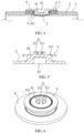
FIG. 1 is a schematic sectional diagram of a battery terminal and a first current collector before riveting in an internal connection structure of the battery terminal provided in a first embodiment of the present disclosure. -
FIG. 2 is a schematic sectional diagram of the battery terminal and the first current collector before riveting in the internal connection structure of the battery terminal provided in the first embodiment of the present disclosure. -
FIG. 3 is a schematic structural diagram of the battery terminal and the first current collector before riveting in the internal connection structure of the battery terminal provided in the first embodiment of the present disclosure. -
FIG. 4 is a schematic sectional diagram of the battery terminal and the first current collector after riveting in the internal connection structure of the battery terminal provided in the first embodiment of the present disclosure. -
FIG. 5 is a schematic sectional diagram of the battery terminal and the first current collector after riveting in the internal connection structure of the battery terminal provided in the first embodiment of the present disclosure. -
FIG. 6 is a schematic structural diagram of the battery terminal and the first current collector after riveting in the internal connection structure of the battery terminal provided in the first embodiment of the present disclosure. -
FIG. 7 is a schematic sectional diagram of the battery terminal and a battery case of the battery before riveting provided in a second embodiment of the present disclosure. -
FIG. 8 is a schematic sectional diagram of the battery terminal and a battery case of the battery after riveting provided in the second embodiment of the present disclosure. -
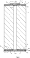
FIG. 9 is a schematic sectional diagram of the battery in a third embodiment of the present disclosure. -
FIG. 10 is a schematic partially enlarged diagram of A inFIG. 9 . -
FIG. 11 is a schematic partially enlarged diagram of B inFIG. 9 . -
FIG. 12 is a schematic structural diagram of a snapping protrusion portion in the internal connection structure of the battery terminal provided in a fourth embodiment of the present disclosure. -
FIG. 13 is a schematic partially enlarged diagram of C inFIG. 12 . - 1, roll core; 11, first electrode tab; 12, second electrode tab; 2, first current collector; 21, positive insulating part; 3, snapping portion; 31, riveting protrusion portion; 311, independent riveting protrusions; 312, riveting notch; 32, snapping protrusion portion; 321, first snapping protrusion; 322, second snapping protrusion; 3221, guide surface; 3222, snapping surface; 323, elastic deformation groove; 4, battery terminal; 41, first pole post; 411, riveting turnover groove; 42, first connecting bump; 43, concave hole; 5, battery case; 51, cover plate; 511, explosion-proof valve body structure; 52, supporting portion; 53, crimping portion; 54, sealing ring; 55, second connecting groove; 56, buckling groove; 57, third connecting groove; 6, terminal insulating part; 61, first connecting groove; 62, second connecting bump; 63, buckling portion; 7, internal insulating part; 71, third connecting bump; 8, second current collector; 9, riveting flange.
- In the present disclosure, unless otherwise specified and defined, terms "connect", "contact" and "fix" should be understood in a broad sense, for example, it may be a fixed connection, a detachable connection, or made as a whole; it may be a mechanical connection or an electrical connection; it may be a directly connection or an indirectly connection through an intermediate media; and it may be an internal connection of two components or an interaction relationship between two components. For those skilled in the art, meanings of the above terms in the present disclosure can be understood according to situations.
- In the present disclosure, unless otherwise specified and defined, a first feature is disposed "on" or "under" a second feature may include a direct contact between the first feature and the second feature, or a contact between the first feature and the second feature through other features rather than the direct contact. Moreover, that the first feature is disposed "above" or "up" the second feature includes that the first feature is directly above or obliquely above the second feature, or only indicate that a horizontal height of the first feature is greater than a horizontal height of the second feature. That the first feature is disposed "below", "under", or "underneath" of the second feature include that the first feature is directly below or obliquely below the second feature, or only indicate that the horizontal height of the first feature is less than the horizontal height of the second feature.
- In the description of this embodiment, terms indicating orientation or location relationships such as "up", "down", "left", and "right" are based on orientation or location relationships shown in drawings, which are only for a convenience of description and simplified operation, rather than indicating or implying that devices or elements referred to must have a specific orientation, be constructed and operated in a specific orientation, so it cannot be understood as a limitation of the present disclosure. In addition, terms "first" and "second" are only used to distinguish in terms of description and have no special meanings.
- The technical solution of the present disclosure will be further described in combination with
FIGs. 1 to 13 and through specific embodiments. - As shown in
FIG. 1 andFIG. 9 , an internal connection structure of a battery terminal is provided in the embodiment, including aroll core 1, a firstcurrent collector 2, and a snappingportion 3. Theroll core 1 is provided with afirst electrode tab 11 and asecond electrode tab 12. The firstcurrent collector 2 is connected to thefirst electrode tab 11, and the firstcurrent collector 2 is provided with a hole. The snappingportion 3 is disposed on an inner side of thebattery terminal 4. The snappingportion 3 passes through the hole and is riveted with the hole. Thebattery terminal 4 passes through the hole and is snapped and assembled with the firstcurrent collector 2 via the snappingportion 3. Thebattery terminal 4 is configured to enable a positive end of theroll core 1 extend outwards. The open pole in a middle of the firstcurrent collector 2 is assembled with the snappingportion 3 inside thebattery terminal 4, and the firstcurrent collector 2 and thebattery terminal 4 are snapped and connected by clamping to realize electrical connection. In this embodiment, the inner side refers to a side facing theroll core 1, and an outer side refers to a side away from theroll core 1. - In an embodiment, as shown in
FIG. 1, FIG. 2, and FIG. 3 , thebattery terminal 4 includes afirst pole post 41 located on the inner side. The snappingportion 3 includes ariveting protrusion portion 31. Theriveting protrusion portion 31 is disposed on an end surface of thefirst pole post 41. Theriveting protrusion portion 31 may be a hollow cylinder, or may be provided with ariveting notch 312. Theriveting notch 312 divides theriveting protrusion portion 31 into a plurality of independentriveting protrusions 311. - As shown in
FIG. 4, FIG. 5, and FIG. 6 , in this embodiment, theriveting protrusion portion 31 is provided with fourriveting notches 312, and theriveting protrusion portion 31 is divided into four independentriveting protrusions 311 arranged at even intervals. The middle of the firstcurrent collector 2 is provided with the open pole. Theriveting protrusion portion 31 passes through the open pole and is riveted with the open pole. Thebattery terminal 4 passes through the open pole and is riveted and assembled with the firstcurrent collector 2 by theriveting protrusion portion 31. The singleriveting protrusion portion 311 is folded outwards under an action of an external force to form riveting. And thebattery terminal 4 is configured to enable the positive end of theroll core 1 extend outwards - Implementation principle of the internal connection structure of the battery terminal in this embodiment is introduced below: the hole in the middle of the first
current collector 2 is assembled with the snappingportion 31 on the inner side of thebattery terminal 4. The firstcurrent collector 2 is connected to thebattery terminal 4 by riveting and snapping to achieve electrical connection. This does not need to use laser welding or resistance welding to achieve electrical connection inside the battery terminal, so as to avoid internal short circuit or excessive self-discharge of the battery caused by spatter and metals welded inside the battery. The connection is convenient and reliable, and use safety of the battery is improved. - As shown in
FIG. 7 and FIG. 8 , a battery is provided in the present embodiment, including the internal connection structure of the battery terminal as defined above. Thebattery terminal 4 connects with the inner side of the battery by the internal connection structure of the battery terminal. The internal connection structure of the battery terminal enables the firstcurrent collector 2 to be connected to thebattery terminal 4 by snapping to realize electrical connection, which is convenient and reliable, and improves the safety of the battery. - The battery also includes a
battery case 5, thebattery terminal 4, and a secondcurrent collector 8. A terminal insulatingpart 6 and an internalinsulating part 7 are disposed between thebattery terminal 4 and thebattery case 5. The terminal insulatingpart 6 is located outside thebattery case 5. The internalinsulating part 7 is located inside thebattery case 5. Thebattery terminal 4 is configured to enable the positive end of theroll core 1 extend outwards. The secondcurrent collector 8 is connected to thesecond electrode tab 12 and an inner side of thebattery case 5 respectively. Thebattery case 5 is configured to enable a negative end of theroll core 1 extend outwards. An external of thebattery terminal 4 is a positive output pole, and another part of thebattery case 5 except thebattery terminal 4 and the terminal insulatingpart 6 is a negative output pole. Therefore, a same-side output tab structure of the positive and negative poles of the battery is realized. - As shown in
FIG. 7 and FIG. 8 , thefirst pole post 41 passes through a through hole defined on an end of thebattery case 5. The terminal insulatingpart 6 inserts into the through hole to strengthen an insulation effect between thebattery terminal 4 and thebattery case 5. The internalinsulating part 7 inserts into the through hole and is disposed between the terminal insulatingpart 6 and an inner wall of the through hole to strengthen the insulation effect between thebattery terminal 4 and thebattery case 5. The terminal insulatingpart 6 and the internal insulatingpart 7 form double protective insulation for thebattery terminal 4 at the through hole of thebattery case 5. An inner side of thefirst pole post 41 is disposed with ariveting flange 9. An inner wall of theriveting flange 9 near a center of thefirst pole post 41 is inclined, so that the inner wall of theriveting flange 9 is open. Thefirst pole post 41 is provided with ariveting turnover groove 411 adjacent to theriveting flange 9. Theriveting turnover groove 411 is located on a side of theriveting flange 9 close to the center of thefirst pole post 41, and theriveting turnover groove 411 makes theriveting flange 9 easier to bend outwards to form a riveting structure after being stressed. Thebattery terminal 4 passes through the through hole of thebattery case 5 via theriveting flange 9 and is riveted and assembled with thebattery case 5. Theriveting flange 9 is pressed on a surface of the internal insulatingpart 7 after riveted and folded, so as to realize a connection between thebattery terminal 4 and thebattery case 5. The fixed and formed battery shell assembly is used as a battery container, and the connection is convenient and reliable. - In an embodiment, structural dimensions of the
battery case 5 are defined as follows: a diameter code of the through hole of thebattery case 5 is φ-11, a diameter code of thefirst pole post 41 is φ-12, and a diameter code of an outer insulating part below a positive pole post is φ-13. A value of φ-11 ranges from 3mm to 20mm, φ -12=( φ-11)+W0, φ-13=( φ-12)+W2. The value of Φ -11 ranges from 3mm to 20mm, φ-12=( φ-11)+W0, φ-13=( φ-12)+W2, wherein a value of W0 ranges fromlmm to15mm, and a value of W1 ranges from 0.8mm to 10mm. - In an embodiment, a diameter φ-01 of the
riveting protrusion portion 31 of thebattery terminal 4 ranges from 3mm to 8 mm. A wall thickness of theriveting protrusion portion 31 ranges from 0.1mm to 1 mm. A wall thickness of a flanging turned outwards after the riveting protrudingportion 31 is riveted is t-02. The wall thickness t-02 of the flanging will be extension and thinning, a thickness range of t-02 is 0.80≤t-01/t-02<1. W01 is a flanging width of the riveting protrudingportion 31, which requires 2-3 times of t-01, a diameter φ-02 of the riveting protrudingportion 31 after flanging is φ-01+2×W01. - Design requirements for structural dimensions of the
riveting protrusion portion 31 of thebattery terminal 4, the diameter code of the through hole of thebattery case 5 is φ-11, a diameter code of thefirst pole post 41 passing through the through hole of thebattery terminal 4 is φ2-3, wherein a range of φ2-3 is ( φ -11)-W3, and a value of W3 ranges from 0.3mm to 3mm. Circular and annularriveting turnover groove 411 is disposed on the inner side ofbattery terminal 4, and an inner diameter code of theriveting turnover groove 411 is φ2-1. An outer code of theriveting turnover groove 411 is φ2-2, wherein a range of φ2-2 is ( φ2-3)-W4, a value of W4 ranges from 0.3mm to 3mm. The range of φ2-1 is ( φ 2-2)-W5, a value of W5 ranges from 0.3mm to 3mm, and ( φ2-1)>5mm. A diameter code of theriveting flange 9 inside thebattery terminal 4 after riveting is φ2-4. The range of φ 2-4 is ( φ-11)+G1, and a value of G1 ranges from 0.8mm to 5mm. A diameter code of the internal insulatingpart 7 is φ2-5, a range of φ2-5 is ( φ-11+G1)+G2, and a value of G2 ranges from 0.5mm to 25mm, and the value of G2 does not exceed φ 1-t-01. Aconcave hole 43 is defined outside thebattery terminal 4. A diameter code of theconcave hole 43 is φ2-0, wherein a value of the φ2-0 ranges from 0.5mm to 15mm. - Implementation principle of the internal connection structure of the battery in this embodiment is introduced below: the first
current collector 2 is connected to thebattery terminal 4 by riveting and snapping to achieve electrical connection in the internal connection structure of the battery terminal. This does not need to use laser welding or resistance welding to achieve electrical connection inside thebattery terminal 4, so as to avoid internal short circuit or excessive self-discharge of the battery caused by spatter and metals welded inside the battery. The connection is convenient and reliable, and the use safety of the battery is improved. The external of thebattery terminal 4 is the positive output pole, and another part of thebattery case 5 except thebattery terminal 4 and the terminal insulatingpart 6 is the negative output pole. Therefore, the same-side output tab structure of the positive and negative poles of the battery is realized. - A battery is provided in this embodiment. A difference from the second embodiment is that, as shown in
FIG. 9 andFIG. 10 , in order to increase stability of a connection between thebattery terminal 4 and the terminal insulatingpart 6, a first connectingbump 42 is disposed on thebattery terminal 4, and a first connectinggroove 61 for thefirst connection bump 42 to insert into is provided at a corresponding position of the terminal insulatingpart 6. In order to increase stability of a connection between the terminal insulatingpart 6 and thebattery case 5, a second connectingbump 62 is disposed on the terminal insulatingpart 6, and a second connectinggroove 55 for thesecond connection bump 62 to insert into is provided at a corresponding position of thebattery case 5. In order to increase an insulating effect of the terminal insulatingpart 6, the terminal insulatingpart 6 inserts into the through hole of thebattery case 5, and a bucklingportion 63 extending in a direction away from a center of thebattery terminal 4 is provided. A bucklinggroove 56 for the bucklingpart 63 to insert into is disposed at a corresponding position on the inner wall of thebattery case 5. - In an embodiment, the inner wall of the
battery case 5 is provided with a third connectinggroove 57, and the internal insulatingpart 7 is provided with a third connectingbump 71 inserting into the third connectinggroove 57. This makes a connection between the internal insulatingpart 7 and thebattery case 5 more stable. After theriveting flange 9 folds outwards, a side wall of theriveting flange 9 abuts against the inner wall of the internal insulatingpart 7. And a side of theriveting flange 9 away from the center of the battery abuts against the bucklingportion 63 of the terminal insulatingpart 6. - A positive insulating
part 21 is disposed between the internal insulatingpart 7 and theroll core 1. A side of the positive insulatingpart 21 away from the center of the battery abuts against theriveting flange 9 and extends between the firstcurrent collector 2 and thefirst pole post 41. - As shown in
FIG. 9 andFIG. 11 , an end of thebattery case 5 away from thebattery terminal 4 is provided with an opening, and acover plate 51 is disposed at a position of the opening. A sealingring 54 is disposed at a gap between thecover plate 51 and the opening. An internal wall of the opening extends toward outside of thebattery case 5 with a supportingportion 52. The supportingportion 52 is configured to support thecover plate 51. The supportingportion 52 is connected to a crimpingportion 53, and the crimpingportion 53 is configured to press thecover plate 51 on the supportingportion 52. The sealingring 54 is also located between the crimpingportion 53 and the supportingportion 52. The sealingring 54 strengthens sealing between thecover plate 51 and thebattery case 5. Thecover plate 51 is provided with an explosion-proofvalve body structure 511, and the explosion-proofvalve body structure 511 is coaxial with the battery. - In an embodiment, the supporting
portion 52 is realized by rolling a position 8-14mm from a lower edge of the opening of thebattery case 5, and then the sealingring 54 and thecover plate 51 are placed on the supportingportion 52. The crimpingportion 53 is formed by crimping a position 3-6 mm from the lower edge of the opening of thebattery case 5, so that the crimpingportion 53 and the supportingportion 52 compress the sealingring 54 and thecover plate 51 to form a seal and complete battery packaging. Thecover plate 51 and thebattery case 5 are insulated by the sealingring 54 . Thecover plate 51 is in contact with the protrusion portion of the secondcurrent collector 8, therefore, thecover plate 51 is negatively charged. - Implementation principle of the battery in this embodiment is introduced below: this battery provides a type of sealing structure in which the positive pole is integrated in the
battery case 5. Through a cooperative use of the crimpingportion 53 and the supportingportion 52, thecover plate 51 and the sealingring 54 are assembled on thebattery case 5 to form the seal and complete the battery packaging. The packaging is convenient, the connection is reliable, and the use safety and production efficiency of the battery are improved. - This embodiment provides a battery, as shown in
FIG. 12 and FIG. 13 , a difference from the first embodiment is that, the snappingportion 3 includes a snappingprotrusion portion 32. The snappingprotrusion portion 32 is disposed on an end face of thefirst pole post 41. In an embodiment, the snappingprotrusion portion 32 includes afirst snapping protrusion 321 and asecond snapping protrusion 322. A first end of thefirst snapping protrusion 321 is fixedly connected to the inner side of thebattery terminal 4. A second end of thefirst snapping protrusion 321 is fixedly connected to thesecond snapping protrusion 322. An end face of thesecond snapping protrusion 322 away from thebattery terminal 4 is an aligninginclined surface 3221. An end face of thesecond snapping protrusion 322 close to the battery terminal is asnapping surface 3222. The snappingsurface 3222 abuts against the firstcurrent collector 2. An end face of the snappingprotrusion portion 32 away from thebattery terminal 4 is provided with anelastic deformation groove 323. - In this embodiment, the snapping
protrusion portion 32 is snapped through the open pole, thesecond snapping protrusion 322 is close to a center of theelastic deformation groove 323 of the snappingprotrusion portion 32 under an action of an external force. The guide surface has a guiding role until thebattery terminal 4 passes through the through hole by the snappingprotrusion 32 and is snapped and assembled with the firstcurrent collector 2. The snappingsurface 3222 abuts against the end face of the firstcurrent collector 2. A distance between the snappingsurface 3222 and an internal measuring end face of thebattery terminal 4 is approximately the same as a thickness of the firstcurrent collector 2, which can better clamp the firstcurrent collector 2 between the inner end face of thebattery terminal 4 and thesnapping surface 3222, so as to play a role of stable electrical connection. Thebattery terminal 4 can realize outwards stable output of the positive end of theroll core 1. - Implementation principle of the internal connection structure of the battery terminal in this embodiment is introduced below: the hole in the middle of the first
current collector 2 of theroll core 1 is assembled with the snappingportion 32 on the inner side of thebattery terminal 4. The firstcurrent collector 2 is connected to thebattery terminal 4 by clamping to achieve electrical connection. This does not need to use laser welding or resistance welding to achieve electrical connection inside thebattery terminal 4, so as to avoid internal short circuit or excessive self-discharge of the battery caused by spatter and metals welded inside the battery. The connection is convenient and reliable, and the use safety of the battery is improved.
Claims (15)
- An internal connection structure of a battery terminal, comprising:a roll core (1), wherein the roll core (1) is provided with a first electrode tab (11) and a second electrode tab (12);a first current collector (2), wherein the first current collector (2) is connected to the first electrode tab (11), and the first current collector (2) is provided with a hole; anda snapping portion (3), wherein the snapping portion (3) is disposed on an inner side of the battery terminal (4), the snapping portion (3) passes through the hole and is snapped with the hole, the battery terminal (4) passes through the hole and is snapped and assembled with the first current collector (2) via the snapping portion (3), and the battery terminal (4) is configured to enable a positive end of the roll core (1) extend outwards.
- The internal connection structure of the battery terminal according to claim 1, wherein the snapping portion (3) comprises a riveting protrusion portion (31).
- The internal connection structure of the battery terminal according to claim 2, wherein the riveting protrusion portion (31) is disposed with a riveting notch (312), and the riveting notch (312) is configured to separate the riveting protrusion portion (31) into a plurality of independent riveting protrusions (311).
- The internal connection structure of the battery terminal according to claim 1, wherein the snapping portion (3) comprises a snapping protrusion portion (32).
- The internal connection structure of the battery terminal according to claim 4, wherein the snapping protrusion portion comprises a first snapping protrusion (321) and a second snapping protrusion (322), a first end of the first snapping protrusion (321) is fixedly connected to the inner side of the battery terminal (4), and a second end of the first snapping protrusion (321) is fixedly connected to the second snapping protrusion (322), an end face of the second snapping protrusion (322) away from the battery terminal (4) is an aligning inclined surface (3221), an end face of the second snapping protrusion (322) close to the battery terminal (4) is a snapping surface (3222), and the snapping surface (3222) abuts against the first current collector (2).
- The internal connection structure of the battery terminal according to claim 5, wherein a distance between the snapping surface (3222) and an inner end face of the battery terminal (4) is approximately the same as a thickness of the first current collector (2).
- The internal connection structure of the battery terminal according to any one of claims 4-6, wherein an end face of the snapping protrusion portion (32) away from the battery terminal (4) is provided with an elastic deformation groove (323).
- A battery, comprising the internal connection structure of the battery terminal as described in any one of claims 1-7.
- The battery according to claim 8, further comprising:a battery case (5);the battery terminal (4);a terminal insulating part (6) and an internal insulating part (7) disposed between the battery terminal (4) and the battery case (5), wherein the terminal insulating part (6) is located outside the battery case (5), the internal insulating part (7) is located inside the battery case (5), the battery terminal (4) is connected to the internal connection structure of the battery terminal, and the battery terminal (4) is configured to enable the positive end of the roll core (1) extend outwards; anda second current collector (8), wherein the second current collector (8) is connected to a second electrode tab (12) and an inner part of the battery case (5) respectively, and the battery case (5) is configured to enable a negative end of the roll core (1) extend outwards.
- The battery according to claim 9, wherein the battery terminal (4) comprises a first pole post (41) configured to pass through a through hole disposed at an end of the battery case (5);
an inner side of the first pole post (41) is provided with a riveting flange (9), and the battery terminal (4) is configured to pass through the through hole and to be riveted and assembled with the battery case (5) via the riveting flange (9) to fix the first terminal (4) with the battery case (5). - The battery according to claim 10, wherein the first pole post (41) is provided with a riveting turnover groove (411) adjacent to the riveting flange (9), and the riveting turnover groove (411) is located at a side of the riveting flange (9) close to a center of the first pole post (41).
- The battery according to any one of claims 9-10, further comprising a cover plate (51), wherein an end of the battery case (5) away from the battery terminal (4) is provided with an opening, and the cover plate (51) is disposed at a position of the opening.
- The battery according to claim 12, wherein an internal wall of the opening extends toward outside of the battery case (5) to form a supporting portion (52), the supporting portion (52) is configured to support the cover plate (51), the supporting portion (52) is connected to a crimping portion (53), and the crimping portion (53) is configured to press the cover plate (51) on the supporting portion (52).
- The battery according to claim 12, further comprising a sealing ring (54) disposed at a gap between the cover plate (51) and the opening.
- The battery according to claim 12, wherein the cover plate (51) is provided with an explosion-proof valve body structure (511), and the explosion-proof valve body structure (511) is coaxial with the battery.
Applications Claiming Priority (2)
| Application Number | Priority Date | Filing Date | Title |
|---|---|---|---|
| CN202221432896.7U CN218039734U (en) | 2022-06-09 | 2022-06-09 | First terminal internal connection structure and battery |
| PCT/CN2022/126314 WO2023236410A1 (en) | 2022-06-09 | 2022-10-20 | Internal battery terminal connection structure and battery |
Publications (2)
| Publication Number | Publication Date |
|---|---|
| EP4311017A1 true EP4311017A1 (en) | 2024-01-24 |
| EP4311017A4 EP4311017A4 (en) | 2025-02-26 |
Family
ID=84376339
Family Applications (1)
| Application Number | Title | Priority Date | Filing Date |
|---|---|---|---|
| EP22822833.4A Pending EP4311017A4 (en) | 2022-06-09 | 2022-10-20 | INTERNAL BATTERY TERMINAL CONNECTION STRUCTURE AND BATTERY |
Country Status (5)
| Country | Link |
|---|---|
| US (1) | US20240304960A1 (en) |
| EP (1) | EP4311017A4 (en) |
| CN (1) | CN218039734U (en) |
| DE (1) | DE212022000396U1 (en) |
| WO (1) | WO2023236410A1 (en) |
Families Citing this family (5)
| Publication number | Priority date | Publication date | Assignee | Title |
|---|---|---|---|---|
| KR102570308B1 (en) * | 2022-10-27 | 2023-08-24 | 삼성에스디아이 주식회사 | Cylindrical secondary battery |
| CN116174643B (en) * | 2023-03-03 | 2026-03-10 | 蜂巢能源科技股份有限公司 | Connection method and connection structure of battery cell tab and cover plate |
| KR102853427B1 (en) * | 2023-06-09 | 2025-09-02 | 삼성에스디아이 주식회사 | Secondary battery |
| CN120693742A (en) * | 2023-09-28 | 2025-09-23 | 宁德时代新能源科技股份有限公司 | Battery cells, batteries and electrical devices |
| KR20260061843A (en) * | 2024-10-28 | 2026-05-06 | 에스케이온 주식회사 | Secondary battery |
Family Cites Families (11)
| Publication number | Priority date | Publication date | Assignee | Title |
|---|---|---|---|---|
| JP2000138056A (en) * | 1998-11-02 | 2000-05-16 | Japan Storage Battery Co Ltd | Non-aqueous electrolyte battery |
| JP2010033940A (en) * | 2008-07-30 | 2010-02-12 | Toshiba Corp | Battery |
| DE112012000620T5 (en) * | 2011-01-31 | 2013-11-07 | Gs Yuasa International Ltd. | Electric storage element and method for its production |
| JP2015097174A (en) * | 2013-11-15 | 2015-05-21 | 日立オートモティブシステムズ株式会社 | Secondary battery |
| KR102439848B1 (en) * | 2015-04-17 | 2022-09-01 | 삼성에스디아이 주식회사 | secondary battery |
| JP2019121515A (en) * | 2018-01-05 | 2019-07-22 | 第一精工株式会社 | Snap button type electric connector |
| CN211350696U (en) * | 2019-12-31 | 2020-08-25 | 成都市银隆新能源有限公司 | Cylindrical lithium ion battery structure |
| CN212136493U (en) * | 2020-06-16 | 2020-12-11 | 合肥国轩高科动力能源有限公司 | Positive negative pole apron structure of cylinder battery |
| CN113346201A (en) * | 2021-05-21 | 2021-09-03 | 湖北亿纬动力有限公司 | Cylindrical battery, battery module and battery pack |
| CN215578674U (en) * | 2021-05-21 | 2022-01-18 | 湖北亿纬动力有限公司 | Assembling structure of positive pole and positive current collecting plate and battery |
| CN215070164U (en) * | 2021-06-30 | 2021-12-07 | 比亚迪股份有限公司 | A block subassembly and cylinder battery for cylinder battery |
-
2022
- 2022-06-09 CN CN202221432896.7U patent/CN218039734U/en active Active
- 2022-10-20 US US18/003,467 patent/US20240304960A1/en active Pending
- 2022-10-20 EP EP22822833.4A patent/EP4311017A4/en active Pending
- 2022-10-20 DE DE212022000396.9U patent/DE212022000396U1/en active Active
- 2022-10-20 WO PCT/CN2022/126314 patent/WO2023236410A1/en not_active Ceased
Also Published As
| Publication number | Publication date |
|---|---|
| EP4311017A4 (en) | 2025-02-26 |
| WO2023236410A1 (en) | 2023-12-14 |
| CN218039734U (en) | 2022-12-13 |
| DE212022000396U1 (en) | 2025-01-17 |
| US20240304960A1 (en) | 2024-09-12 |
Similar Documents
| Publication | Publication Date | Title |
|---|---|---|
| US20240304960A1 (en) | Internal connection structure of battery terminal and battery | |
| CN110176557B (en) | Secondary battery and top cover assembly thereof | |
| KR100922352B1 (en) | Secondary battery | |
| EP2677563B1 (en) | Rechargeable battery and module of the same | |
| KR101233342B1 (en) | Rechargeable battery pack and connection tab using the same | |
| KR101097220B1 (en) | Secondary battery | |
| EP4290659A1 (en) | Battery and assembly process therefor | |
| EP2892086A1 (en) | Rectangular secondary battery | |
| CN217934117U (en) | Battery pack | |
| CN108767143A (en) | Secondary cell's top cap subassembly and secondary cell | |
| CN218827723U (en) | Current collector sealing cap's battery cell | |
| CN217158534U (en) | Explosion-proof valve, battery cover plate and battery | |
| JP5203729B2 (en) | Secondary battery and battery module | |
| CN216213745U (en) | Square secondary battery's top cap and secondary battery | |
| CN223378403U (en) | Battery cell | |
| EP4250440B1 (en) | Cylindrical battery | |
| CN220042225U (en) | Composite pole, top cover structure and secondary battery | |
| EP4425655A2 (en) | Cover assembly, battery and battery pack | |
| KR20240156058A (en) | Cylindrical Secondary Battery | |
| CN116598670A (en) | Cylindrical battery | |
| CN120432763A (en) | Battery cover assembly and battery | |
| CN114639863A (en) | Cylindrical battery and method for manufacturing the same | |
| JP2000100398A (en) | Cap assembly for secondary battery and method of manufacturing the same | |
| CN219393544U (en) | Cylindrical battery | |
| KR100637440B1 (en) | Secondary Battery and Terminal Assembly Used Here |
Legal Events
| Date | Code | Title | Description |
|---|---|---|---|
| STAA | Information on the status of an ep patent application or granted ep patent |
Free format text: STATUS: UNKNOWN |
|
| STAA | Information on the status of an ep patent application or granted ep patent |
Free format text: STATUS: THE INTERNATIONAL PUBLICATION HAS BEEN MADE |
|
| PUAI | Public reference made under article 153(3) epc to a published international application that has entered the european phase |
Free format text: ORIGINAL CODE: 0009012 |
|
| STAA | Information on the status of an ep patent application or granted ep patent |
Free format text: STATUS: REQUEST FOR EXAMINATION WAS MADE |
|
| 17P | Request for examination filed |
Effective date: 20221221 |
|
| AK | Designated contracting states |
Kind code of ref document: A1 Designated state(s): AL AT BE BG CH CY CZ DE DK EE ES FI FR GB GR HR HU IE IS IT LI LT LU LV MC ME MK MT NL NO PL PT RO RS SE SI SK SM TR |
|
| A4 | Supplementary search report drawn up and despatched |
Effective date: 20250129 |
|
| RIC1 | Information provided on ipc code assigned before grant |
Ipc: H01M 50/107 20210101ALI20250123BHEP Ipc: H01M 50/531 20210101ALI20250123BHEP Ipc: H01M 50/567 20210101ALI20250123BHEP Ipc: H01M 50/559 20210101AFI20250123BHEP |
|
| DAV | Request for validation of the european patent (deleted) | ||
| DAX | Request for extension of the european patent (deleted) |